Abstract
An analysis of the influence of applied loads on free vibrations of plate and shell panels made of functionally graded materials is analyzed in the present work. Formulations for the static analysis considering geometrically nonlinear behavior, as well as linear buckling and free vibrations analyses are considered. A calculation of the through-thickness stress distribution is also performed. The finite element model is based on a higher order shear deformation theory using a non-conforming flat triangular plate/shell element with three nodes, and eight degrees of freedom per node is used in the numerical implementation. The results obtained with this numerical model are presented, discussed, and compared with alternative solutions published by other authors in some benchmark applications.
1. Introduction
Plate/shell panels have applications in a wide range of engineering situations, such as aeronautics and aerospace structural systems, among many others. Structures made of composite materials have been widely used to satisfy high performance demands. In such structures, stress singularities may occur at the interface between two different materials. In functionally graded structures, the smooth and continuous variation of the properties from one surface to the other eliminates abrupt changes in the stress and displacement distributions. In addition, a ceramic phase with low thermal conductivity can resist a high thermal environment, while the metal phase is strong with a mechanical load.
Thousands of studies of plate/shell panels composite structures have been published in the last five decades. More recently, a great number of works have also been published in functionally graded material (FGM) structures. Here, some representative works involving plate/shell panels and continuous variation of the material properties through the thickness direction, used to validate the static nonlinear and linear buckling and free vibrations analyses, are mentioned [1,2,3,4,5,6,7,8,9,10,11,12,13]. The aim and the novelty of this paper is to study the influence of external applied loads, which give the panels a state of stress and a slightly different geometry in comparison with the initial panel on the free vibration analysis of the FGM plates–shells, considering the geometrically nonlinear behavior.
Woo and Meguid [1] addressed the large deflections of FGM plates/shells, Reddy and Arciniega [2,3] studied the free vibrations and geometrically nonlinear analysis of FGM shells, Kim et al. [4] presented a formulation for small strains and large displacements, and Zhao and Liew [5] performed a geometrically nonlinear analysis of FGM shells. Tran et al. [6] presented the stability equations of FGM plates, while Thai and Kim [7] and Natarajan et al. [8] addressed the response of FGM plates in bending and free vibrations. Yin et al. [9], Moita et al. [10,11], and Long et al. [12] presented models for a geometrically nonlinear analysis of FGM plates and shells. Phan et al. [13] studied the buckling of FGM plates and shells.
In this paper, the influence of the applied loads on the natural frequencies of functionally graded material plate/shell panels subjected to general loadings is analyzed. The formulation considers the following: geometrically nonlinear deformation with the through-thickness stress distribution calculations, linear buckling, and free vibration analyses. A finite element model based on a higher order shear deformation theory using a non-conforming flat triangular plate/shell element with three nodes with eight degrees of freedom per node was adopted to study the plate/shell structures. This finite element model was revealed to be very efficient in the analysis of the proposed structures—it is easy to model the geometry, there is a low number of total degrees of freedom, there is good accuracy of the results, and the model is fast.
The solutions of some illustrative examples were performed, and the results are presented and discussed.
2. Formulation of the P-FGM Model
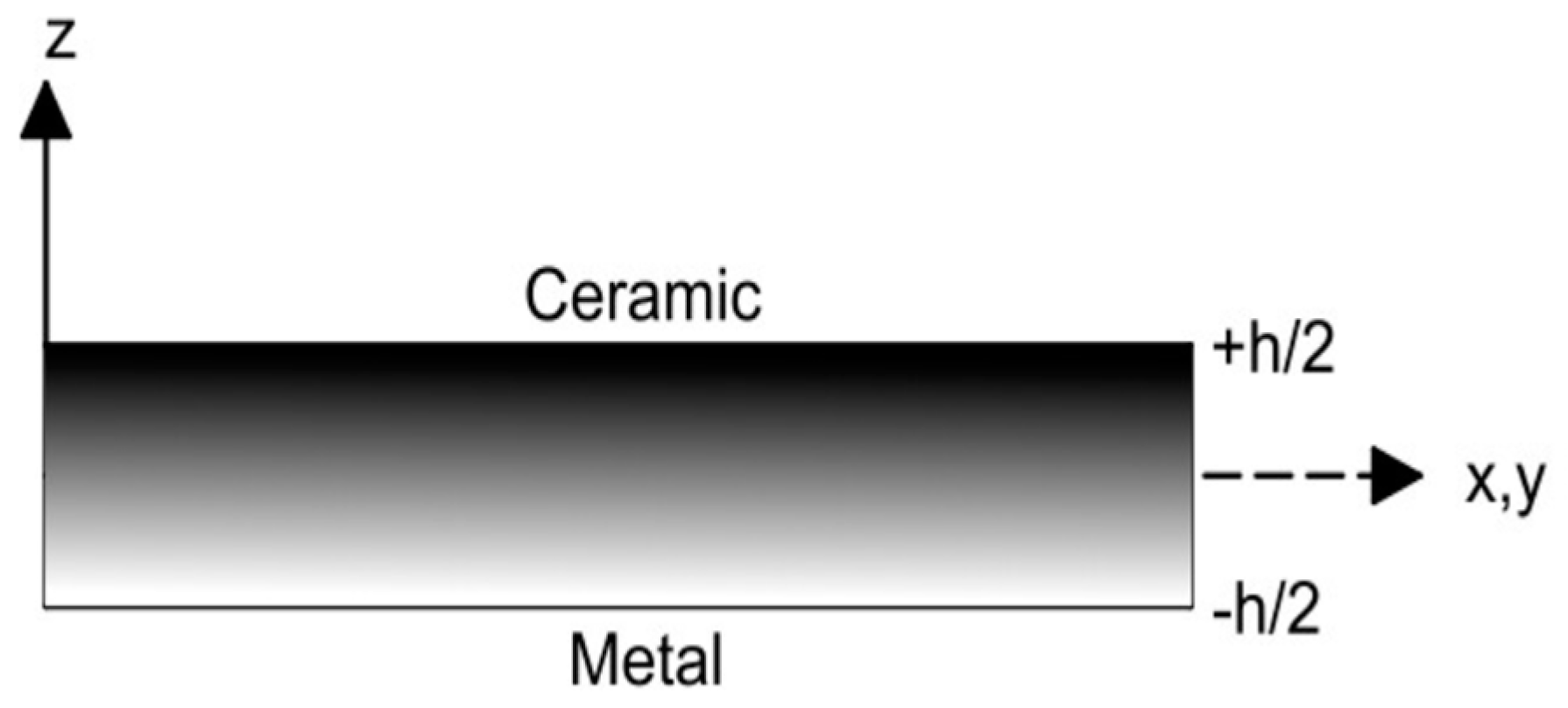
An FGM is made by mixing two distinct isotropic material phases, for example, a ceramic and a metal. In this work, the material properties of an FGM plate/shell structure are assumed to change continuously throughout the thickness (Figure 1), according to the volume fraction of the constituent materials, given by the power law function (Bao and Wang [14]). In addition, the continuous variation of the material mixture is approximated using a certain number of virtual layers, k, throughout the thickness direction-layer approach. The volume fraction of the ceramic and metal phases for each virtual layer is defined according to the power law:
where is the thickness coordinate of the mid-surface of each layer and p is the gradient index of the power law.

Figure 1.
Cross-section representation of an FGM plate.
Once the volume fractions of the ceramic and the metal, and , are defined, Young’s modulus E, the shear modulus , the Poisson ratio , or the mass density of each virtual layer k of the FGM plate/shell can be determined:
2.1. Displacement Fields and Strain-Displacement Relations
The displacement field of the plate/shell domain is based on Reddy’s third-order shear deformation theory [10,11]:
where are displacements of a generic point in the middle plane referred to the local axes—x, y, z directions; are the rotations of the normal to the middle plane about the axis (clockwise) and axis (anticlockwise); are the slopes of the tangents of the deformed mid-surface in the directions; , with denoting the total thickness of the plate/shell structure; and ґ is the time.
For the geometrically nonlinear behavior analysis, the strain tensor is conveniently represented in terms of the linear and nonlinear parts of the strain tensor as follows:
The linear strain components associated with the displacement fields defined above can be written in the following form:
Therefore, we can write in the detailed form:
where c2 = 4/h2.
2.2. Constitutive Relations for the FGM Structures
The stress–strain relations are defined based on the stress–strain relations in each layer k, which can be written as follows:
where is the stress vector, is the strain vector, and is the elasticity matrix of the k layer:
By integrating through the thickness, the linear elastic constitutive equation for each virtual layer, k, can be written as follows:
where is the resultant forces and moments, the constitutive matrix, and the sub-matrices of are given by the following:
3. Finite Element Approach
A non-conforming triangular plate/shell finite element model having three nodes and eight degrees of freedom per node is used. The degrees of freedom at each node are the displacements, the slopes, and the rotations,
The rotation is introduced to consider a fictitious stiffness coefficient to eliminate the problem of a singular stiffness matrix for general shape structures [15]. The finite element formulation is obtained by the superposition of a membrane element with a bending element, and the side 1–2 of the triangle is coincident with the axis x of the local system attached to the finite element, with the origin at node 1 (Figure 2).
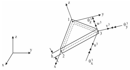
Figure 2.
Finite element geometry.
The element displacement vectors at any point of the mid-surface in the local coordinates (x,y) are obtained in terms of the corresponding nodal variables through linear shape functions , and the transverse displacement and slopes are expressed in terms of the corresponding nodal variables through cubic shape functions , [15], which are also given in terms of area coordinates [15].
The displacement field can be represented in matrix form as follows:
where the matrix of the shape functions and the appropriate matrix Z having powers of are as follows:
4. Virtual Work Principle
4.1. Static Analysis
The governing equations of the nonlinear problem are obtained from the virtual work principle in conjugation with an updated Lagrangian formulation [16,17]. A reference configuration is associated with time t, and the updated configuration is associated with the current time .
where is the element external virtual work.
The membrane, bending, and shear strains, as well the higher order bending and shear strains can be represented by the following:
where the, , , , and are components of the strain-displacement matrix and are given explicitly in Moita et al. [18].
The virtual work principle applied to a finite element can be written in the following matrix form:
From this equation, the element linear stiffness matrix the element geometric stiffness matrix , the element external load vector , and the element internal force vector can be obtained [18].
The element geometric stiffness matrix is given by the following:
To solve for general structures, these matrices and vectors, initially computed in the local coordinate system attached to the element, are transformed to a global coordinate system in the usual way [15]. Afterwards, by adding the contributions of all the elements in the domain, the system equilibrium equations can be obtained as follows:
Using the Newton–Raphson incremental-iterative method, the incremental equilibrium path is obtained, and in the case of snap-through occurrence, the automatic arc-length method is used [19,20] via Equation (21) written in the following form:
and an additional equation is employed to constrain the length of a load step:
where is a fixed (reference) load vector, is a load factor, is the incremental load factor within the load step, and is the arc length.
In Crisfield [20], it is stated that the current stiffness parameter is a very useful index to give some scalar measure of the degree of non-linearity. In its unscaled form, it effectively measures the ‘stiffness’ of the system. In the present work, when using the arc length for any case studied here, this method calculates a stiffness parameter (herein called CSTIF) at any load level, starting with the value of CSTIF = 1.0 for the panel unloaded (stress-free state). In the incremental-iterative process, when the CSTIF became less than 1.0, it means the stiffness was decreasing, and if the CSTIF was greater than 1.0, the stiffness was increasing.
4.2. Linear Buckling Analysis
For the linear mechanical buckling analysis, only one load increment was used, and Equation (21) becomes:
The linear elastic buckling standard eigenvalue problem is then given by the following:
4.3. Free Vibration Analysis
The Hamilton principle is used to formulate the governing equations for vibration analysis:
where the element mass matrix Me is given by the following:
After assembling all the elements, the natural frequencies and the respective mode shapes are obtained by solving the standard eigenvalue problem:
The free vibrations of the loaded panels are obtained considering the corresponding stiffness matrix by the following equation:
5. Applications
First, a few numerical applications are presented, which serve for model validation against alternative results published by other researchers in different analyses, and also allow us to calculate load-displacement paths, which will give the information about the normal and shear stresses, limit points, and inflection points. The later applications, which address the aim of this work, show the non-linear analysis by using Equations (22) and (23) to obtain the influence of the applied loading at several load levels on the free vibrations of the FGM plates and shells. The updated geometry and the tangential stiffness matrix at each load level is calculated, and the eigenvalue problem in Equation (30) is solved for that loading condition to obtain the natural frequencies.
5.1. Nonlinear Analysis of a Simply Supported and Clamped FGM Square Plate under Uniform Transverse Pressure
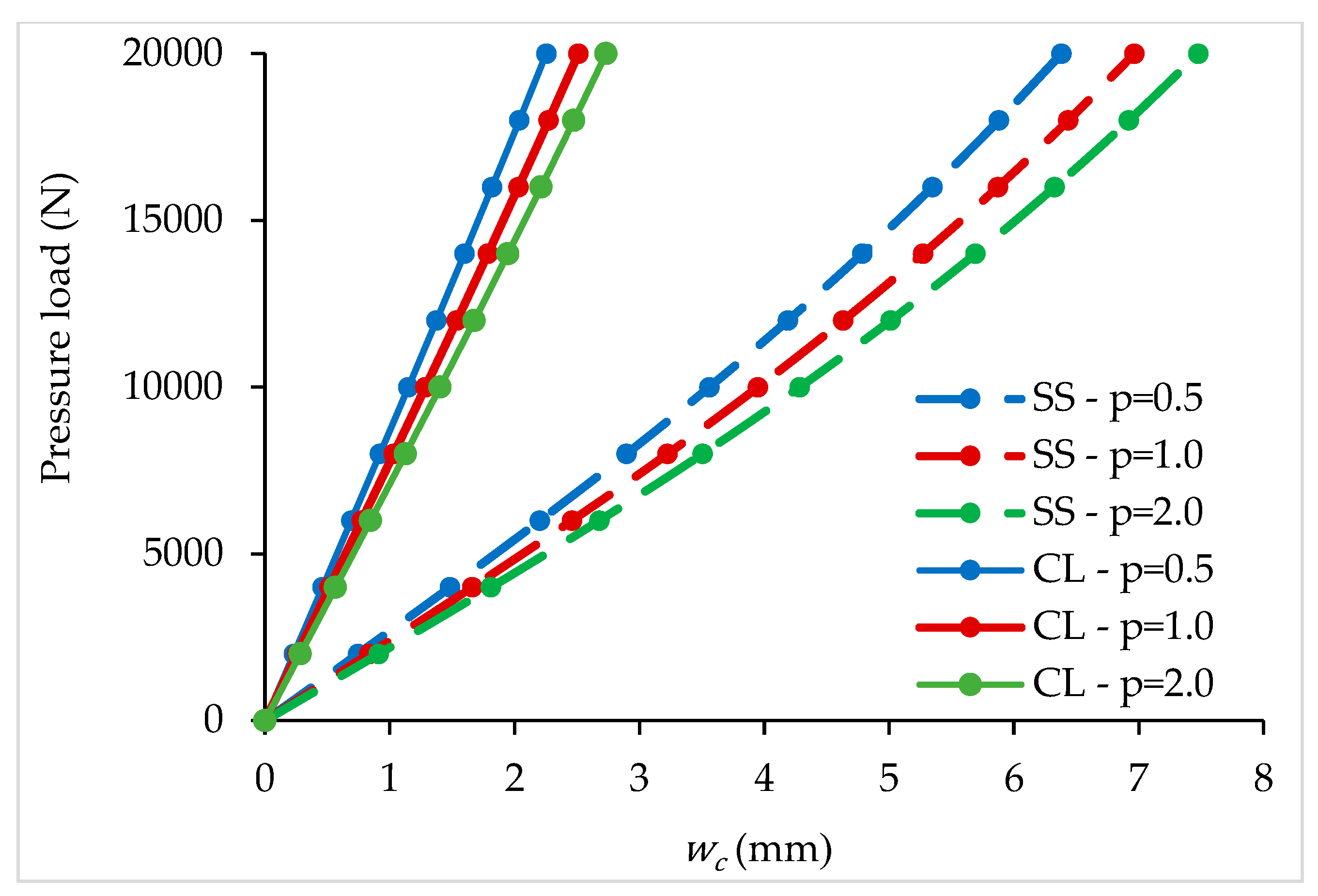
Simply supported (SS) and clamped (CL) FGM square plates subjected to a uniform pressure load are considered in this first numerical application. The geometry is defined by the side dimension a = 1.0 m and the thickness h = 0.01 m. Three gradient indexes are considered: p = 0.5, p = 1, and p = 2. The plate, discretized through the thickness using 20 virtual layers, is made of constituents zirconia and aluminum ( = 151 × 109 Pa, = 0.3, ρc = 5700 kg/m3, =70 × 109 Pa, = 0.3, ρm = 2702 kg/m3). An incremental-iterative loading is applied, and the load-displacement paths obtained for the center of the plate are presented in Figure 3. This analysis had been validated in Moita et al. [11], although for different geometry and material properties. It is observed that the displacements increase when the gradient index increases. This happens because > , and as p increases, the volume fraction of ceramic decreases.
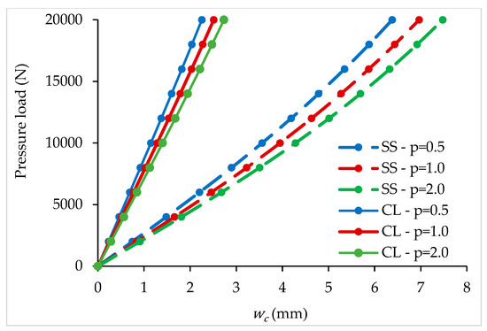
Figure 3.
Load-displacement paths for different gradient indexes.
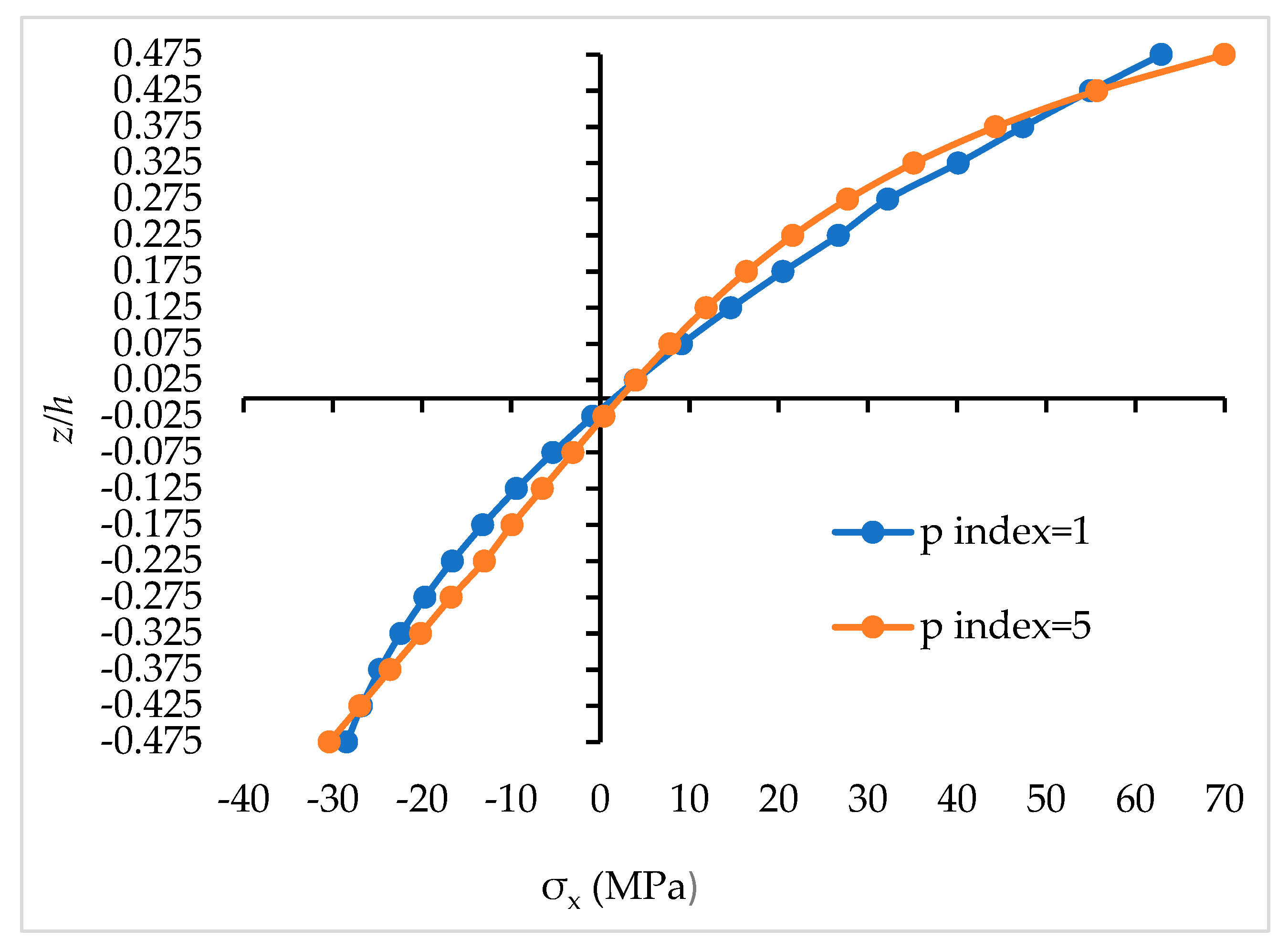
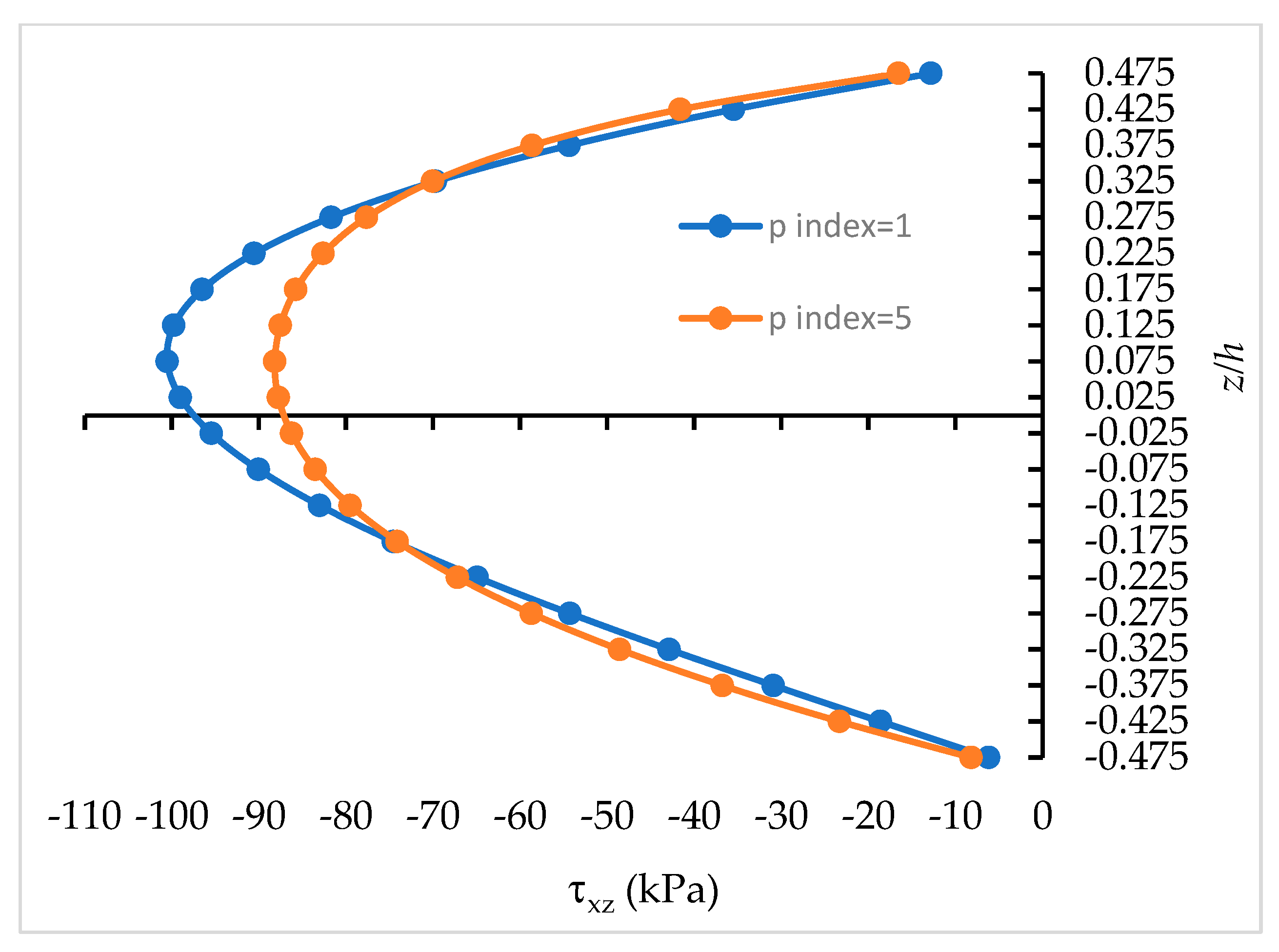
For the last load increment, considering the simply supported plate, the through-the-thickness distributions of the total normal and transverse shear stresses at the Gauss point nearest to the center point of the plate are shown in Figure 4 and Figure 5 for two different gradient indexes. From these figures, the influence of the gradient index p in the distributions of the stresses can be observed because the volume fractions of the constituents are related with the gradient index, and as expected, there are no abrupt changes in the stresses, in contrast with the structures made of composite materials. Thus, the results obtained for displacements, stresses, linear buckling, and natural frequencies of the plate–shell panels are affected by the gradient index p.

Figure 4.
Distribution of total normal stress σx across the thickness.
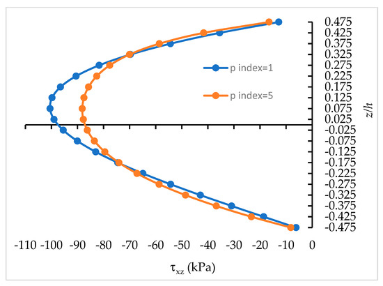
Figure 5.
Distribution of total transverse shear stress τxz across the thickness.
In this work, the variation through the thickness of FGM is approximated considering a certain number of virtual layers (20 layers in the present work). All the quantities are obtained at the middle of each layer, including the stresses. The upper and lower surfaces correspond to = 0.5 and = −0.5, respectively, where the shear stresses are zero. However, as mentioned above, the first and last virtual layers are obtained at the middle of these layers, i.e., = 0.475 and = −0.475.
5.2. Nonlinear Analysis of Hinged and Clamped FGM Cylindrical Panels under a Center Point Load
Two FGM cylindrical shell panels (Figure 6), one with the straight sides simply supported (hinged) and the curved sides free and the other with all sides clamped, are analyzed in this subsection. The geometry is defined by the following: R = 2.54 m, L = 0.508 m, and subtended angle 2 = 0.2 rad, H = 0.0127 m, and it is modelled by 392 triangular finite elements. The constituents are ZrO2 and Ti–6Al–4V with the following mechanical properties, respectively: = 168.0 × 10⁹ N/m2, = 0.298, ρc = 5700 kg/m3, = 105.7 × 10⁹ N/m2, = 0.298, ρm =4429 kg/m3. For this case of geometry and the boundary conditions of the cylindrical panel, the snap-through can occur. The results obtained using the present model for the transverse displacement paths are shown in Figure 7a,b and Figure 8a,b, respectively, for the hinged cylindrical panel and for the clamped cylindrical panel. These analyses have been validated in Moita et al. [11], although for different geometry and material properties. It is observed from the paths obtained for the hinged cylindrical panel that the snap-through does occur, while for the clamped FGM panels, the snap-through does not occur. Additionally, as expected, the displacements increase when the gradient index increases, considering that > . Considering the same cylindrical panel with both boundary conditions, but under radial pressure load, the corresponding load-displacement paths are shown in Figure 7b and Figure 8b.

Figure 6.
Cylindrical shell panel geometry and loadings.
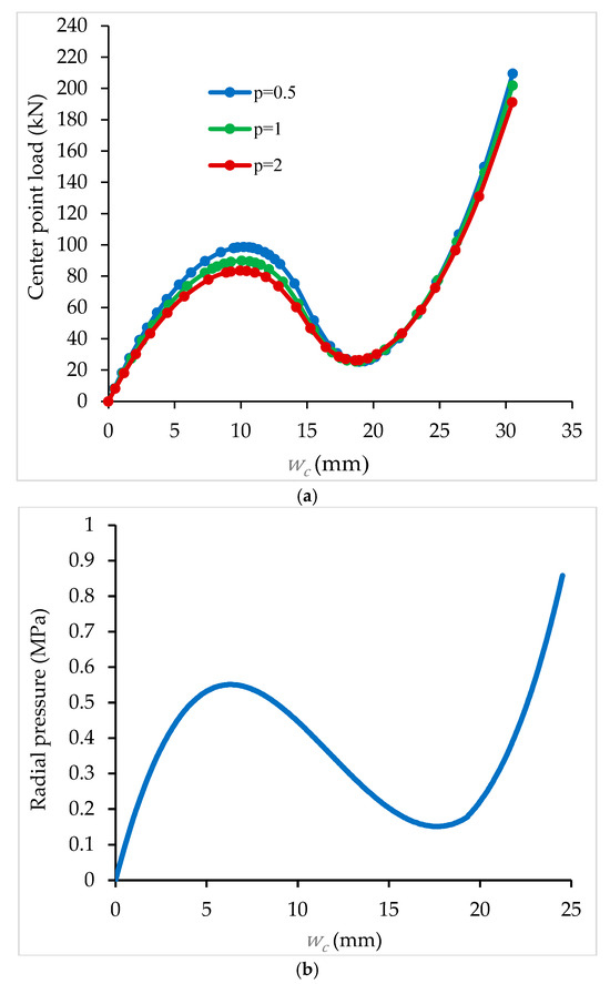
Figure 7.
(a) Load-displacement paths for the hinged cylindrical panel under point load. (b) Load-displacement paths for the hinged cylindrical panel under radial pressure load (p = 1).
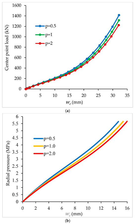
Figure 8.
(a) Load-displacement paths for the clamped cylinder panel under center point load. Inflection point at 140 kN for p = 1. (b) Load-displacement paths for the clamped cylinder panel under radial pressure load. Inflection point at 2.25 MPa for p = 1.
5.3. Critical Loads of a Clamped FGM Square Plate under Uniaxial In-Plane Applied Load
The linear buckling loads are obtained first in order to know which values should be considered for the calculations of the free vibrations under uniaxial in-plane applied load.
For the purpose of comparison, a square (a × a) FGM plate with all the edges movable and clamped, made of a mixture of zirconia and aluminum (Al/ZrO2), is considered. The material properties for the zirconia and aluminum are, respectively, = 151.0 × 10⁹ N/m2, , = 70.0 × 10⁹ N/m2, and ; the side dimensions are a = 0.2 m and thickness H = 0.01 m. The FGM plates are under uniaxial compression, and the power law index-p ranges from full ceramic to metal. The critical buckling parameters, defined as , with , are shown in Table 1. From this table, an excellent agreement between the results (for the first mode) obtained is observed with the present model (PM) compared with those obtained by Nguyen-Xuan et al. [21] using the MITC4 model and by Pham et al. [13]. For benchmarking purposes, the eigenvalues of some higher modes are also presented. Again, as Ec > Em, there is a decrease in the buckling loads when the p-index increases.

Table 1.
Non-dimensional buckling loads for plates with movable and clamped edges and different gradient indexes, with a/H = 20.
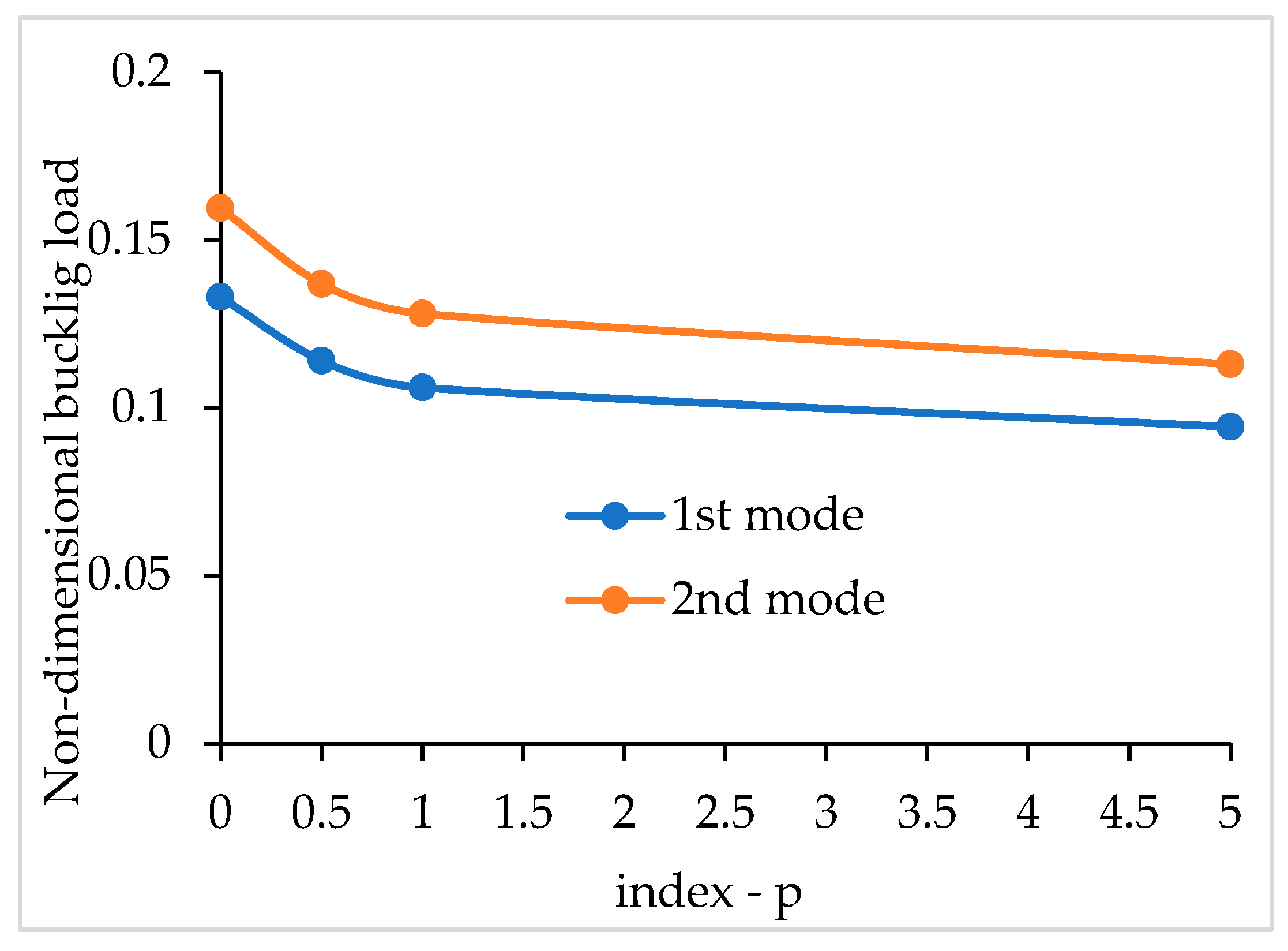
For comparison purposes, a square FGM plate with all edges movable and clamped is considered, but now with H = 0.01 m and sides with lengths of a = 1.0 m. The material properties are the following: = 380.0 × 10⁹ N/m2, , = 70.0 × 10⁹ N/m2, . The FGM plates are under uniaxial compression, and the power law index-p ranges from full ceramic to metal. The critical buckling parameter is now defined as , and the results obtained with the present model (PM) are compared in Table 2 with the alternative solutions for the first mode, obtained analytically by Wu et al. [22] using the first-order shear deformation theory. Figure 9 shows the variation of the non-dimensional buckling loads with the gradient index p.
Table 2.
Non-dimensional buckling loads for square plates with clamped edges and different gradient indexes, with a/H = 100.

Figure 9.
Variation of the non-dimensional buckling loads versus the gradient index p for a clamped plate with immovable edges.
5.4. Free Vibrations of a Simply Supported FGM Square Plate
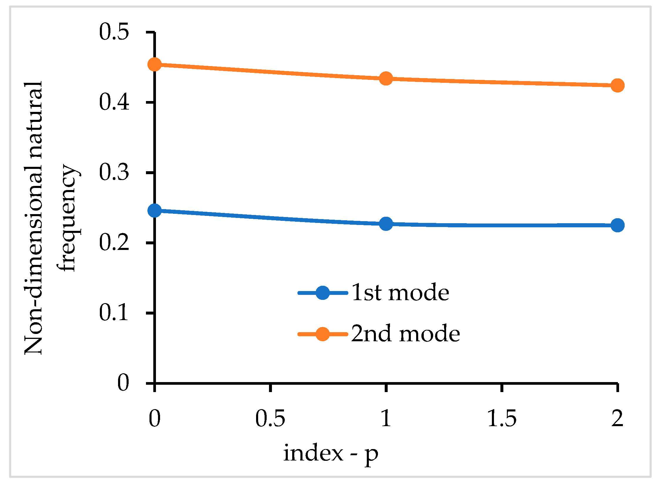
The free vibrations of a simply supported FGM square plate are now investigated. The material properties for the zirconia and aluminum are, respectively, the following: = 151.0 × 10⁹ N/m2, , ρc = 5700 kg/m3, and = 70.0 × 10⁹ N/m2, , ρm = 2702 kg/m3. The side dimension is a = 0.05 m, and the thickness is H = 0.01 m. The non-dimensional frequencies obtained with the present model (PM) are presented in Table 3 and compared with the alternative solutions obtained by Tran et al. [6] using a NURBS-based isogeometric approach and an HSDT model. For pure ceramic and pure metal, the results are very similar. The discrepancies between the results for the FGM plates are attributed to the different homogenization considered by Tran et al. [6] following the Mori–Tanaka scheme, while the present model uses the rule of mixtures. The corresponding graphical representation of the non-dimensional frequencies obtained by the present model is presented in Figure 10 for vibration modes 1 and 2.
Table 3.
Non-dimensional frequencies for simply supported plate with different gradient indexes.
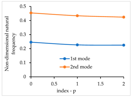
Figure 10.
Variation of the non-dimensional frequency of the simply supported plate versus the gradient index p.
The next investigation is to achieve how the free vibrations of an FGM plate with all the edges clamped and a power law index p = 1.0 are affected by two types of loading: the in-plane loading and transverse loading. The material properties are as follows: = 380.0 × 10⁹ N/m2, , ρm = 3000 kg/m3, = 70.0 × 10⁹ N/m2, , ρm = 2702 kg/m3. The geometry is defined by a = 1.0 m and H = 0.01 m. The results obtained are given in Table 4a–c. First, the free vibrations are calculated for the unloaded plate, and afterwards, for the three cases of loading:
Table 4.
(a) Natural frequencies [Hz] for a fully clamped plate under different types of loading (p = 1). (b) Natural frequencies [Hz] for a fully clamped plate under different types of loading (p = 1). (c) Natural frequencies [Hz] for a fully clamped plate under different types of loading (p = 1).
- (a)
- Uniaxial in-plane uniform load from px = 0 to a final px = 2.0, 4.0, and 10.0 MPa, and the geometrically nonlinear behavior is considered;
- (b)
- Transverse uniform load from pz = 0 to a final pz = 20.0, 40.0, and 60.0 kPa;
- (c)
- Uniaxial in-plane uniform load combined with transverse uniform load, ranging from zero to the previously defined magnitudes.
Here, is uniformly distributed pressure applied at the lower surface of the plate with the positive direction of z. is pressure applied at the edge with the positive direction of x axis, in the usual way. In this context, will be a concentrated load applied to the center of the plate aligned with the positive direction of axis z.
From Table 4 a–c, it is seen that the uniform compressive loading decreases the natural frequencies, while the uniform transverse pressure increases the natural frequencies. In addition, it is observed when both types of loads are applied, the first frequency increases, but less so than when only the transverse pressure is applied, and the other frequencies increase or decrease depending on the values of two types of loadings. In addition, it is shown that the size of the decreasing/increasing of frequency is directly connected with the increase of the loading.
By analyzing the stiffness parameter for the plates, it can be verified that for the simply supported plate with axial pressure, , the stiffness parameter decreases, and for a uniform transverse pressure, , the stiffness parameter increases. For the clamped plate with axial pressure, , the stiffness parameter decreases, and for a uniform transverse pressure, , the stiffness parameter increases.
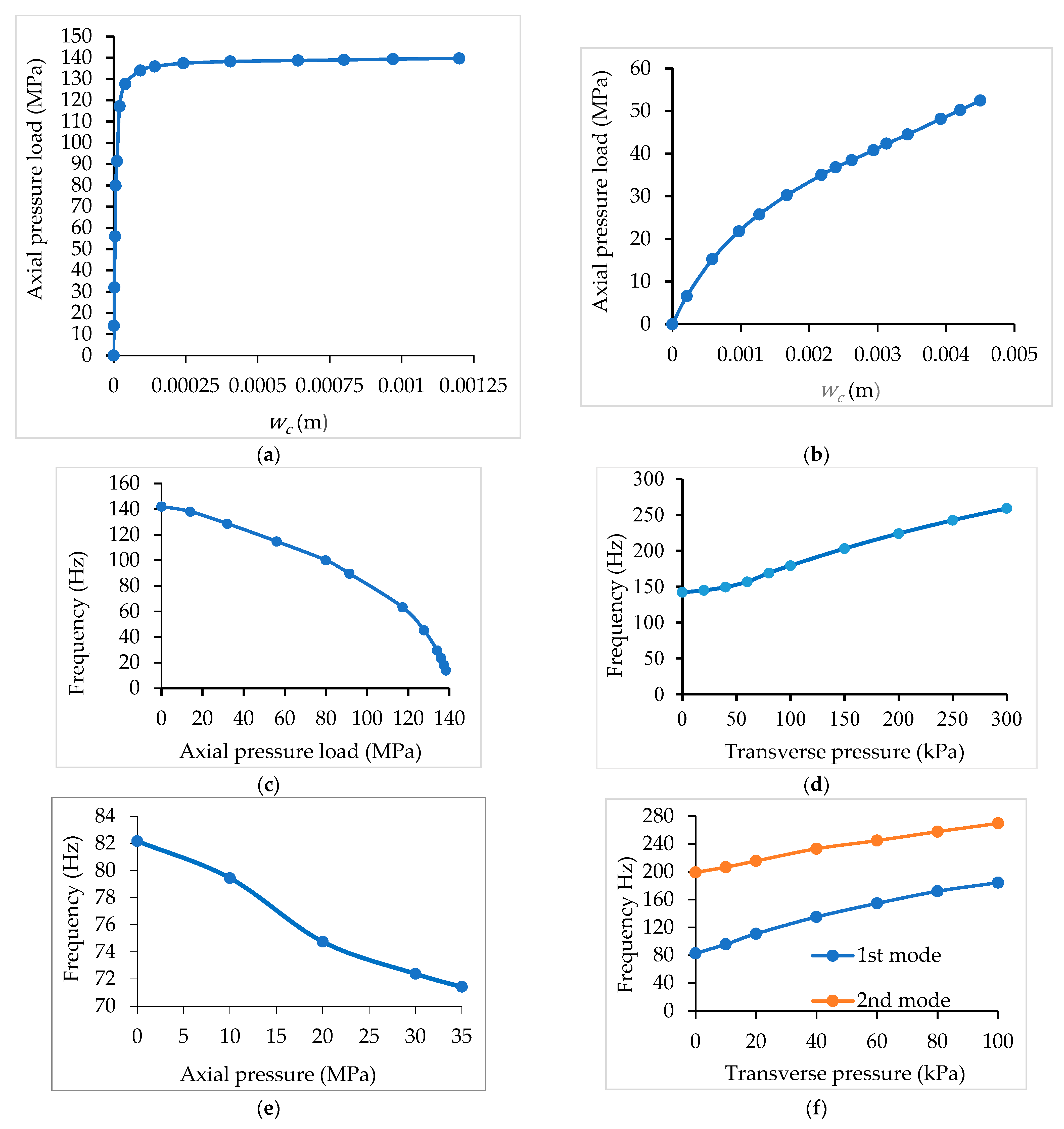
As for the cases of center point load and transverse pressure load, in Figure 11a,b, the load-displacement paths for the case of axial pressure loads applied to clamped and simply supported plates are presented. For the case of the clamped plates, an imperfect initial plate is considered, which consists of, in general, an initial center displacement .
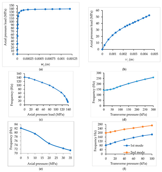
Figure 11.
(a) Load-displacement path for the clamped plate. (b) Load-displacement path for the SSSS plate. (c) Clamped plate under px. (d) Clamped plate under pz. (e) Simply supported plate under px. (f) Simply supported plate under pz.
From Figure 11a, it is observed that the minimum stiffness occurs for the load level of 138 MPa for the clamped plate, corresponding to the nonlinear buckling, and from Figure 11b, an inflection point near the load level of 35 MPa is observed.
Considering the gradient index p = 1.0, the variation of the fundamental frequency versus applied type load is shown in Figure 11c,d for the case of the clamped plate. The variations match accordingly with Table 3 and Table 4. Proceeding in the same way, the influence of magnitude and the type of applied loads on the fundamental frequency of simply supported plates with all the edges restrained in u and v displacements is shown in Figure 11e,f. The free vibration frequencies of the first and second modes are influenced by the magnitude and type of loading, as shown in Figure 11f, for the case of the simply supported plate.
From Figure 11c–f, it can be verified that the variation of the fundamental frequency of the simply supported and clamped plates decreases as the stiffness of plate decreases under increasing axial pressure. For the case of transversal uniform pressure, the fundamental frequency of the simply supported and clamped plates increases due to the increasing plate stiffness with the increase of transverse pressure.
5.5. Critical Loads of Hinged and Clamped FGM Cylindrical Panels under Uniaxial Compression
To validate the present model, a buckling analysis of a square FGM panel made of a mixture of aluminum and zirconia with the following properties is considered: = 70.0 × 10⁹ N/m2, = 0.3, = 151.0 × 10⁹ N/m2, = 0.3. The geometry of the panel is as follows: length L = 0.1 m, angle 2θ = 0.2 rad, radius R = 0.5 m, and thickness h = 0.1 m. The FGM panel is assumed to have the curved edges fixed and the straight edges simply supported (FSFS). The panel is under uniaxial compression applied on the curved edges. A 20 × 20 finite element mesh is used (800 triangular elements). The results of the first three buckling load parameters are given in Table 5a for the different power law indexes considered. From Table 5a, a good agreement with the results obtained by Zhao and Liew [23] is observed for the first buckling load, but with discrepancies varying from 4.5% to 9.5% for the second and third buckling loads, respectively. These discrepancies can be related to the different models—HSDT and a classical finite element used by present model, and FSDT and a mesh-free method used by Zhao and Liew.
Table 5.
(a) The critical buckling load of an FGM cylindrical panel under uniaxial compression and FSFS boundary conditions. (b) Non-dimensional buckling loads for the hinged cylindrical panel with different gradient indexes. (c) Non-dimensional buckling loads for the clamped cylindrical panel with different gradient indexes.
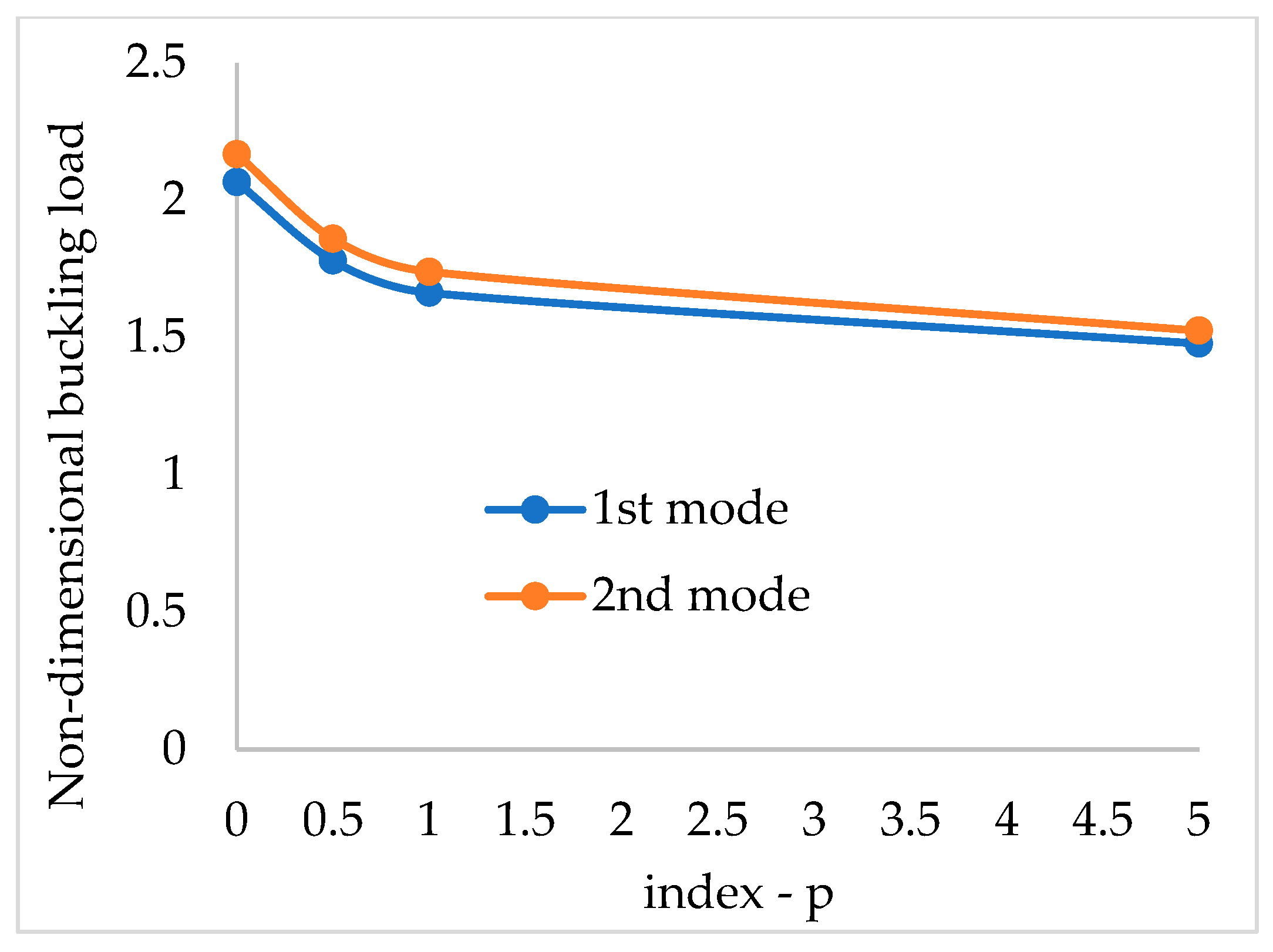
Hinged and clamped FGM cylindrical shell panels are now considered to obtain the critical loads. The geometry and mechanical properties are the same as in Section 5.2. The results for the non-dimensional buckling loads, , obtained using the present model, are shown in Table 5 b,c, and it is observed that decreases when the gradient index p increases. This happens because Ec > EFGM > Em. The corresponding graphic representation is shown in Figure 12 and Figure 13, respectively.
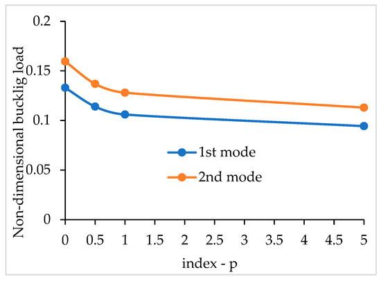
Figure 12.
Variation of the non-dimensional buckling loads versus the gradient index p for a hinged cylindrical panel.
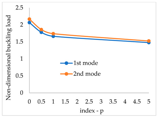
Figure 13.
Variation of the non-dimensional buckling loads versus the gradient index p for a clamped cylindrical panel.
5.6. Free Vibrations of Hinged and Clamped FGM Cylindrical Panels
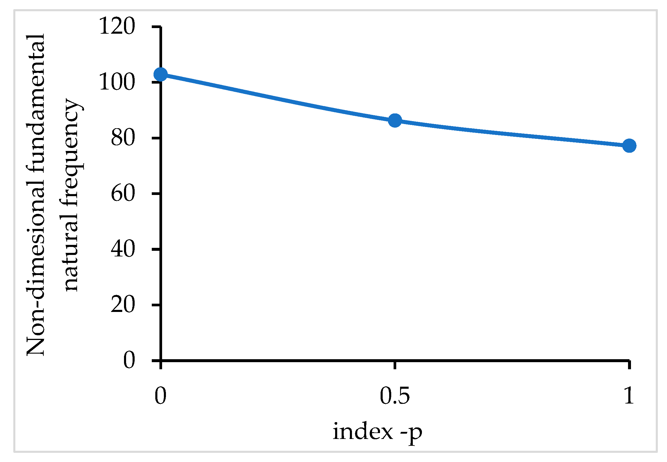
First, for comparison purposes, we utilized a clamped FGM cylindrical panel with the following geometry: R/10, a/h = 100, Ec = 380.0 × 10⁹ N/m2, , ρc = 3000 kg/m3, Em = 70.0 × 10⁹ N/m2, , ρc = 2707 kg/m3. The non-dimensional fundamental frequency is given by , with . The results obtained with the present model are presented and compared in Table 6, with good agreement, with the alternative solutions of Pradyumna and Bandyopadhyay [24] obtained using a higher-order formulation and a C0 finite element and the solutions published by Neves et al. [25] obtained using a higher-order shear deformation theory and radial basis functions. The graphical representation of the non-dimensional fundamental frequency versus the p-index is presented in Figure 14.
Table 6.
Non-dimensional fundamental frequency for the clamped cylindrical panel with different gradient indexes.
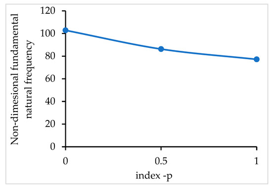
Figure 14.
Variation of the non-dimensional frequency versus the gradient index p for a clamped cylindrical panel.
The natural vibrations of the hinged and clamped FGM cylindrical shells from Section 5.2, with the same geometry and material properties, are now analyzed. The first three natural frequencies are obtained for the initial geometry (unloaded panel) considering different gradient indexes p. Next, the cylindrical panel is loaded by three kinds of loads. The applied loads produced displacements—new geometry—and a stress distribution over the plate/shell structure, which depends on the gradient index p. The new geometry and the state of stresses, which influences the stiffness of the structure at each load level, both have an influence on the values of the natural frequencies. In Table 7 a,b, Table 8 a,b and Table 9 a,b, the first three natural frequencies are shown for different gradient indexes. The graphic representation of the influence of applied loads on the fundamental frequency is shown in Figure 14 for the gradient index p = 1. The loadings are defined in Figure 6.
Table 7.
(a) Natural frequencies [Hz] for hinged FGM cylindrical panel, considering different gradient indexes and loading types. (b) Natural frequencies [Hz] for hinged FGM cylindrical panel, considering different gradient indexes and loading types.
Table 8.
(a) Natural frequencies [Hz] for clamped FGM cylindrical panel, considering different gradient indexes and loading types. (b)Natural frequencies [Hz] for clamped FGM cylindrical panel, considering different gradient indexes and loading types.
Table 9.
(a) Natural frequencies [Hz] for clamped FGM cylindrical panel, considering different gradient indexes and loading types. (b) Natural frequencies [Hz] for clamped FGM cylindrical panel, considering different gradient indexes and loading types.
- Hinged FGM panel loaded:
- (a)
- By a uniform pressure on the curved side, from py = 0 to a final = 20.0; 40.0 MPa. For this case of loading, the displacement v at y = L must be constrained to v = 0;
- (b)
- By a center point load, from = 0 to a final = 20.0; 40.0 kN;
- (c)
- By a uniform pressure on the curved side, from = 0 to a final = 20.0; 40.0 MPa, combined with a center point load, from = 0 to a final = 20.0; 40.0 kN.
The geometrically non-linear behavior is considered, and an incremental-iterative process is used. The results obtained with the present model are shown in Table 7 a,b. From these tables, the following can be observed:
- (a)
- The uniform compressive load minimally increases the first two natural frequencies but minimally decreases the third natural frequency.
- (b)
- The transverse center point load decreases the first three natural frequencies.
- (c)
- When both types of loads are applied, the first two frequencies decrease, but less than when only the center point load is applied.
- (d)
- It is shown that the frequencies decrease/increase more with the increase of the loadings.
- 2.
- Clamped FGM panel loaded:
- (a)
- By a uniform pressure on the curved side, from = 0 to a final = 25.0; 50.0 MPa;
- (b)
- By a center point load, from = 0 to a final = 20.0; 40.0 kN, or by an external radial pressure, form pr = 0 to a final pr = 2 MPa;
- (c)
- By a uniform pressure on the curved side, from = 0 to a final = 25.0; 50.0 kPa, combined with a center point load, from = 0 to a final = 20.0; 40.0 kN, or combined with an external radial pressure, from = 0 to a final = 1 MPa; 2 MPa.
The corresponding results are shown in Table 8 a,b and Table 9 a,b. From Table 8 a,b, the following is observed:
- (a)
- The uniform compressive load, the center point load, and the radial pressure load decrease the first three natural frequencies.
- (b)
- When any two types of loads are applied, the first three frequencies decrease much more.
- (c)
- It is shown that the frequencies decrease more with the increase of the loadings.
By comparing Table 9 a,b, it is observed that the external radial pressure decreases the natural frequencies more than the center point load and uniform compressive load, as well as their combinations.
Analyzing the stiffness parameter for the cylindrical panels, it can be verified that for the cylindrical hinged panel, subject to an axial pressure on the free curved edge, , the stiffness parameter decreases. For a central point load, , the stiffness parameter decreases, and for a uniform radial pressure, , the stiffness parameter decreases. For the clamped panel subject to an axial pressure on the curved edge, , the stiffness parameter decreases. For a central point load, parameter decreases, and for a uniform radial pressure, parameter decreases.
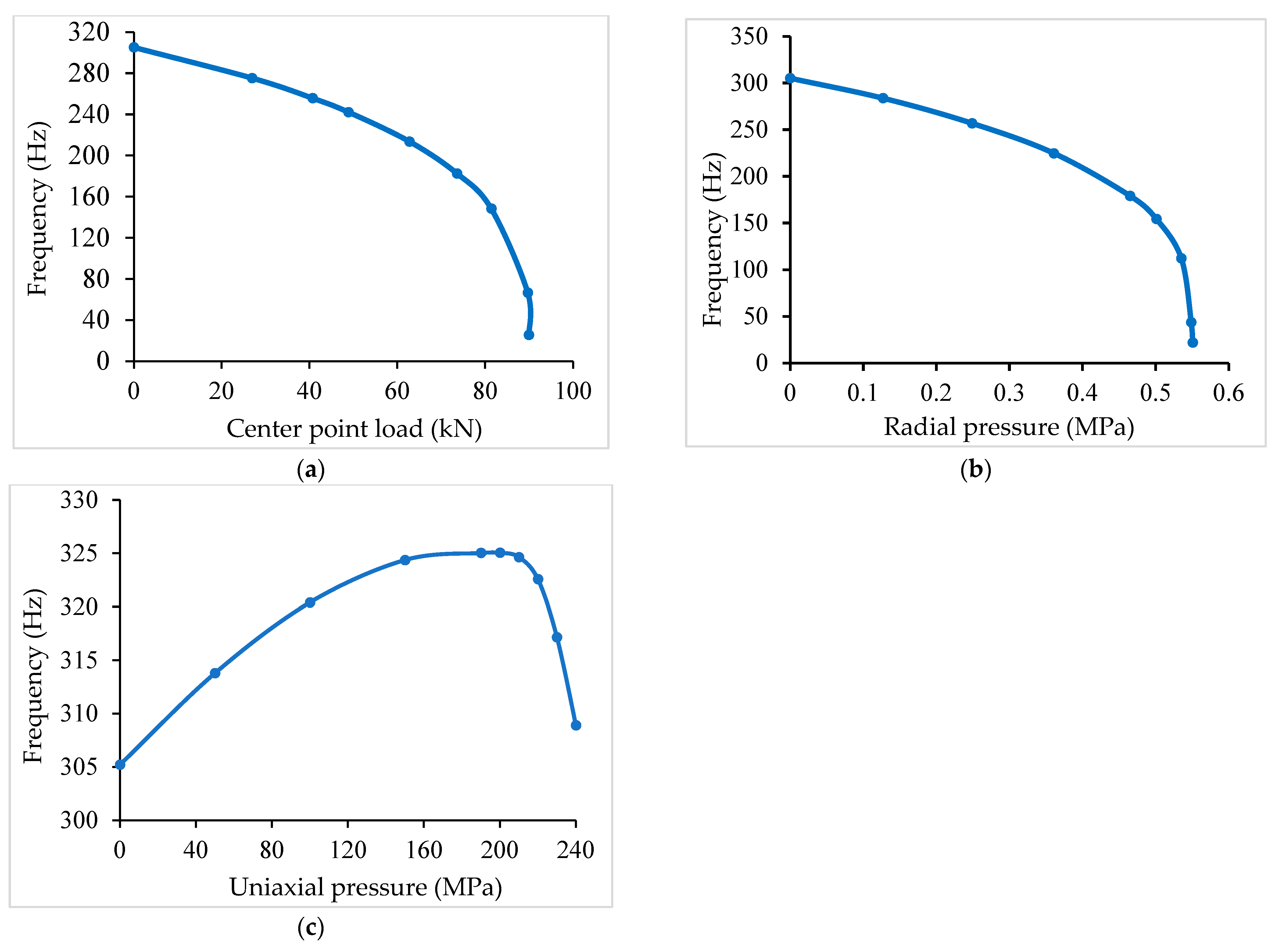
Considering the gradient index p = 1.0, the variation of the fundamental frequency versus applied type load and boundary conditions is shown in Figure 15a–c for the case of hinged cylindrical panels, and Figure 16a–c for the case of clamped cylindrical panels.
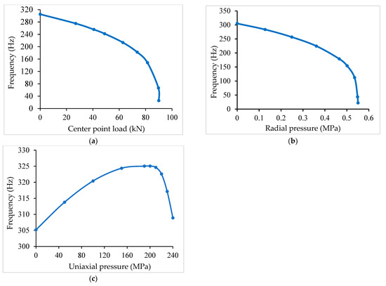
Figure 15.
(a) Hinged cylindrical panel. (b) Hinged cylindrical panel. Limit load: 89.92 KN. Limit load: 0.55 MPa. (c) Hinged cylindrical panel.
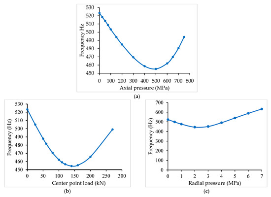
Figure 16.
(a) Clamped cylindrical panel. (b) Clamped cylindrical panel. (c) Clamped cylindrical panel. Inflection point at 140 kN. Inflection point at 2.25 MPa.
For the case of the hinged panel subjected to a center point load or radial pressure, the stiffness decreases, thus the fundamental frequency decrease is very low when the center point load is very close to the limit load. Observing Figure 15c, the fundamental frequency of the hinged shell panel increases under the axial pressure load, although the stiffness decreases, which can be attributed to the effect of the deformed shape on the frequency. For the uniaxial pressure, linear buckling has been achieved at 279.6 MPa. However, using the nonlinear analysis, the maximum transverse displacement is obtained at 200 MPa. At this pressure, the panel has the highest natural frequency.
For the axial compression load applied to the clamped cylindrical panel, shown in Figure 16a, the stiffness decreases and the fundamental frequency decreases under axial pressure load until the inflection point. For the same clamped cylindrical panel subjected to a center point load or a radial pressure load, the stiffness decreases, thus the frequency decreases until the inflection point.
6. Conclusions
A finite element model for the free vibration analysis of functionally graded material plate/shell panels under mechanical loading is presented. The loading is achieved by an incremental-iterative process to consider the geometrically nonlinear deformation of the structures.
The finite element model is based on Reddy’s third-order shear deformation theory applied to a non-conforming flat triangular plate/shell element with three nodes and eight degrees of freedom per node.
From the present applications, it is observed that the FGM plate/shell structures have a smooth variation of stresses through the thickness, and the free vibrations are influenced by the applied loads.
For the clamped and simply supported (with immovable edges) FGM plates, the uniaxial compressive pressure load leads to a decrease in the natural frequencies, while the uniform transverse pressure load leads to an increase in the frequencies. For the clamped FGM cylindrical panels, both types of loads lead to a decrease in the natural frequencies of the free vibration. In contrast, for the hinged FGM cylindrical panels, a uniform uniaxial compressive load leads to an increase in the first two frequencies, while the center point load and radial pressure load decrease the first three frequencies.
From these observations, it can be concluded that loads applied to plate/shell FGM structures can have significant impact on the natural frequencies, depending on the magnitude of the loads, the type of the applied loads, the boundary conditions, and the gradient index p.
In this work, only the gradient index p = 1 has been considered to build the numerical cases that show the influence of the applied loads on the fundamental frequency of plates and cylindrical panels (Figure 11c–f, Figure 15a–c and Figure 16a–c). It is observed that the stiffness is related to the frequency at each load level. In the case of the hinged cylindrical panel, the deformed shape seems to have an important role in influencing the frequency.
In future work, in order to develop a more comprehensive study, the effect on the variation of natural frequencies of higher modes (as shown in Figure 11f) with an arbitrary p-index could be studied. The present work provides results that can be used as a benchmark for interested readers to compare with new or available alternative theories in the development of new finite element models for FGM plate and shell structures with general geometry.
Author Contributions
Conceptualization, J.S.M.; methodology, J.S.M.; software, J.S.M.; validation, J.S.M.; formal analysis, all authors; investigation, all authors; resources, all authors; data curation, J.S.M.; writing—original draft preparation, J.S.M. and V.F.C.; writing—review and editing, V.F.C.; supervision, C.M.S.; project administration, C.M.S. All authors have read and agreed to the published version of the manuscript.
Funding
This work was funded by FCT, Fundação para a Ciência e Tecnologia, through IDMEC, under LAETA, project UIDB/50022/2020.
Data Availability Statement
The raw data supporting the conclusions of this article will be made available by the authors on request.
Acknowledgments
The authors dedicate this paper to the memory of Professor Rolands Rikards (1942–2022), who sadly passed away on 2 February 2022. He was a world academic and distinguished researcher expert in the fields of characterization of material properties, multidisciplinary optimization, solid mechanics, finite element techniques, advanced composite materials, and computational methods. We extend our condolences to his wife and family, his colleagues at Riga Technical University, and his friends in Latvia.
Conflicts of Interest
The authors declare no conflicts of interest.
References
- Woo, J.; Meguid, S.A. Nonlinear analysis of functionally graded plates and shallow shells. Int. J. Solids Struct. 2001, 38, 7409–7421. [Google Scholar] [CrossRef]
- Reddy, J.N.; Arciniega, R.A. Free vibration analysis of functionally graded plates. In Analysis and Design of Plated Structures: Dynamics; Woodhead Publishing: Cambridge, UK, 2006. [Google Scholar]
- Arciniega, R.A.; Reddy, J.N. Large deformation analysis of functionally graded shells. Int. J. Solids Struct. 2007, 44, 2036–2052. [Google Scholar] [CrossRef]
- Kim, K.D.; Lomboy, G.R.; Han, S.C. Geometrically nonlinear analysis of functionally graded material (FGM) plates and shells using a four-node quasi-conforming shell element. J. Compos. Mater. 2008, 42, 485–511. [Google Scholar] [CrossRef]
- Zhao, Z.; Liew, K.M. Geometrically nonlinear analysis of functionally graded shells. Int. J. Mech. Sci. 2009, 51, 131–144. [Google Scholar] [CrossRef]
- Tran, L.V.; Ferreira, A.J.M.; Nguyen-Xuan, H. Isogeometric analysis of functionally graded plates using higher-order shear deformation theory. Compos. Part B Eng. 2013, 51, 368–383. [Google Scholar] [CrossRef]
- Thai, H.-T.; Kim, S.-E. A simple higher-order shear deformation theory for bending and free vibration analysis of functionally graded plates. Compos. Struct. 2013, 96, 165–173. [Google Scholar] [CrossRef]
- Natarajan, S.; Ferreira, A.J.M.; Bordas, S.; Carrera, E.; Cinefra, M.; Zenkour, A.M. Analysis of Functionally Graded Material Plates Using Triangular Elements with Cell-Based Smoothed Discrete Shear Gap Method. Math. Probl. Eng. 2014, 247932. [Google Scholar] [CrossRef]
- Yn, S.; Yu, T.; Bui, T.Q.; Nguyen, M.N. Geometrically nonlinear analysis of functionally graded plates using isogeometric analysis. Eng. Comput. 2015, 32, 519–558. [Google Scholar] [CrossRef]
- Moita, J.S.; Araújo, A.L.; Mota Soares, C.M.; Mota Soares, C.A.; Herskovits, J. Material and Geometric Nonlinear Analysis of Functionally Graded Plate-Shell Type Structures. Appl. Compos. Mater. 2016, 23, 537–554. [Google Scholar] [CrossRef]
- Moita, J.S.; Araújo, A.L.; Correia, V.F.; Mota Soares, C.M.; Herskovits, J. Higher-order finite element models for the static linear and nonlinear behaviour of functionally graded material plate-shell structures. Compos. Struct. 2019, 212, 465–475. [Google Scholar] [CrossRef]
- Long, N.V.; Tu, T.M.; Truong, H.K.; Hai, L.T.; Trang, V.T.T. Displacement-based and stress-based analytical approaches for nonlinear bending analysis of functionally graded porous plates resting on elastic substrate. Acta Mech. 2022, 233, 1689–1714. [Google Scholar] [CrossRef]
- Pham, V.V.; Nguyen, V.C.; Hadji, L.; Mohamed-Ouejdi, B.; Ömer, C. A comprehensive analysis of in-plane functionally graded plates using improved first-order mixed finite element model. Mech. Based Des. Struct. Mach. 2023. [Google Scholar] [CrossRef]
- Bao, G.; Wang, L. Multiple cracking in functionally graded ceramic/metal coatings. Int. J. Solids Struct. 1995, 32, 2853–2871. [Google Scholar] [CrossRef]
- Zienkiewicz, O.C. The Finite Element Method; McGraw-Hill: New York, NY, USA, 1977. [Google Scholar]
- Bathe, K.J.; Ho, L.W. A simple and effective element for analysis of general shell structures. Comput. Struct. 1981, 13, 673–681. [Google Scholar] [CrossRef]
- Bathe, K.J. Finite Element Procedures in Engineering Analysis; Prentice-Hall Inc.: Englewood Cliffs, NJ, USA, 1982. [Google Scholar]
- Moita, J.S.; Araújo, A.L.; Martins, P.G.; Mota Soares, C.M.; Mota Soares, C.A. Analysis of active-passive plate structures using a simple and efficient finite element model. Mech. Adv. Mater. Struct. 2011, 18, 159–169. [Google Scholar] [CrossRef]
- Crisfield, M.A. A fast incremental/iterative solution procedure that handles snap-through. Comput. Struct. 1980, 62, 13–55. [Google Scholar]
- Crisfield, M.A. Non-Linear Finite Element Analysis of Solid and Structures, Volume 1: Essentials; John Wiley & Sons: Chichester, UK, 1991. [Google Scholar]
- Nguyen-Xuan, H.; Tran, L.V.; Thai, C.H.; Nguyen-Thoi, T. Analysis of functionally graded plates by an efficient finite element method with node-based strain smoothing. Thin-Walled Struct. 2012, 54, 1–18. [Google Scholar] [CrossRef]
- Wu, T.-L.; Shukla, K.K.; Huang, J.H. Post-buckling analysis of functionally graded rectangular plates. Compos. Struct. 2007, 81, 1–10. [Google Scholar] [CrossRef]
- Zhao, X.; Liew, K.M. A mesh-free method for analysis of the thermal and mechanical buckling of functionally graded cylindrical shell panels. Comput. Mech. 2010, 45, 297–310. [Google Scholar] [CrossRef]
- Pradyumna, S.; Bandyopadhyay, J.N. Free vibration analysis of functionally graded curved panels using a higher-order finite element formulation. J. Sound Vib. 2008, 318, 176–192. [Google Scholar] [CrossRef]
- Neves, A.M.A.; Ferreira, J.M.; Carrera, E.; Cinefra, M.; Roque, C.M.C.; Jorge, R.M.N.; Soares, C.M.M. Free vibration analysis of functionally graded shells by a higher-order shear deformation theory and radial basis functions collocation, accounting for through-the-thickness deformations. Eur. J. Mech. A Solids 2013, 37, 24–34. [Google Scholar] [CrossRef]


Disclaimer/Publisher’s Note: The statements, opinions and data contained in all publications are solely those of the individual author(s) and contributor(s) and not of MDPI and/or the editor(s). MDPI and/or the editor(s) disclaim responsibility for any injury to people or property resulting from any ideas, methods, instructions or products referred to in the content. |
© 2024 by the authors. Licensee MDPI, Basel, Switzerland. This article is an open access article distributed under the terms and conditions of the Creative Commons Attribution (CC BY) license (https://creativecommons.org/licenses/by/4.0/).