Article

Experimental and Numerical Analysis of a Temporary Bridge Connector Consisting of an Upper Bearing Block–Lower Pin Configuration

1
School of Mechanical Engineering, Changwon National University, Changwon 51140, Republic of Korea
2
Research Center, STEELKOREA, Seoul 06028, Republic of Korea
3
School of Architecture, Changwon National University, Changwon 51140, Republic of Korea
*
Author to whom correspondence should be addressed.
Appl. Sci. 2024, 14(5), 2012; https://doi.org/10.3390/app14052012
Submission received: 15 January 2024 / Revised: 21 February 2024 / Accepted: 27 February 2024 / Published: 29 February 2024
(This article belongs to the Special Issue Smart Green Technology in Railway Engineering)

Abstract

:
In this study, the structural details of a hinge connection for steel girder segments were developed to improve the process of rapid and easy construction. In the connector developed in this study (referred to as the “speedBridge” hereafter), the compression load exerted on the upper flange is resisted by two bearing blocks in contact with each other, and the tensile force on the bottom flange is resisted by the hinge structure installed at the lower part of the steel girder. The structural behavior of the developed connection was investigated experimentally. It was shown that the developed connection details could develop an excellent connection plastic rotation of 5% rad without fracture. The test specimen developed initial stiffness in accordance with elementary beam theory for a supported beam. The maximum load reached 110% of the plastic moment of the beam. Finite element analysis was conducted to comprehend the load transfer path, and the results demonstrated that the hinge connection exhibited sufficient stiffness and strength, exceeding the bending capacity of the beam under tension without any signs of the failure modes considered in the design procedure.

1. Introduction

Recent climate extremes, such as typhoons, floods, and earthquakes, have emerged as significant natural disaster threats in most parts of the world, and over time in Korea, these natural disasters have damaged some bridges, isolating residential communities located in mountains and rendering the delivery of emergency relief supplies to these communities challenging. Therefore, the construction of temporary bridges becomes crucial for the prompt transportation of food and medical supplies to disaster-affected areas. Deployable bridges are the most suitable temporary bridges for emergency purposes, for which portability, quick assembly, and low maintenance costs are essential.
Various studies on temporary bridges have been published. Vincent Viscomi et al. [1] developed ATLSS (Advanced Technology for Large Structural Systems) to automate a beam-to-column assembly, which comprised a quick-connector- and cable-driven Stewart platform mounted on a crane. Ario et al. [2] designed a foldable and extensible aluminum-constructed temporary bridge using stress-based optimization techniques. Its prototype bridge, with a folded length of 1 m and an extended length of 5.2 m, could support the weight of three adults. Lederman et al. [3] studied a new type of lightweight scrolling arch bridge in the United States. The prototype model is 3 m long and 0.25 m wide. Motor-driven cable reels are utilized to control the retracting, stretching, and recovery of the bridge. The temporary bridge designed by Yeh et al. [4] was constructed quicker than culvert bridges, which are commonly used temporary bridges. Yang et al. [5] proposed a new type of structural connector with boltless assembly connections. The functionality of this connector was numerically and experimentally validated.
Increasing labor safety during erection and on-site work while decreasing the fabrication and erection times and the total cost of structures is challenging. Therefore, structural engineering solutions are required to develop joints for steel-frame buildings with improved fabrication and erection characteristics. This collaborative idea must transition from local production technology to industrialized or automated production; this results in connections termed “plug and play” [6,7,8,9]. The primary motivations for developing these innovative connection forms are as follows: (1) to improve fabrication procedures, that is, to automate the process of structural assembly, and (2) to eliminate dangerous erection practices by reducing the amount of human assistance required during construction. These new forms focus on incentivizing the mass production of joints and connections, automating structural assembly, and minimizing hazardous erection procedures. These structural components are connected using bolts and nuts on-site. The activities on-site necessitate substantial physical exertion from steel construction workers, who are not immune to risk. The measures required to facilitate labor and ensure worker safety are becoming increasingly expensive. The development of plug-and-play connections that can be implemented using remote-control techniques is crucial. If the characteristics of joints are considered during the design phase, the development of plug-and-play joints can ease the on-site work and reduce the overall construction costs. Note that, in a steel structure, about 50% of the total costs are associated with its connections, whereas approximately 90% of the costs are already determined during the construction detailing phase [6,10].
Recently, extensive research efforts on the finite element (FE) analysis of joints were carried out. El-Sisi et al. [11] developed a 3d FE model to investigate the stiffness and strength of the single- and double-lap bolted joints of composite plates in the early design stage. For the validation of this model, they examined the developed model against experimental and numerical results reported in earlier research. They discussed the stiffness, load transfer, and stress concentration on the joints from the FE results, and the effects of staggered patterns on the additional cracks were investigated. Atta et al. [12] performed a 3d FE analysis to investigate the failure stages of double-lap-bolted joints. Using comparisons of results from laboratory experiments in their research, they recommended that FE analysis and artificial neural networks trained using FE results can be good alternatives for predicting the mechanical behavior of double-lap bolted joints while reducing the costs required for experiments. Hosseini and Rahnavard [13] performed a detailed FE analysis considering welded and bolted joint connections to investigate the performance of collar rigid connections by using the commercial FE software ABAQUS 2021. Their numerical results were validated by detailed comparative studies with experimental results for the joints. A discussion of the cyclic behavior of the rigid collar joint indicated that the large collar joint will exhibit appropriate seismic behavior, have no plasticity, and not lead to local buckling. El-Sisi et al. [14] developed a local FE model to account for local strain and stress at rivet joints. Their FE model was combined with a global FE model and utilized to evaluate the internal stress field and fatigue life of an old steel bridge in Egypt for which the structural documents and drawings had been lost. Detailed modeling techniques for their FE model were found in the literature [15]. Given the high costs of FE-riveted joint models, they assumed that the backing plates below the angles should be ignored. Modeling the interaction between steel components is crucial in the finite element modeling of steel rigid collar connections. Extensive research has utilized surface-to-surface interactions to depict the interactions between steel components. To specify the tangential and normal characteristics of the contact between surfaces, the penalty method and hard contact are assumed, respectively. The Coulomb friction coefficient for steel-to-steel interactions has shown variations in the literature [16,17,18,19,20].
In this study, the structural details of a hinge connection for steel girder segments were developed to improve the fundamental challenges related to the welded and bolted field joints of steel girder segments while also ensuring applicability to rapid construction sites such as emergency bridges (referred to as the “speedBridge” hereafter). In the speedBridge, the load acting on the compression flange of the segment girder is resisted by two bearing blocks, whereas that on the tension flange is resisted by hinge structures installed at both ends of the lower flange of the steel girder. The performance of the hinge connection structure details of the speedBridge steel girder segment proposed in this study was tested experimentally. In addition, an inelastic finite element (FE) analysis was conducted to determine the stress distribution of the connection.

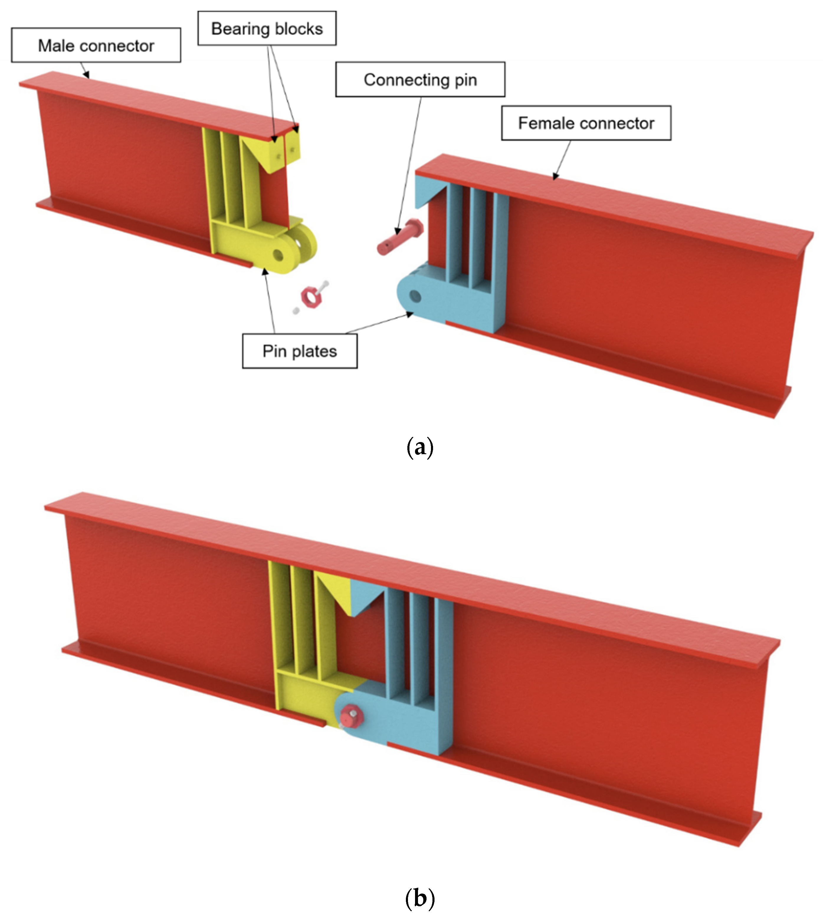
2. Concept of the speedBridge

The speedBridge developed in this study primarily comprises a hinge connection structure, which is located in the positive moment span to enable rapid construction. The connection part of the speedBridge comprises male and female connectors. Each connector consists of a bearing block that resists compression and pin plates that resist the tensile force caused by the pin (see Figure 1a). In the case of bearing blocks, the bearing plates are bolted through threaded rods to ensure stability in the coupling process of the connection part. In the case of pin plates, the pin is fastened to the part perforated in the pin plates (see Figure 1b). Moreover, in the process of composing the girder joint, the load transfer mechanism is clarified, and structural safety is ensured by introducing the bearing block to the upper part and a pin joint to the lower part.

3. Experimental Program

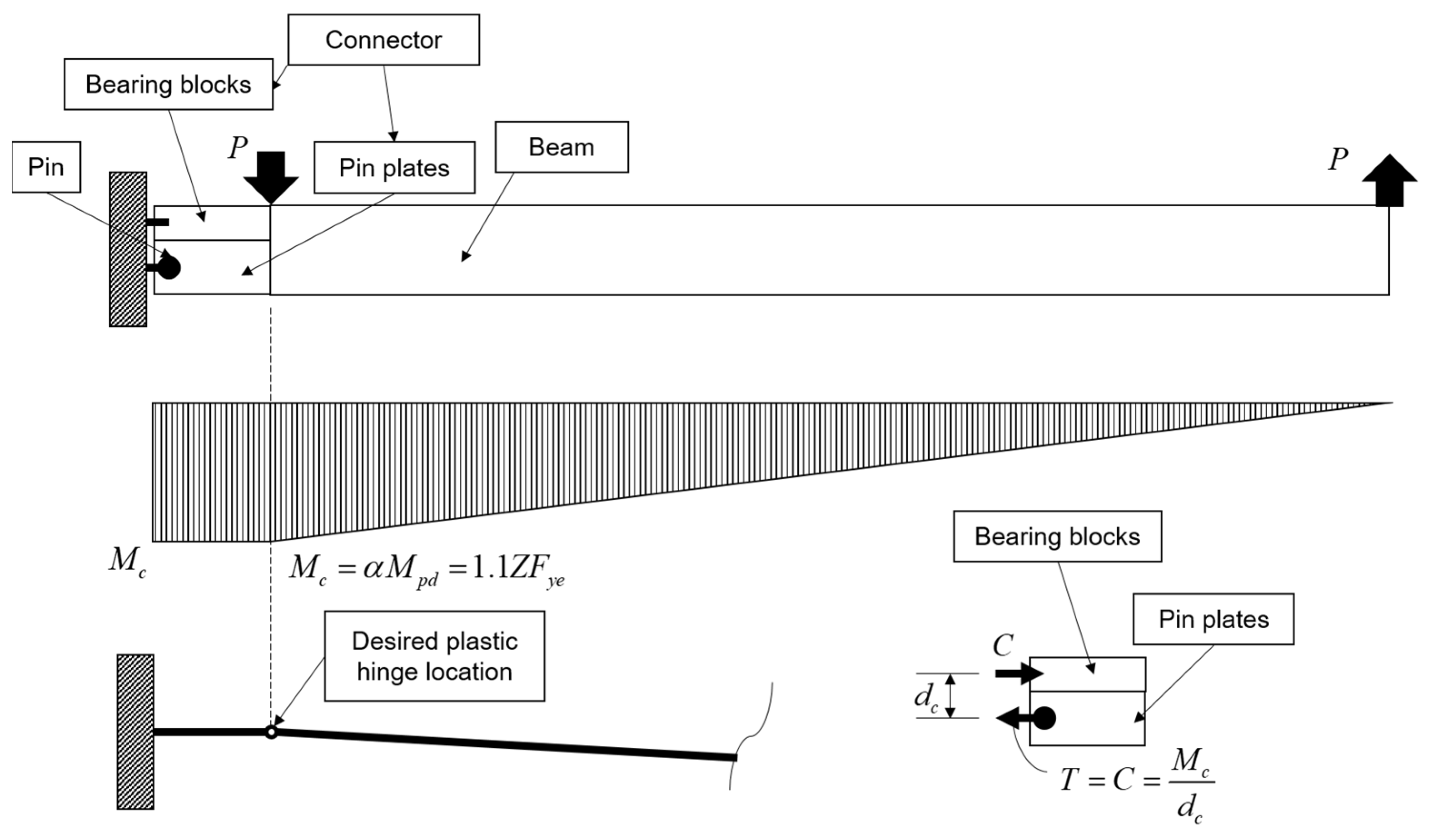
3.1. Design Procedure
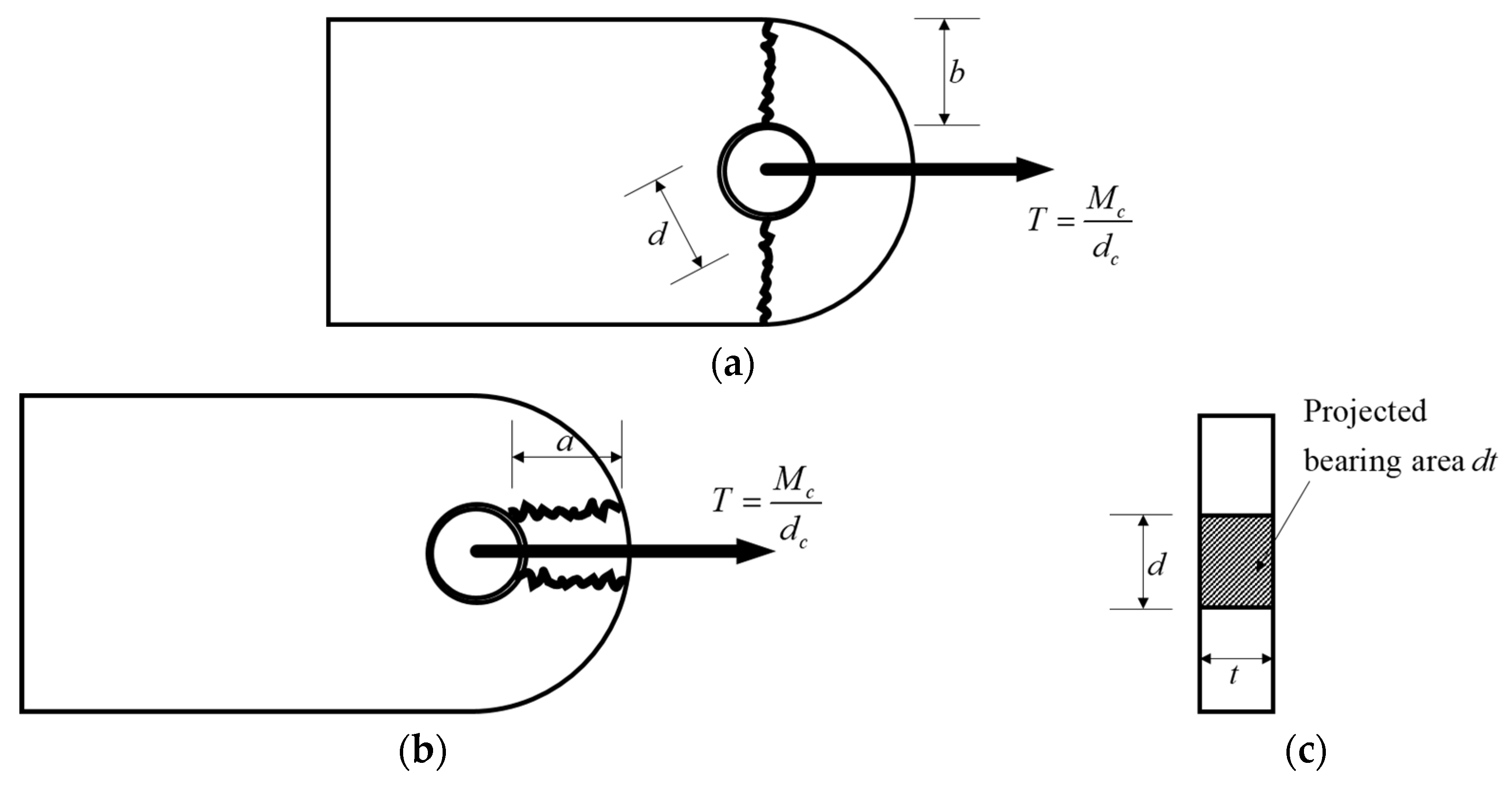
In the design of the speedBridge, a capacity design concept was adopted, such that the connection parts were designed to exhibit strength and stiffness comparable to or exceeding those of a beam without a hinge connection. Therefore, the moment resistance at the section where the pin exists needs to exceed the design plastic moment of the beam such that (see Figure 2)
M c α M p e = α Z F y e = α Z R y F y
where M c is the required moment resistance at the center of the connector, M p e is the expected plastic moment, Z is the plastic section modulus of the beam, F y e is the expected yield stress of beam flange, R y is the ratio of the expected yield stress to the specified minimum yield stress, F y is the specified minimum yield stress, and α is a number greater than 1.0 to account for the possible reserve strength of the steel beam beyond its nominal yield strength. In this study, α is taken as 1.1 to consider the hardening effect of the material. The factor R y is taken as 1.2, which is specified in the Korean Design Code for Seismic Design of Steel Structures [21].
The pin pulls the pin plates owing to the tension induced by the moment, and the tensile force is calculated according to the probable moment at the center of the connector, M c , and arm length, d c , as follows (see Figure 3):
T = M c d c
The details of the connectors were designed based on American Institute of Steel Construction (AISC) specifications [22]. In this design of pin plates, the AISC specification for pin-connected members was applied. The design strength of the connectors is determined by the tensile strength, ϕ P n , of the pin-connected members, and shall be the lower value determined according to the limit states of tensile rupture, shear rupture, bearing, and yielding (see Figure 3 for the fracture of pin plates). Moreover, in the design of the pin, the shear fracture and bearing of the pin were considered failure conditions.
The design considerations are summarized as follows:
  • Pin plates
(a) Fracture of net section (AISC Specification Section D5)
P n = F u 2 t b e , ϕ = 0.75
where b e = 2 t + 16   mm   b , with b being the actual distance from the edge of the hole to the edge of the part measured in the direction normal to the applied force, and F u is the specified minimum tensile stress of the pin plate.
(b) Longitudinal shear rupture (AISC Specification Section D5)
P n = 0.6 F u A s f , ϕ = 0.75
where A s f = 2 t a + d / 2 is the area of the shear failure, with a being the shortest distance from the edge of the pinhole to the edge of the member measured parallel to the direction of the force.
(c) Bearing of pin plates (AISC Specification Section J7)
P n = 1.8 F y A p b , ϕ = 0.75
where A p b = d t is the projected bearing area.
(d) Yield of the gross section (AISC Specification D2)
P n = F y A g , ϕ = 0.90
where A g is the gross area.
2.
Pin
(a) Shear failure (AISC Specification Section J3.6)
P n = 0.6 F u , p A p i n , ϕ = 0.75
(b) Bearing of the pin
P n = 1.8 F y , p A p b , ϕ = 0.75
where F y , p is the specified minimum yield stress of the pin, F u , p is the specified minimum tensile stress of the pin, A p i n is the area of the pin, and A p b is the projected bearing area of the pin.

3.2. Material Properties
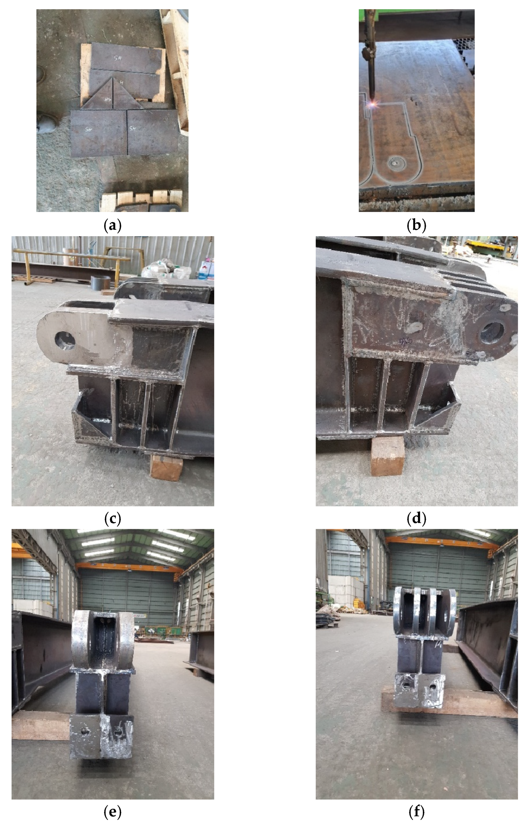
A series of material tensile tests were performed. The results are summarized in Table 1. According to the general requirements of steel structures in the Korean Design Standard [23], the minimum yield stress of SS275 steel is 275 MPa for plates 16 mm or less in thickness, 265 MPa for those exceeding 16 mm but less than or equal to 40 mm, and 245 MPa for those exceeding 40 mm but less than or equal to 75 mm. The minimum tensile stress of the SS275 steel is specified to be 410 MPa regardless of the thickness of the plate. By conducting tensile tests, the yield and tensile stresses of the steel used in this study were found to exceed the specified minimum stresses by approximately 20%, which is not significantly different from the overstrength factor considered in Equation (1).

3.3. Test Specimen

The overall view and details of the test specimen are shown in Figure 4. The total length of the beam was 8 m, the clear span was 7 m, and the distance between the loading points was 1 m (see Figure 4a,b). The flange and web of the beam, bearing blocks, and pin plates were made of SS275 steel, and the pin was made of SM45C steel. To prevent local buckling before reaching the ultimate strength, the beam was designed as a compact section (H-700 × 300 × 13 × 24). To prevent web crippling or local web yielding, stiffeners with 12t plates were welded to the support and at loading locations (see Figure 4c). Figure 4d,e show the sections for the female and male connectors, respectively. In these connectors, four plates of 30 mm thickness and two plates of 60 mm thickness were placed in the lower part of the connectors. To provide compressive forces, angle elements were located in the upper parts of the connectors, and the faces for bearing were connected with threaded rods (see Figure 4f). The detailed configuration of the connector is graphically shown in Figure 4g. Based on the design procedure specified in Section 3.1, the design strengths for the connector parts were calculated as summarized in Table 2. It can be stated that the governing failure mode is the longitudinal shear rupture of the pin plates.
Figure 5 shows the manufacturing process of the test specimen. First, the upper and lower flanges of the entire girder were cut to fit the size of the bearing plate and hinge connection parts. Subsequently, the plates required for the bearing blocks and pin plates were cut as designed, and the male and female connectors were designed. After the girder flange part of the hinge connection structure was welded, the girder web was cut to complete the segmented girder connection. Specimens were cut with a laser only from the flange of the H-beam steel (SS275) used to manufacture the specimens. The stiffeners were welded to the beam in a shop by a commercial fabricator.

3.4. Test Setup

Figure 6 shows the the setup. A four-point bending test was conducted to apply a moment exclusively between the central supports. LVDTs were installed at the midpoint and ends of the simply supported beam to measure the deflection and rotation angle.

4. Test Results and Discussion

4.1. Overall Behavior

Figure 7 depicts the force–displacement response of the test specimen. The speedBridge was capable of developing an excellent connection plastic rotation of 5% rad without fracture. The test specimen developed initial stiffness in accordance with elementary beam theory for a simply supported beam. The maximum load reached approximately 1600 kN, which corresponds to 110% of the plastic moment of the beam. After the maximum ultimate load was reached, the load-carrying capacity was reduced near a displacement of 225 mm by the lateral torsional buckling of the girder. Figure 8 shows the failure modes observed in the tests. Because of the loading, local buckling occurred on the top flange, and global buckling occurred on the outer side of the connection part. However, plastic deformation did not occur around the connection pin or connector parts. Moreover, the connecting pin was not damaged.

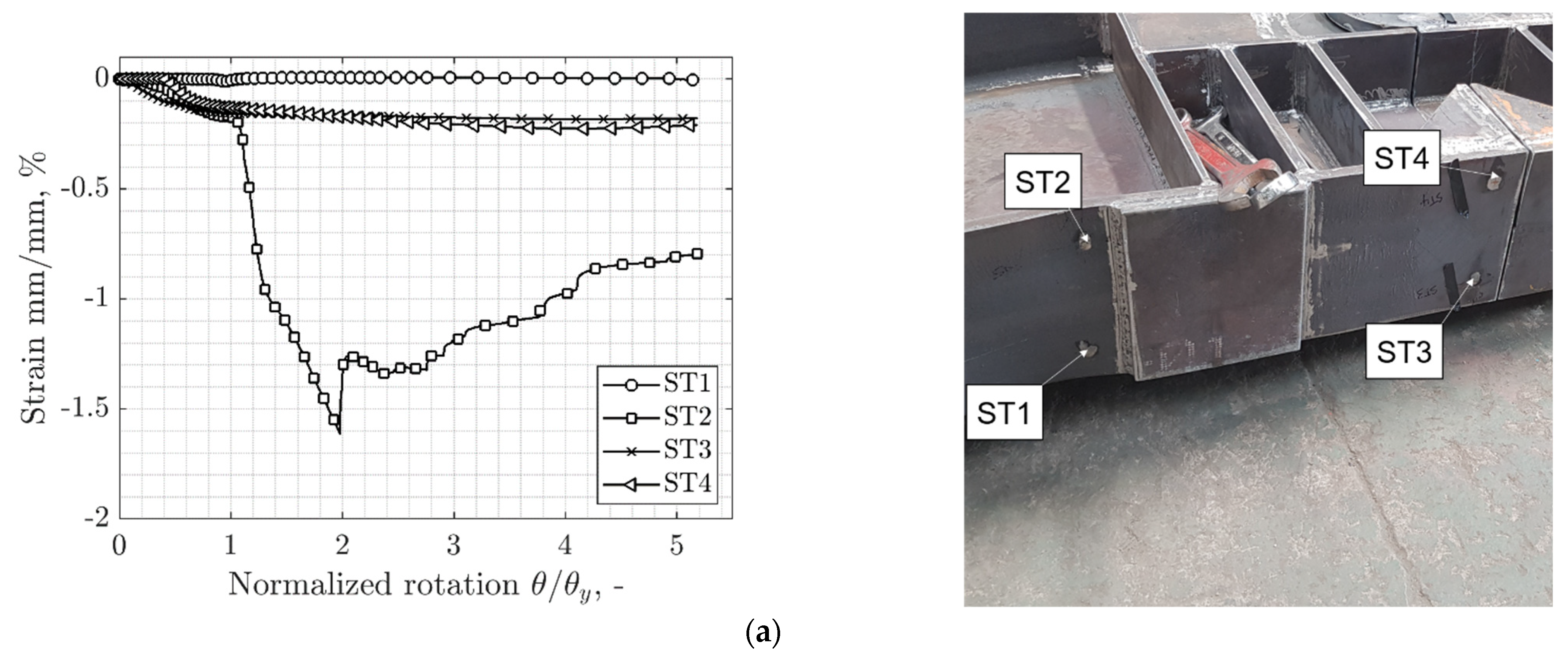
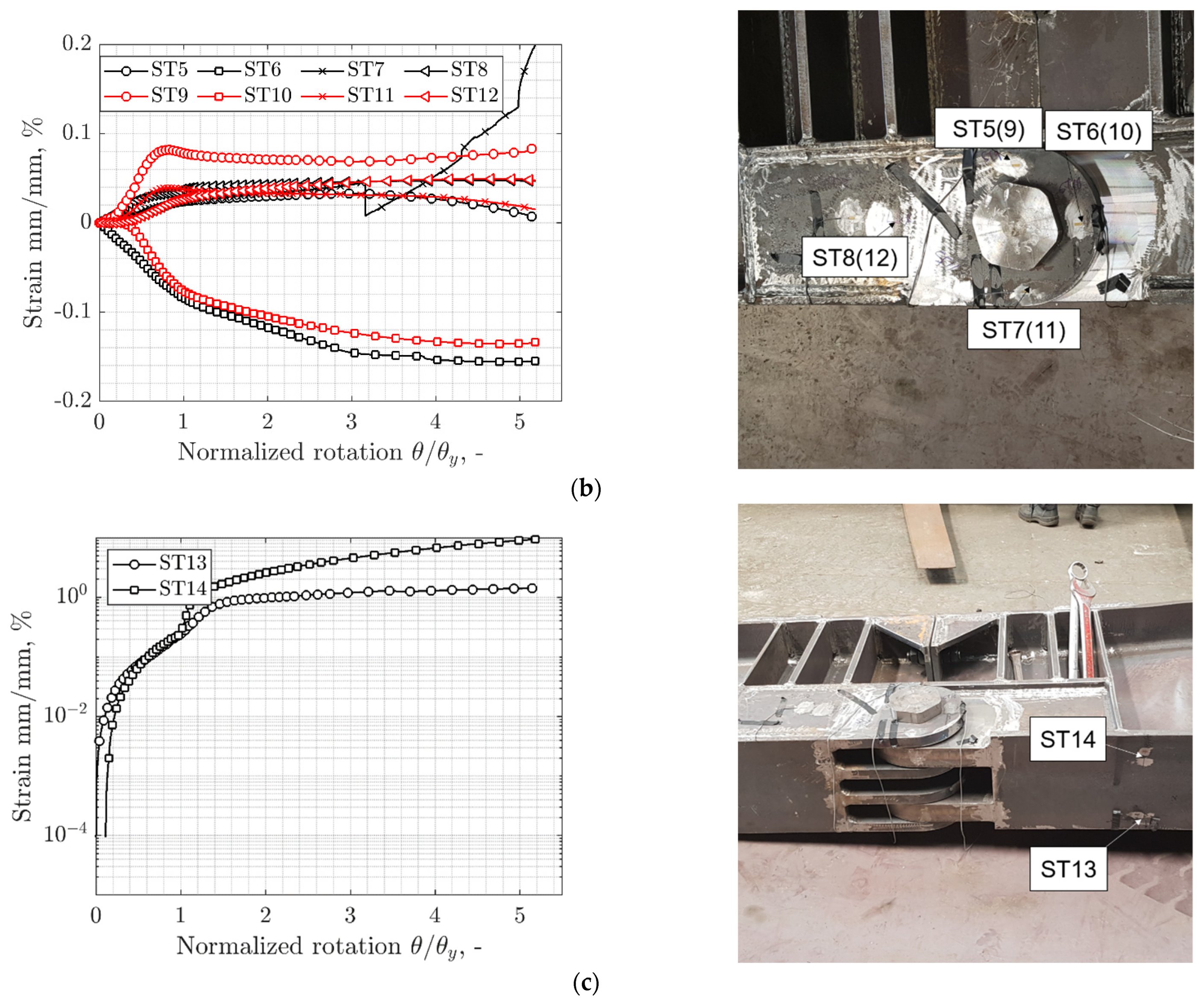
4.2. Strain Measurement
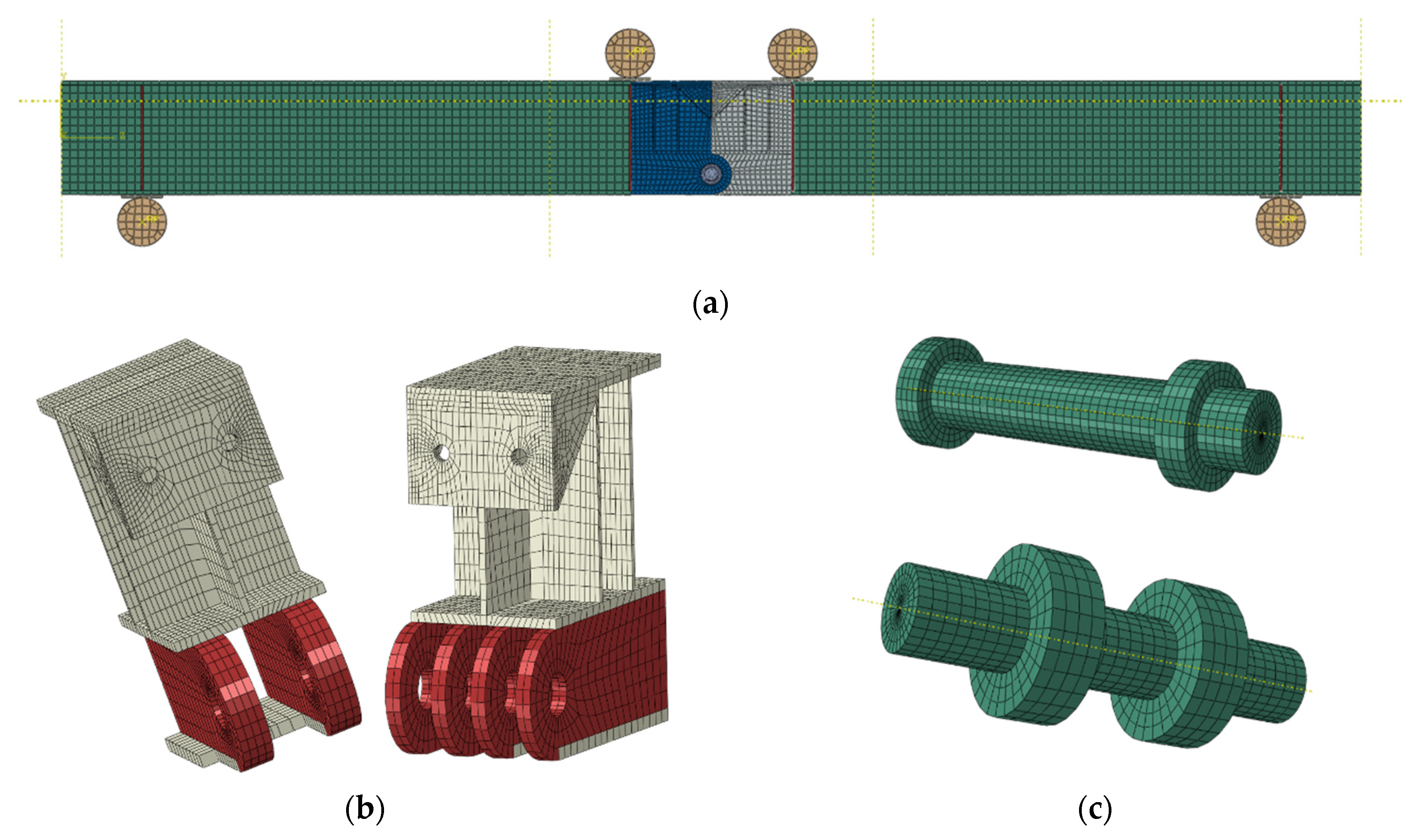
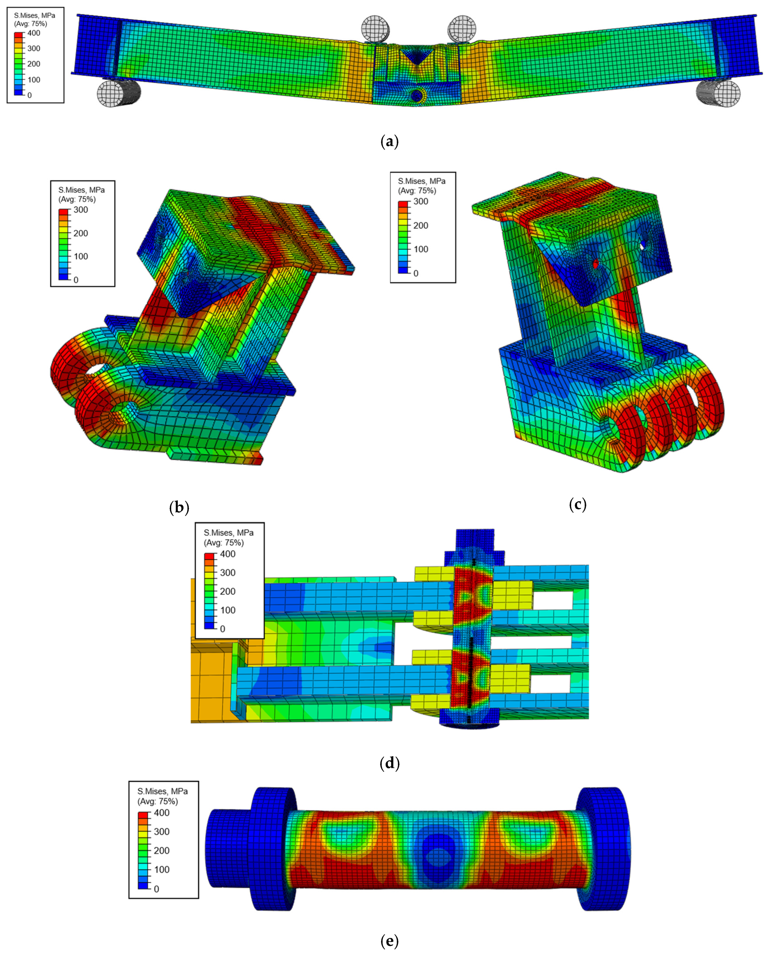
A total of 14 strain gauges were attached to the specimen surface to elucidate the overall behavior. Strain gauges labeled 1 to 4 were attached to the upper flange of the center of the beam, of which ST1 and ST2 were attached 10 cm away from the load point in the beam direction, and ST3 and ST4 were attached to the center of the connector where the bearing block was located. Figure 9a shows that the strain rate of ST2 changed rapidly owing to yield at the yield rotation angle and subsequent flange buckling, whereas, in ST1, no significant strain was observed during the experiment. This is presumed to be the effect of the torsion of the specimen in the process of manufacturing and loading the specimen. In the case of the upper flange of the beam at the upper part of the bearing block, yield strain was observed. However, as buckling was prevented by the side stiffeners of the block, no strain could exceed the yield strain.
Strain gauges ST5 to ST12 were attached to both sides of the female connectors among the pin plates, precisely at the bottom of the connectors. Notably, gauges could not be attached to the male connectors because these connectors were located between the female connectors and were not invisible. Figure 9b indicates that the elastic state was maintained such that the strains at none of the measured points reached 0.2%. Specifically, in the cases of ST5, ST9, and ST11, which were subjected to tension, the strains did not reach 0.1% and remained in the elastic state. In the cases of ST6 and ST10, which were expected to concentrate bearing stress, the strains did not reach the maximum value of 0.15%. Notably, ST8 and ST12, which were expected to transmit stress through tension, also exhibited negligible levels of strain. However, for ST5 and ST9, which were arranged on opposite sides, although the points were the same, the sizes were slightly different. This is because of the slight asymmetrical behavior exhibited owing to manufacturing errors. In the case of ST7, a sudden drop appeared at approximately three times the yield strain angle. Considering that no noticeable change was observed according to other strain values, the gauge was damaged.
Figure 9c shows the measurements from the strain gauges attached to the bottom flange, in which the ordinate has a logarithmic scale for readability. Herein, the bottom flange of the beam was deformed, even after yielding. Therefore, the stress was effectively transferred from the pin of the connector. A difference was observed in the post-yield region between the values of the two gauges. As confirmed by the abovementioned data, this difference was caused by the torsion of the specimen owing to manufacturing errors, etc.

4.3. FE Analysis

Further detailed analysis was conducted using FE analysis. The numerical modeling and analysis were performed using ABAQUS 2021 for the nonlinear inelastic analysis of developed structures [24]. Figure 10 shows the FE model used in this study. The FE mesh of the target structure was constructed using C3D8s (the nodes’ linear brick elements) to accurately predict the three-dimensional behavior of the structure. The stress–strain relationship of the steel used in the FE analysis was assumed to exhibit elastic–perfectly plastic bilinear behavior. The contact interface of the block and hinge connection was simulated using a small sliding contact element of ABAQUS. To define the tangential and normal characteristics of the contact between the surfaces, the penalty method and hard contact were assumed, respectively. In the FE model, a tangential friction coefficient of 0.3 was incorporated, as per the AISC specifications, specified for unpainted clean mill scale steel surfaces.
The mesh size varies in different areas of the model. The largest mesh size is 50 mm, which is used for beams and stiffeners in the area far from the connection region. The smallest mesh size is 5 mm, which is used for the bolts and the pin. A mesh sensitivity analysis was performed to obtain the optimal mesh size in the intersection area between the coarse and fine meshes. Hence, in this study, the authors used an overall mesh size of 30 mm in the intersection area (please refer to Figure 11). To apply boundary and load conditions more similar to the experimental conditions, the two lower rigid cylinders in Figure 10 were fixed in space, and a vertical displacement load was applied to the two upper rigid cylinders. Contact conditions were considered for all parts.
Figure 12 compares the moment–rotation relationship from the test result with that from the FEM result, superimposed. This figure shows that the FE model used in this study has sufficient accuracy to describe the overall experimental results. In the case of the analysis model, a sudden slip appears immediately at the beginning when the pin is in contact with the pin plates. For the subsequent behavior, the FE model exhibits greater stiffness than the experimental results; however, the overall strength is consistent. Strain data were also compared with the measurement values, which showed that the strain data measured in the pin plates remained in the elastic state at the measurement points, as intended in our design. Similarly, for the strain measured in the lower flange of the beam, we were able to obtain plastic deformation beyond the elastic limit as intended.
When considering the failure modes calculated in Table 2, the shear failure of the pin plate and the shear failure of the pin were the primary concerns. As anticipated, stress concentrations along the longitudinal direction of the pin plates and at the point where shear occurs in the pin were observed. Figure 13 illustrates the stress distribution based on the FE results. As depicted in Figure 13a, a plastic hinge forms where the beam is connected outside the connecting part. Additionally, within the connector parts, the applied moment at the mid-span of the beam is countered by stress concentration on the lower part of the pin plates and the upper part of the bearing blocks. Figure 13b,c detail the stress distributions of the male and female connectors, respectively. In the case of the bearing block, compressive stress is efficiently transferred to the upper flange of the beam through the upper flange and the web of connectors. Regarding the pin plates, both the male and female connectors withstand tensile forces, transferring stress from the periphery of the pin to the lower flange. Figure 13d presents a cross-sectional view of the connection between the pin plates and the pin, demonstrating the flow of stress at the junction. Figure 13e displays the stress distribution of the pin, revealing high stress levels around the surface in contact with the pin plates, although no significant damage was observed.

5. Summary and Conclusions

Modern industry necessitates innovative technologies that prioritize labor safety during construction, reduce fabrication and erection durations, and minimize overall project costs. In response to these needs, a novel solution was developed to enhance fabrication and erection characteristics. The fundamental concept of this innovative structure entails the compression load on the girder’s flange being supported by two bearing blocks while the tension load is transferred by the hinge part connected by pins at both ends of the lower flange of the steel girder. Through a combination of numerical simulations and experimental evaluations, the performance of this hinge connection structure, designated as the speedBridge steel girder segment, was evaluated. It is important to note that the study was limited to a single test because of prevailing conditions; however, plans are in place to conduct further experiments to ensure reliability. Nevertheless, to augment reliability within the specified conditions, finite element analyses were performed to elucidate the load transfer mechanisms.
The study yielded the following key findings:
(1)
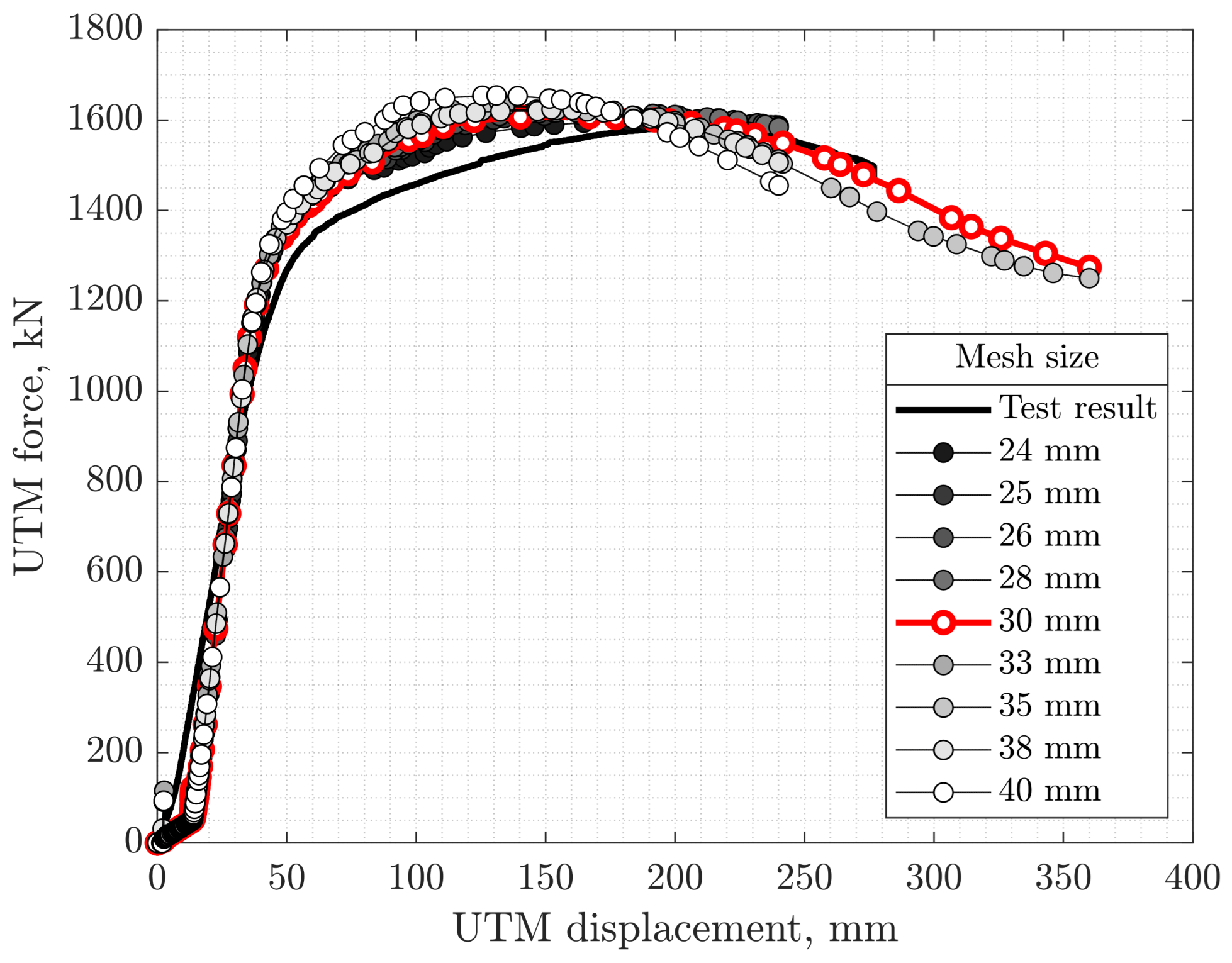
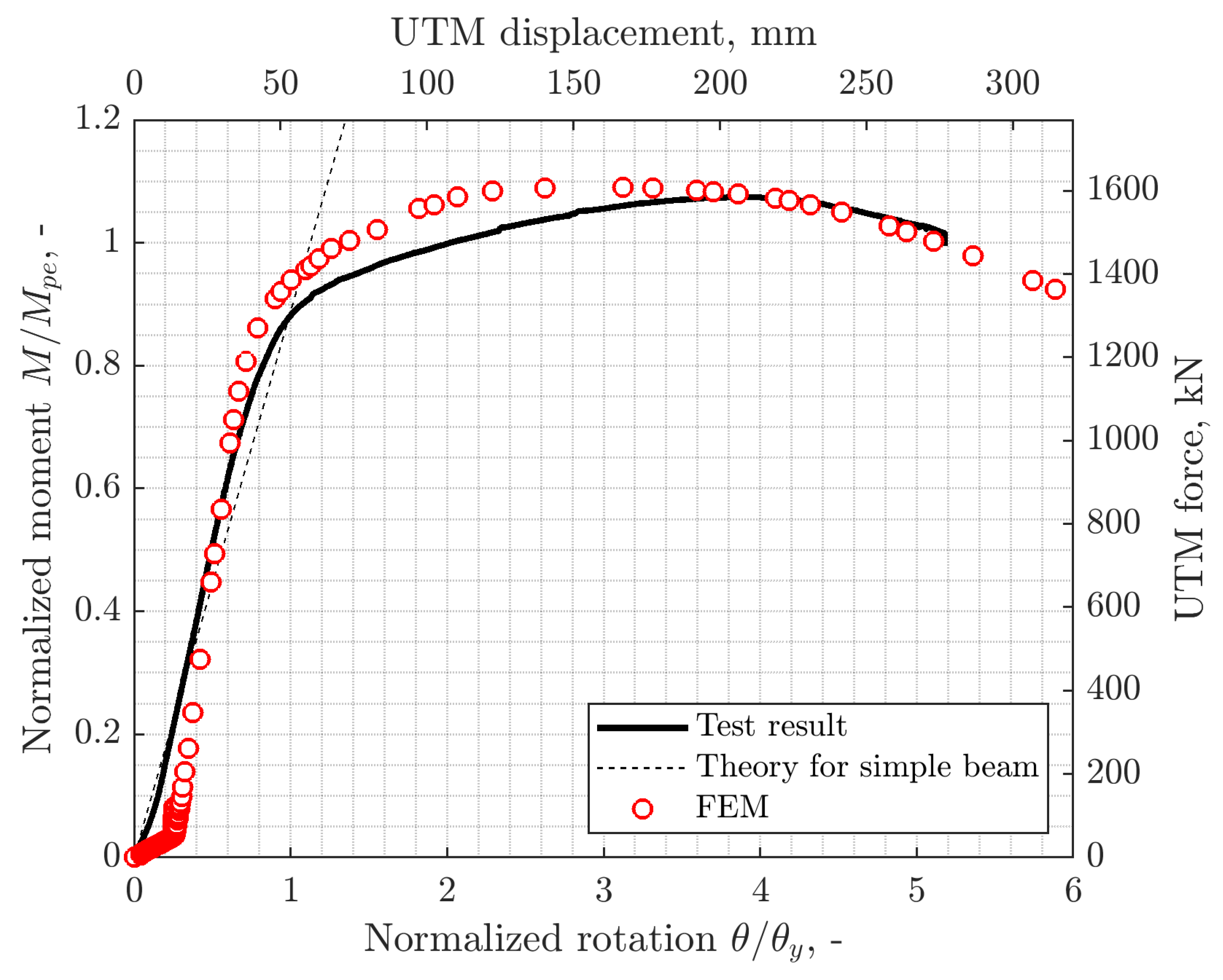
The speedBridge demonstrated the ability to achieve a plastic rotation of 5% rad without fracture. The test specimen exhibited initial stiffness consistent with elementary beam theory for a simply supported beam. Notably, the maximum load reached approximately 1600 kN, corresponding to 110% of the plastic moment of the beam. Following the attainment of the ultimate load, the load-carrying capacity diminished near a displacement of 225 mm because of lateral torsional buckling in the girder.
(2)
Compared with a single-segment girder, the entire girder exhibited stiffer initial load–displacement behavior and demonstrated more stable ductile behavior until succumbing to lateral torsional buckling failure under the ultimate load. Additionally, the ultimate load, at 1600 kN, surpassed the plastic moment of the girder, indicating an over-strength of approximately 10% or greater.
(3)
The failure modes of the specimen were primarily observed as yielding in the beam section. It was concluded that the pin plates, upper pins, and lower pins possess adequate strength and stiffness until the beam section reaches a fully plastic range. Local buckling was observed on the top flange, while global buckling occurred on the outer side of the connection part. However, these instances of local and global buckling had a negligible impact on the structural capacities of the speedBridge. No plastic deformation occurred around the connection pin or connector parts, and the connecting pin remained undamaged.
(4)
Finite element analysis was conducted to comprehend the load transfer path, and the results demonstrated that the hinge connection exhibited sufficient stiffness and strength exceeding the bending capacity of the beam under tension without any signs of the failure modes considered during the design procedure.

Author Contributions

H.-L.J. conducted the FEA and contributed to the analytical framework. C.-H.H. contributed to the detailed design of the test setup and specimen. R.-H.K. contributed to the fabrication of the test specimen. D.-Y.P. contributed to the conceptualization of the product. S.-Y.K. coordinated the research results of the collaborators during the writing of the manuscript and led the setting of the overall direction. All authors contributed to modifying this manuscript. All authors have read and agreed to the published version of the manuscript.

Funding

This paper was supported by the Changwon National University Research Fund in 2024.

Institutional Review Board Statement

Not applicable.

Informed Consent Statement

Not applicable.

Data Availability Statement

Data are within the article.

Acknowledgments

The authors thank the anonymous reviewers and editors for their valuable and constructive suggestions for improving this article.

Conflicts of Interest

Authors Chae-Hee Han, Ri-Ha Kim, Dae-Youl Park were employed by the company STEELKOREA. The remaining authors declare that the research was conducted in the absence of any commercial or financial relationships that could be construed as a potential conflict of interest.

References

  1. Viscomi, B.V.; Michalerya, W.D.; Lu, L.W. Automated construction in the ATLSS integrated building systems. Autom. Constr. 1994, 3, 35–43. [Google Scholar] [CrossRef]
  2. Ario, I.; Nakazawa, M.; Tanaka, Y.; Tanikura, I.; Ono, S. Development of a prototype deployable bridge based on origami skill. Autom. Constr. 2013, 32, 104–111. [Google Scholar] [CrossRef]
  3. Lederman, G.; You, Z.; Glišić, B. A novel deployable tied arch bridge. Eng. Struct. 2014, 70, 1–10. [Google Scholar] [CrossRef]
  4. Yeh, F.Y.; Chang, K.C.; Sung, Y.C.; Hung, H.H.; Chou, C.C. A novel composite bridge for emergency disaster relief: Concept and verification. Compos. Struct. 2015, 127, 199–210. [Google Scholar] [CrossRef]
  5. Yang, Y.Y.; Chang, C.M.; Kang, S.C.; Yeh, F.Y. Study of Construction-Oriented Structural Connectors for a Temporary Bridge. In Proceedings of the 36th International Symposium on Automation and Robotics in Construction (ISARC 2019), Banff, AB, Canada, 21–24 May 2019; Volume 36, pp. 1171–1175. [Google Scholar]
  6. Bijlaard, F.S.K.; Brekelmans, J.W.P.M. Joint Design for Economy and Verification Based on Eurocode 3. In Proceedings of the Sixth International Workshop. Presented at the Connections in Steel Structures VI, Chicago, IL, USA, 23–25 June 2008; pp. 7–17. [Google Scholar]
  7. Bijlaard, F.S.K.; Brekelmans, J.W.P.M. Plug and play type joints in steel and steel–concrete composite constructions: Development guide and design considerations. IES J. Part A Civ. Struct. Eng. 2008, 1, 237–256. [Google Scholar] [CrossRef]
  8. Bijlaard, F.S.K.; Coelho, A.M.G.; Magalhães, V.J.D.A. Innovative joints in steel construction. Steel Constr. 2009, 2, 243–247. [Google Scholar] [CrossRef]
  9. Brekelmans, J.W.P.M.; Bijlaard, F.S.K. Design requirements for plug and play type joints in mixed and steel-concrete composite construction. In Proceedings of the Proc 4th International Workshop Connections in Steel Structrures IV, Roanoke, VA, USA, 22–25 October 2000; pp. 63–70. [Google Scholar]
  10. Evers, H.; Maatje, I.F. Cost Based Engineering and Production of Steel Constructions. In Proceedings of the Fourth International Workshop. Presented at the Connections in Steel Structures IV: Behavior, Strength and Design, Roanoke, VA, USA, 22–25 October 2000; pp. 14–22. [Google Scholar]
  11. El-Sisi, A.E.D.; Sallam, H.E.D.; Salim, H.A.; El-Husseiny, O.M. Structural behavior of hybrid CFRP/steel bolted staggered joints. Constr. Build. Mater. 2018, 190, 1192–1207. [Google Scholar] [CrossRef]
  12. Atta, M.; Abd-Elhady, A.A.; Abu-Sinna, A.; Sallam, H.E.M. Prediction of failure stages for double lap joints using finite element analysis and artificial neural networks. Eng. Fail. Anal. 2019, 97, 242–257. [Google Scholar] [CrossRef]
  13. Hosseini, S.M.; Rahnavard, R. Numerical study of steel rigid collar connection affecting cyclic loading. Eng. Struct. 2020, 208, 110314. [Google Scholar] [CrossRef]
  14. El-Sisi, A.E.D.A.; El-Husseiny, O.M.; Matar, E.B.; Sallam, H.E.D.M.; Salim, H.A. Field-testing and numerical simulation of vantage steel bridge. J. Civ. Struct. Health Monit. 2020, 10, 443–456. [Google Scholar] [CrossRef]
  15. Sallam, H.E.M.; El-Sisi, A.E.A.; Matar, E.B.; El-Hussieny, O.M. Effect of clamping force and friction coefficient on stress intensity factor of cracked lapped joints. Eng. Fail. Anal. 2011, 18, 1550–1558. [Google Scholar] [CrossRef]
  16. Rezaeian, A.; Jamal-Omidi, M.; Shahidi, F. Seismic behavior of ConXL rigid connection in box-columns not filled with concrete. J. Constr. Steel Res. 2014, 97, 79–104. [Google Scholar] [CrossRef]
  17. Rahnavard, R.; Thomas, R.J. Numerical evaluation of the effects of fire on steel connections; Part 1: Simulation techniques. Case Stud. Therm. Eng. 2018, 12, 445–453. [Google Scholar] [CrossRef]
  18. Williamson, S.J.; Gorst, N.J.S. Friction in Temporary Works; HSE Books: Norwich, UK, 2013. [Google Scholar]
  19. Yang, C.; Yang, J.F.; Su, M.Z.; Liu, C.Z. Numerical study on seismic behaviours of ConXL biaxial moment connection. J. Constr. Steel Res. 2016, 121, 185–201. [Google Scholar] [CrossRef]
  20. Gumpertz, S. ConXtech-XL Collar Connection Model; Simpson Gumpertz & Heger Inc.: Waltham, MA, USA, 2007. [Google Scholar]
  21. KDS 14 31 60; Seismic Design of Steel Structures. Ministry of Land, Infrastructure and Transport: Sejong, Republic of Korea, 2022.
  22. AISC. Specifications for Structural Steel Buildings (360-16); AISC: Chicago, IL, USA, 2016. [Google Scholar]
  23. KDS 14 31 10; Design of Steel Structures. Ministry of Land, Infrastructure and Transport: Sejong, Republic of Korea, 2019.
  24. Smith, M. ABAQUS/Standard User’s Manual, Version 6.9; Simulia: Johnston, RI, USA, 2009. [Google Scholar]
Figure 1. Schematic of the speedBridge. (a) Before assembly; (b) After assembly.
Applsci 14 02012 g001
Figure 2. Capacity design of the speedBridge.
Applsci 14 02012 g002
Figure 3. Failure modes for pin plates. (a) Fracture of net section; (b) Longitudinal shear; (c) Bearing.
Applsci 14 02012 g003
Figure 4. Drawings of test specimen (all units in mm). (a) Top view; (b) Side view; (c) Section A-A; (d) Section B-B; (e) Section C-C; (f) Details of connector; (g) Connection.
Applsci 14 02012 g004
Figure 5. Manufacturing for connectors of the speedBridge. (a) Bearing blocks; (b) Pin plates; (c) Male connector (side view); (d) Female connector (side view); (e) Male connector (longitudinal view); (f) Female connector (longitudinal view).
Applsci 14 02012 g005
Figure 6. Test setup.
Applsci 14 02012 g006
Figure 7. Force–displacement response of tested beam.
Applsci 14 02012 g007
Figure 8. After testing the speedBridge. (a) Whole specimen; (b) Near pin connection; (c) Male connector; (d) Female connector; (e) Pin and connectors.
Applsci 14 02012 g008
Figure 9. Strain measurements. (a) Top flange; (b) Pin plate; (c) Bottom flange.
Applsci 14 02012 g009aApplsci 14 02012 g009b
Figure 10. FE model used in the analysis. (a) Overall; (b) Male connector (left) and female connector (right); (c) Upper pin (top) and lower pin (bottom).
Applsci 14 02012 g010
Figure 11. Mesh sensitivity analysis.
Applsci 14 02012 g011
Figure 12. Comparison of test result (solid line) and FE results (red dots).
Applsci 14 02012 g012
Figure 13. Stress distribution of FE model. (a) Overall; (b) Male connector; (c) Female connector; (d) Cut view of pin and connectors; (e) Pin.
Applsci 14 02012 g013
Table 1. Coupon labeling and material test results.
ElementGrade Yield   Stress   F y e , MPa Tensile   Stress   F t e , MPa Elongation %
Beam(1)SS27534750120.0
Beam(2)SS27535049829.4
Beam(3)SS27535650129.5
Beam(4)SS27534449730.2
Plate-12T(1)SS27534745732.0
Plate-12T(2)SS27536447231.0
Plate-12T(3)SS27534747231.0
Plate-20T(1)SS27530645231.0
Plate-20T(2)SS27530645231.0
Plate-20T(3)SS27529845532.0
Plate-30TSS27530448232.0
Plate-60TSS27532245236.0
Table 2. Nominal and design strengths of the connector parts.
ElementsFailure ModeNominal Strength, kNDesign Strength, kN
Pin platesFracture of net section85616421
Longitudinal shear rupture23911793
Bearing failure47523564
Yield of gross section14,85013,365
PinShear failure42243168
Bearing failure60484536
Disclaimer/Publisher’s Note: The statements, opinions and data contained in all publications are solely those of the individual author(s) and contributor(s) and not of MDPI and/or the editor(s). MDPI and/or the editor(s) disclaim responsibility for any injury to people or property resulting from any ideas, methods, instructions or products referred to in the content.

