Article

A Compact, Low-Profile, Broadband Quasi-Isotropic Antenna for Non-Line-of-Sight Communications

Department of Electrical Engineering, Chungnam National University, Daejeon 34134, Republic of Korea
*
Author to whom correspondence should be addressed.
Appl. Sci. 2024, 14(5), 2068; https://doi.org/10.3390/app14052068
Submission received: 17 January 2024 / Revised: 26 February 2024 / Accepted: 28 February 2024 / Published: 1 March 2024
(This article belongs to the Special Issue Antenna System: From Methods to Applications)

Abstract

:
A single-feed broadband quasi-isotropic antenna was designed for non-line-of-sight (NLOS) wireless sensor networks. The proposed antenna is based on a combination of fork-shaped crossed dipoles. It shows the broadband of quasi-isotropic radiation characteristics with high radiation efficiency. The electrical size ka of the proposed antenna is 0.94 with respect to its lower operating frequency. Its profile is also extremely thin at 0.0015λ. The impedance is matched from 1.8 to 4.3 GHz, or an 81.9% fractional bandwidth, whereas the maximum gain deviation ranging from 6.2 to 9.2 dB for the quasi-isotropic radiation is achieved from 1.8 to 3.6 GHz with a 10 dB criterion, which is close to the impedance bandwidth. The performance from the computed expectations is verified, as it shows a gain deviation of 8.4–9.8 dB from 1.9 to 3.3 GHz with an 80% fractional impedance bandwidth. The proposed antenna also shows good spatial coverage of circular polarization at high frequencies. Lastly, the received power level performance of the proposed antenna is tested under the NLOS condition, which shows a higher level compared to the linearly polarized, broadband omni-directional monopole antenna.

1. Introduction

Owing to the rapid growth in wireless technology and the miniaturization of devices, the demand for compact, broadband, and full-spatial-coverage antennas has become popular in respect to many applications, including wireless sensor networks, energy harvesting, Internet of Things (IoTs), and monitoring and radio frequency identification (RFID) systems [1,2,3,4,5,6,7,8]. However, such mission-critical wireless sensor network applications face challenges. First, in many realistic cases, the transmitting (Tx) and receiving (Rx) nodes cannot directly see each other due to the time-varying feature of mobile nodes and obstructions [2], representing the non-line-of-sight (NLOS) environment, as shown in Figure 1. Traditional networks offered noteworthy achievements using numerous techniques, such as spread spectrum, channel diversity, and time diversity. However, mission-critical control systems need reliable networks that surpass what existing networks can provide. The second issue is the need for frequency-hopping systems in wireless sensor networks, where the transmitter changes its carrier frequency to detect the signals from different channels and the interference during each hop [6]. This leads to a complex system requiring intricate and costly digital frequency synthesizers and an error detection mechanism. To overcome this, broadband operating antennas are preferred over narrow-band antennas. The need for batteries is the last, but not the least, predominant issue in regard to charging multiple devices in wireless sensor networks [9,10]. Indeed, many wireless sensor nodes are encountered in inaccessible or burdensome places. The maintenance of the battery remains challenging; currently, many technologies are being developed that will resolve the battery life limitations in wireless devices, such as the advancement of rechargeable batteries and the use of double-layer capacitors. In addition, the collection and conversion of ambient energy from diverse sources, including electromagnetic waves, vibration, and heat for energy harvesting technology, are being studied intensively [11,12]. Among these sources of energy, wireless energy harvesting has garnered significant attention due to the availability of several wireless signals such as cellular, satellite, and Wi-Fi.
To provide reliable and robust NLOS communications with less cumbersome wireless connections and battery-less sensors, it is desired for the antenna to operate in broad frequencies and radiate electromagnetic energy uniformly in all directions. Such uniform radiation characteristics could be obtained by an ideal isotropic source [13]; however, due to its non-existence nature [14], researchers instead showed a way to obtain a nearly uniform radiation pattern in the name of quasi-isotropic antennas [15,16,17,18,19,20,21,22,23,24,25,26,27,28,29,30]. These types of antennas can be achieved using radiation pattern synthesis, such as by a combination of electric and magnetic dipoles, a different orientation of dipoles, two electric dipoles with a 90° phase shift, etc. The performance of quasi-isotropic antennas is measured through the metrics of gain deviation, isotropic coverage, or beam width [15], and the practice of measuring the gain deviation is widely carried out. Gain deviation is defined as the difference between the minimum and maximum gains of the entire spherical radiating space.
The remarkable achievements of quasi-isotropic antenna designs so far are that they mostly operate in a narrow band [16,17,18,19] or in dual bands [20,21,22], and only very few of them show quasi-isotropic characteristics in broad frequencies [22,23,24,25,26]. In [23], an antenna made of a curved meandered dipole and two short-circuited strips was studied in an ultra-high-frequency (UHF) RFID band to provide a quasi-isotropic performance in a broad bandwidth of 20%. In [24], an inactive UHF RFID tag antenna was reported using two twisted dipoles and a modified double T-matching network with a maximum bandwidth of 8.5%. The antenna in [25] contained four consecutive revolved L-shaped monopoles fed by a compact uniform sequential-phase feeding network with an equal amplitude and an incremental 90° phase delay. The reported maximum bandwidth is 20.8%. For antenna-on-package (AoP) applications, a dipole antenna was folded along the edges of the package with the maximum impedance bandwidth of 32% while obtaining 18% spatial coverage of the circular polarization (CP) [26]. The desired quasi-isotropic radiation pattern was observed at 1.57 GHz. In [27], an inverted antenna-based RFID tag with an impedance bandwidth of 15% was reported.
It is worth noting that currently, there is no standard gain deviation for quasi-isotropic antennas in the literature, but it is usually in the range of 3 to 10.5 dB for single-frequency resonant antennas, whereas it is usually in the range of of 6 to 12.7 dB for wideband antennas [27]. Moreover, there are very few works on quasi-isotropic antennas with CP performance [26,29,30] in broad frequencies, despite its advantageous features in wireless systems, such as polarization mismatch mitigation and multi-path interference reduction [31,32,33].
In this paper, we propose an electrically small, low-profile, and highly efficient quasi-isotropic antenna that is matched over broad frequencies from 1.8 to 4.3 GHz, or 81.9%, while simultaneously providing the quasi-isotropic radiation pattern and CP characteristics. A quasi-isotropic pattern with a gain deviation ranging from 6.2 to 9.2 dB is observed from 1.8 to 3.6 GHz. The proposed antenna takes the crossed dipole configuration, and the working mechanism is examined with parametric studies. We use Ansys HFSS 2020 R2 for the full-wave electromagnetic (EM) simulations in this work, and the computed expectations are verified experimentally. Furthermore, the proposed antenna’s performance is verified in the university corridor NLOS environments to consider the applications of the wireless sensor network nodes and RF energy harvesting. Some preliminary results have been reported in [34].

2. Broadband Quasi-Isotropic Antenna Design

2.1. Crossed Dipole Antenna

The basic configuration of the proposed antenna is composed of two electric dipoles that are oriented perpendicularly along the x- and y-axes, as shown in Figure 2. In this antenna, the electric dipole oriented along the x-axis has maximum radiation in the yz-plane and null in the xz-plane, whereas the electric dipole oriented along the y-axis has maximum radiation along the xz-plane and null in the yz-plane. Therefore, a combination of the two dipoles can produce a quasi-isotropic radiation pattern [33]. This type of configuration is also widely used in the design of unidirectional CP antennas, where the directional radiation pattern is obtained with the reflectors [35,36,37,38,39].
Starting with this basic principle of the crossed dipoles, we design the proposed antenna, as shown in Figure 3. To achieve the quasi-isotropic radiation pattern using the crossed dipoles, the two electric dipoles necessarily have an equal amplitude and a 90° phase difference. Instead of using power dividers, feeding networks, or delay lines to meet the phase condition, we adopt phase delay curved lines, which are often referred to as vacant rings for the compact design [36]. CP performance can be achieved by choosing the proper dipole lengths [37]. Each half of the two perpendicular dipoles along the x- and y-axes are placed on the top and bottom of the substrate, Rogers RT/duroid® 5880 (εr = 2.2 and tanδ = 0.002), with a thickness (h) of 0.254 mm, respectively. The x- and y-oriented dipoles on the top layer are connected through the vacant ring, and those in the bottom are connected through another ring at the bottom, as shown in Figure 3a. In this case, the x- and y-oriented dipoles are connected perpendicularly. The antenna is fed at the center of the dipole by a coaxial cable through a hole in the dielectric substrate. To eliminate the current flowing over the outer jacket of the cable, it is surrounded by ferrite beads, as described in Figure 3b. The radius of the substrate close to the dipole arm length is selected.

2.2. Development of a Fork-Shaped Crossed Dipole Antenna

The development stages of the proposed antenna are shown in Figure 4. Note that the radius of the substrate and the radius and width of the vacant ring remains the same for all development stages. An ideal port, and not a modeled coaxial cable, is utilized in this section and in the parameter studies. A conventional crossed dipole, as shown in Figure 4a, is popular for its relatively easier form factor to tune the polarization and radiation pattern synthesis of unidirectional or quasi-isotropic patterns. However, the desired pattern could deteriorate as a result of bandwidth enhancement due to the non-uniformity of the current distribution on the radiating surface.
For example, when the shape of the dipole arms is tapered to enhance the working bandwidth, as shown in Figure 4b, the current is mainly concentrated along the periphery (or in the ϕ-direction) of the tapered arms, and it negatively affects the radiation performance. Note that the central portion of the tapered arms in Figure 4b, where the surface current density is relatively weak, can be removed for current uniformness, with a negligible effect on the impedance bandwidth. This results in a fork-shaped proposed crossed dipole antenna, as shown in Figure 4c. As illustrated in Figure 4c, the direction of the current distribution is more aligned along the dipole arms than that in the case of Antenna II, where the current distribution in the ϕ direction is stronger, as shown in Figure 4b.
The three arms In the proposed fork-shaped design can create resonances at three different frequencies, which is beneficial in enhancing the impedance bandwidth. Overall, the proposed antenna in Figure 4c shows a broad impedance bandwidth from approximately 1.8 to 4.3 GHz, with a fractional bandwidth of 81.9% with a −10 dB criterion, as shown in Figure 5a. As shown in Figure 5b, the gain deviation level and its performance bandwidth are improved when compared with Antennas I and II, clearly indicating the better performance of the crossed dipole design. However, it is also worth noting that the total gain is lowered compared to that of Antenna II since part of the radiating patch is notched out. This can be regarded as a tradeoff between the maximum gain and the gain flatness across the frequencies.

2.3. Parameter Studies

To understand the working mechanism of the proposed antenna, parameter studies are carried out on the critical design parameters. These studies focus on achieving a nearly perfect isotropic radiation pattern while maintaining its broad bandwidth performance. The design parameters and values are illustrated and listed in Figure 3a and Table 1, respectively. In each study, only a single parameter is varied, while the values of all other parameters are kept the same. We plot the reflection coefficient and gain deviation.
We first check the radius of the vacant ring, rc, since the behavior of the proposed quasi-isotropic radiation is strongly dependent on the phase difference between the two fork-shaped dipoles. The vacant rings extend the length of the dipole and create an orthogonal phase difference on the dipoles. In addition, CP waves can also be achieved due to the existence of a phase delay between the two dipoles. As shown in Figure 6a, when the radius of the vacant ring increases, the bandwidth is somehow improved, whereas the gain deviation worsens sensitively with respect to rc. This is due to the variation in the desired phase delay offered by the vacant ring. The next study is on the thickness of substrate h since the gain deviation is significantly affected by the vertical current component. As shown in Figure 6b, when h is smaller, the gain deviation improves due to the lower effect of the vertical currents. The impedance bandwidth is also improved. Lastly, the angle between the fork-shaped arms α is examined. As previously mentioned, the proposed fork-shaped arm design possibly increases the impedance bandwidth while providing a more uniform current at the dipole conductors. Figure 6c illustrates again that changing α has a huge impact on the antenna impedance bandwidth, as well as on the radiation properties. This is mainly due to variations in the resonant frequency and current distribution.

2.4. Final Design of the Proposed Antenna

Based on the observations from the parameter studies, the antenna design can be optimized for the acceptable gain deviation of a quasi-isotropic radiation pattern in a broad impedance bandwidth. In this study, the performance of the quasi-isotropic antenna is measured by the gain deviation. The previously reported broadband quasi-isotropic antenna showed a maximal gain deviation in the range of 6 to 12.7 dB [28], and we set 10 dB as the gain deviation criterion. In quasi-isotropic antenna designs, the minimal gain value is also important, as is the gain deviation. Note that the minimum gain value of the proposed work is greater than −7 dBi in the operating frequencies, which is high enough to enable reliable communication [40]. The final design values are tabulated in Table 1. As shown in Figure 7, the proposed antenna is optimized to operate at frequencies ranging from 1.8 to 4.3 GHz with a −10 dB criterion. The gain deviation ranges from 6 to 9 dB for frequencies of 1.8 to 3.6 GHz with a 10 dB reference, approaching the impedance bandwidth range. The electrical size ka of the proposed antenna is 0.94, where k is the free-space wave propagation constant and a is the radius of an imaginary sphere enclosing the antenna. The antenna profile is 0.254 mm or 0.0015λ at the minimum operating frequency of 1.8 GHz.

3. Antenna Radiation Properties

The radiation properties must be thoroughly estimated when measuring quasi-isotropic antenna performance. In this section, we discuss the radiation performance of the proposed antenna, including its gain deviation and CP characteristic.

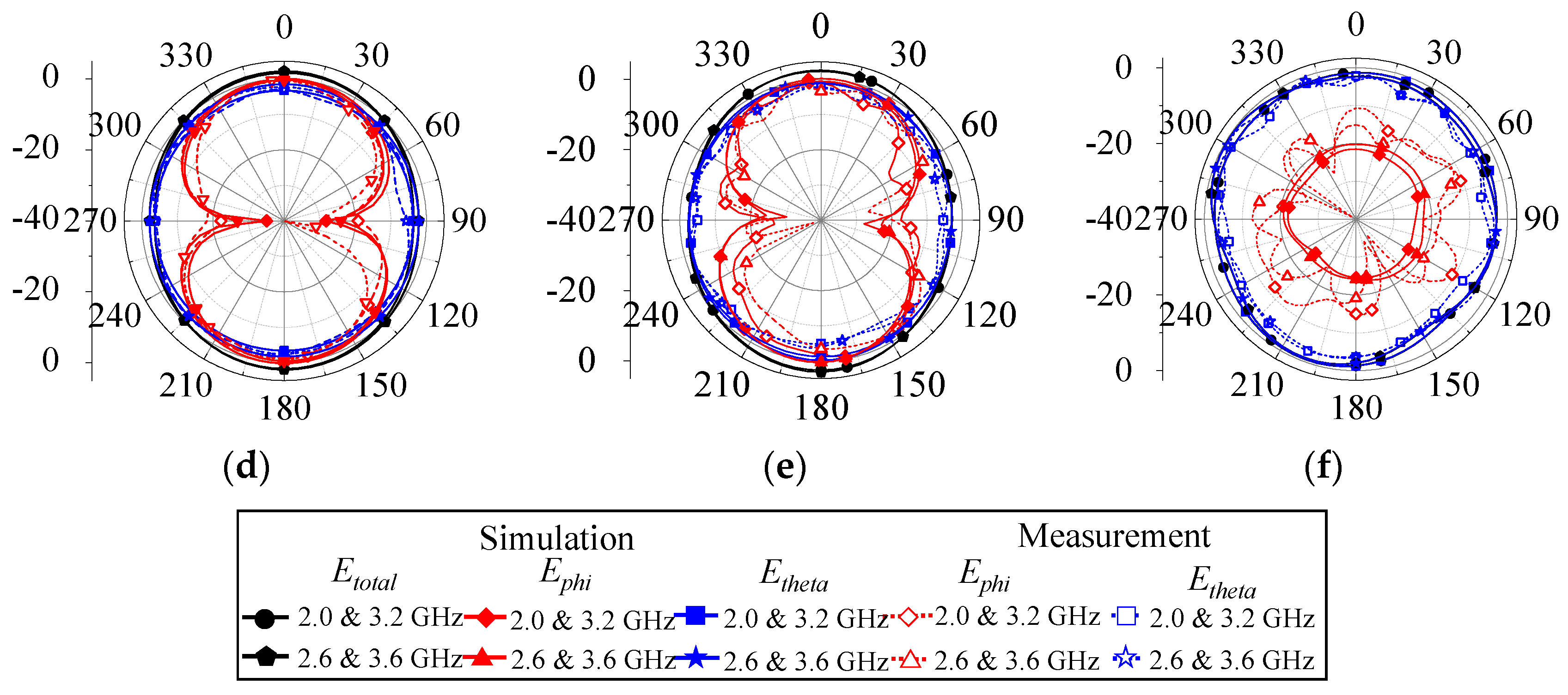
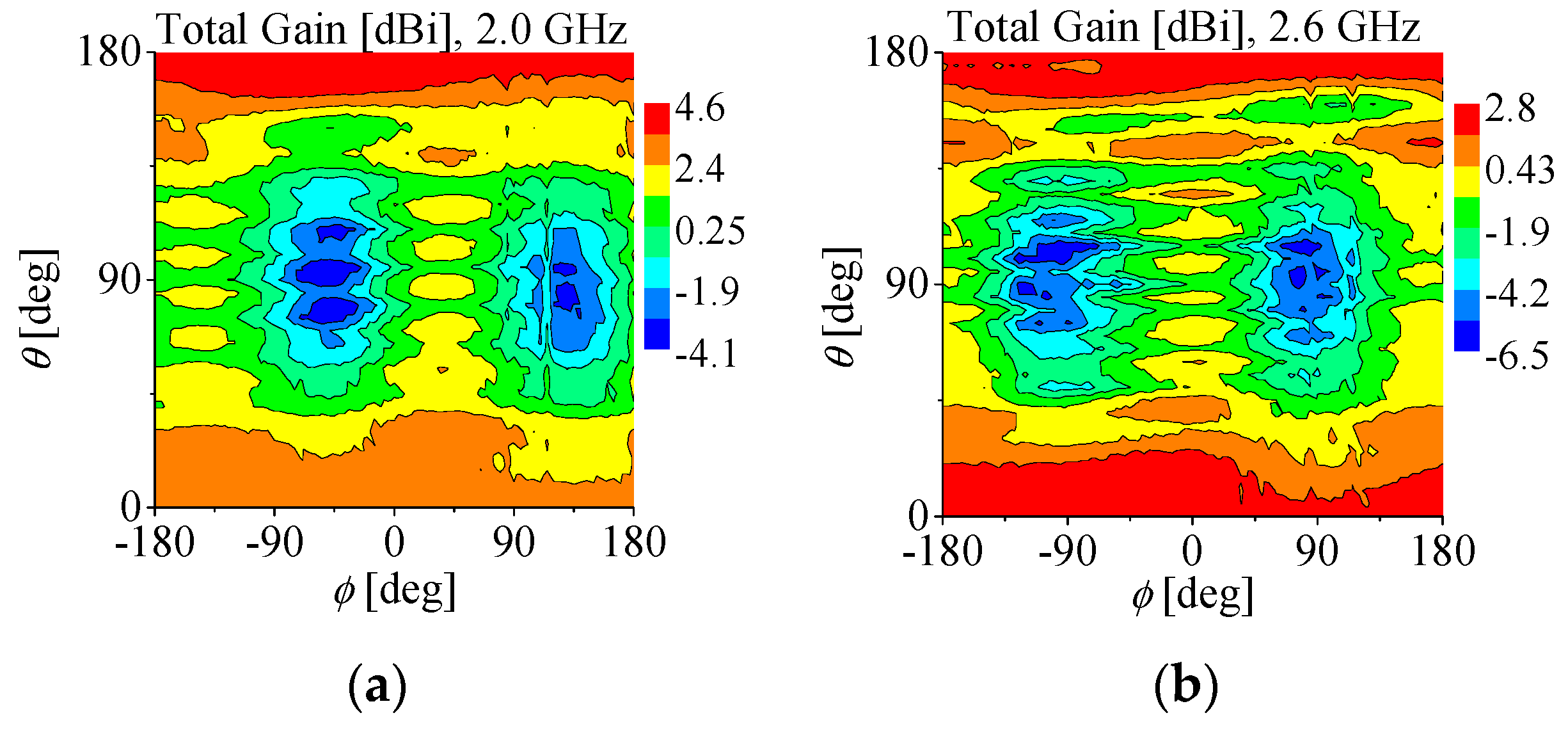
3.1. Radiation Pattern
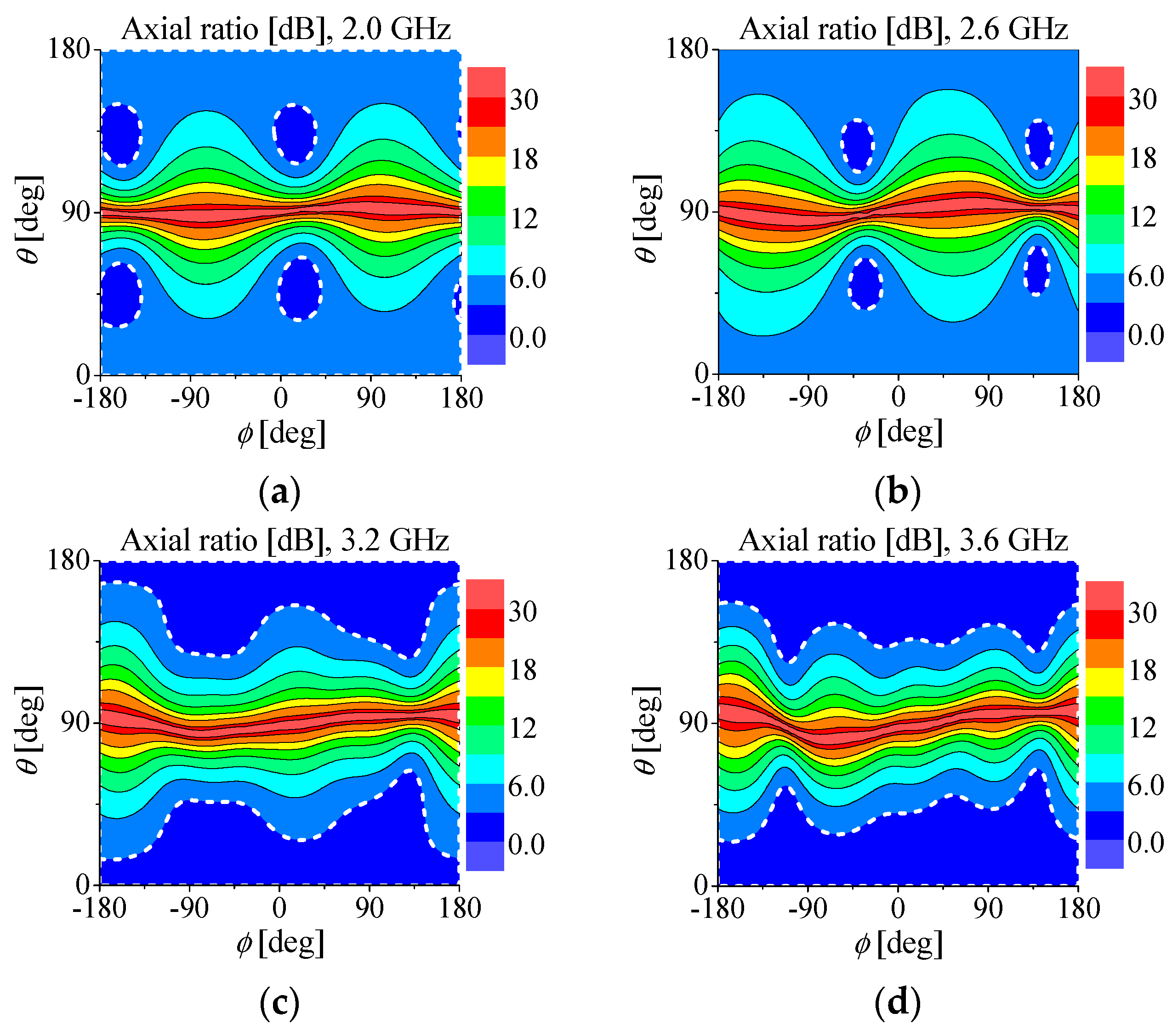
The simulated results of the spherical gain deviation of the proposed antenna are plotted in Figure 8. For brevity, the representative radiation patterns at the four different frequencies of 2.0, 2.6, 3.2, and 3.6 GHz are presented. The maximum gain deviations are 6.3, 8.5, 7.5, and 9.2 dB for the entire space at each frequency. From a practical perspective, obtaining the measured performance expected from the simulation is challenging due to the unbalanced conditions that can occur from the vertical current distribution of the feeding coaxial cable. Therefore, to check the impact of the ferrite beads surrounding the coaxial cable, we carried out a simulation for three different types: one with the ideal port excitation, one with the coaxial cable without the ferrite beads, and one with the coaxial cable covered by the ferrite beads.
The gain deviation performance results from the various excitation methods are plotted in Figure 9. First, we can see that the ideal port without the coaxial cable shows the broadest operating frequencies. The case of the feeding cable with ferrite beads shows a narrower bandwidth than that of the ideal case. Nevertheless, it still shows the comparable bandwidth closest to the ideal port case with a 10 dB gain deviation criterion. This implies that the undesirable vertical current component on the coaxial cable is effectively dissipated by the ferrite beads. In this work, we used ferrite beads of part number 2661000301 from Fair-Rite [41].
Lastly, even when the cable is used without ferrite beads, the gain deviation worsens in terms of bandwidth as well as gain deviation. From this, we can see the effect of the vertical current along the outer conductor of the coaxial cable on the gain deviation of the quasi-isotropic antennas. The antenna performance in the built prototype would be sensitive to the feeding cable.

3.2. CP Performance

The axial ratio (AR) is defined as the ratio between the major to the minor axes of the polarization ellipse in the range of 1 ≤ AR ≤ ∞. CP performance is achieved along the xz- or yz-planes in unidirectional crossed dipole antennas [35,36,37,38]. As shown in Figure 10, where the spherical contour of the AR is plotted at 2.0, 2.6, 3.2, and 3.6 GHz within the operating frequency, the polarization is linear with symmetry in the xy-plane and shows CP nearly at the xz-plane at 2.0 and 2.6 GHz, and the spatial coverage where AR is less than 3 dB is wider by 40% and 44.8% at the higher frequencies of 3.2 and 3.6 GHz, respectively. Note that, at even higher frequencies of 3.8 and 4.0 GHz, where the gain deviations are slightly higher than 10 dB at 11.7 and 12.8 dB, the 3 dB coverage is 43.3% and 40.7%, respectively. The AR value of the region with less than 3 dB is highlighted with the dashed line in the figures.
When compared with the quasi-isotropic antenna in [2], which is composed of electric and magnetic dipoles, and where an AR of less than 3 dB is observed only at a few spots, a wider spatial CP coverage is achieved at the proposed antenna. The CP is created when the linear polarized signals in the same strength are in a 90° phase difference. The desired phase difference is obtained from the vacant ring, and not only the two linear signal paths with an original crossed dipole, as shown in Figure 4a, but also several linear signal paths can be added from the forked-shape arms of the proposed design, as shown in Figure 4c. This also explains the wider AR spatial coverages at 3.2 GHz and 3.6 GHz in Figure 10, where more signal paths can be formed on the electrically larger dimension at higher frequencies. The CP performance might be further improved by adjusting the size, number, and angle of the fork-shaped arms. The proposed antenna shows a better CP performance compared with the other quasi-isotropic antenna designs, such as the electric and magnetic dipole combinations [2] and the folded electric dipoles [26]. In [29], the quasi-isotropic antenna for AoP applications provides radiation with a spatial CP coverage performance of 85%, which is wider than that of the proposed antenna. However, such a feature occurs only at a single resonant frequency.

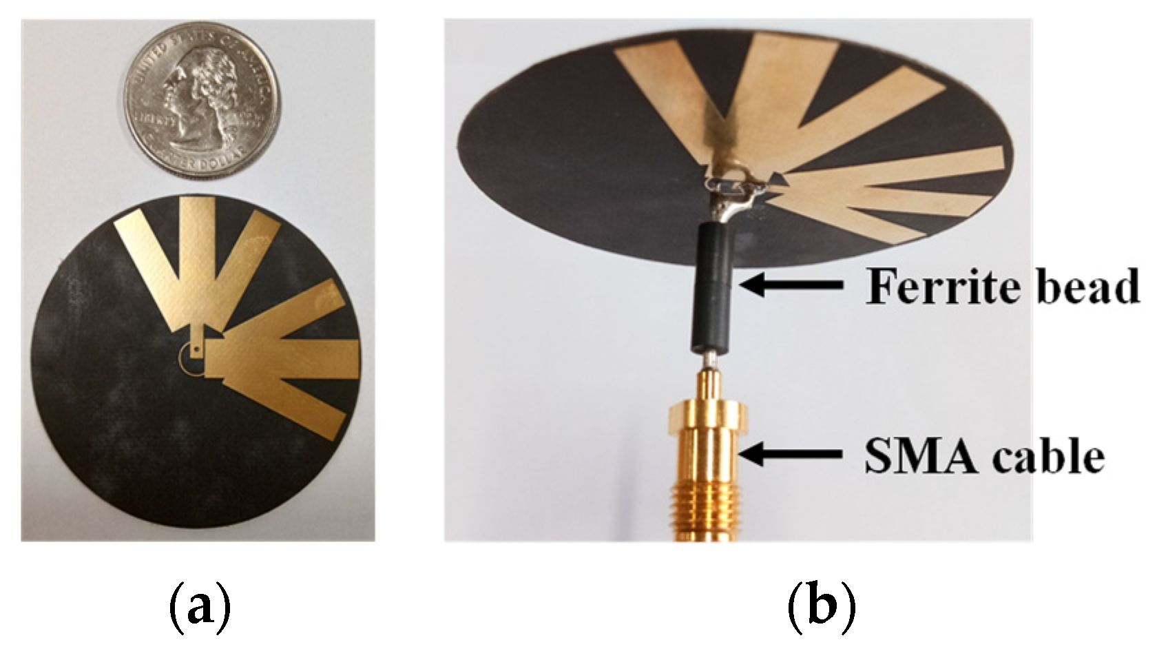
4. Measurements with the Built Prototype

The proposed antenna is built on the same substrate used in the simulation for experimental verification, as shown in the photos in Figure 11. Each metallic arm is etched at the top and bottom sides of the substrate. The proposed antenna is fed using a coaxial cable surrounded by ferrite beads, also used in the simulation, to eliminate the current flows in the outer conductor of the cable. A quarter dollar coin is placed next to the antenna as a size reference in Figure 11a. The measured reflection coefficient can be found in Figure 7, where one can see a good agreement with the simulation.
The radiation performance of the proposed antenna was measured in an anechoic chamber. The elevation (xz-plane) and azimuth (yz- and xy-planes) radiation patterns of the simulated and measured results are presented in Figure 12. Only the radiation patterns at 2.0, 2.6, 3.2, and 3.6 GHz are shown for the brevity of the paper. From this, it can be clearly seen that the proposed antenna shows an omni-directional radiation pattern at the xz- and yz-planes with a good quasi-isotropic radiation pattern at the xy-plane for the observed broad range of frequencies. The simulated and measured results generally agree with each other.
The spherical radiation pattern measurement results are plotted in Figure 13. They show a similar trend to the computed ones, as displayed in Figure 8, although there is a deviation in the absolute gain values. The measured gain deviations across the frequencies can be found in Figure 7. The proposed quasi-isotropic antenna shows a maximum gain deviation in the range of 8.4 to 11.2 dB for the frequency range of 1.9 to 3.5 GHz from the measurement. When compared with the simulated gain deviation, which is in the range of 6.2 to 9.2 dB, the measured gain deviation is a bit higher around 2 dB and is in the range of 8.4 to 9.8 dB at frequencies from 1.9 to 3.3 GHz, where a gain deviation of less than 10 dB is observed. In addition, for frequencies around 1.8, 3.4, and 3.5 GHz, the gain deviations are 12.6, 11.2, and 10.7 dB, respectively. As expected from the simulation results of the different feeding methods shown in Figure 9, the feeding cable will surely affect the measured radiation performance of the antenna. Even though the material properties of the ferrite beads were characterized in the simulation setup, they could vary from those of real products. Another possible reason for the deviation might be from the anechoic chamber measurement setups, including the dielectric supporters, and not perfectly shielded measuring cables. Not only in this design, but also in most cases, quasi-isotropic antennas are quite sensitive to their feeding cables [18,20,25,26]. Even though the measured gain deviation is higher than the simulation results, it is still within the acceptable range of the 10 dB criterion over the broadband frequencies. As illustrated in Figure 14, the measured peak gain is mostly in the range from 2 to 3 dBi, and the efficiency is around 90% from 1.9 to 3.3 GHz.
To verify the CP performance of the proposed antenna, the measured ARs are also plotted for the frequencies of 2.0, 2.6, 3.2, and 3.6 GHz within the target band, as can be seen in Figure 15. The measured ARs of 26.8% and 28.8% with less than 3 dB of coverage are shown at 3.2 and 3.6 GHz, respectively, and they are smaller than the computed expectations shown in Figure 10. This difference might be caused by the sensitive nature of the unshielded feeding cable of the chamber during the measurement. Nevertheless, the linear polarization characteristic along the azimuth plane and the overall tendency of the CP coverage are well verified.
To highlight the novelty and the merits of the proposed antenna design, the electrical size ka and the radiation performance, including the operating bandwidth, gain deviation, and polarization, are compared with those in the previously reported works on quasi-isotropic antennas in Table 2. All of the listed values in the table are from the measurements. While the values in most of the works [23,24], including refs. [26,27], are not electrically small with a ka value larger than 1, the proposed antenna has a ka value of 0.94 with an extremely thin profile of 0.0015λ. It also shows the broadest impedance bandwidth while providing the desired quasi-isotropic radiation characteristic within most of the matched frequencies. Compared with [24,25], the gain deviation is a bit higher, but still within the acceptable range of less than 10 dB, with a much broader operating bandwidth. The antenna in [23] has an electrically smaller size but shows a narrower bandwidth than that of the proposed antenna. Not much information about antenna radiation performance is given for this work. The proposed antenna shows broader and better gain deviation properties than the antenna designs in [26,27] with a simple and compact structure. Among the several designs of quasi-isotropic antennas, refs. [26,30] show the CP performance at narrowband frequencies. In [42], the elliptical loop-based quasi-isotropic antenna shows a broader bandwidth than that of the proposed antenna due to its larger size. Overall, the proposed antenna is highly efficient and shows a broader impedance and CP bandwidth than those in [26,30] with a quasi-isotropic radiation pattern.

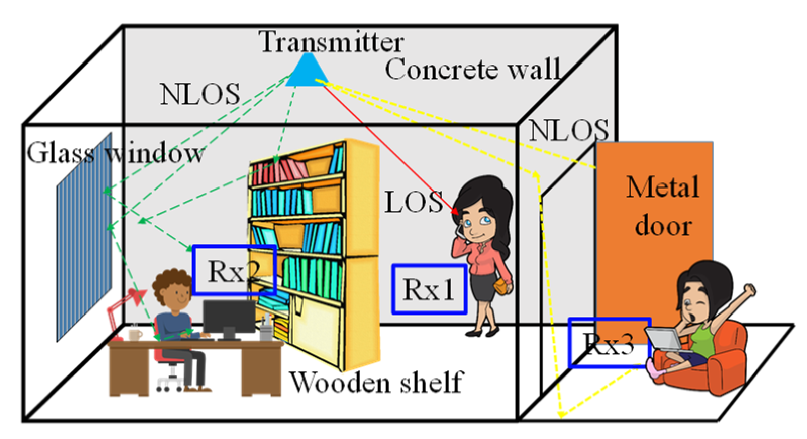
5. Antenna Performance Verification under an NLOS Environment

The quasi-isotropic antenna can be strategically used to provide reliable and robust communications under the NLOS environment [2,17,22]. In this section, we verify the performance of the proposed broadband quasi-isotropic antenna by comparing the received power under line-of-sight (LOS) and NLOS measurement scenarios at the university building corridor. The overall Rx power measurement setup is shown in Figure 16. Two different pairs were set for the measurement. One pair consisted of commercial broadband omni-directional monopole antennas being placed as both Tx and Rx antennas [43]. The monopole antenna was vertically polarized with a length and width of 275 and 45 mm, respectively. The received power values from this setup were used as references. The other consisted of the Rx antenna being replaced with the proposed antenna as a means of verifying the broadband quasi-isotropic performance. The Tx signal was fed from a signal generator, Anritsu MG3692C (Anritsu, Kanagawa, Japan), and amplified by a ZX345 power amplifier (Doggett, Houston, TX, USA) from mini circuits [44]. The Rx antenna was connected to the signal analyzer, Anritsu MS2830A, to measure the amount of received power.
The measurement was performed by moving the position of the Rx antenna from position 0 to position 7, as illustrated in Figure 16. As shown in Figure 17, a concrete wall was used as a block to create the NLOS circumstance between the Tx and Rx antennas. In this measurement, the distance (d) between the Tx and Rx was set as 2 m when the Rx antenna was at position 0. The input power was set at 15 dBm. In all measurements, the position of the Tx antenna was fixed, and only the Rx antenna position was varied from LOS to NLOS.
The measured results are plotted for LOS (at positions 0 and 1) and NLOS (at the other positions) for both pairs of antennas in Figure 18. The results for the case of frequencies of 2.0 and 2.5 GHz are plotted in Figure 18a, and those for the case of frequencies of 3.0 and 3.5 GHz are plotted in Figure 18b.
In the measurement results, the solid lines represent the omni-directional antenna (Tx) and the proposed quasi-isotropic antenna (Rx) pair, whereas the dotted line represents the reference with the omni-directional antenna pair. For positions 0 to 1, the received power shows little difference for both pairs. For positions 2 to 7, however, the received antenna power is clearly higher when the proposed quasi-isotropic antenna is used. There are some points where the proposed antenna shows slightly less power than the omni-directional antenna pair, and this is because the peak gain of the proposed antenna is lower than that of the omni-directional antenna at some frequencies, as in Table 3. Although the overall performance verifies, the quasi-isotropic antenna generally receives better results than the omni-directional antennas. This is due to the merit of the field uniformness in quasi-isotropic antennas that have the capability of receiving more power irrespective of their position.

6. Conclusions

In this paper, a single-feed broadband quasi-isotropic antenna with CP characteristics was proposed. The proposed antenna is compact in terms of its electrical size ka of 0.94 with an extremely low profile of 0.0015λ. It shows a broadband matched impedance bandwidth of 80% from 1.8 to 4.2 GHz with a maximum radiation efficiency of 90%. The maximum gain deviation of less than 10 dB is achieved from 1.9 to 3.3 GHz, or 53.8%, and it is the widest bandwidth considering the small size of the antenna. The wide spatial coverage of the CP performance was also verified experimentally. Furthermore, the performance of the proposed antenna was verified under the NLOS communication environment, showing that a higher level of received power can be obtained by utilizing quasi-isotropic patterns. While the operating frequencies with the quasi-isotropic radiation pattern nearly match the impedance bandwidth, the frequencies for a relatively large coverage of the CP greater than 40% occur only at higher frequencies. A more improved design that simultaneously meets the quasi-isotropic pattern and CP characteristic in a broad bandwidth remains an achievable goal in the near future. The parametric study results given in this work and on the other parameters, such as the number and length of the fingers, are worth revisiting in this regard.

Author Contributions

Conceptualization, S.M.R., M.-S.L. and I.-J.Y.; Methodology, S.M.R., M.-S.L. and I.-J.Y.; Software, S.M.R., M.-S.L. and I.-J.Y.; Validation, S.M.R., M.-S.L. and I.-J.Y.; Formal Analysis, S.M.R., M.-S.L. and I.-J.Y.; Investigation, S.M.R., M.-S.L. and I.-J.Y.; Resources, S.M.R., M.-S.L. and I.-J.Y.; Data Curation, S.M.R., M.-S.L., S.H.C. and I.-J.Y.; Writing—Original Draft Preparation, S.M.R.; Writing—Review and Editing, I.-J.Y.; Visualization, S.M.R. and S.H.C.; Supervision, I.-J.Y. All authors have read and agreed to the published version of the manuscript.

Funding

This work was supported by Chungnam National University.

Institutional Review Board Statement

Not applicable.

Informed Consent Statement

Not applicable.

Data Availability Statement

The original contributions presented in the study are included in the article, further inquiries can be directed to the corresponding author.

Conflicts of Interest

The authors declare no conflicts of interest.

References

  1. Park, P.; Ergen, S.C.; Fischione, C.; Lu, C.; Johansson, K.H. Wireless network design for control systems: A survey. IEEE Commun. Surv. Tuts. 2018, 20, 978–1013. [Google Scholar] [CrossRef]
  2. Radha, S.M.; Jung, M.; Park, P.; Yoon, I.-J. Design of an electrically small, planar quasi-isotropic antenna for enhancement of wireless link reliability under NLOS channels. Appl. Sci. 2020, 10, 6204. [Google Scholar] [CrossRef]
  3. Luvisotto, M.; Pang, Z.; Dzung, D. High-performance wireless networks for industrial control applications: New targets and feasibility. Proc. IEEE 2019, 107, 1074–1093. [Google Scholar] [CrossRef]
  4. Lin, W.; Ziolkowski, R.W. Wirelessly powered light and temperature sensors facilitated by electrically small omni-directional and Huygens dipole antennas. Sensors 2019, 19, 1998. [Google Scholar] [CrossRef]
  5. Ta, S.X.; Choo, H.; Park, I.; Ziolkowski, R.W. Multi-band, wide-beam, circularly polarized, cross, asymmetrically barbed dipole antennas for GPS applications. IEEE Trans. Antennas Propag. 2013, 61, 5771–5775. [Google Scholar] [CrossRef]
  6. Park, P. Markov chain model of fault-tolerant wireless networked control systems. Wirel. Netw. 2018, 25, 2291–2303. [Google Scholar] [CrossRef]
  7. Baik, J.W.; Lee, T.H.; Pyo, S.; Han, S.M.; Jeong, J.; Kim, Y.S. Broadband circularly crossed dipole with parasitic loop resonators and its array. IEEE Trans. Antennas Propag. 2011, 59, 80–88. [Google Scholar] [CrossRef]
  8. Youn, S.; Jang, B.; Choo, H. Design of a UWB antenna with multiple ports on a single circular radiator for directing-finding applications. J. Electromagn. Eng. Sci. 2023, 23, 63–68. [Google Scholar] [CrossRef]
  9. Wang, X.; Zhao, Z.; Chen, G.; He, F. RF energy harvesting with broadband antenna. In Proceedings of the 2014 IEEE Conference and Expo Transportation Electrification Asia-Pacific (ITEC Asia-Pacific), Beijing, China, 31 August–3 September 2014; pp. 1–5. [Google Scholar]
  10. Maher, R.; Tammam, E.; Galal, I.; Hamed, H.F. Design of a broadband planar antenna for RF energy harvesting. In Proceedings of the International Conference on Electrical, Electronics, and Optimization Techniques (ICEEOT), Chennai, India, 3–5 March 2016; pp. 1808–1810. [Google Scholar]
  11. Hagerty, J.A.; Helmbrecht, F.B.; McCalpin, W.H.; Zane, R.; Popovic, Z.B. Recycling ambient microwave energy with broad-band rectenna arrays. IEEE Trans. Microw. Theory Tech. 2004, 52, 1014–1024. [Google Scholar] [CrossRef]
  12. Long, H.; Liu, Y.; Wang, Y.; Dick, R.P.; Yang, H. Battery allocation for wireless sensor network lifetime maximization under cost constraints. In Proceedings of the IEEE/ACM International Conference on Computer-Aided Design-Digest of Technical Papers, San Jose, CA, USA, 2–5 November 2009; pp. 705–712. [Google Scholar]
  13. Mathis, H.F. A short proof that an isotropic antenna is impossible. Proc. IRE 1951, 8, 970. [Google Scholar]
  14. Brouwer, L.E.J. On Continuous Vector Distributions on Surfaces; Proc. KNAW: Amsterdam, The Netherlands, 1909; Volume 11, pp. 850–858. [Google Scholar]
  15. Bugnolo, D. A quasi-isotropic antenna in the microwave spectrum. IRE Trans. Antennas Propag. 1962, 10, 377–383. [Google Scholar] [CrossRef]
  16. Radha, S.M.; Shin, G.; Park, P.; Yoon, I.-J. Realization of electrically small, low-profile quasi-isotropic antenna using 3D printing technology. IEEE Access 2020, 8, 27067–27073. [Google Scholar] [CrossRef]
  17. Bou-El-Harmel, A.; Benbassou, A.; Belkadid, J.; Mechatte, N. Effect of quasi-isotropic antenna orientation on indoor multipath propagation characteristics in RSN applications. Int. J. Antennas Propag. 2017, 2017, 2686123. [Google Scholar] [CrossRef]
  18. Pan, G.; Li, Y.; Zhang, Z.; Feng, Z. Isotropic radiation from a compact planar antenna using two crossed dipoles. IEEE Antennas Wirel. Propag. Lett. 2012, 11, 1338–1341. [Google Scholar]
  19. Kim, J.; Park, J.; Omar, A.A.; Hong, W. A symmetrically stacked planar antenna concept exhibiting quasi-isotropic radiation coverage. IEEE Antennas Wirel. Propag. Lett. 2020, 19, 1390–1394. [Google Scholar] [CrossRef]
  20. Kim, J.-H.; Nam, S. Design of a compact dual band quasi-isotropic antenna. Electron. Lett. 2017, 53, 515–516. [Google Scholar] [CrossRef]
  21. Su, Z.; Klionovski, K.; Bilal, R.M.; Shamim, A. A dual band additively manufactured 3-D antenna on package with near-isotropic radiation pattern. IEEE Trans. Antennas Propag. 2018, 66, 3295–3305. [Google Scholar] [CrossRef]
  22. Radha, S.M.; Shin, G.; Kim, W.; Shah, S.I.H.; Yoon, I.-J. Design and verification of an electrically small, extremely thin dual-band quasi-isotropic antenna. IEEE Antennas Wirel. Propag. Lett. 2020, 19, 2482–2486. [Google Scholar] [CrossRef]
  23. Tang, Z.-J.; He, Y.-G.; Wang, Y. Broadband UHF RFID tag antenna with quasi-isotropic radiation performance. Int. J. Electron. Commun. 2011, 65, 859–863. [Google Scholar] [CrossRef]
  24. Cho, C.; Choo, H.; Park, I. Broadband RFID tag antenna with quasi-isotropic radiation pattern. Electron. Lett. 2005, 41, 1091–1092. [Google Scholar] [CrossRef]
  25. Deng, C.; Li, Y.; Zhang, Z.; Feng, Z. A wideband isotropic radiated planar antenna using sequential rotated L-shaped mon-opoles. IEEE Trans. Antennas Propag. 2014, 62, 1461–1464. [Google Scholar] [CrossRef]
  26. Su, Z.; Klionovski, K.; Liao, H.; Chen, Y.; Elsherbeni, A.Z.; Shamim, A. Antenna-on-package design: Achieving near-isotropic radiation pattern and wide CP coverage simultaneously. IEEE Trans. Antennas Propag. 2021, 69, 3740–3749. [Google Scholar] [CrossRef]
  27. Pazin, L.; Dyskin, A.; Leviatan, Y. Quasi-isotropic X-band inverted-F antenna for active RFID tags. IEEE Antennas Wirel. Propag. Lett. 2009, 8, 27–29. [Google Scholar] [CrossRef]
  28. Shah, S.I.H.; Radha, S.M.; Park, P.; Yoon, I.-J. Recent advancements in quasi-isotropic antennas: A review. IEEE Access 2021, 9, 146296–146317. [Google Scholar] [CrossRef]
  29. Su, Z.; Klionovski, K.; Liao, H.; Li, W.; Shamim, A. A fully-printed 3D antenna with 92% quasi-isotropic and 85% CP coverage. IEEE Trans. Antennas Propag. 2022, 70, 7914–7922. [Google Scholar] [CrossRef]
  30. Huchard, M.; Delaveaud, C.; Tedjini, S. Miniature antenna for circularly polarized quasi isotropic coverage. In Proceedings of the 2nd European Conference on Antennas and Propagation (EuCAP 2007), Edinburgh, UK, 11–16 November 2007; pp. 1–5. [Google Scholar]
  31. Wu, D.L. Omnidirectional circularly-polarized conformal microstrip array for telemetry applications. IEEE Antennas Propag. Soc. Int. Symp. 1995, 2, 998–1001. [Google Scholar]
  32. Hall, R.C.; Wu, D.I. Modeling and design of circularly-polarized cylindrical wraparound microstrip antennas. In Proceedings of the International Symposium Antennas Propagation, Baltimore, MD, USA, 21–26 July 1996; pp. 672–675. [Google Scholar]
  33. Ta, S.X.; Park, I.; Ziolkowski, R.W. Crossed dipole antennas: A review. IEEE Antennas Propag. Mag. 2015, 57, 107–122. [Google Scholar] [CrossRef]
  34. Radha, S.M.; Lee, M.-S.; Yoon, I.-J. A Compact broadband quasi-isotropic antenna for wireless energy harvesting applications. In Proceedings of the 2022 International Symposium on Antennas and Propagation (ISAP), Sydney, Australia, 31 October–3 November 2022; pp. 137–138. [Google Scholar]
  35. Ta, S.X.; Park, I. Compact wideband sequential-phase feed for sequentially rotated antenna arrays. IEEE Antennas Wirel. Propag. Lett. 2017, 16, 661–664. [Google Scholar] [CrossRef]
  36. Bolster, M.F. A new type of circular polarizer using crossed dipoles. IRE Trans. Microw. Theory Tech. 1961, 9, 385–388. [Google Scholar] [CrossRef]
  37. Ta, S.X.; Park, I.; Ziolkowski, R.W. Broadband electrically small circularly polarized directive antenna. IEEE Access 2017, 5, 14657–14663. [Google Scholar] [CrossRef]
  38. Shin, H.W.; Kim, H.D. Enhancing efficiency for wideband antennas by controlling the parasitic resonance of the feed structure. J. Electromagn. Eng. Sci. 2021, 22, 399–402. [Google Scholar] [CrossRef]
  39. Huynh, M.-C. Wideband Compact Antenna for Wireless Communications Applications. Ph.D. Dissertation, Virginia Polytechnic Institute and State University, Blacksburg, VA, USA, 2004. [Google Scholar]
  40. Farooqui, M.F.; Claudel, C.; Shamim, A. An inkjet-printed buoyant 3-D lagrangian sensor for real-time flood monitoring. IEEE Trans. Antennas Propag. 2014, 62, 3354–3359. [Google Scholar] [CrossRef]
  41. Ferrite Beads: 2661000301. Available online: https://www.fair-rite.com/product/emi-suppression-beads-2661000301/ (accessed on 5 January 2024).
  42. Arrawatia, M.; Baghini, M.S.; Kumar, G. Broadband modified elliptical ring quasi-isotropic antenna. In Proceedings of the IEEE International Symposium on Antennas and Propagation & USNC/URSI, Boston, MA, USA, 8–13 July 2018; pp. 1055–1056. [Google Scholar]
  43. Ultra Wide Band Omni Directional Antenna. Available online: http://antenna-pro.com/product/detail.html?product_no=2073&cate_no=166&display_group=1 (accessed on 5 January 2024).
  44. High Power Amplifier: ZHL-2W-63x-S+. Available online: https://www.minicircuits.com/WebStore/dashboard.html?model=ZHL-2W-63X-S%2B (accessed on 5 January 2024).
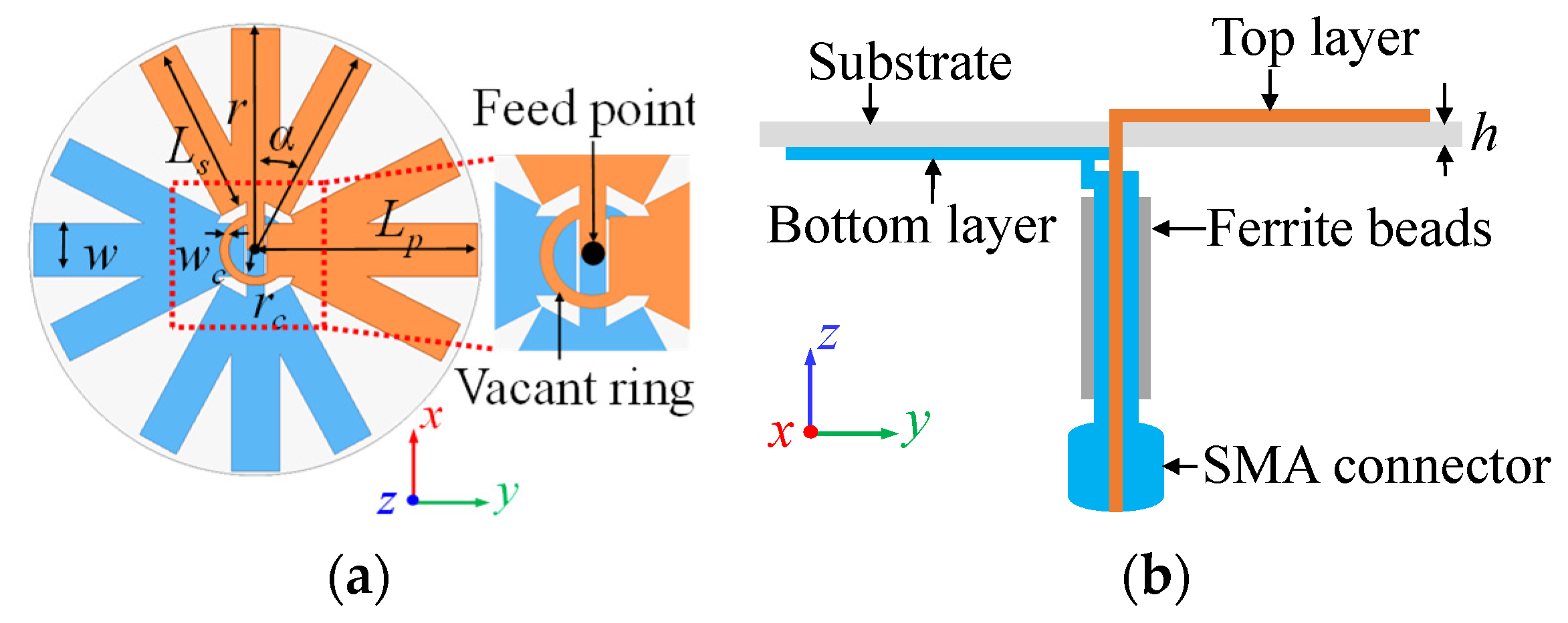
Figure 1. Representation of the NLOS environment.
Applsci 14 02068 g001
Figure 2. Basic configuration of the crossed dipole antenna. (a) x-oriented dipole and its radiation pattern. (b) y-oriented dipole and its radiation pattern.
Applsci 14 02068 g002
Figure 3. Configuration of the proposed fork-shaped crossed dipole antenna. (a) Top view. (b) Side view.
Applsci 14 02068 g003
Figure 4. Development of the proposed antenna design and its current distribution at 2.4 GHz. (a) Original crossed dipole antenna (Antenna I). (b) Tapered-shaped crossed dipole antenna (Antenna II). (c) Proposed fork-shaped crossed dipole antenna.
Applsci 14 02068 g004
Figure 5. Simulation results of the performance of the crossed dipole antennas in the design stage shown in Figure 4. (a) Reflection coefficient. (b) Gain deviation.
Applsci 14 02068 g005
Figure 6. Parameter study results. (a) Effects of rc. (b) Effects of h. (c) Effects of α.
Applsci 14 02068 g006
Figure 7. Reflection coefficient and gain deviation of the final design.
Applsci 14 02068 g007
Figure 8. Simulated spherical gain deviations of the proposed antenna: (a) 2.0 GHz, (b) 2.6 GHz, (c) 3.2 GHz, and (d) 3.6 GHz.
Applsci 14 02068 g008
Figure 9. Simulated gain deviation of the proposed antenna with respect to excitation methods.
Applsci 14 02068 g009
Figure 10. Simulation results of CP performance: (a) 2.0 GHz, (b) 2.6 GHz, (c) 3.2 GHz, and (d) 3.6 GHz.
Applsci 14 02068 g010
Figure 11. Photos of the built antenna. (a) Top view. (b) Bird’s eye view.
Applsci 14 02068 g011
Figure 12. Simulated and measured radiation patterns: (a) xz-plane at 2.0 and 2.6 GHz, (b) yz-plane at 2.0 and 2.6 GHz, (c) xy-plane at 2.0 and 2.6 GHz, (d) xz-plane at 3.2 and 3.6 GHz, (e) yz-plane at 3.2 and 3.6 GHz, and (f) xy-plane at 3.2 and 3.6 GHz.
Applsci 14 02068 g012aApplsci 14 02068 g012b
Figure 13. Measured spherical gain deviations of the proposed antenna: (a) 2.0 GHz, (b) 2.6 GHz, (c) 3.2 GHz, and (d) 3.6 GHz.
Applsci 14 02068 g013aApplsci 14 02068 g013b
Figure 14. Simulated and measured peak gain and efficiency.
Applsci 14 02068 g014
Figure 15. Measurement results of CP performance: (a) 2.0 GHz, (b) 2.6 GHz, (c) 3.2 GHz, and (d) 3.6 GHz.
Applsci 14 02068 g015aApplsci 14 02068 g015b
Figure 16. Received power measurement setup.
Applsci 14 02068 g016
Figure 17. Experiment setup at the university building corridor. (a) LOS. (b) NLOS.
Applsci 14 02068 g017
Figure 18. Measurement results of received power for the different operating frequencies: (a) 2.0 and 2.5 GHz and (b) 3.0 and 3.5 GHz.
Applsci 14 02068 g018
Table 1. Antenna design parameters.
ParametersDescriptionValue
LpLength of the primary dipole24.5
LsFork-shaped arm length22
WWidth of the dipole 1.5
αAngle between the dipoles11
wcWidth of the vacant ring0.25
rcRadius of the vacant ring2.5
rRadius of the substrate25
hThickness of the substrate0.254
Note: All of the values are in millimeters except for α, which is in degrees.
Table 2. Performance comparison of the proposed broadband quasi-isotropic antenna with other reported quasi-isotropic antennas.
Ref.Design MethodDimension
[mm]
kaMatched Frequency
[GHz]
Fractional Bandwidth
[%]
Pattern Bandwidth
[GHz]
Gain Deviation
[dB]
CP Eff.
[%]
[16]Electric dipole and loop antenna25 (Radius) × 2.2 (H)0.480.952.4N/A4.5No81
[23]Meandered dipole98.7 (L) × 14.2 (W) × 0.05 (H)0.90.84–0.9520N/AN/ANoN/A
[24]Twisted dipole
with matching network
79.2 (L) × 53.1 (W) × 0.05 (H)1.60.84–0.928.50.88–0.966NoN/A
[25]L-shaped monopole with feeding network45 (L) × 45 (W) × 0.8 (H)1.462.2–2.720.82.36–2.536No80
[26]Electric dipole along x, y, and z-axes95 (L) × 95 (W) × 95 (H)1.21.31–1.81321.512.52YesN/A
[27]Inverted-F antenna52 (L) × 37 (W) × 1.6 (H)7.0110.515N/A10.5NoN/A
[30]Inverted-F antenna25 (L) × 25 (W) × 3.1 (H)0.882.44.1N/A3.6Yes65
[42]Elliptical loop100 (L) × 90 (W) × 1.59 (H)1.150.82–3.5124N/AN/ANoN/A
This workCrossed dipole25 (Radius) × 0.254 (H)0.941.8–4.2801.9–3.38.4~9.8Yes90
Table 3. Antennas used for demonstration.
Frequency [GHz]Peak Gain [dBi]
Omnidirectional antennaLength of the primary dipole24.5
Proposed antenna1.8~4.21.6~4
Disclaimer/Publisher’s Note: The statements, opinions and data contained in all publications are solely those of the individual author(s) and contributor(s) and not of MDPI and/or the editor(s). MDPI and/or the editor(s) disclaim responsibility for any injury to people or property resulting from any ideas, methods, instructions or products referred to in the content.

