Article

MRAS Using Lyapunov Theory with Sliding Modes for a Fixed-Wing MAV

1
Faculty of Engineering, Sciences and Architecture, Juarez University of the State of Durango, Gómez Palacio 35070, Durango, Mexico
2
Faculty of Automatic Control, Robotics and Electrical Engineering, Institute of Robotics and Machine Intelligence, Poznan University of Technology, ul. Piotrowo 3a, 60-965 Poznan, Poland
*
Author to whom correspondence should be addressed.
Appl. Sci. 2024, 14(5), 2198; https://doi.org/10.3390/app14052198
Submission received: 29 January 2024 / Revised: 27 February 2024 / Accepted: 27 February 2024 / Published: 6 March 2024
(This article belongs to the Special Issue Aerial Robotics and Vehicles: Control and Mechanical Design)

Abstract

:
This work applies an adaptive PD controller based on MRAS (Model Reference Adaptive System) using Lyapunov theory with sliding mode theory to a Fixed-wing MAV (Mini Aerial Vehicle). The objective is to design different adjustment mechanisms to obtain a robust adaptive control law in the presence of unknown perturbation due to wind gusts. Four adjustment mechanisms applied to an adaptive PD controller are compared. The adjustment mechanisms are Lyapunov theory, Lyapunov theory with first-order sliding mode, Lyapunov theory with second-order sliding mode, and Lyapunov theory with high-order sliding mode. Finally, after several simulations, a significant reduction and almost elimination of the unknown perturbations are presented with the addition of the sliding mode theory in the design of the adjustment mechanism for the adaptive PD controller.

1. Introduction

The fixed-wing MAVs are used for civil and military applications, and a vast array of research fields in this type of aerial machines like mathematics modeling, aerodynamic design, avionics, control theory, state observers, materials design for UAVs, and other less critical research or studies of external disturbances. External disturbances are a significant natural external force over the UAVs that should be studied because every unmanned aerial vehicle (UAV) has a problem when flying in the presence of perturbations (wind gusts, wind shear, and turbulence). Then, it is not easy to achieve a stable flight or the desired performance for any unmanned aerial vehicle when the perturbations are unknown.
Other authors have studied adaptive control theory to propose solutions to achieve a stable flight with fixed-wing UAVs; for example, in [1], an adaptive controller based on fuzzy logic and sliding mode control (SMC) is designed, ref. [1] used fuzzy logic to reduce the chattering in the SMC and used the SMC methodology to approximate the uncertain parameters and unknown functions caused by the external perturbations or disturbances. Two types of fuzzy adaptive SMC for different fuzzy ranges are proposed.
An extended observer based on adaptive second-order SMC is presented in [2] to control attitude in a smoothly feasible route of a fixed-wing UAV. The general idea in [2] is to use the observer to estimate the unknown disturbance and bound to obtain the system stability.
On the other hand, in [3], the adaptive sliding mode control is applied to the carrier landing of fixed-wing UAVs. The results are obtained via simulations to appreciate the control effectiveness; the objective of the adaptive controller in [3] is to track the desired landing path and consider a simplification of the aerodynamic model from six degrees of freedom (6-DOF) to four degrees of freedom (4-DOF) and considering the pitch and roll angles constant.
In [4], an automatic tuning approach for fixed-wing UAVs is presented to obtain the controller parameters. First, specific gains and phase margins are computed or calculated. A wind tunnel is even used to validate the closed-loop response with the proposed methodology.
In [5], a robust gain-schedule autopilot for a guided projectile is presented; the gain schedule is based on H-infinity baseline autopilots and proposed and evaluated as an anti-windup compensator.
The gain scheduling is used to tune the gains for a proportional-integral-derivative PID applied for the attitude in a fixed-wing UAV [6]. It is subject to several operating conditions of airspeed. An automatic tuning algorithm carries it out, and it should be mentioned that it uses a family of PID cascade control.
In [7], the simulation results for a model-free adaptive control where the model information for the control scheme design is not necessary to try with the uncertainties is presented, and an attitude control is applied for fixed-wing UAVs. The adaptive backstepping sliding mode is probed by numerical simulations in [8] to stabilize the altitude, attitude, and velocity for a fixed-wing UAV, and even in the controller designed, it is applied with multiple algorithm fusion.
The L 1 adaptive control with linearized model dynamics is used in [9] to realize path-following with a small fixed-wing UAV subject to wind disturbances. The results are presented by numerical simulation, and even the L 1 adaptive control is presented in [10] but considering a full-order nonlinear model of the fixed-wing UAV, and the results are obtained with computer simulations. To stabilize a fixed-wing UAV in attitude and altitude, an adaptive super twisting algorithm is presented in [11], and this controller ensures finite time convergence; computer simulations obtain the results.
Then, this work proposes three adjustment mechanisms based on the Lyapunov theory and sliding mode theory to obtain three robust adjustment mechanisms to auto-tune the proportional and derivative gains for an adaptive PD controller. Due to the fixed-wing UAVs being used in different fields or tasks where it is necessary to fly in other weather conditions, different altitudes and attitudes, and variable speeds, the adaptive controller with the three robust adjustment mechanisms proposed is applied to a fixed-wing MAV to probe the effectiveness and robustness of the adjustment mechanism in the presence of disturbances by unknown wind-gusts. Several computer simulations present the results. The main contributions of this work are:
  • A new design of the adjustment mechanism for an MRAS is obtained based on Lyapunov theory and sliding mode theory, with the control objective to achieve the desired values in attitude and altitude in a fixed-wing MAV despite unknown wind gusts.
  • The significant reduction in the oscillations in the system with the sliding mode theory to the design of the adjustment mechanism.
  • Achieve the control objective in attitude and altitude by designing two adjustment mechanisms for the proportional and derivative gains.
  • The stability proof of the adjustment mechanisms considering the Lyapunov and sliding modes theory and the stability proof of the controller.
On the other side, in future work, the development of specific applications with fixed-wing MAVs like Topography [12,13], photogrammetry [14,15], forest fire detection [16], surveillance or missions inspection [17], for shorelines investigation [18], precision agriculture [19,20] or others, is possible.
This work is organized as follows: Section 2 shows the mathematical model to define the fixed-wing UAV. Section 3 presents the adaptive controller with a robust adjustment design. Section 4 shows the simulation results obtained after several tests. Finally, Section 5 presents the discussion, and the future work.

2. Fixed-Wing MAV Mathematical Model

The complete mathematical model of the fixed-wing MAV considers an inertial fixed frame I = { x I , y I , z I } , and the body frame fixed attached to the center of gravity of the fixed-wing MAV given by B = { x B , y B , z B } .
The W = { x W , y W , z W } represents the wind frame, and it is considered during the cruise of the fixed-wing MAV [21]. In this work, the Newton–Euler formulation is applied to obtain the equations of motion for the fixed-wing MAV and is given by the following mathematical model [22].
ξ ˙ = V
m V ˙ = R F + m g e 3
η ˙ = Φ ( η ) Ω
I Ω ˙ = Ω × I Ω + Γ
with ξ = ( x , y , z ) T R 3 like the position coordinates relative to the inertial frame, the rotation coordinates is given by η = ( ϕ , θ , ψ ) T R 3 . The orientation of the rigid body is represented by an orthogonal rotation matrix R S O ( 3 ) : B I , which can be parameterized by the Euler angles ϕ , θ and ψ which represent the roll, pitch, and yaw, respectively.
The translational velocity in B is defined by ν = ( u , v , w ) T R 3 , and the angular velocity in B is represented with Ω = p , q , r T R 3 , the translational velocity is defined with V = ( x ˙ , y ˙ , z ˙ ) T R 3 in I . The total forces and moments acting on the vehicle F R 3 and Γ R 3 , respectively. The third vector of the canonical basis of R 3 is represented with e 3 in the z- axis, m R is the mass of the fixed-wing MAV, the matrix, which represents or contains the inertial moments is I R 3 × 3 . The Φ ( η ) is the Euler matrix and describes the relation between η and Ω .
Φ ( η ) = 1 sin ϕ tan θ cos ϕ tan θ 0 cos ϕ sin ϕ 0 sin ϕ sec θ cos ϕ sec θ
Finally, the matrix E : B W describes the transformation of a vector from the body frame to the wind frame, and this matrix is essential to develop the aerodynamic analysis. The winding frame is given by
E = c α c β s β s α c β c α s β c β s α s β s α 0 c α
with α is the angle of attack and β is the side slip angle [21].
To design the MRAS using Lyapunov theory with sliding modes, the model of Equations (1)–(4) omitted any flexible structure of the fixed-wing MAV. This is considered a rigid body. Also, the curvature of the earth is not considered because it is assumed that the fixed-wing MAV will only fly short distances. Then, the mathematical model of the pure angle motion in pitch is necessary to achieve the desired altitude.
The same concept of pure motion is considered for the yaw and roll angles. Thus, the objective is to obtain an adaptive controller for the Euler angles of the fixed-wing MAV and achieve the desired altitude and the desired angles despite the unknown perturbations due to the wind gusts. As previously explained, we have uncoupled the mathematical model of the fixed-wing MAV in three aerodynamic models: longitudinal dynamic and directional-lateral dynamic.

2.1. Longitudinal Dynamics

The longitudinal dynamic model to design the adaptive altitude control is given by [23,24,25], is given by:
θ ˙ = q
q ˙ = ρ S V c ¯ 2 4 I y y C m q q + ρ V 2 S c ¯ 2 I y y C m δ e δ e
h ˙ = V sin ( θ )
where θ denotes the pitch angle, and q is the pitch angular rate concerning the y-axis of the fixed-wing MAV. The air density is defined with ρ , and the wing area S. The fixed-wing MAV speed is given by V, and c ¯ is the standard mean chord. The moment of inertia in pitch is I y y . C m q and C m δ e are the dimensionless coefficients for the longitudinal movement, and the values of these constant values are in Table 1. The h defines the fixed-wing MAV altitude, and δ e represents the elevator deflection. These variables are represented in Figure 1.

2.2. Directional-Lateral Dynamic

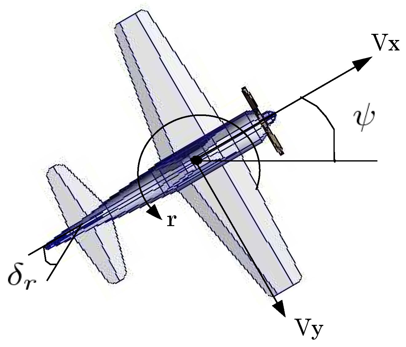
The lateral dynamics generate the roll motion and, simultaneously, induce a yaw motion (and vice versa); then, a natural coupling exists between the rotations about the roll and yaw axes [24]. It is considered a decoupling of the yaw and roll angles [25]. Thus, each angle can be seen as a pure motion and controlled independently. Generally, the effects of the engine thrust are also ignored [24]. In Figure 2, the yaw angle (directional dynamics) is represented, described by the following equations:
ψ ˙ = r
r ˙ = ρ V S b 2 4 I z z C n r r + ρ V 2 S b 2 I z z C n δ r δ r
where ψ represents the yaw angle and r denotes the yaw rate concerning the center of gravity of the fixed-wing MAV. δ r is the rudder deviation. C n r and C n δ r are the dimensionless coefficients for the yaw angle, and the values of these constant values are in Table 1. The equations that define the lateral dynamics or roll angle are:
ϕ ˙ = p
p ˙ = ρ V S b 2 4 I x x C l p p + ρ V 2 S b 2 I x x C l δ a δ a
where p denotes the roll rate, ϕ describes the roll angle, and δ a represents the deflection of the ailerons. C l p and C l δ a are the dimensionless coefficients for the roll angle. The constant values are in Table 1. Figure 3 presents the roll motion variables.
Remark 1.
The mathematical uncoupled model represents the Euler angles and the angular rates because in real-time flight tests it is possible to achieve the desired attitude and altitude of the fixed-wing MAV (see [26,27,28]). To develop the adaptive controller presented in this work requires knowledge of such physical variables. Table 1 contains the parameters essential parameters. The Solid Works (2020) software obtained some of these values, and the aerodynamic coefficients were obtained experimentally.

3. Adaptive Controller Design and Stability Proof

This section describes the adjustment mechanisms of the adaptive proportional gain and the derivative gain designed for a PD controller. These are represented by k ^ p κ a x and k ^ d κ a x , respectively, with κ : = θ , ψ , ϕ and the sub-index x = 1 , 2 , 3 , 4 a x . Thus, a 1 means are used to adjust the adaptive gains via Lyapunov theory, a 2 corresponds, which the Lyapunov theory with sliding mode (L-SM) to adjust the adaptive gains, a 3 corresponds to Lyapunov theory with second-order sliding mode (L-2SM), and a 4 corresponds the Lyapunov theory with high order sliding mode (L-HOSM) to adjust the adaptive gains in the control law.
To design the adjustment mechanism, the continuous-time model reference adaptive system (MRAS) using Lyapunov theory with different sliding-modes techniques is used to obtain a robust mechanism to achieve the control objective; that is, the fixed-wing MAV must stay at a desired altitude and in the desired yaw and roll angles despite the unknown perturbations such perturbations are due to the wind gusts. The MRAS block diagram is presented in Figure 4.
Considering the equations that describe the longitudinal dynamic and directional-lateral dynamic, the adaptive controller is given by:
δ e δ r δ a = k ^ p θ a x 0 0 0 k ^ p ψ a x 0 0 0 k ^ p ϕ a x e θ e ψ e ϕ + k ^ d θ a x 0 0 0 k ^ d ψ a x 0 0 0 k ^ d ϕ a x q r p
where k ^ p κ a x and k ^ d κ a x are the position and velocity adaptive gains. The error is given by e κ = η d η , defining η d = ( θ d , ψ d , ϕ d ) T , where θ d , ψ d , and ϕ d represent the desired pitch angle to achieve the desired altitude, desired yaw angle, and desired roll angle, respectively. Let us define η = ( θ , ψ , ϕ ) T and the error equation for the model reference output and the plant output, which are defined by e κ m = η m η , and η m = ( θ m , ψ m , ϕ m ) T , representing the model reference outputs for the altitude, the yaw angle, and roll angle, respectively.
The aerodynamic model Equations (5), (6), (8)–(11) and the control law can be represented for a closed-loop system in transfer function to follow the methodology presented in [29] and to obtain the adjustment mechanism based on MRAS using Lyapunov theory with sliding modes theory. Then, the closed-loop transfer function with the adaptive controller is defined in a matrix form:
η ̲ ˙ = A κ η ̲ + B κ κ d
where the vectors, matrix, and scalar are defined by:
η ̲ ˙ = η ˙ η ¨ , A κ = 0 1 C 2 k ^ p κ a x ( C 2 k ^ d κ a x C 1 )
η ̲ = η η ˙ , B κ = 0 C 2 k ^ p κ a x , κ d : = θ d , ψ d , ϕ d
where C 1 : = C m q , C n r , C l p and C 2 : = C m δ e , C n δ r , C l δ a , see Table 1. The model reference in matrix form is given by:
η ̲ ˙ m = A κ m η ̲ m + B κ m κ d
with
η ̲ ˙ m = η ˙ m η ¨ m , A κ m = 0 1 ω n 2 2 ζ ω n
η ̲ m = η m η ˙ m , B κ m = 0 ω n 2 , κ d : = θ d , ψ d , ϕ d
The error dynamic is defined by:
e ̲ ˙ κ m = A κ m e ̲ κ m + ( A κ m A κ ) κ ̲ + ( B κ m B κ ) κ d
with e ̲ κ m = [ e κ m e ˙ κ m ] T and κ ̲ = [ κ κ ˙ ] T . The equilibrium point e κ m = 0 is asymptotically stable if the adaptive law to design the adjustment mechanism is chosen as:
A ˙ κ = γ κ P κ e ̲ θ κ m κ ̲ T
B ˙ κ m = γ κ P η e ̲ θ κ m κ d
where P κ is a positive definite matrix; which is a solution of the Lyapunov equation A κ m T P κ + P κ A κ m = Q κ < 0 . Finally, working the corresponding operations from the Equations (16) and (17), an equality that corresponds to each adaptive gain k ^ ˙ p κ a 1 and k ^ ˙ d κ a 1 is obtained. The adaptation laws for the adaptive controller by the Lyapunov theory are given by:
k ^ ˙ p κ a 1 = γ 1 κ a 1 ( p 21 κ e κ m + p 22 κ e ˙ κ m ) ( κ κ d )
k ^ ˙ d κ a 1 = γ 2 κ a 1 ( p 21 κ e κ m + p 22 κ e ˙ κ m ) κ ˙
where γ 1 κ a 1 and γ 2 κ a 1 are the adaptation gains and these are definite negatives. To develop the robust adjustment mechanism based on the Lyapunov theory and the sliding mode theory, the adjustment mechanism equations are defined:
A ˙ κ = γ κ P κ e ̲ θ κ m κ T + v κ
B ˙ κ m = γ κ P κ e ̲ θ κ m κ d + v κ
with v κ : = σ κ σ ˙ κ , and σ κ = κ ˙ + k 1 κ · e κ is the sliding manifold ( k 1 κ > 0 ), and e κ = κ d κ . Analyzing v κ with the Lyapunov theory [30], a positive definite quadratic function V κ = 1 2 σ κ 2 is defined, resulting in a negative definite derivative V ˙ κ = k 2 κ σ κ 2 σ κ β 1 κ sign ( σ κ ) < 0 k 2 κ , β κ > 0 σ κ 0 . Thus, the equilibrium point e κ m = 0 presents global stability for the design of the adjustment mechanism based on the Lyapunov theory with first-order sliding mode [31,32,33]. Then, from Equations (20) and (21), the adaptation mechanism equations by the Lyapunov theory and the first-order sliding mode theory (L-SM) are given by:
k ^ ˙ p κ a 2 = γ 1 κ a 2 ( p 21 κ e κ m + p 22 κ e ˙ κ m ) ( κ κ d ) k 2 κ σ κ β 1 κ sign ( σ κ )
k ^ ˙ d κ a 2 = γ 2 κ a 2 ( p 21 κ e κ m + p 22 κ e ˙ κ m ) κ ˙ k 2 κ σ κ β 1 κ sign ( σ κ )
with γ 1 κ a 2 , γ κ a 2 < 0 . To design an adjustment mechanism based on the Lyapunov theory and second-order sliding mode Equations (20) and (21) are considered again and V κ = 1 2 σ κ 2 is defined, and the resulting derivative is V ˙ κ = k 2 κ σ κ 2 σ κ β 1 κ sign ( σ κ ) σ κ β 2 κ sign ( σ κ ˙ ) < 0 k 2 κ , β 1 κ , β 2 κ > 0 σ κ , σ κ ˙ 0 . The values of σ κ , σ κ ˙ are calculated with a first-order robust differentiator defined by [34,35]:
x ˙ 0 = v 0 = λ 0 | x 0 σ κ | 1 / 2 sign ( x 0 σ κ ) + x 1 x ˙ 1 = λ 1 sign ( x 1 v 0 )
where x 0 : = σ η , x 1 : = σ ˙ η , and the constants λ 0 , λ 1 > 0 . Thus, the adjustment mechanism based on the Lyapunov theory and second-order sliding mode is given by:
k ^ ˙ p κ a 3 = γ 1 κ a 3 ( p 21 κ e κ m + p 22 κ e ˙ κ m ) ( κ κ d ) k 2 κ σ κ β 1 κ sign ( σ κ ) β 2 κ sign ( σ κ ˙ )
k ^ ˙ d κ a 3 = γ 2 κ a 3 ( p 21 κ e κ m + p 22 κ e ˙ κ m ) κ ˙ k 2 κ σ κ β 1 κ sign ( σ κ ) β 2 κ sign ( σ κ ˙ )
where γ 1 κ a 3 , γ 2 κ a 3 < 0 . Finally, to design the adjustment mechanism based on the Lyapunov theory and high-order sliding mode (L-HOSM), it is considered Equations (20) and (21), and to analyze the stability of the adjustment mechanism is proposed a Lyapunov function candidate V l = 1 2 σ κ 2 and the resulting derivative is V ˙ κ = k 2 κ σ κ 2 σ κ ( α κ [ σ ¨ κ + 2 ( | σ ˙ κ | 3 + | σ κ | 2 ) 1 / 6 sign ( σ ˙ κ + | σ κ | 2 / 3 sign ( σ κ ) ) ] ) < 0 k 2 κ , α κ > 0 σ κ , σ κ ˙ , σ κ ¨ 0 . The values of σ κ , σ κ ˙ , σ κ ¨ are estimate with [34,35]:
x ˙ 0 = v 0 = λ 0 | x 0 σ κ | 2 / 3 sign ( x 0 σ κ ) + x 1 x ˙ 1 = v 1 = λ 1 | x 1 v 0 | 1 / 2 sign ( x 1 v 0 ) + x 2 x ˙ 2 = λ 2 sign | x 2 v 1 |
where x 0 : = σ η , x 1 : = σ ˙ η and x 2 : = σ ¨ η , with λ 0 , λ 1 , λ 2 > 0 . Thus, the differential equations for the adjustment mechanism based on the Lyapunov theory and high-order sliding mode (L-HOSM) are given by:
k ^ ˙ p κ a 4 = γ 1 κ a 4 ( p 21 κ e κ m + p 22 κ e ˙ κ m ) ( κ κ d ) × ( α κ [ σ ¨ κ + 2 ( | σ ˙ κ | 3 + | σ κ | 2 ) 1 / 6 × sign ( σ ˙ κ + | σ κ | 2 / 3 sign ( σ κ ) ) ] )
k ^ ˙ d η a 4 = γ 2 κ a 4 ( p 21 κ e κ m + p 22 κ e ˙ κ m ) κ ˙ × ( α κ [ σ ¨ κ + 2 ( | σ ˙ κ | 3 + | σ κ | 2 ) 1 / 6 × sign ( σ ˙ κ + | σ κ | 2 / 3 sign ( σ κ ) ) ] )
where the adjustment mechanism gains are γ 1 κ a 4 , γ 2 κ a 4 < 0 . Considering the stability proof of the adjustment mechanisms based on Lyapunov theory and sliding mode theory presented before, let us to do a change of variables of the fixed-wing MAV dynamic to proof the control stability in regulation or tracking. Then, the change of variables is defined as:
η ˙ = Ω
Ω ˙ = C 1 Ω + C 2 δ e , r , a
with C 1 : = C m q , C n r , C l p and C 2 : = C m δ e , C n δ r , C l δ a Considering C 1 < 0 and C 2 > 0 (see Table 1). The closed-loop equation is defined as:
η ˜ ˙ Ω ˙ = Ω C 1 Ω + C 2 ( k ^ p η a x η ˜ + k ^ d η a x Ω )
Considering the origin like the equilibrium point, i.e., [ η ˜ ˙ , Ω ˙ ] T = 0 , the Lyapunov candidate function (LCF) is given by:
V ( η ˜ , Ω ) = C 2 2 k ^ p η a x η ˜ 2 + 1 2 Ω 2
The derivative of Equation (31) is:
V ˙ ( η ˜ , Ω ) = C 1 Ω 2 C 2 k ^ d η a x Ω 2
It is concluded that the adaptive PD controller in the origin is stable due to the existence of a radially unbounded [30], globally positive definite, and decrescent LCF V ( η ˜ , Ω ) such that its total time derivative satisfies V ˙ ( η ˜ , Ω ) < 0 k ^ d η a x > 0 t t 0 0 η R n .

4. Simulation Results

To describe the results obtained with the different adjustment mechanisms based on the Lyapunov theory with the sliding mode theory, the L 2 n o r m is applied. Thus, L 2 n o r m is applied to the error between the model reference and the aerodynamic model that describes the fixed-wing MAV, and the same n o r m is applied to obtain or calculated in a numerical form the control effort. The L 2 n o r m for the error is defined as
L 2 [ e η ] = 1 T t 0 t 0 T e η 2 d t
The L 2 n o r m to calculate the control effort of the adaptive law with the different adjustment mechanisms is given as
L 2 [ δ * ] = 1 T t 0 t 0 T δ s 2 d t
: = e , r , a represents the elevator, rudder, and aileron control surfaces in the fixed-wing MAV, respectively.

4.1. Altitude Movement

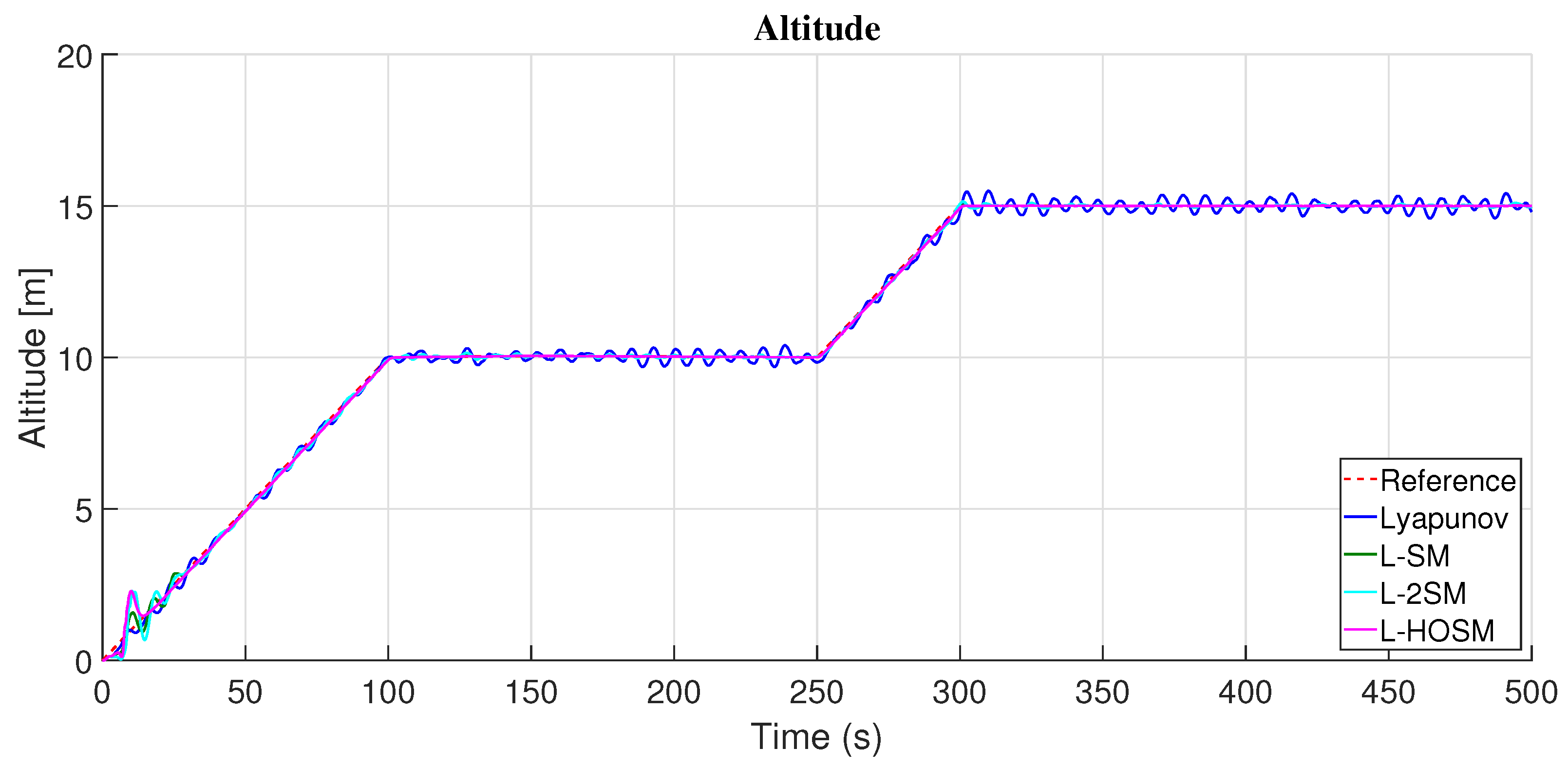
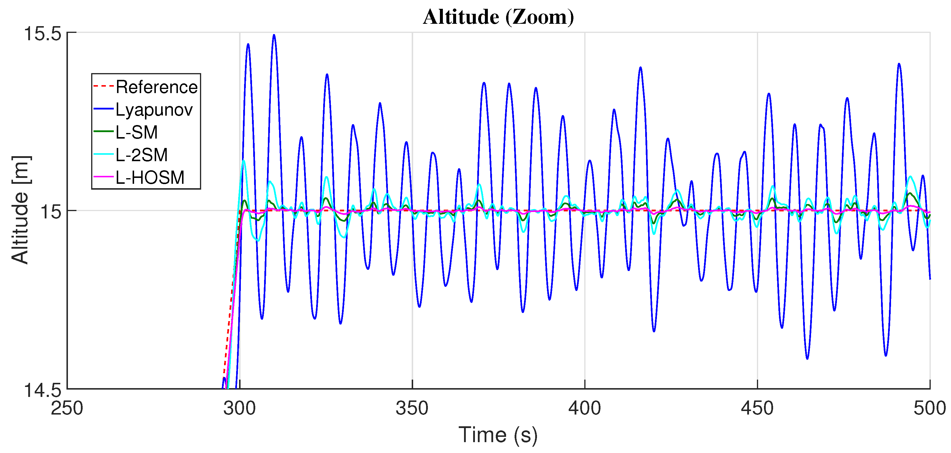
Figure 5 presents the results obtained with the PD adaptive controller and robust adjustment mechanism based on the Lyapunov and sliding mode theories. The adjustment mechanism to compare is the Lyapununov method (L), Lyapunov theory with first-order sliding mode (L-SM), Lyapunov theory with second-order sliding mode (L-2SM), and Lyapunov theory with high-order sliding mode (L-HOSM). And they are considering the numerical results obtained in Table 2 to analyze the adaptive control error Equation (33) and control effort Equation (34) with the different adjustment mechanisms. Then, the PD adaptive controller in altitude with the adjustment mechanism based on the Lyapunov theory with first-order sliding mode (L-SM) presented a smaller error than Lyapunov, L-2SM, and L-HOSM (see Table 2). Even to achieve the PD adaptive controller in altitude with the adjustment mechanism based on L-SM applied a smaller control effort than the adjustment mechanism based on Lyapunov, L-2SM, and L-HOSM (see Table 2).
On the other hand, in altitude, the PD adaptive controller, which presented a bigger error and control effort with the different adjustment mechanisms presented in this work, is based on the Lyapunov theory with high-order sliding mode (L-HOSM). Still, it should be mentioned that the adaptive PD controller with the adjustment mechanism L-HOSM presented a better response in the presence of wind gusts, see Figure 6. Even with the perturbations, the PD adaptive controller, with the adjustment mechanism based on the Lyapunov theory and first-order and second-order sliding modes, presented a significant response in the presence of perturbations by wind gusts. Then, in the presence of perturbations, the PD adaptive controller with the adjustment mechanism based on the Lyapunov theory without the sliding mode theory did not present a good performance, see Figure 6.
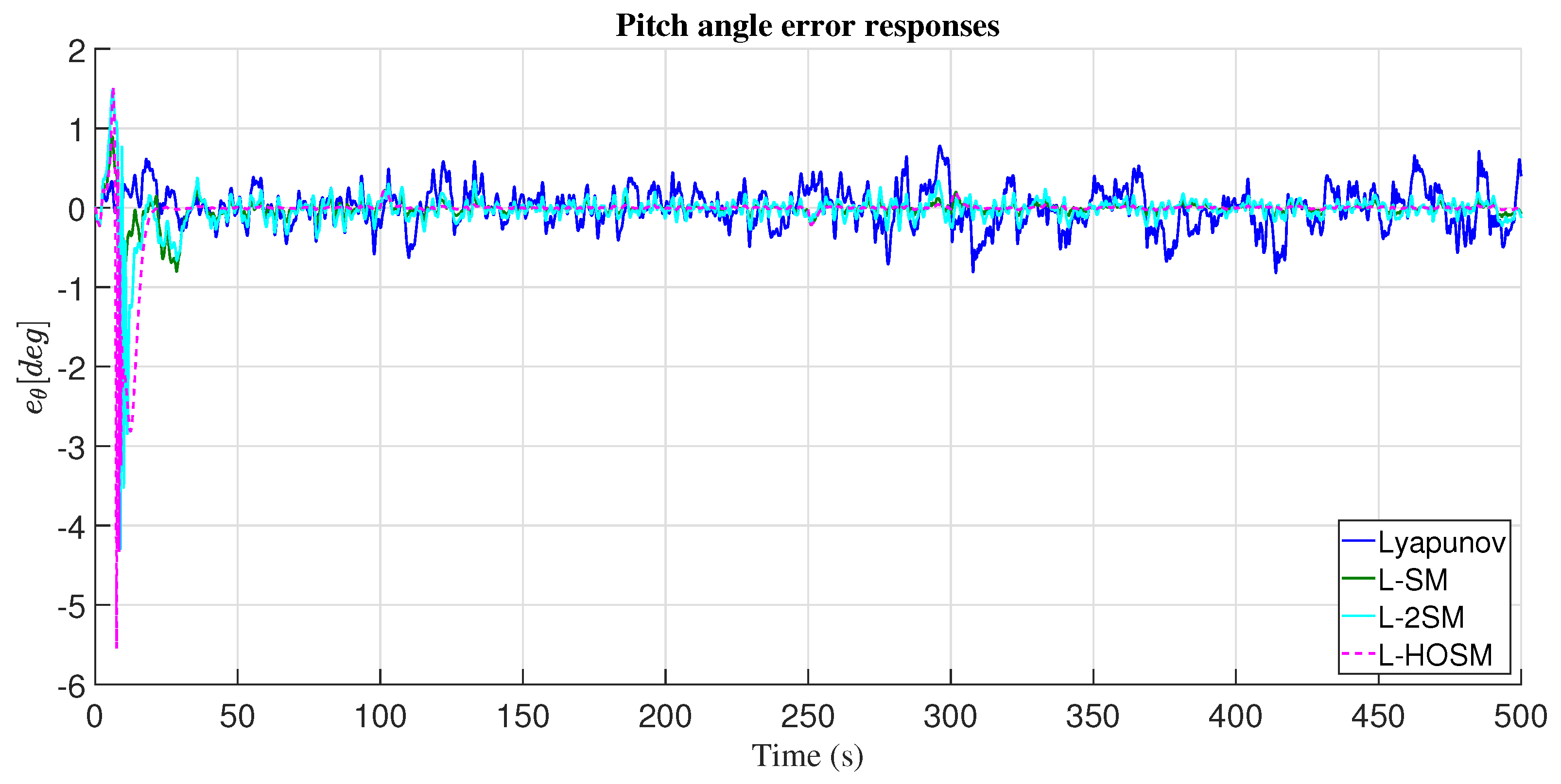
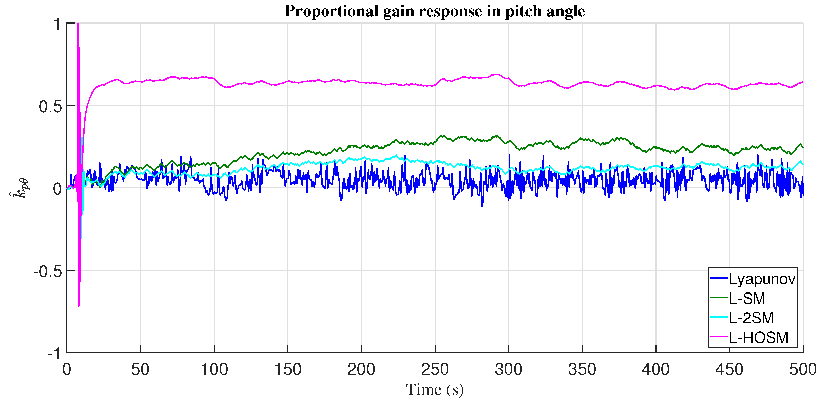
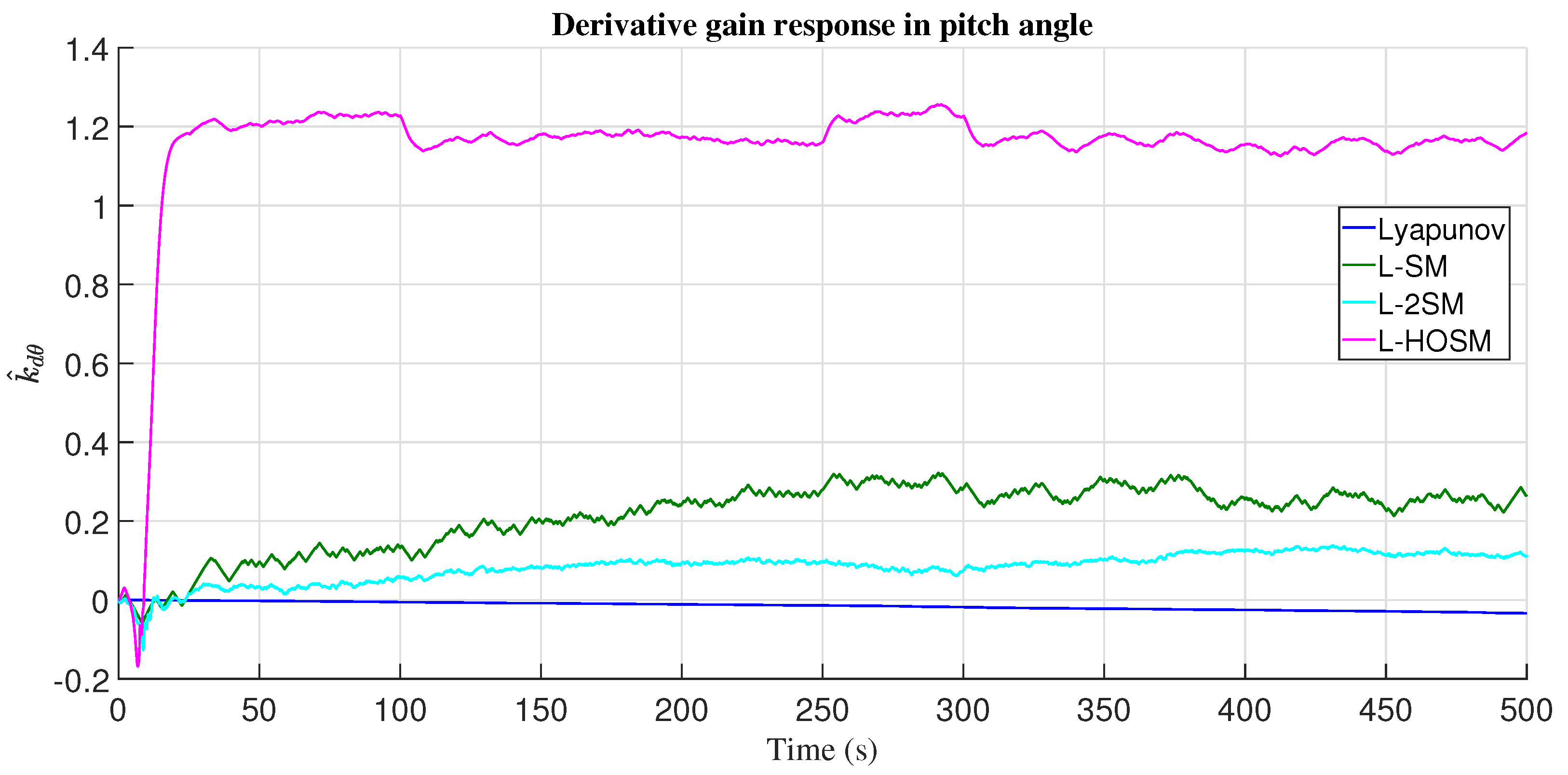
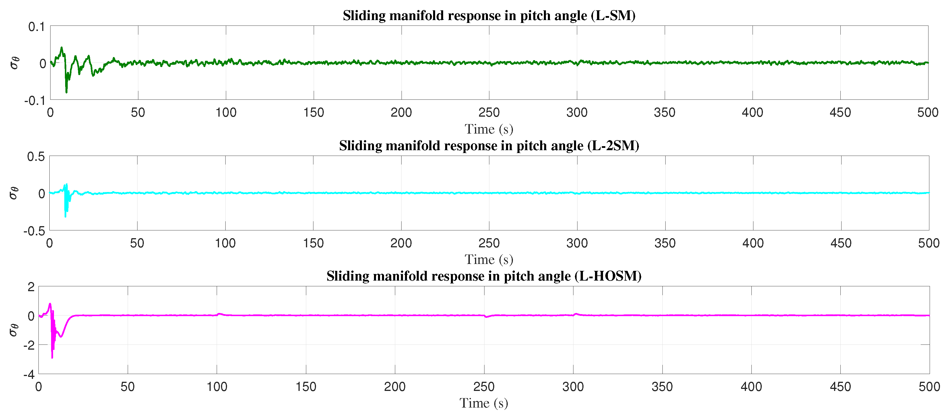
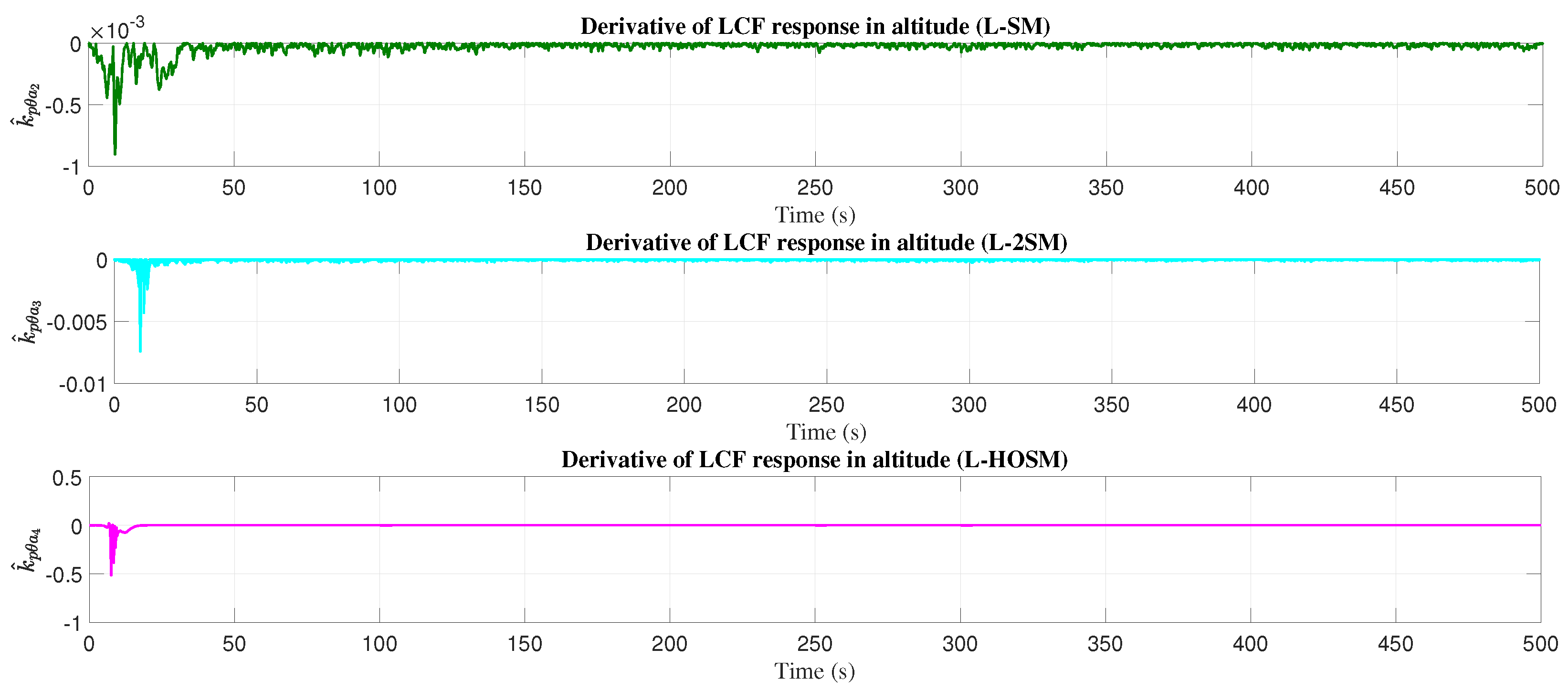
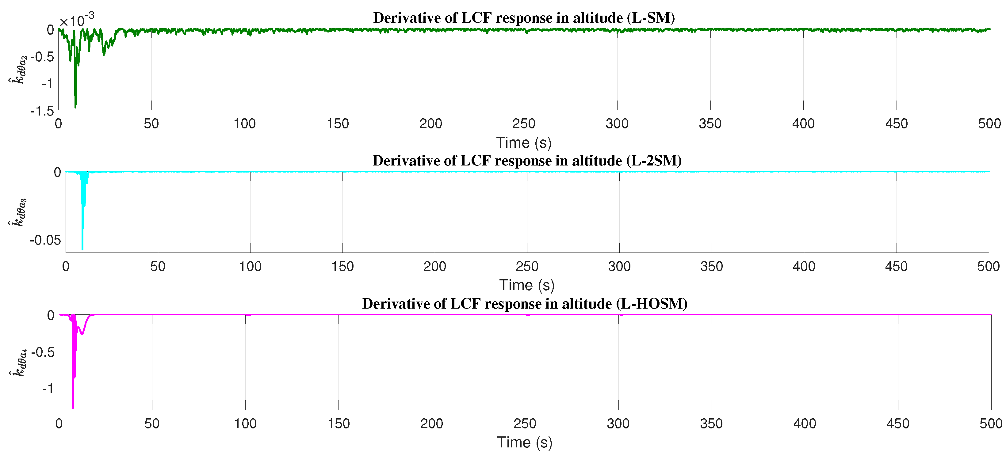
The control signal responses are presented in Figure 7, and the pitch error responses to achieve the desired altitude are shown in Figure 8. The responses of the adaptive proportional and derivative gains in altitude with perturbations, see Figure 9, Figure 10 and Figure 11, are presented in the sliding mode manifold graphics. The graphics of k ^ p and k ^ d derivatives for the LCF in altitude (with disturbances) are presented in Figure 12 and Figure 13. The total derivative of the LCF in altitude is presented in Figure 14.

4.2. Yaw Angle

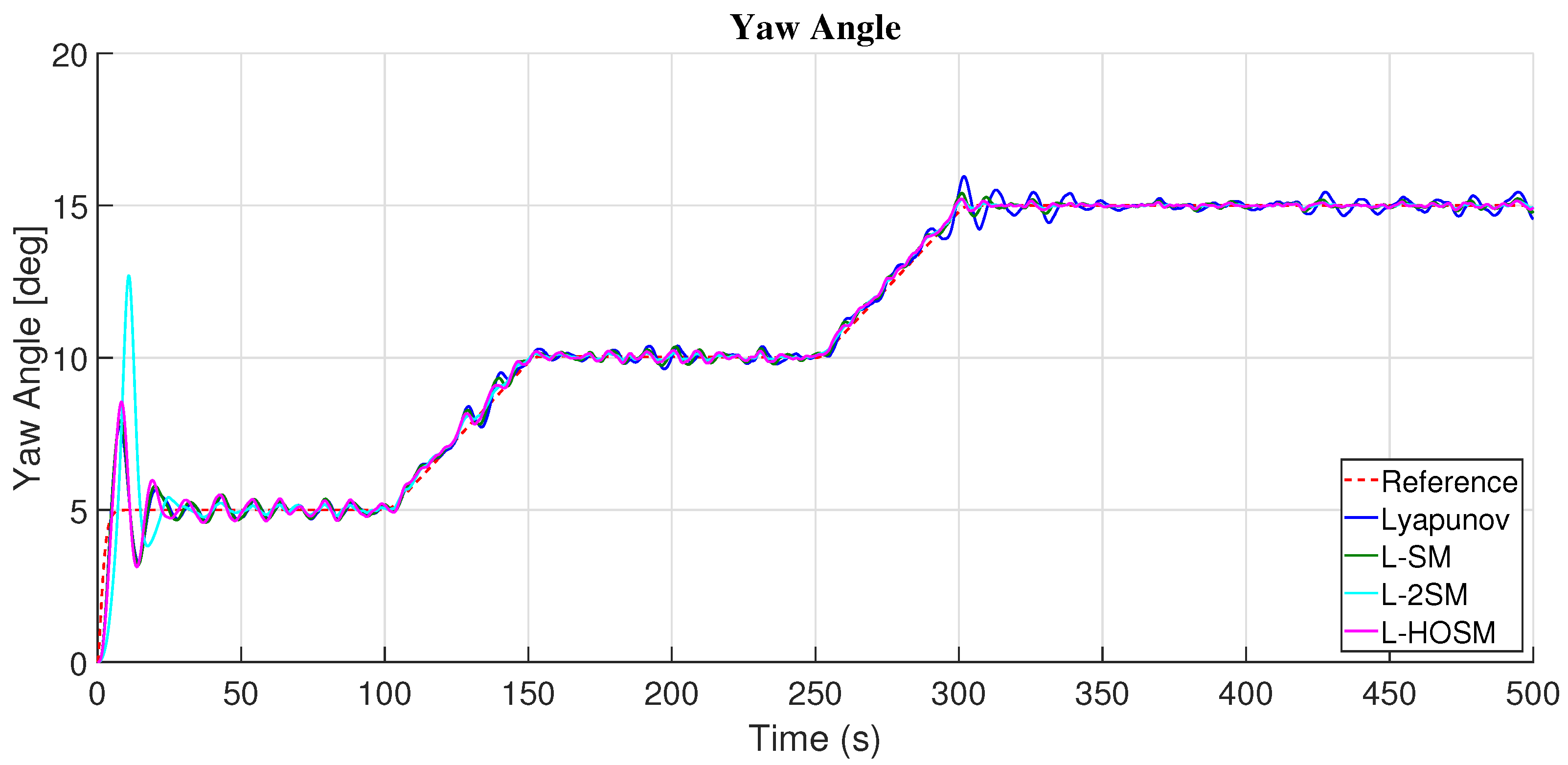
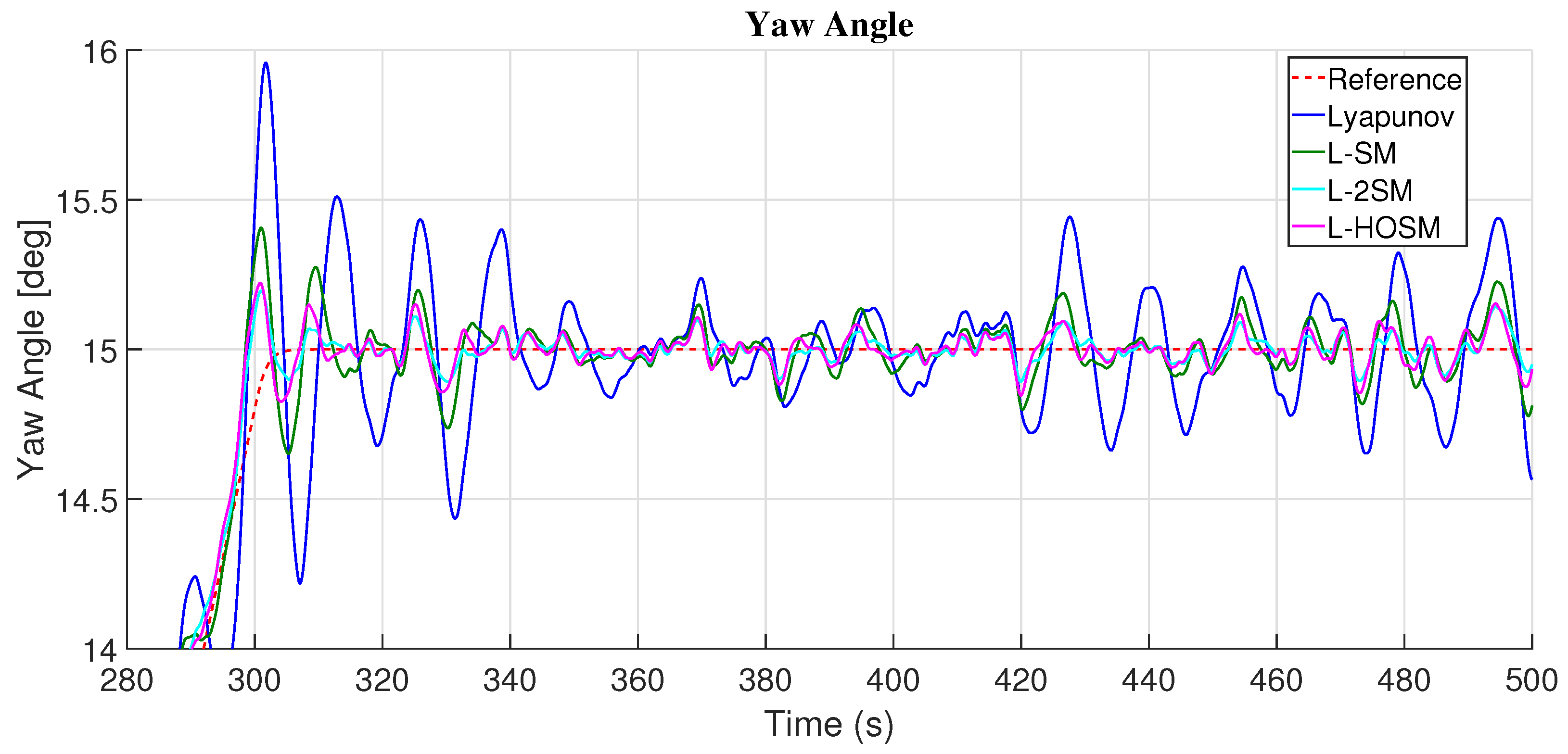
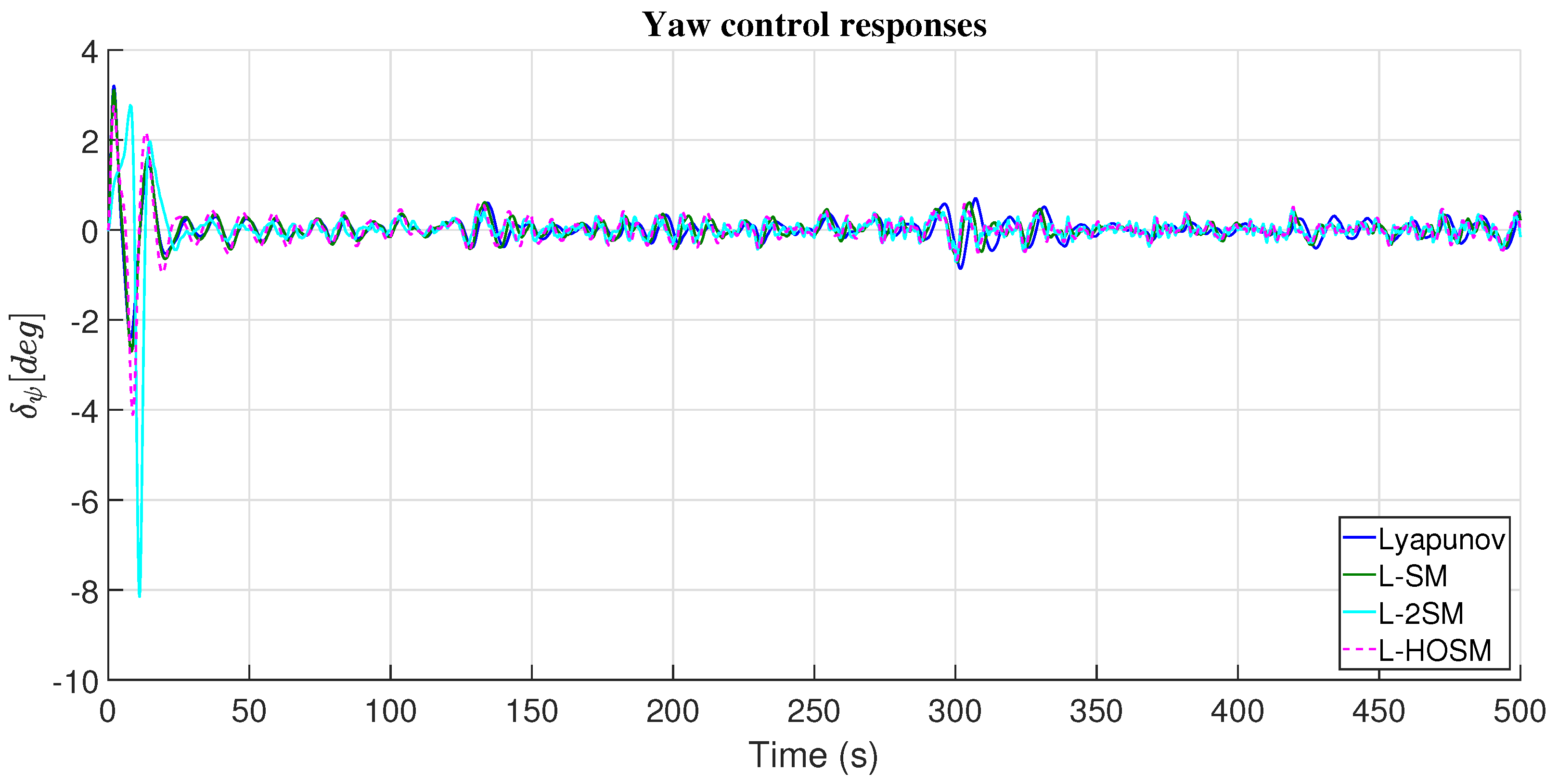
Figure 15 presents the results obtained to achieve a desired yaw angle in the fixed-wing MAV with the different adjustment mechanisms based on the Lyapunov theory with the sliding mode theory. The smaller yaw angle error was obtained with the adaptive PD controller with the adjustment mechanism based on the Lyapunov theory with the first-order sliding mode theory (L-SM). Still, the adjustment mechanism using only the Lyapunov theory (without the sliding mode theory) applied less control effort than the L-SM, see Table 2. Even the yaw error is smaller with the adjustment mechanism based on the Lyapunov theory than with the adjustment mechanism based on the Lyapunov theory with a second-order sliding model (L-2SM) and high-order sliding mode (L-HOSM), see Table 2. But, the use of the sliding mode theory in the adjustment mechanism is justified in the reduction in the perturbations by wind gusts, although it applied more control effort to achieve and stay near the desired yaw angle, Figure 16 depicts such perturbation reduction.
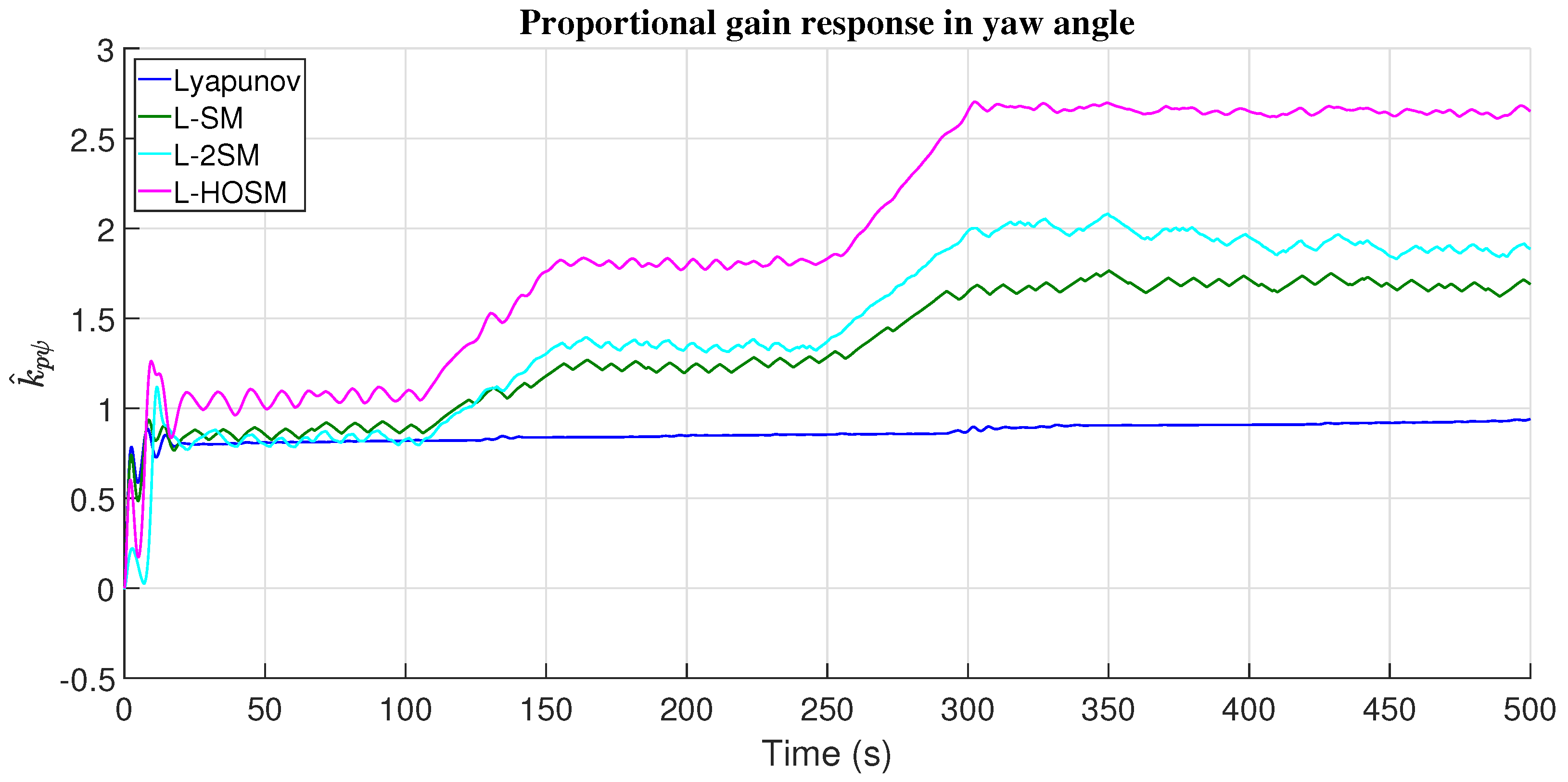
Figure 17 presents the yaw control effort to achieve the desired yaw angle with the adaptive PD controller and with the different adjustment mechanism, and Figure 18 shows the error in yaw angle. Figure 19 and Figure 20 represents the adaptive gains response of the PD controller with the different adjustment mechanisms. Figure 21 presents the sliding manifolds’ dynamic responses in the yaw angle.
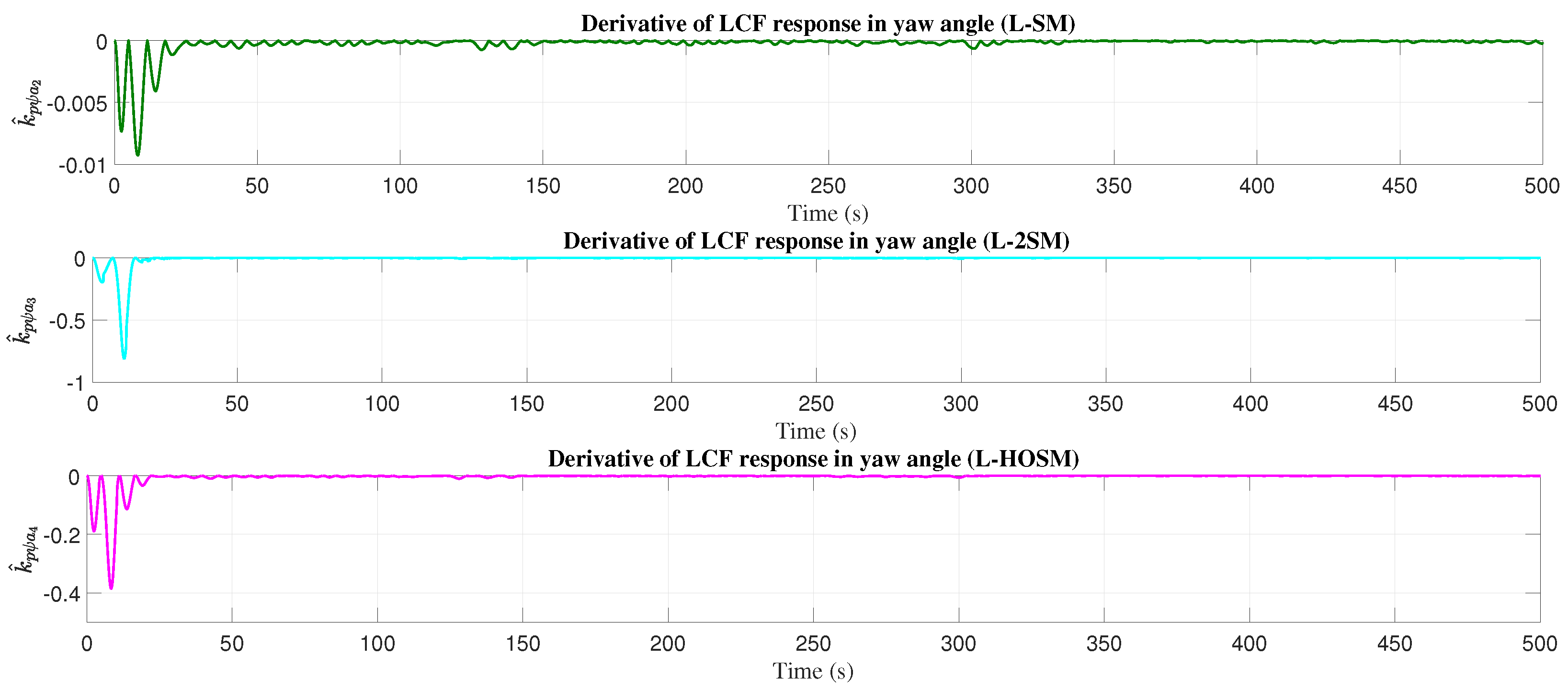
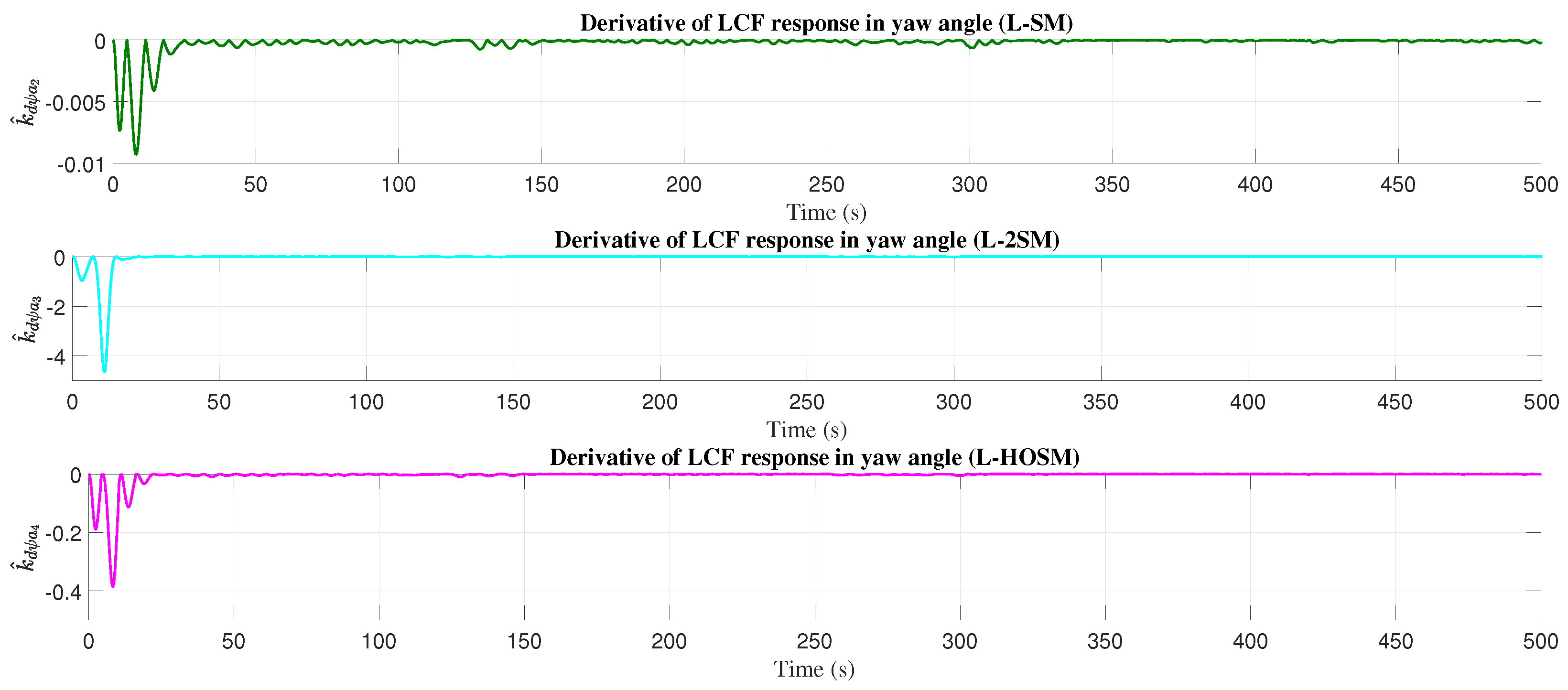
Figure 22 and Figure 23 show the graphics of k ^ p and k ^ d derivatives for the LCF in the yaw angle (with disturbances). The total derivative of the LCF in yaw angle is presented in Figure 24.

4.3. Roll Angle

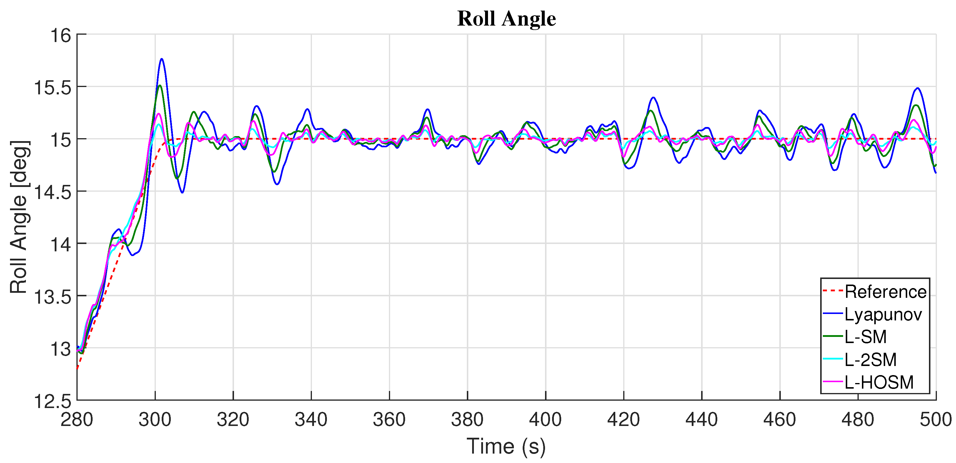
Figure 25 shows the results obtained with the adaptive PD in roll angle with the different adjustment mechanisms based on the Lyapunov theory and sliding mode theory. Then, the adaptive PD with the adjustment mechanism L-2SM presented the smaller error in roll angle, and the smaller control effort to achieve the desired roll angle is presented by the adjustment mechanism based on Lyapunov theory without sliding mode theory, see Table 2. The adjustment mechanism based on Lyapunov and first-order sliding mode (L-SM) presented a smaller error and control effort en roll angle than Lyapunov theory and Lyapunov theory with high-order sliding mode (L-HOSM) based on Table 2. Although the higher the error and control effort in comparison with the other adjustment mechanism, the better the response in the presence of perturbations by wind gusts is presented by the adjustment mechanism based on Lyapunov theory with high-order sliding mode (L-HOSM), see Figure 26.
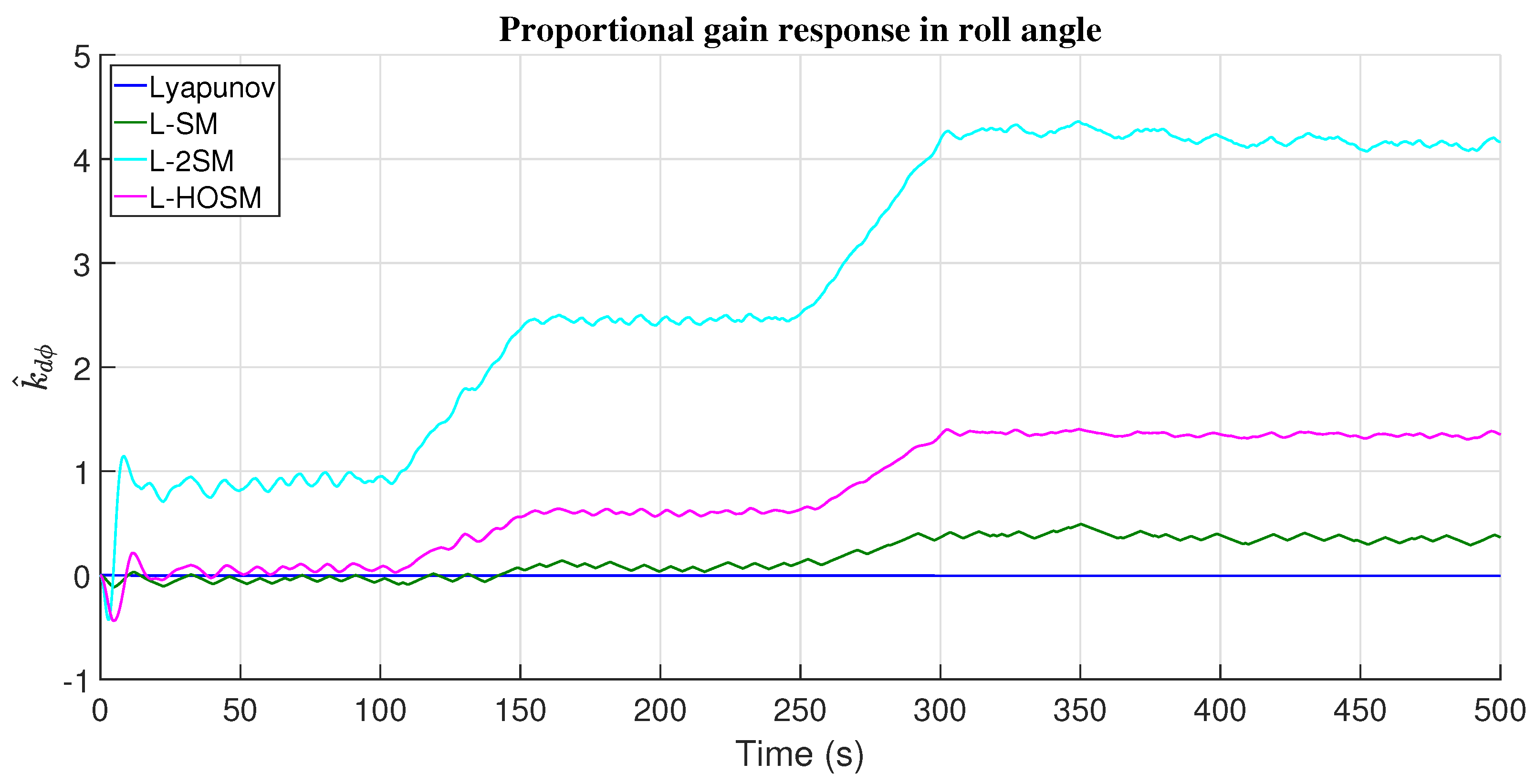
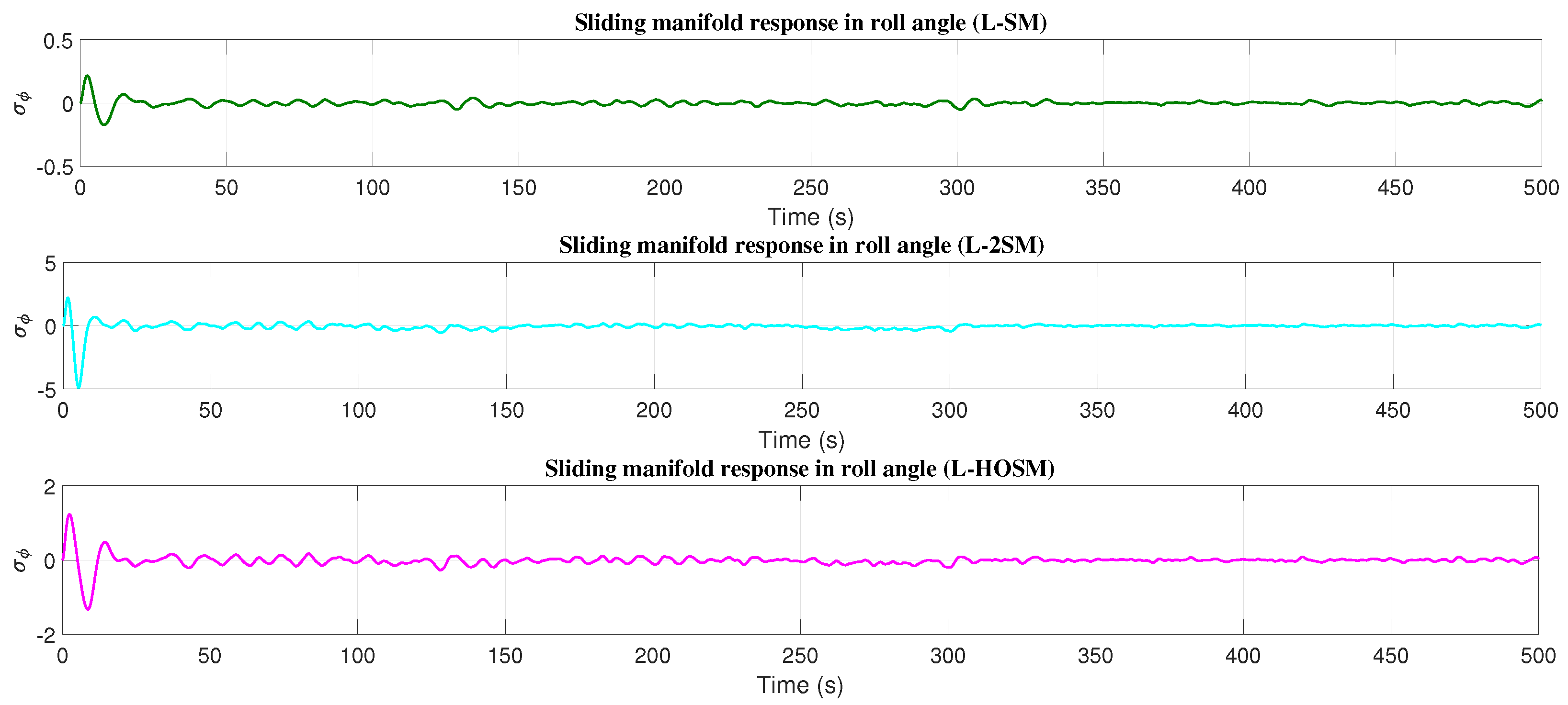
The control responses for the roll angle with the different adjustment mechanisms are presented in Figure 27. The graphics of the error in the roll angle are shown in Figure 28. Figure 29 and Figure 30 represent the proportional and derivative adaptive gains responses of the PD controller with the different adjustment mechanisms for the roll angle. The sliding manifold response for the roll angle is presented in Figure 31.
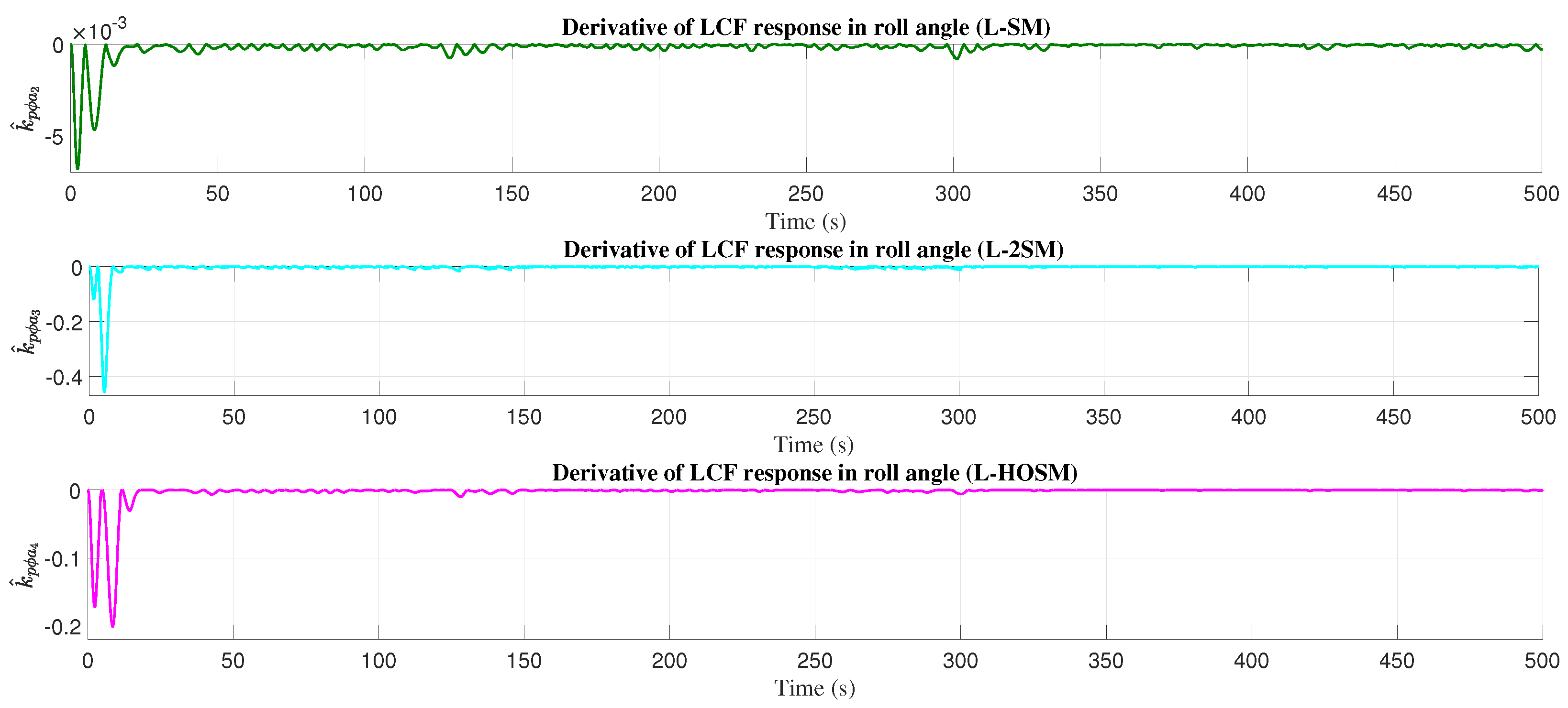
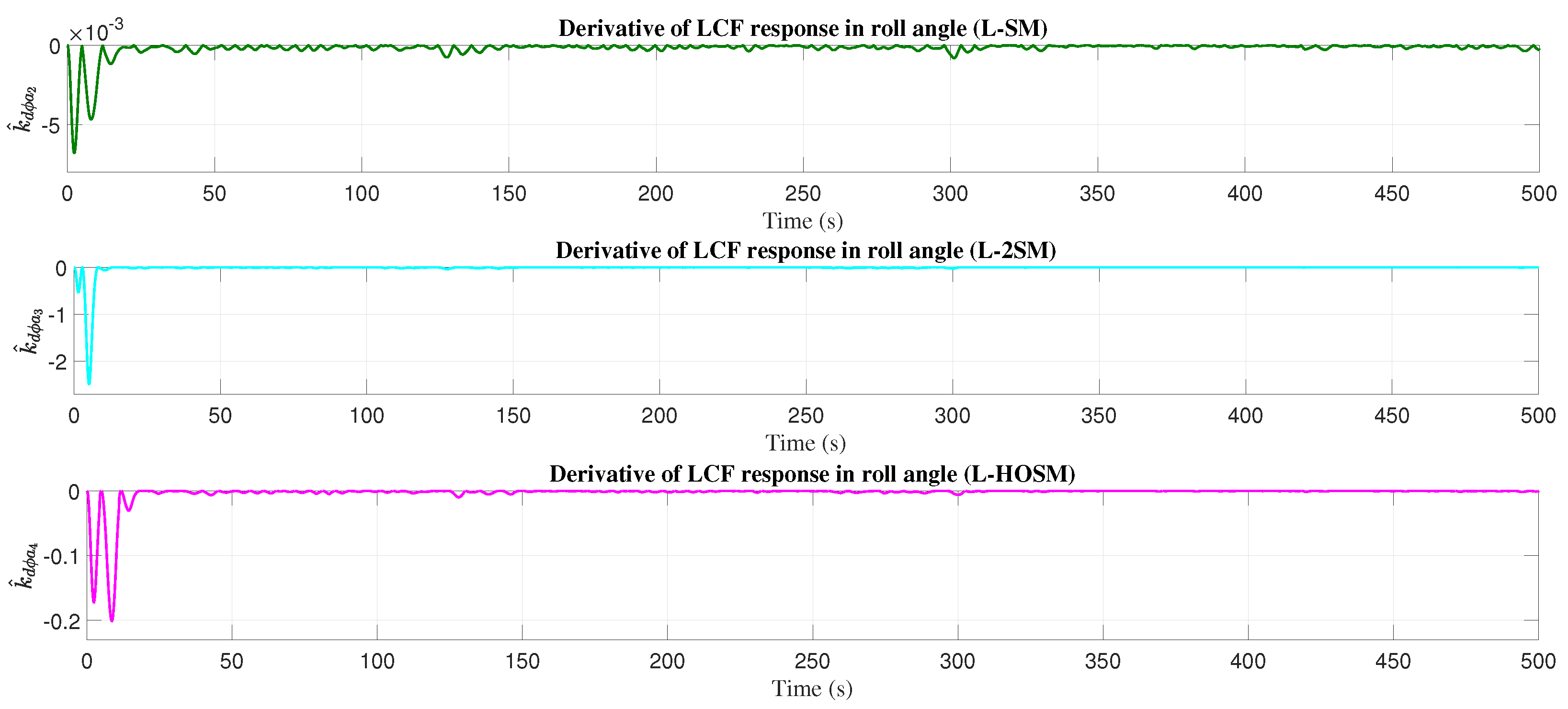
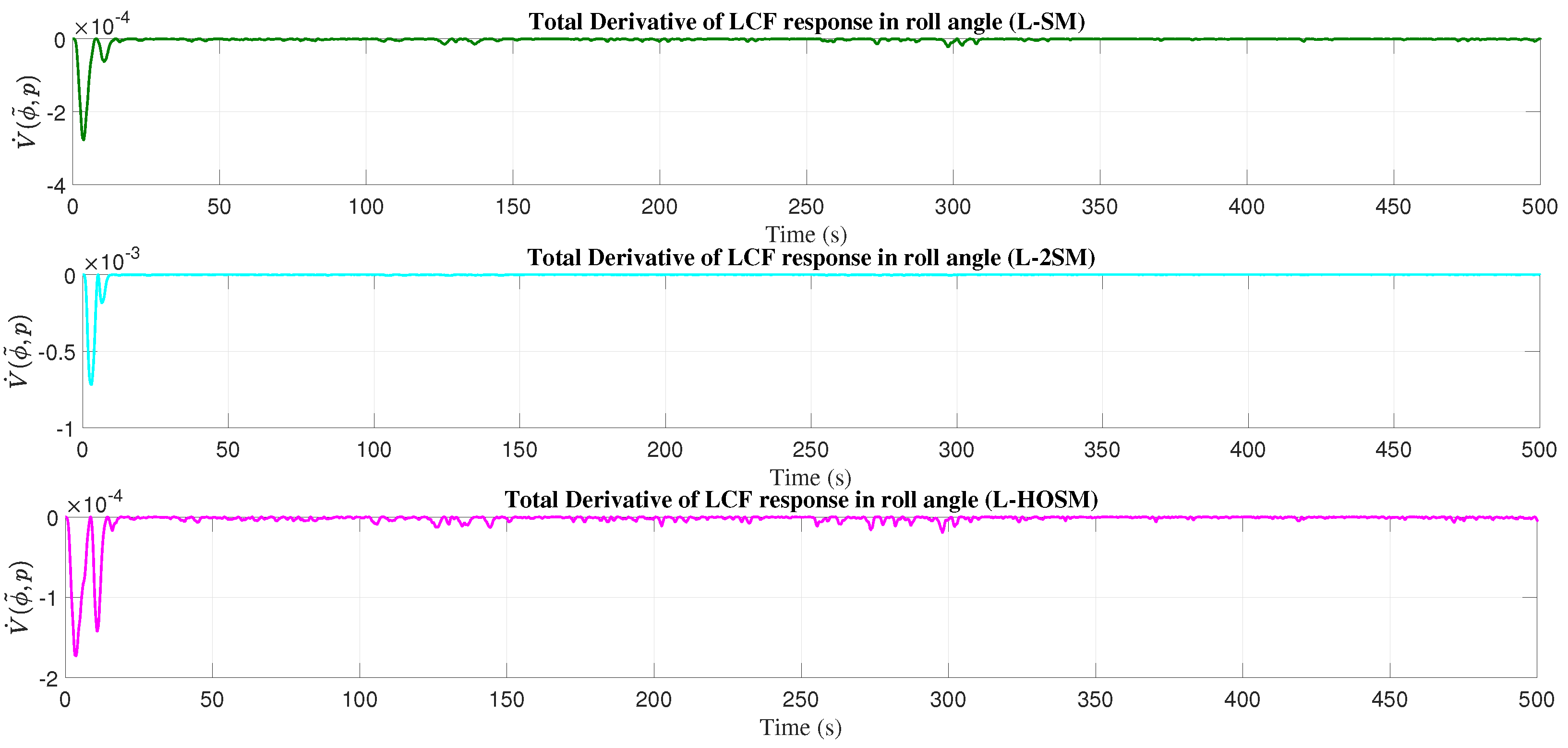
In Figure 32 and Figure 33, the graphics of k ^ p and k ^ d derivatives for the LCF for the roll angle (with disturbances) are presented. The total derivative of the LCF in roll angle is presented in Figure 34. The simulation results presented here can be observed in the video available in Supplementary Materials.

5. Discussion

This work has presented the results obtained after several simulations of an adaptive PD controller based on MRAS (Model Reference Adaptive System) using Lyapunov theory, and adding a sliding mode theory in the adjustment mechanism to attenuate or almost eliminate the unknown perturbations due to wind gusts.
Considering the analysis with the L 2 n o r m to know the error and control effort performance for every adjustment mechanism, a better response for altitude control was obtained with adaptive PD controller based on Lyapunov theory adding a sliding mode theory (L-SM) because a smaller error and control effort was presented to achieve the desired altitude, and the second best result in altitude was obtained with adjustment mechanisms based on Lyapunov theory without the sliding mode theory. However, it should be mentioned that the adjustment mechanism based on the second-order and high-order sliding mode significantly reduced the perturbations that are depicted in the figures called zoom-disturbances, even this perturbation reduction is depicted in the altitude, and for the yaw angle in the roll angle.
For the yaw angle, the adjustment mechanism that presented a better performance to achieve the desired roll angle is based on the Lyapunov theory with sliding mode, although it applied more control effort than the adjustment mechanism with Lyapunov theory without sliding mode theory because this last one presented a low response in the presence of unknown perturbations as has been shown in the figure zoom-disturbances in yaw angle. The adaptive PD controller presented a better response for the roll error angle with the adjustment mechanism based on Lyapunov theory, adding a first-order sliding mode (L-SM). However, although the adjustment mechanism with Lyapunov theory without sliding mode theory was presented as a minor control effort, the response in the presence of perturbations is not acceptable in comparison with the adjustment mechanism adding the sliding mode theory to the Lyapunov theory, and this has been depicted in the figure zoom-disturbances in the roll angle.
Thus, adding the sliding mode theory in the design of the adjustment mechanism based on the Lyapunov theory to reduce or almost eliminate the unknown perturbations by wind gusts had a significant effect.
A PID control law was not selected to design the adaptive controller because it is necessary to design another adaptive adjustment law for the integral action, and it takes more computer cost. For future work, first, we prefer to probe the adaptive PD proposed in this work in a real flight. It should be mentioned that the presence of sensor noise may significantly influence the comparison of different control laws.
Future work consists of developing a fixed-wing MAV testbed to analyze the adaptive control laws proposed in this work in a real flight.

Supplementary Materials

The following supporting information can be downloaded at: https://www.mdpi.com/article/10.3390/app14052198/s1.

Author Contributions

Conceptualization, T.E.-F. and A.S.; methodology, T.E.-F.; software, I.G.; validation, T.E.-F., A.S. and I.G.; formal analysis, W.G.; investigation, T.E.-F.; resources, I.G. and A.S.; data curation, A.S. and W.G.; writing—original draft preparation, T.E.-F.; writing-review and editing, A.S. and I.G.; visualization, A.S.; supervision, T.E.-F. and W.G.; project administration, T.E.-F.; funding acquisition, T.E.-F., A.S. and I.G. All authors have read and agreed to the published version of the manuscript.

Funding

This research received no external funding.

Institutional Review Board Statement

Not applicable.

Informed Consent Statement

Not applicable.

Data Availability Statement

The data presented in this study are available on request from the corresponding author. The data are not publicly available due to privacy.

Conflicts of Interest

The authors declare no conflicts of interest.

Abbreviations

The following abbreviations are used in this manuscript:
MRASModel Reference Adaptive System
MAVMini Aerial Vehicle
DOFDegrees of Freedom
SMCSliding Mode Control
HOSMHigh Order Sliding Mode
PDProportional-Derivative
PIDProportional-Integral-Derivative
L-SMLyapunov with Sliding Mode
L-2SMLyapunov with second-order Sliding Mode
L-HOSMLyapunov with High Order Sliding Mode

References

  1. Guo, Y.; Luo, L.; Bao, C. Design of a Fixed-Wing UAV Controller Combined Fuzzy Adaptive Method and Sliding Mode Control. Hindawi Math. Probl. Eng. 2022, 2022, 2812671. [Google Scholar] [CrossRef]
  2. Castañeda, H.; Salas-Peña, O.; León-Morales, J. Extended observer based on adaptive second order sliding mode control for a fixed wing UAV. ISA Trans. 2017, 66, 226–232. [Google Scholar] [CrossRef]
  3. Zheng, Z.; Jin, Z.; Sun, L.; Zhu, M. Adaptive Sliding Mode Relative Motion Control for Autonomous Carrier Landing of Fixed-wing Unmanned Aerial Vehicles. IEEE Access 2017, 5, 5556–5565. [Google Scholar] [CrossRef]
  4. Poksawat, P.; Wang, L.; Mohamed, A. Automatic Tuning of Attitude Control System for Fixed-wing Unmanned Aerial Vehicles. IET Control Theory Appl. 2016, 10, 2233–2242. [Google Scholar] [CrossRef]
  5. Thai, S.; Theodoulis, S.; Ross, C.; Biannic, J. Robust Gain-scheduled Autopilot Design with Anti-windup Compensation for a Guided Projectile. CEAS Aeronaut. J. 2023, 42, 765–786. [Google Scholar] [CrossRef]
  6. Poksawat, P.; Wang, L.; Mohamed, A. Gain Scheduled Attitude Control of Fixed-Wing UAV With Automatic Controller Tuning. IEEE Trans. Control Syst. Technol. 2018, 26, 1192–1203. [Google Scholar] [CrossRef]
  7. Chen, M.; Wang, Y. A Data-Driven Adaptive Method for Attitude Control of Fixed-Wing Unmanned Aerial Vehicles. Adv. Aerosp. Sci. Technol. 2019, 4, 1–15. [Google Scholar] [CrossRef]
  8. Bao, C.; Guo, Y.; Luo, L.; Su, G. Design of a Fixed-Wing UAV Controller Based on Adaptive Backstepping Sliding Mode Control Method. IEEE Access 2021, 9, 157825–157841. [Google Scholar] [CrossRef]
  9. Souanef, T. L1 Adaptive Path-Following of Small Fixed-wing Unmanned Aerial Vehicles in Wind. IEEE Trans. Aerosp. Electron. Syst. 2022, 58, 3708–3716. [Google Scholar] [CrossRef]
  10. Hussien, M.; Elnaggar, M.; Kamel, A.; Fattah, H. Unmanned Aerial Vehicle Attitude Control using L1 Adaptive Controller. IEEE Access 2021, 9, 131916–131925. [Google Scholar] [CrossRef]
  11. Melkou, L.; Hamerlain, M.; Rezoug, M. Fixed-Wing UAV Attitude and Altitude Control via Adaptive Second-Order Sliding Mode. Arab. J. Sci. Eng. 2018, 43, 6837–6848. [Google Scholar] [CrossRef]
  12. Sungjae, L.; Yosoon, C. Comparison of Topographic Surveying Results using a Fixed-wing and a Popular Rotary-wing Unmanned Aerial Vehicle (Drone). Tunn. Undergr. Space 2016, 26, 24–31. [Google Scholar]
  13. Espinoza, A.T.; Saenz, J.A.; del Río, O.; de Jesús Gómez, F.; López, N.V. Aplicaciones de Drones en Ingeniería Civil: Topografía, Inspección de Obra y Estructuras; Grupo, A., Ed.; AlfaOmega Editor: Ciudad de México, Mexico, 2021. [Google Scholar]
  14. Carabassa, V.; Montero, P.; Alcañiz, M.; Padró, J. Soil Erosion Monitoring in Quarry Restoration Using Drones. Minerals 2021, 11, 949. [Google Scholar] [CrossRef]
  15. Gulch, E. Photogeammetric measurements in Fixed-wing UAV Imagery. In Proceedings of the XXII ISPRS Congress, Melbourne, Australia, 25 August–1 September 2012. [Google Scholar]
  16. Martins, A.; Almeida, J.; Almeida, C.; Figueiredo, A.; Santos, F.; Bento, D.; Silva, H.; Silva, E. Forest Fire Detection with a Small Fixed-wing Autonomous Aerial Vehicle. IFAC Proc. Vol. 2007, 40, 168–173. [Google Scholar] [CrossRef]
  17. Mohsan, S.; Othman, N.; Li, Y.; Li, Y.; Alsharif, M.H.; Khan, M.A. Unmanned aerial vehicles (UAVs): Practical aspects, applications, open challenges, security issues, and future trends. Intell. Serv. Robot. 2023, 16, 109–137. [Google Scholar] [CrossRef]
  18. Templin, T.; Popielarczyk, D.; Kosecki, R. Application of Low-Cost Fixed-wing UAV for Inland Shoreline Investigation. Pure Appl. Geophys. 2018, 175, 3263–3283. [Google Scholar] [CrossRef]
  19. Šiljeg, A.; Marinovic, R.; Domazetovic, F.; Jurišic, M.; Marić, I.; Panđa, L.; Radočaj, D.; Milošević, R. GEOBIA and Vegetation Indices in Extracting Olive Tree Canopies Based on Very High-Resolution UAV Multispectral Imagery. Appl. Sci. 2023, 13, 739. [Google Scholar] [CrossRef]
  20. Alfonso-Torreño, A.; Gómez-Gutiérrez, A.; Schnabel, S. Dynamics of Erosion and Deposition in a Partially Restored Valley-Bottom Gully. Land 2021, 10, 26. [Google Scholar] [CrossRef]
  21. Stengel, R.F. Flight Dynamics; Princeton University Press: Princeton, NJ, USA, 2004. [Google Scholar]
  22. Goldstein, H.; Poole, C.; Safko, J. Classical Mechanics; Adison-Wesley: Boston, MA, USA, 1983. [Google Scholar]
  23. Stevens, B.; Lewis, F.; Johnson, E. Aircraft Control and Simulation, 3rd ed.; John Wiley and Sons: Hoboken, NJ, USA, 2015; ISBN 978-1-118-87098-3. [Google Scholar]
  24. Mclean, D. Automatic Flight Control Systems; Prentice Hall International: Hoboken, NJ, USA, 1990. [Google Scholar]
  25. Cook, M. Flight Dynamics Principles, 2nd ed.; Elsevier: Amsterdam, The Netherlands, 2007. [Google Scholar]
  26. Parada, R.; Espinoza, T.; Dzul, A.; Salas, F. Performance analysis of nonlinear observers applied to the fixed-wing unmanned aerial vehicles flight under decoupled-reduced model. Int. J. Micro Air Veh. 2017, 9, 111–123. [Google Scholar] [CrossRef]
  27. Espinoza, T.; Parada, R.; Dzul, A.; Lozano, R. Linear controllers implementation for a fixed-wing MAV. In Proceedings of the 2014 International Conference on Unmanned Aircraft Systems (ICUAS), Orlando, FL, USA, 27–30 May 2014. [Google Scholar]
  28. Espinoza, T.; Dzul, A.; Llama, M. Linear and Nonlinear Controllers Applied to Fixed-Wing UAV. Int. J. Adv. Robot. Syst. 2013, 10, 33. [Google Scholar] [CrossRef]
  29. Åström, K.; Wittenmark, B. Adaptive Control, 2nd ed.; Prentice Hall: Hoboken, NJ, USA, 1994. [Google Scholar]
  30. Kelly, R.; Santibañez, V.; Loría, L. Control of Robot Manipulators in Joint Space; Springer: London, UK, 2005. [Google Scholar]
  31. Shtessel, Y.; Shkolnikov, A. Aeronautical and Space Vehicle Control in Dynamic Sliding Manifolds; IFAC Robust Control Design: Milan, Italy, 2003. [Google Scholar]
  32. Sanchez, T.; Moreno, J. Design of lyapunov functions for a class of homogeneous systems: Generalized forms approach. Int. J. Robust Nonlinear Control 2018, 29, 661–681. [Google Scholar] [CrossRef]
  33. Levant, A.; Livne, M. Globally convergent differentiators with variable gains. Int. J. Control 2018, 91, 1994–2008. [Google Scholar] [CrossRef]
  34. Levant, A. Robust exact differentition via sliding mode technique. Automatica 1998, 34, 379–384. [Google Scholar] [CrossRef]
  35. Shtessel, Y.; Edwards, C.; Fridman, L.; Levant, A. Sliding Mode Control and Observation; Birkhäuser: New York, NY, USA, 2015. [Google Scholar]
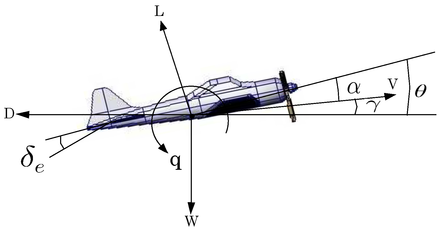
Figure 1. Pitch angle.
Applsci 14 02198 g001
Figure 2. Yaw angle.
Applsci 14 02198 g002
Figure 3. Roll angle.
Applsci 14 02198 g003
Figure 4. Block diagram.
Applsci 14 02198 g004
Figure 5. Response in altitude movement (with disturbances).
Applsci 14 02198 g005
Figure 6. Response in altitude movement (zoom-disturbances).
Applsci 14 02198 g006
Figure 7. Control signals in altitude (with disturbances).
Applsci 14 02198 g007
Figure 8. Error responses in altitude (with disturbances).
Applsci 14 02198 g008
Figure 9. Proportional gain in altitude (with disturbances).
Applsci 14 02198 g009
Figure 10. Derivative gain in altitude (with disturbances).
Applsci 14 02198 g010
Figure 11. Response of the sliding manifold in the proportional and derivative gain in altitude (with disturbances).
Applsci 14 02198 g011
Figure 12. k ^ p response of the derivative for the LCF in altitude (with disturbances).
Applsci 14 02198 g012
Figure 13. k ^ d response of the derivative for the LCF in altitude (with disturbances).
Applsci 14 02198 g013
Figure 14. V ˙ ( θ ˜ , q ) response of the total derivative for the LCF in altitude (with disturbances).
Applsci 14 02198 g014
Figure 15. Response in yaw angle (with disturbances).
Applsci 14 02198 g015
Figure 16. Response in yaw angle (zoom-disturbances).
Applsci 14 02198 g016
Figure 17. Control signals in yaw angle (with disturbances).
Applsci 14 02198 g017
Figure 18. Error responses in yaw angle (with disturbances).
Applsci 14 02198 g018
Figure 19. Proportional gain in yaw angle (with disturbances).
Applsci 14 02198 g019
Figure 20. Derivative gain in yaw angle (with disturbances).
Applsci 14 02198 g020
Figure 21. Response of the sliding manifold in the proportional and derivative gain in yaw angle (with disturbances).
Applsci 14 02198 g021
Figure 22. k ^ p response of the derivative for the LCF in yaw angle (with disturbances).
Applsci 14 02198 g022
Figure 23. k ^ d response of the derivative for the LCF in yaw angle (with disturbances).
Applsci 14 02198 g023
Figure 24. V ˙ ( ψ ˜ , r ) response of the total derivative for the LCF in yaw angle (with disturbances).
Applsci 14 02198 g024
Figure 25. Response in roll angle (with disturbances).
Applsci 14 02198 g025
Figure 26. Response in roll angle (zoom-disturbances).
Applsci 14 02198 g026
Figure 27. Control signals in roll angle (with disturbances).
Applsci 14 02198 g027
Figure 28. Error responses in roll angle (with disturbances).
Applsci 14 02198 g028
Figure 29. Proportional gain in roll angle (with disturbances).
Applsci 14 02198 g029
Figure 30. Derivative gain in roll angle (with disturbances).
Applsci 14 02198 g030
Figure 31. Response of the sliding manifold in the proportional and derivative gain in roll angle (with disturbances).
Applsci 14 02198 g031
Figure 32. k ^ p response of the derivative for the LCF in roll angle (with disturbances).
Applsci 14 02198 g032
Figure 33. k ^ d response of the derivative for the LCF in roll angle (with disturbances).
Applsci 14 02198 g033
Figure 34. V ˙ ( ϕ ˜ , p ) response of the total derivative for the LCF in roll angle (with disturbances).
Applsci 14 02198 g034
Table 1. Fixed-wing MAV parameters.
ParameterValue
ρ 1.05 kg/m3
S0.09 m2
c ¯ 0.14 m
b0.914 m
I x x 0.16 kg·m2
I y y 0.17 kg·m2
I z z 0.02 kg·m2
C m q −50
C m δ e 0.25
C n r −0.01
C n δ r 0.0005
C l p −0.15
C l δ a 0.005
V60 km/h
Table 2. L 2 n o r m error and control effort.
Adaptive Mechanism (Altitude) L 2 [ e h m ] L 2 [ u θ ]
Lyapunov0.01840.0060
Lyapunov-SM (L-SM)0.00810.0036
Lyapunov-2SM (L-2SM)0.02170.0150
Lyapunov-HOSM (L-HOSM)0.04510.0274
Adaptive Mechanism
(Yaw angle)
L 2 [ e ψ m ] L 2 [ u ψ ]
Lyapunov0.03790.0351
Lyapunov-SM (L-SM)0.03620.0360
Lyapunov-2SM (L-2SM)0.07140.0591
Lyapunov-HOSM (L-HOSM)0.29760.2881
Adaptive Mechanism
(Roll angle)
L 2 [ e ϕ m ] L 2 [ u ϕ ]
Lyapunov0.02840.0249
Lyapunov-SM (L-SM)0.02790.0253
Lyapunov-2SM (L-2SM)0.02610.0470
Lyapunov-HOSM (L-HOSM)0.25280.2386
Disclaimer/Publisher’s Note: The statements, opinions and data contained in all publications are solely those of the individual author(s) and contributor(s) and not of MDPI and/or the editor(s). MDPI and/or the editor(s) disclaim responsibility for any injury to people or property resulting from any ideas, methods, instructions or products referred to in the content.