Article

Numerical Heat Transfer Simulation of Oil Shale Large-Size Downhole Heater

1
College of Construction Engineering, Jilin University, Changchun 130026, China
2
National-Local Joint Engineering Laboratory of In-Situ Conversion, Drilling and Exploitation Technology for Oil Shale, Changchun 130026, China
3
Provincial and Ministerial Co-Construction of Collaborative Innovation Center for Shale Oil & Gas Exploration and Development, Changchun 130026, China
4
Key Lab of Ministry of Natural Resources for Drilling and Exploitation Technology in Complex Conditions, Changchun 130026, China
*
Author to whom correspondence should be addressed.
Appl. Sci. 2024, 14(6), 2235; https://doi.org/10.3390/app14062235
Submission received: 30 January 2024 / Revised: 23 February 2024 / Accepted: 4 March 2024 / Published: 7 March 2024
(This article belongs to the Section Applied Thermal Engineering)

Abstract

:
Downhole heaters are critical for effectively achieving in situ oil shale cracking. In this study, we simulate the heat transfer performance of a large-scale helical baffle downhole heater under various operational conditions. The findings indicate that at 160 m3/h and 6 kW the outlet temperature can reach 280 °C. Controlling heating power or increasing the injected gas flow effectively mitigates heat accumulation on the heating rod’s surface. The outlet temperature curve exhibits two phases. Simultaneously, a balance in energy exchange between the injected gas and heating power occurs, mitigating high-temperature hotspots. Consequently, the outlet temperature cannot attain the theoretical maximum temperature, referred to as the actual maximum temperature. Employing h / p 1 3 as the indicator to evaluate heat transfer performance, optimal performance occurs at 100 m3/h. Heat transfer performance at 200 m3/h is significantly impacted by heating power, with the former being approximately 6% superior to the latter. Additionally, heat transfer performance is most stable below 160 m3/h. The gas heating process is categorized into three stages based on temperature distribution characteristics within the heater: rapid warming, stable warming, and excessive heating. The simulation findings suggest that the large-size heater can inject a higher flow rate of heat-carrying gas into the subsurface, enabling efficient oil shale in situ cracking.

1. Introduction

Oil shale [1], a sedimentary rock containing hydrocarbon substances, has the potential to produce hydrocarbons with varying carbon content through accelerated thermal development of internal hydrocarbon compounds by external energy input [2,3,4]. Surface retorting and in situ cracking are the fundamental methods for processing oil shale [5,6]. In alignment with the national low-carbon policy and the imperative for sustainable development [7], in situ pyrolysis is poised to become the predominant method for extracting oil shale in the future.
In prior studies, oil shale reservoirs were typically discovered at depths exceeding 50 m [8,9]. The downhole heater has emerged as the optimal choice for mitigating heat loss attributed to conductive heat from the surface. Downhole heaters are categorized into two types based on their heat generation mechanisms: combustion heaters and electric heaters [10,11,12,13]. Concerning downhole stability, combustion heaters significantly lag behind electric heaters [14,15]. Consequently, electric heaters are the more prevalent choice in the in situ conversion process [16,17].
Royal Dutch Shell conducted an oil shale pilot project to experiment with in situ electric heating extraction technology (E-ICP) and developed a Y-type electric heater for heating the oil shale layer through heat conduction [18,19]. This type of heater operates on three-phase electricity, providing high heating power, but it necessitates a high-quality oil shale reservoir. Wang pioneered U-type and LU-type electric heaters. In contrast to Y-type electric heaters, U-type electric heaters are typically oriented horizontally, rendering them more suitable for the development of thin layers of oil shale [8]. Nevertheless, their construction can pose challenges. Due to the limited heat transfer area of the exposed electrode, the thermal conductivity efficiency of the reservoir is diminished, leading to prolonged heating times [20,21]. Certain researchers advocate utilizing electric heating rods as the energy source and optimizing heat transfer structure to achieve an ideal thermal state in the flow. This approach has emerged as the primary focus in the current design of heaters [22,23,24].
Based on a heater’s shell flow pattern, it can be divided into a segmental baffle board structure and a helical baffle structure [25,26,27,28]. The segmental baffle structure is commonly used because it is simple, but the presence of a flow dead zone and a local high-temperature zone limits the usage of electric heaters [29,30,31]. On the contrary, the fluid in the shell has a helical baffle board structure similar to plunger flow with great heat transfer efficiency, flow uniformity, and no flow dead zone. As a result, the heat transmission performance of a helical baffle is superior to that of a segmental baffle, while the former generates and loses less entropy than the latter under the same Reynolds number situation. Song conducted an investigation into the performance of continuous helical baffle heat exchangers featuring varying dip angles. In comparison to the heat exchanger with a 21° dip angle, the heat transfer coefficient and pressure drop for the heat exchanger with an 11° dip angle experienced reductions of 86% and 52%, respectively [32]. Yang introduced the concept of a multiple-shell tube heat exchanger, wherein fluid undergoes a sequential flow through both inner and outer shell processes [33]. The investigation focused on a continuous helical baffle combined multi-shell tube heat exchanger. While the multi-shell tube heat exchanger exhibits higher heat transfer coefficients and pressure drops compared to the segmental baffle shell tube heat exchanger, the former attains a superior heat transfer coefficient at an equivalent pressure drop. Wang conducted a numerical analysis on the performance of a combined multi-shell continuous helical baffle heat exchanger. Under similar mass flow rates and heat exchange quantities, the combined multi-shell heat exchanger exhibited a 13% lower average pressure drop compared to it [34,35].
From 2012 to 2022, Jilin University conducted an in situ oil shale conversion pilot project at various depths in Nong’an and Fuyu City, Jilin Province. All these projects successfully yielded shale oil [36]. While the downhole heater plays a crucial role, the technical implementation process reveals many questions such as slow heating efficiency and limited heating volume. Previously studied downhole heaters had small, fixed shell dimensions constrained by the well diameter. Consequently, to enhance the efficiency of in situ oil shale conversion, this paper utilizes the Nong’an and Fuyu oil shale in situ pilot projects as an engineering foundation. It proposes the design of a large-size continuous helical baffle heater to offer technical insights for on-site construction.

2. Materials and Methods

Jilin University implemented two types of heaters, namely a segmental baffle and a helical baffle, in field applications through the establishment of pilot project bases in Nong’an and Fuyu. Both types have operated successfully. The deployment of heaters in the subsurface has indirectly enhanced the efficiency of in situ oil shale conversion, as shown in Figure 1 and Figure 2.
To enhance the efficiency of in situ oil shale heating, this paper introduces the design of a large-size helical baffle downhole heater. The heater’s physical model (Figure 3) is composed mostly of the heater shell, continuous helical baffle, center tube, and heating rods. Given the vertical orientation of the heater in the borehole, the z-axis was chosen as the direction of gravitational acceleration. The specific parameters of the heater are listed in Table 1.
The computational domain in this study adopted no-permeability, no-slip, and adiabatic boundary conditions. Meshing was used to define the heater’s mesh, and localized, appropriate refinement was applied in the vicinity of the heating rods and shells. The mesh used was a hexahedral mesh with a quantity of 2,502,315 and a mesh-independent validation grid was utilized to ensure the model converged accurately to meet the accuracy requirements. The air inlet temperature was 283 K and the outlet was a pressure outlet boundary, which followed the constant temperature boundary condition T w = 873 K.
In this paper, the following assumptions for numerical simulations were made:
  • The shell-side fluid was a fully developed turbulent flow in a steady state;
  • The fluid in the helical channel was incompressible;
  • The heat dissipation on the external wall of the shell cylinder was ignored;
  • The heating rods were regarded as walls with a constant heat flux density;
  • The specific heat capacity of air, thermal conductivity, and dynamic viscosity with temperature were fitted by segmented polynomials, and density was considered a constant.
The heater shell process gas follows the following equations during flow:
The mass conservation equation:
u ¯ i x i = 0
The momentum conservation equation:
( ρ u ¯ i ) t + ( ρ u ¯ i u ¯ j ) x j = p ¯ x i + X j ( μ e f f u ¯ i x j ρ u i ¯ u i ¯ u ¯ j )
The energy conservation equation:
t ρ E + x i u i ρ E + p = x i k e f f T x i j h j J j + u j τ i j e f f + S h
The renormalization group (RNG) k - ε model was used to provide fully developed flows with high streamline curvature for the model, and the options ‘enhanced wall treatment’ and ‘thermal effects’ were selected. The universal governing equation of the mass, energy, momentum, and RNG k - ε turbulent viscosity is expressed as follows:
d i v ρ U Φ = d i v Γ Φ g r a d Φ + S Φ
where U is the velocity vector, Φ is a universal variable representing, u i , Τ , k , ε or another variable, Γ Φ is a generalised diffusion coefficient, and S Φ is a generalised source term.
The commercial computational fluid dynamics (CFD) software FLUENT 2020 R2 was used to calculate the shell-side flow and heat transfer. The SIMPLE algorithm was adopted to address the coupling between the velocity and pressure, while the momentum, energy, and turbulence parameters were solved using the second-order upwind scheme. The default values of the under-relaxation factors were used for the pressure, momentum, and turbulent kinetics. For the continuity equation, the residual values of u i , Τ , and ε were controlled on the order of 10−5, and the energy parameters of the residual values were controlled on the order of 10−7. The calculation results were deemed to be converged when the corresponding parameters reached the residual values during the iterative calculation.

3. Results

In this study, the previously mentioned heater model was employed in each case. For all tests, the two independent variables were heating power (kW) and injection flow rate (m3/h). Three flow rates and three power values were employed to assess temperature distribution characteristics, outlet temperature response, and comprehensive heater performance. A flow rate of 160 m3/h and a heating power of 6 kW were used to analyze the distribution trend of the heating rod’s surface temperature. The heating power described in this article refers to the heating power of a single heating rod.

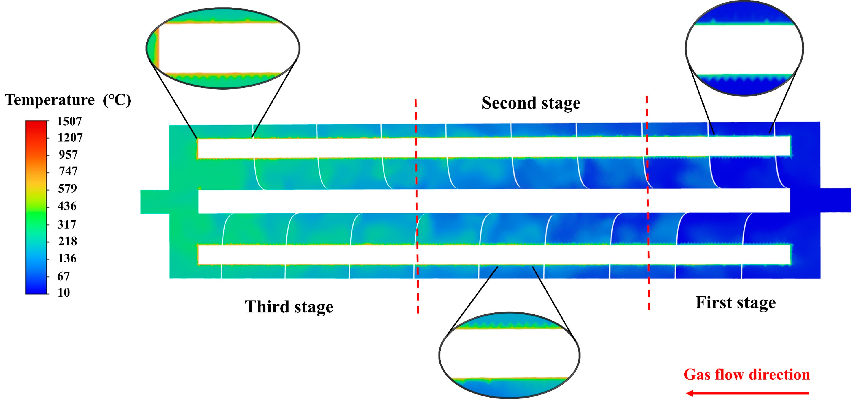
3.1. Heating Rod Surface Temperature

According to Fourier’s formula, a rapid increase in gas temperature due to significant heat exchange occurred in this region. Additionally, there was no helical baffle at the gas entrance to impede the gas flow. As depicted in Figure 4, the higher the gas turbulence intensity and the faster the gas stripping rate at the heater wall, the more effective the heat transfer on the surface of the heating rod. With the increase in gas temperature, the shell Reynolds number and heat transfer coefficient gradually decreased and stabilized, leading to a corresponding variation in temperature over time. The exit temperature could reach 280 °C, sufficient for the maturation of oil shale. As the gas flow distance in the shell increased, the heat exchange effect diminished rapidly, resulting in noticeable heat accumulation on the surface of the heating rod and the generation of a high-temperature hot spot. The presence of this phenomenon is adverse to the long-term operation of the heater in the well and reduces the heater’s service life.
As depicted in Figure 5, reducing the heating power or increasing the injected gas flow rate effectively diminished the distribution area and density of high-temperature hot spots on the heating rod’s surface. Both approaches mitigate heat accumulation on the heating rod’s surface, thereby preventing the formation of high-temperature hot spots. However, the author contends that reducing the heating power of the heating rod is more practical in real-world working environments. This preference arises from two factors. First, adjusting the heating power of a heating rod to regulate its surface temperature is a widely employed engineering technique that is both versatile and applicable. Second, increasing the injected gas flow to reduce heat accumulation is constrained by the length of the heater shell, and the longer the heater shell, the less effective this method becomes. The underlying reason for this lies in the fact that with a longer shell length, the injected gas is heated for a more extended period, and the hot spot at the gas outlet persists.
Simultaneously, oil shale reservoirs are often thin and unevenly dispersed, and the length of the heater’s shell cannot be indefinitely extended due to the actual geological characteristics. Moreover, a sudden increase in gas injection flow rate can impact the in situ conversion process. For instance, controlling the injected gas flow rate is a crucial step in the autothermic pyrolysis in situ conversion process for oil shale exploitation. A sudden increase in the injected gas flow rate lowers the temperature of the cracking zone, hindering the formation of autothermic chain pyrolysis reactions.

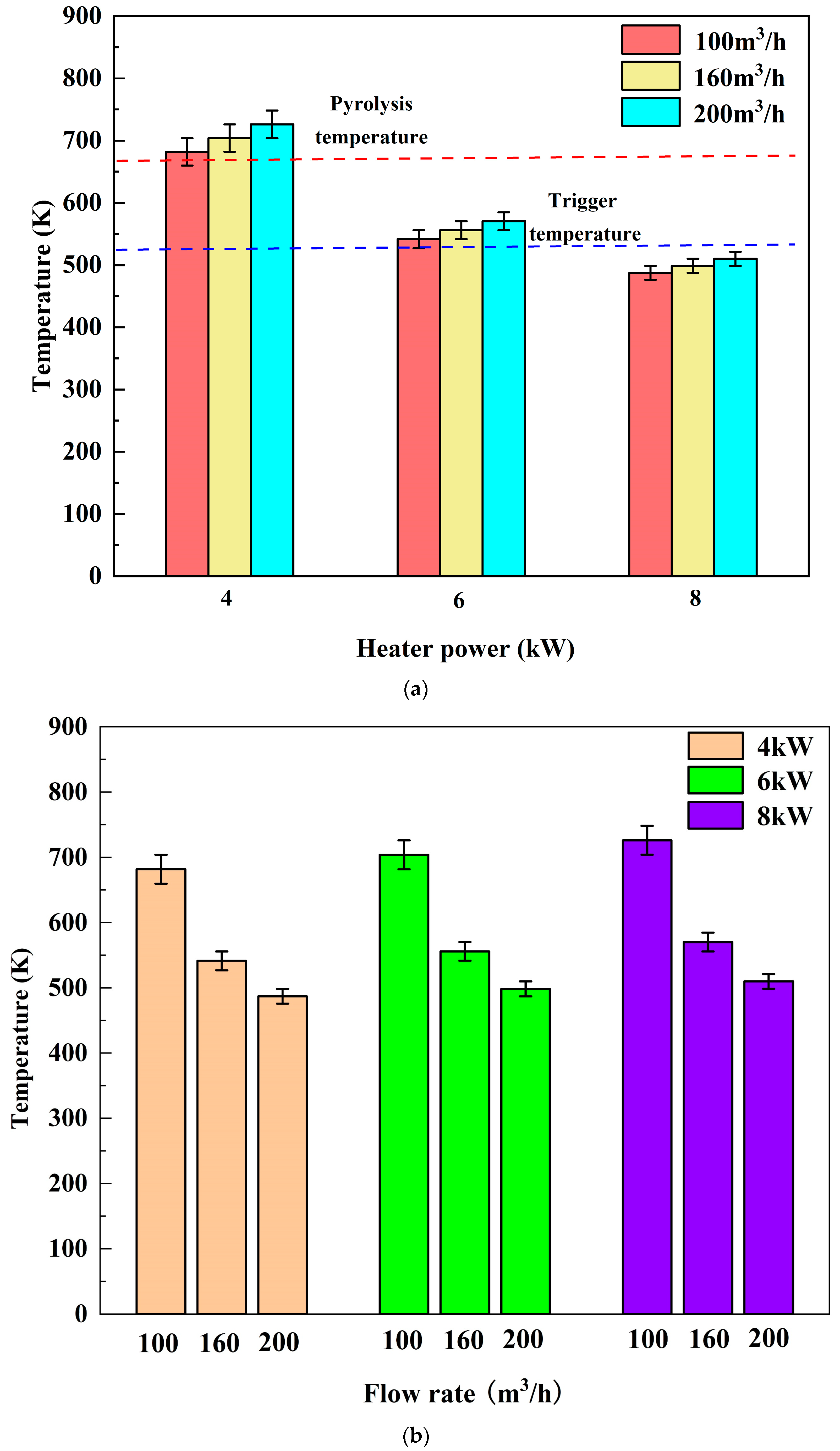
3.2. Outlet Temperature Response Characterization

Figure 6 illustrates the heater outlet temperature curve. It is evident that the gas heating rate increases steadily, progressing in roughly two stages. In the first stage, there is a substantial temperature gradient between the gas and the heating rod, resulting in rapid gas heating. In the second stage, the gas temperature rises rapidly, and the temperature gradient with the surface of the heating rod decreases rapidly. According to Fourier’s formula, a smaller temperature difference requires a longer heating time to reach the same temperature. Observing the gas heating process in the heater shell reveals that, as the gas flows through the same shell length, the temperature increase in the second stage is smaller than that in the first stage, and this temperature increase further diminishes with increasing shell length.
As a result, a theoretical maximum value exists for the heater’s outlet temperature, referred to as the theoretical temperature here.
As illustrated in Figure 7, the maximum outlet temperature is 762.16 K at 100 m3/h and 8 kW, while the minimum is 487.283 K at 200 m3/h and 4 kW. Previous research indicates that the temperature can reach the oil shale cracking temperature at 100 m3/h but not the triggering temperature at 200 m3/h. At heating powers of 4 kW, 6 kW, and 8 kW, the maximum outlet temperature occurs at 100 m3/h, 160 m3/h, or 200 m3/h, with corresponding temperature increases of 3.3%, 6.5%; 2.7%, 5.3%; or 2.3%, 4.7%. A lower temperature increase at 200 m3/h is mainly attributed to the excessively rapid gas flow rate and insufficient heating power at that level. Conversely, the highest temperature increase at 100 m3/h is primarily due to the slower gas flow rate and an extended heating period, leading to a significantly higher outlet temperature than under other working conditions.
The observation indicates that the flow rate is too rapid to adequately heat the gas and too sluggish for repeated heating. Consequently, the authors deduce that, in the current simulation, a balanced working condition exists, mitigating both of these situations. The outlet temperature is most suitable at 160 m3/h and 4 kW, signifying that the heating power and gas flow rate attain an energy exchange balance, as shown in Figure 5 and Figure 7. Therefore, to sustain the energy exchange balance, the outlet temperature cannot reach the theoretical temperature. This implies that, for the lifetime of the heater and to maintain the corresponding flow conditions, the outlet temperature must remain below the theoretical temperature, referred to as the actual temperature.

3.3. Comprehensive Performance

Because of the incompressibility of gas, it adopts a plunger flow pattern constrained by a helical baffle, as observed in Figure 8 and Figure 9. The gas flow rate in the shell is uniform, and there is no flow dead zone. The pressure distribution in the shell decreases linearly along the Z-axis, yet noticeable localized pressure anomalies occur at the front of the center tube and at the exit. This is primarily attributed to variations in fluid flow diameter. Upon entering the interior of the heater, the space becomes significantly larger, increasing several times compared to the space in the gas pipeline, resulting in fluctuations in the gas flow rate. At the exit, the gas flow is precisely the opposite of that at the entrance. When combined with the temperature distribution shown in Figure 4 and Figure 5, the pressure abnormal area does not adversely impact the heater’s heat transfer performance. However, it is more likely to compromise the support of the center tube to the helical baffle, and if lost cannot provide a helical flow constraint to the injected gas.
The heater shell process gas follows the following equations during flow:
The Prandtl number expression is defined as follows:
P r = C p · μ λ
The Reynolds number (Re) is defined as follows:
R e = d e u s ρ μ
The Nusselt number ( N u ) is defined as follows:
N u = C R e m P r 1 3
where C p is isobaric specific heat capacity ( J kg · K ), μ is gas viscosity ( Pa · s ), λ is thermal conductivity ( W m · K ), d e is hydraulic diameter (m), u s is the velocity of the shell side (m/s), and ρ is density ( k g / m 3 ), C = 0.59, m = 0.25.
According to Equations (5)–(7), as the gas is gradually heated within the heater shell, the temperature rises, and the Prandtl number of the gas decreases, resulting in an increase in gas viscosity. As a consequence, the Nusselt number of the heater decreases. Furthermore, as the gas undergoes heating, its viscosity steadily increases along the gas flow path. Concurrently, the local differential pressure resistance and friction resistance of the heater in the well increase, resulting in a further reduction in the flow rate of the injected gas. Owing to these various impacts, the duration of gas heating in the rear end of the shell is prolonged. Subsequently, the heat transfer efficiency of the heater’s rear section decreases, resulting in the formation of high-temperature hot spots on the surface of the heater rod. This, in turn, affects the long-term stable operation of the heater.
The heat transfer coefficient h / p 1 3 serves as a key indicator for evaluating heat transfer performance. The primary objective of a downhole heater is to achieve efficient heat transfer. The significance of the average heat transfer coefficient at the heater rod wall surpasses that of the heater pressure drop. Heat transfer is most efficient at 100 m3/h and is significantly influenced by heating power at 200 m3/h, as depicted in Figure 10. The former outperforms the latter by approximately 6%. Moreover, at 160 m3/h, the heat transmission performance is at its most stable. It can be deduced that the heat transfer structure significantly influences heat transfer performance, and so do the power of the heating rod and the gas injection condition. Therefore, by adjusting the injected gas flow rate and heating power across a wide range, not only can the heating requirements of different methods be met, but efficient heat transfer cracking can also be achieved.

4. Discussion

4.1. Heater Temperature Characterization

Investigating the temperature distribution of a large-size heater is crucial for its optimal utilization and the implementation of in situ high-efficiency heat transfer. The temperature distribution in the heater, as illustrated in Figure 5, can be categorized into three phases under the conditions of a flow rate of 160 m3/h and a heating power of 6 kW. The first stage is the rapid warming stage, predominantly occurring in the front section of the heater shell. During this stage, the temperature of the injected gas experiences a rapid increase, with a substantial temperature difference between the surface of the heating rod and the injected gas. This leads to a notable heat transfer effect and minimal heat accumulation on the surface of the heating rod. The second phase is a stable warming stage primarily distributed in the central part of the heater shell. During this stage, the temperature rises steadily, and the injected gas flows uniformly within the constraints of the helical baffle. At this point, the injected gas and the surface of the heater rod maintain a significant temperature gradient, resulting in effective heat transmission. However, this effect is inferior to that of the first stage, leading to heat accumulation on the surface of the heater rod in some locations. The third stage is the excessive heating stage primarily occurring at the rear end of the heater shell. During the first two phases, the injected gas is heated, and the temperature gradient with the surface of the heating rod is further reduced in this stage, leading to poor heat transfer and a significant amount of heat accumulation on the surface of the heating rod. Simultaneously, as the gas temperature rises, the gas viscosity gradually increases, slowing the flow rate and causing the gas at the same shell distance to overheat.

4.2. Field Application Measures

In situ cracking in the field has revealed that, in addition to the oil shale reservoir’s low thermal conductivity, the limited flow rate of heated gas that can be injected plays a significant role in the difficulty to heat oil shale reservoirs on an extensive scale. In comparison to earlier research [34,37], it is clear that the downhole heater is limited by the well diameter, the inner volume of the shell range is tiny, and it cannot heat a big flow rate of gas; the maximum volume flow rate is approximately 150 m3/h. When compared to typical downhole heaters, large-sized heaters can greatly improve heating efficacy. As indicated in Figure 4, the lowest output temperature among the nine circumstances mentioned in this study is 487.283 K. Gas injection can still be utilized to heat the reservoir over time. The advantage of a larger downhole heater is that it offers a wider range of operating state adjustment intervals. Heating needs for in situ oil shale cracking can be met using either convection (>380 °C) or combustion (<380 °C) methods [1]. In addition to the harsh formation environment, persistent high-temperature heating of downhole heaters during operation can cause fatigue damage to the heater itself. According to Section 3.1, raising the injected gas flow rate reduces heat accumulation on the heating rod surface and adjusts the heater’s working state. That is, using the large-size heater discussed in this paper, the injection of hot medium from the well at higher temperatures can be achieved, and at the same time, the long-term working time of the downhole heater can be realized by adjusting the control parameters, which indirectly makes the in situ high-efficiency heating of oil shale possible. In the field, the results of numerical simulation may be affected by the heater’s material and the downhole high-temperature corrosion conditions, resulting in a degree of influence on the heater’s heating performance and a degree of error with the numerical simulation results. As a result, the simulation findings are not without limits.

5. Conclusions

The numerical heat transfer simulation of a large-size downhole heater was performed under a number of parameter settings, and the simulation findings essentially met the research target of injecting a huge flow of high-temperature gas into the well. As a result, only the conditions simulated in this research can yield the following conclusions:
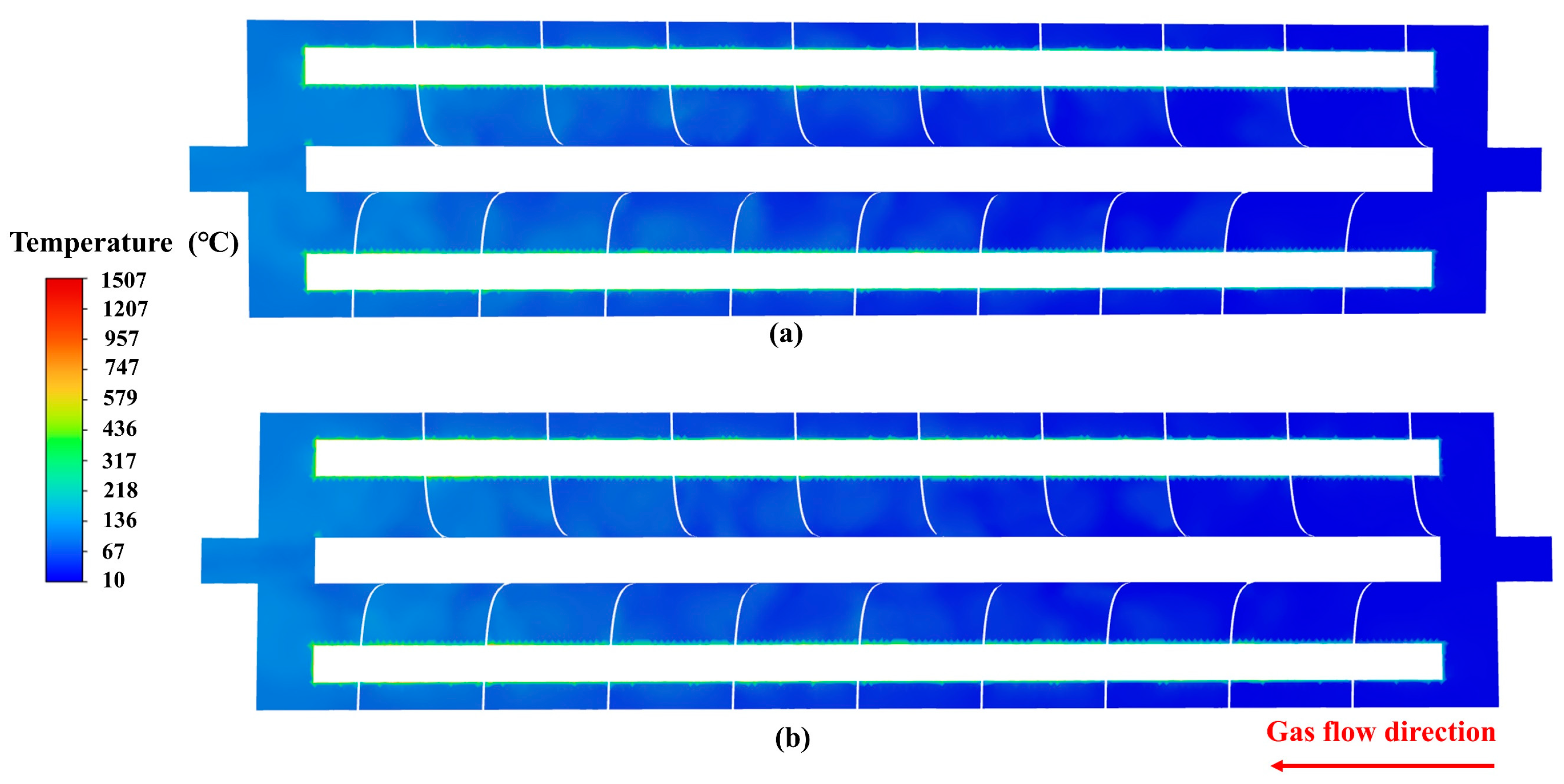
  • Upon injecting gas into the heater, the gas temperature rapidly increases due to the absence of helical baffle constraints at the gas input, leading to enhanced heat transmission. As the gas temperature rises, it essentially reaches the temperature required for oil shale maturation at the output. Heat accumulates on the surface of the heating rod as the temperature gradient with the gas decreases. Lowering the heating power while increasing the injected gas flow rate can reduce the distribution area and density of high-temperature hot spots on the heating rod’s surface. In practical working conditions, the authors believe that reducing the heating power of the heating rod is more feasible.
  • The gas heating rate at the outlet exhibits two stages, with a diminished temperature rise as the shell length increases and a theoretical maximum value for the heater’s outlet temperature. An energy exchange balance between heating power and injected gas flow rate ensures more efficient energy utilization and extends the heater’s service life. As a result, the outlet temperature, also referred to as the actual temperature, cannot surpass the theoretical temperature in this operational situation.
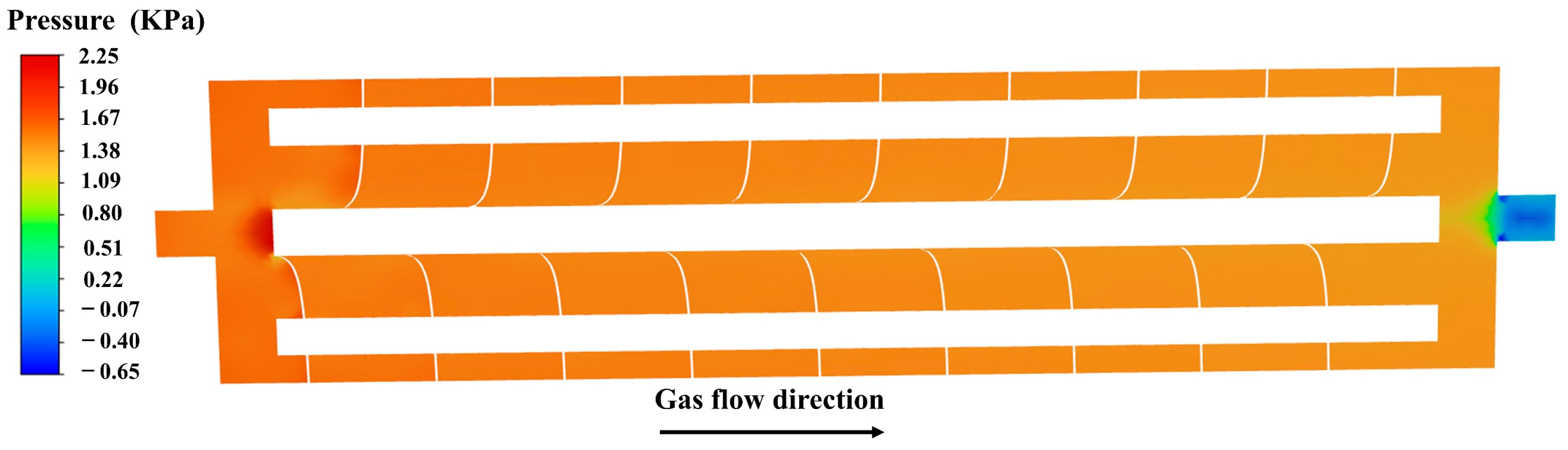
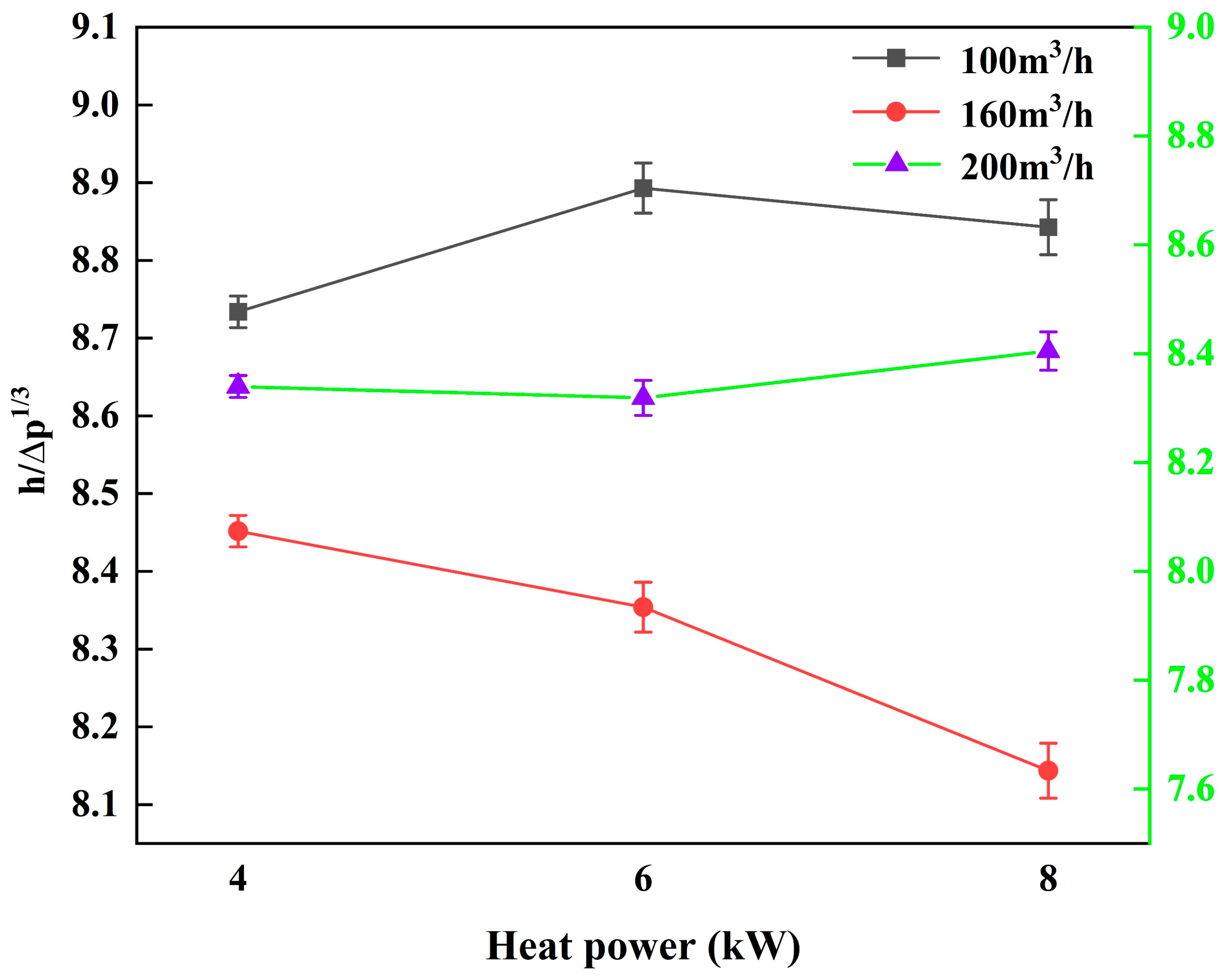
  • The pressure distribution in the shell decreases linearly. Gas viscosity gradually increases as the gas flow channel lengthens. Simultaneously, the local differential pressure resistance and frictional resistance of the heater in the well increase, causing a further decline in the flow rate of the injected gas. Adopting h / p 1 3 as the heat transfer performance evaluation index, it was found that the optimal heat transfer performance was attained at 100 m3/h. However, heat transfer performance was notably impacted by heating power at 200 m3/h, with the former surpassing the latter by approximately 6%. Moreover, heat transfer performance was most stable at 160 m3/h.
  • The gas heating stage of the heater was characterized by a rapid warming stage, a steady warming stage, and an over-heating stage, determined by the temperature distribution and temperature change on the surface of the heating rods. Due to the larger size of the heater, a greater volume and area can be utilized for the heating rods, enhancing the heater’s heating performance. Controlling the flow rate of the injected gas and the heating power enables efficient in situ heating of the oil shale.

Author Contributions

Conceptualization, Q.B. and Q.L.; software, Q.L.; validation, X.L., Q.L. and Q.B.; formal analysis, X.L.; investigation, Q.L.; resources, Q.L.; data curation, Q.B.; writing—original draft preparation, Q.B.; writing—review and editing, Q.B.; supervision, X.L.; project administration, X.L; funding acquisition, Q.L. All authors have read and agreed to the published version of the manuscript.

Funding

This research was funded by the National Key R&D Program of China (Grant No.2019YFA0705502, Grant No.2019YFA0705501), the Young and Middle-aged Excellent Team Project for Scientific and Technological Innovation of Jilin Province of China (Grant No.20220508135RC), the Independent Innovation Capacity Project of Jilin Province Development and Reform Commission (Grant No.2022C021) the Program for JLU Science and Technology Innovative Research Team (Grant No.2020TD-05), and the Fundamental Research Funds for the Central Universities.

Institutional Review Board Statement

Not applicable.

Informed Consent Statement

Not applicable.

Data Availability Statement

The data provided in this study can be provided at the request of the corresponding author. Due to the involvement of subsequent research progress, the data has not been made public.

Conflicts of Interest

The authors declare no conflicts of interest.

References

  1. He, W.T.; Sun, Y.H.; Shan, X.L. Organic matter evolution in pyrolysis experiments of oil shale under high pressure: Guidance for in situ conversion of oil shale in the Songliao Basin. J. Anal. Appl. Pyrolysis 2021, 155, 105091. [Google Scholar] [CrossRef]
  2. Liu, Z.J.; Meng, Q.T.; Dong, Q.S.; Zhu, J.W.; Guo, W.; Ye, S.Q.; Liu, R.; Jia, J.L. Characteristics and resource potential of oil shale in china. Oil Shale 2017, 34, 15–41. [Google Scholar] [CrossRef]
  3. Guo, K.; Li, H.L.; Yu, Z.X. In-situ heavy and extra-heavy oil recovery: A review. Fuel 2016, 185, 886–902. [Google Scholar] [CrossRef]
  4. Slorach, P.C.; Stamford, L. Net zero in the heating sector: Technological options and environmental sustainability from now to 2050. Energy Convers. Manag. 2021, 230, 113838. [Google Scholar] [CrossRef]
  5. Mu, M.; Han, X.; Jiang, X. Combined fluidized bed retorting and circulating fluidized bed combustion system of oil shale: 3. Exergy analysis. Energy 2018, 151, 930–939. [Google Scholar] [CrossRef]
  6. Guo, W.; Li, Q.; Deng, S.H.; Wang, Y.; Zhu, C.F. Mechanism and reservoir simulation study of the autothermic pyrolysis in-situ conversion process for oil shale recovery. Pet. Sci. 2023, 20, 1053–1067. [Google Scholar] [CrossRef]
  7. Pang, X.Q.; Li, M.; Li, B.Y.; Wang, T.; Hui, S.S.; Liu, Y.; Liu, G.Y.; Hu, T.; Xu, T.W.; Jiang, F.J.; et al. Main controlling factors and movability evaluation of continental shale oil. Earth-Sci. Rev. 2023, 243, 104472. [Google Scholar] [CrossRef]
  8. Liu, H.; Sun, T.F.; Zhang, Y.; Wu, B.K.; Wang, Z.L.; Fan, Y.C. Design of oil shale in-situ extraction heater structure and numerical simulation of the fracturing process. Chem. Technol. Fuels Oils 2023, 58, 990–1004. [Google Scholar] [CrossRef]
  9. Sun, T.F.; Liu, H.; Yan, T.J.; Zhang, Y.; Wu, B.K.; Liu, Z.Y.; Wang, Z.L.; Fan, Y.C.; Li, Y.A.; Han, Y.L. Innovative design and numerical simulation research of downhole electrical heaters for in-situ oil shale exploitation. SPE Prod. Oper. 2023, 38, 627–639. [Google Scholar] [CrossRef]
  10. Hassanzadeh, H.; Harding, T. Analysis of conductive heat transfer during in-situ electrical heating of oil sands. Fuel 2016, 178, 290–299. [Google Scholar] [CrossRef]
  11. Babazadeh Shareh, F. Development of a Subsurface Heater Technology for In-Situ Heating; The University of Utah: Salt Lake City, UT, USA, 2018. [Google Scholar]
  12. Wang, Y.W.; Wang, Y.; Deng, S.H.; Li, Q.; Gu, J.J.; Shui, H.C.; Guo, W. Numerical simulation analysis of heating effect of downhole methane catalytic combustion heater under high pressure. Energies 2022, 15, 1186. [Google Scholar] [CrossRef]
  13. Chen, Y.; Zeng, H.; Wang, J.L.; Chen, H.R.; Zhu, J.J. Heat transfer performance of a downhole electric tubular resistive heater. Appl. Sci. 2022, 12, 9508. [Google Scholar] [CrossRef]
  14. Shui, H.C.; Wang, Y.; Liu, Z.; Guo, W. Optimal parameter adjustment of catalytic combustion heaters for oil shale in-situ conversion of low calorific value gases. J. Cleaner Prod. 2023, 426, 139020. [Google Scholar] [CrossRef]
  15. Dong, X.L.; Duan, Z.Y.; Nie, T.G.; Gao, D.L. An analytical model for reservoir temperature during electromagnetic heating based on power transmission. Appl. Therm. Eng. 2023, 219, 119–441. [Google Scholar] [CrossRef]
  16. Guo, L.; Kuang, J.; Liu, S.B.; Shen, S.J.; Liang, L. Failure mechanism of a coil type crude oil heater and optimization method. Case Stud. Therm. Eng. 2022, 39, 112–122. [Google Scholar] [CrossRef]
  17. Klein, K.; Kattel, E.; Goi, A.; Kivi, A.; Dulova, N.; Saluste, A.; Zekker, I.; Trapido, M.; Tenno, T. Combined treatment of pyrogenic wastewater from oil shale retorting. Oil Shale 2017, 34, 82–96. [Google Scholar] [CrossRef]
  18. Kang, Z.Q.; Zhao, Y.S.; Yang, D. Review of oil shale in-situ conversion technology. Appl. Energy 2020, 269, 115–121. [Google Scholar] [CrossRef]
  19. Wang, Z.X.; Gao, D.L.; Diao, B.B.; Tan, L.C.; Zhang, W.; Liu, K. Comparative performance of electric heater vs. RF heating for heavy oil recovery. Appl. Therm. Eng. 2019, 160, 114105. [Google Scholar] [CrossRef]
  20. Guo, W.; Zhang, X.; Deng, S.H.; Sun, Y.H.; Han, J.; Bai, F.T.; Kang, S.J.; He, W.T. Enhanced pyrolysis of Huadian oil shale at high temperature in the presence of water and air atmosphere. J. Pet. Sci. Eng. 2022, 215, 110–623. [Google Scholar] [CrossRef]
  21. Hosseini, R.K. A reliability study of API 530 for predicting creep life of long-service exposed 9Cr-1Mo steel tubes. Mater. High Temp. 2022, 39, 590–595. [Google Scholar] [CrossRef]
  22. Ramirez, J.; Zambrano, A.; Ratkovich, N. Prediction of temperature and viscosity profiles in heavy-oil producer wells implementing a downhole induction heater. Processes 2023, 11, 631. [Google Scholar] [CrossRef]
  23. Montilla, M.J.B.; Li, S.D.; Zhang, Z.B.; Li, X.; Sun, Y.M.; Ma, S.W. Theoretical Analysis of the Effect of Electrical Heat In Situ Injection on the Kerogen Decomposition for the Development of Shale Oil Deposits. Energies 2023, 16, 5007. [Google Scholar] [CrossRef]
  24. Zhu, X.; Pang, Y.; He, J.; Wu, Y.; Ge, J.; Shen, L.; Yang, J.; Qu, M. An intelligent superhydrophobic absorbent with electrothermal conversion performance for effective high-viscosity oil removal and oil–water separation. J. Mater. Sci. 2022, 57, 18787–18805. [Google Scholar] [CrossRef]
  25. Gao, B.; Bi, Q.C.; Nie, Z.S.; Wu, J.B. Experimental study of effects of baffle helix angle on shell-side performance of shell-and-tube heat exchangers with discontinuous helical baffles. Exp. Therm. Fluid Sci. 2015, 68, 48–57. [Google Scholar] [CrossRef]
  26. Yang, S.F.; Chen, Y.P.; Wu, J.F.; Gu, H.D. Influence of baffle configurations on flow and heat transfer characteristics of unilateral type helical baffle heat exchangers. Appl. Therm. Eng. 2018, 133, 739–748. [Google Scholar] [CrossRef]
  27. Wang, Y.J.; Charbal, A.; Hild, F.; Roux, S.; Vincent, L. Crack initiation and propagation under thermal fatigue of austenitic stainless steel. Int. J. Fatigue 2019, 124, 149–166. [Google Scholar] [CrossRef]
  28. Zhu, J.Y.; Yi, L.P.; Yang, Z.Z.; Li, X.G. Numerical simulation on the in situ upgrading of oil shale reservoir under microwave heating. Fuel 2021, 287, 119553. [Google Scholar] [CrossRef]
  29. Sheikholeslami, M.; Ganji, D.D. Heat transfer enhancement in an air to water heat exchanger with discontinuous helical turbulators; experimental and numerical studies. Energy 2016, 116, 341–352. [Google Scholar] [CrossRef]
  30. Khakimova, L.; Askarova, A.; Popov, E.; Moore, R.G.; Solovyev, A.; Simakov, Y.; Afanasiev, I.; Belgrave, J.; Cheremisin, A. High-pressure air injection laboratory-scale numerical models of oxidation experiments for Kirsanovskoye oil field. J. Pet. Sci. Eng. 2020, 188, 106796. [Google Scholar] [CrossRef]
  31. Wang, D.J.; Katory, M.; Li, Y.S. Analytical and experimental investigation on the hydrodynamic performance of onshore wave-power devices. Ocean Eng. 2002, 29, 871–885. [Google Scholar] [CrossRef]
  32. Song, X.Z.; Zhang, C.K.; Shi, Y.; Li, G.S. Production performance of oil shale in-situ conversion with multilateral wells. Energy 2019, 189, 116145. [Google Scholar] [CrossRef]
  33. Yang, J.F.; Lin, Y.S.; Ke, H.B.; Zeng, M.; Wang, Q.W. Investigation on combined multiple shell-pass shell-and-tube heat exchanger with continuous helical baffles. Energy 2016, 115, 1572–1579. [Google Scholar] [CrossRef]
  34. Wang, Z.D.; Lu, X.S.; Li, Q.; Sun, Y.H.; Wang, Y.; Deng, S.H.; Guo, W. Downhole electric heater with high heating efficiency for oil shale exploitation based on a double-shell structure. Energy 2020, 211, 118539. [Google Scholar] [CrossRef]
  35. Wang, Z.D.; Yang, F.; Fu, D.L.; Ma, L.; Duan, Z.H.; Wang, Q.W.; Kang, S.J.; Guo, W. Economic and heating efficiency analysis of double-shell downhole electric heater for tar-rich coal in-situ conversion. Case Stud. Therm. Eng. 2023, 41, 102596. [Google Scholar] [CrossRef]
  36. Gao, Y.; Wan, T.; Dong, Y.; Li, Y.Y. Numerical and experimental investigation of production performance of in-situ conversion of shale oil by air injection. Energy Rep. 2022, 8, 15740–15753. [Google Scholar] [CrossRef]
  37. Ambekar, A.S.; Sivakumar, R.; Anantharaman, N.; Vivekenandan, M. CFD simulation study of shell and tube heat exchangers with different baffle segment configurations. Appl. Therm. Eng. 2016, 108, 999–1007. [Google Scholar] [CrossRef]
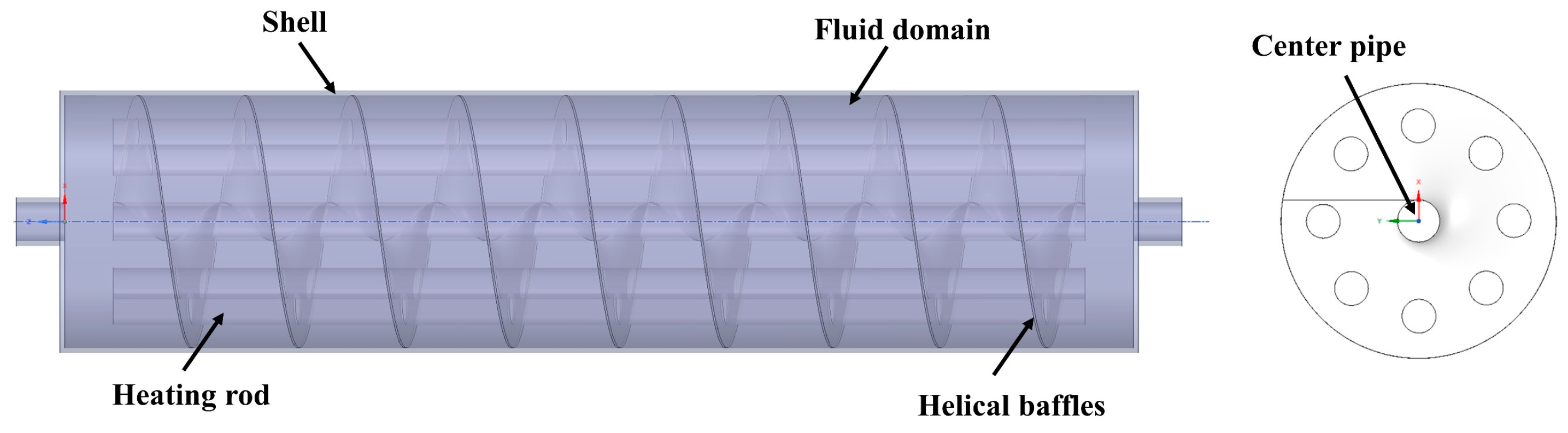
Figure 1. The segmental baffle used in Nong’an.
Applsci 14 02235 g001
Figure 2. The helical baffle used in Fuyu.
Applsci 14 02235 g002
Figure 3. Heater physical model.
Applsci 14 02235 g003
Figure 4. Temperature distribution on the surface of the heating rod.
Applsci 14 02235 g004
Figure 5. Heating rod surface temperature: (a) 160 m3/h, 4 kW; (b) 200 m3/h, 6 kW.
Applsci 14 02235 g005
Figure 6. The curve of heater outlet temperature: (a) the first stage; (b) the second stage.
Applsci 14 02235 g006
Figure 7. Maximum outlet temperature: (a) heating power; (b) inject flow rate.
Applsci 14 02235 g007
Figure 8. Pressure distribution in the heater shell.
Applsci 14 02235 g008
Figure 9. Flow rate distribution of gas in the heater.
Applsci 14 02235 g009
Figure 10. Comprehensive heat transfer performance at different working conditions.
Applsci 14 02235 g010
Table 1. Heater specific parameters.
ItemDimension (mm)
Shell inside diameter260
Shell outside diameter270
Shell length1100
Inlet and outlet nozzle diameter40
Battle length1000
Battle thickness2
Helical pitch110
Central tube outside diameter40
Effective length of heating rod1000
Heating rod outside diameter32
Number of heating rods8
Heating rod layout pattern45° rotation
Disclaimer/Publisher’s Note: The statements, opinions and data contained in all publications are solely those of the individual author(s) and contributor(s) and not of MDPI and/or the editor(s). MDPI and/or the editor(s) disclaim responsibility for any injury to people or property resulting from any ideas, methods, instructions or products referred to in the content.

