Article

Mechanism and Prevention of Main Roadway Roof Shock in Strong-Bump Coal Seam with Asymmetric Goaf

1
School of Mines, China University of Mining and Technology, Xuzhou 221116, China
2
Jiangsu Engineering Laboratory of Mine Earthquake Monitoring and Prevention, China University of Mining and Technology, Xuzhou 221116, China
*
Author to whom correspondence should be addressed.
Appl. Sci. 2024, 14(6), 2264; https://doi.org/10.3390/app14062264
Submission received: 18 January 2024 / Revised: 26 February 2024 / Accepted: 6 March 2024 / Published: 7 March 2024

Abstract

:
In response to the increasingly severe situation of main roadway shock in coal seams, with a focus on the strong-bump coal seam in main roadways under an asymmetric goaf in a certain mine, theoretical analysis, numerical simulation, and engineering practices were employed. This study investigated factors influencing main roadway roof shock damage, changes in roof stress, and characteristics of overlying strata movement. This research unveiled the mechanism and prevention of roof shock in main roadways of strong-bump coal seams in an asymmetric goaf. The research results indicate that the influencing factors of main roadway roof shock damage can be divided into two categories: “strata-support” structure strength and surrounding rock stress. For the determination of the “strata-support” structure, in the case of strong bumps in coal seam roadways influenced by the asymmetric goaf, the key factors contributing to shock damage are the side abutment pressure on the coal pillar in the goaf and the activity level of the roof strata. The distribution of roof stress in the main roadway undergoes continuous changes as district faces are sequentially mined. When the goaf area on the west side gradually increases towards the south, the roof stress in the main roadway consistently rises, and the stress increment follows a pattern of initial increase followed by a decrease. The strata structure of the main roadway roof gradually transforms from an “asymmetric T” shape to a “symmetric T” shape in the transverse profile, and with the evolution of the roof rock layer structure, the mutual feedback effect of strata activity on both sides of the roadway gradually strengthens. Affected by the asymmetric goaf, the main roadway in the district undergoes three different stages: one side of subcritical mining influence → both sides of subcritical mining influence → one side of subcritical mining and one side of critical mining influence. In addition, comprehensively considering the impact of various factors in different stages, the theoretical criteria for roof shock failure in the main roadway are determined. The formulation of an optimized position for the main roadway and a scheme for depressurization through deep-hole blasting in the roof reduce the stress level in the surrounding rock of the main roadway, effectively preventing the occurrence of roof shock in the asymmetric goaf of the coal seam main roadway.

1. Introduction

With the increasing depth of coal resource extraction and the enhancement in the production capacity of individual mines after the integration of mining resources, the number of rock burst mines has gradually increased and the coverage area has also been expanding [1,2]. In this context, rock burst accidents have occurred frequently nationwide and have become one of the most serious coal and rock dynamic disasters in coal mining production. According to statistics on various dynamic ground pressure accidents that have occurred, most of them are primarily manifested as roadway impact. In recent years, with the increasing frequency of coal seam main roadway usage, incidents of main roadway rock burst accidents have also become more frequent, for example, main roadway rock burst accidents in mines such as Cuimu, Mengcun, and Gaojiapu. Coal seam main roadways, as a critical component of the mine production system, play a crucial role; once a rock burst accident occurs, it not only results in casualties and significant economic losses but also leads to prolonged production downtime in the mine [3,4]. With the continuous development of mining technology, the frequency of coal seam main roadway usage is expected to increase further. Therefore, the prevention and control of rock burst in coal seam main roadways have gradually become a key aspect in addressing rock burst issues, and it is also an important scientific problem that urgently needs to be solved in the current coal mining industry.
Regarding the research on rock burst issues, scholars from various countries have made a series of mature achievements through continuous exploration, including strength theory, stiffness theory, dynamic static load superposition principles, and so on. At the same time, different countries have constructed corresponding systems for the prevention and control of rock burst based on their actual mining conditions [5,6,7]. A large number of scholars have conducted relevant research on the impact problem caused by underground excavation; for example, Mazaira et al. [8] introduced the impact of rock bursts in underground excavation and related prevention and control measures; Askaripour, M. et al. [9] studied the mechanism, types, and corresponding prediction methods of rock bursts in tunnel excavation; Skrzypkowski, K. et al. [10] studied the correlation between the magnitude of dynamic loads from seismic sources on roadways and their propagation distance; Farhadian, H. [11] proposed the TCR classification method through the analysis of over 200 cases; Pan, J. et al. [12] conducted a study on the rock burst mechanism considering the time-varying characteristics of coal seam main roadways, and developed a weakening and unloading plan primarily based on roof hydraulic fracturing; Wang, G. et al. [13] constructed a mechanical model for the instability and failure of roadways based on the stress distribution characteristics of coal, explaining the mechanism behind the overall instability and failure of coal pillars; Gao, M. et al. [14] proposed a fully anchored support technology by analyzing the main controlling factors of main roadway roof impact failure; Xia, Y. et al. [15] identified the mechanism of repeated impact in main roadway groups in complex structural areas through factor analysis, and formulated targeted prevention methods by mainly utilizing roof super-long-hole horizontal segmented fracturing; Liu, S. et al. [16] studied the mechanism of rock burst in the roadway region under working face mining influence, determining that preventing main roadway shock damage lies primarily in adjusting the width of coal pillars; Zheng, J. et al. [17] considered the role played by hard roofs in causing roadway impact damage and proposed a method to weaken roof bands; Smoliński, A. and Seryakov, V. M. et al. [18,19] studied the stress state of the roof and the potential stress concentration of the roof under support. The above-mentioned studies all indicate that the mechanism of rock burst in coal seam main roadways is complex and significantly influenced by geological and mining technical conditions.
In previous research on rock bursts in coal seam main roadways, there has been limited consideration of the impact of different mining conditions on both sides of the main roadway. Therefore, this thesis focuses on the mechanism and prevention methods of strong bumps in coal seam main roadways with an asymmetric goaf in a certain mine. The aim is to provide valuable insights for the prevention and control of rock burst disasters in coal seam roadways under similar mining conditions.

2. Overview of the Case Study Mining Site

2.1. Basic Situation of Main Roadway

The main roadways in the fourth district of a certain mine are arranged in the 2-1 coal seam. On the east side of the main roadway is the second district, and the main roadway is parallel to the working face in the second district. On the west side of the main roadway is the fourth district, where there are 12 longwall faces (LW) including 21405 and 21406 arranged perpendicular to the main roadway. Among them, LW21405 is the initial mining face in the fourth district. As shown in Figure 1, the main roadway group in the fourth district is designed with three main roadways: the main headgate, auxiliary main headgate, and main tailgate. Among them, the main headgate and auxiliary main headgate are newly excavated tunnels, while the main tailgate utilizes the original auxiliary headgate from LW21205. The overall structure of the 2-1 coal seam in the fourth district is simple, with an average thickness of 2.95 m, a dip angle of 3 degrees, and an average burial depth of 650 m. The main roof strata of the coal seam include the Zhiluo Formation, Anding Formation, and Zhidan Group’s sandstone strata. Within the upper 400 m above the roof, there are no exceptionally thick sandstone strata, and most sandstone strata have a thickness of less than 20 m. The interlayer between the sandstone strata is mostly composed of sandy mudstone strata. The laboratory identification indicates that the 2-1 coal seam has a strong tendency for bumps, with the roof and floor showing a weak tendency for bumps. In the main roadway area of the fourth district, various widths of chain pillars are left: the goaf of LW21205 has coal pillars of 30 m, the main tailgate and the main headgate have coal pillars of 50 m, the main headgate and the auxiliary main headgate have coal pillars of 35 m, and the auxiliary main headgate and the retreat line of the fourth-district working face have chain pillars of 360 m.
The cross-section of the main roadway is rectangular, with a design dimension of width × height = 5.4 m × 3.2 m, adopting “bolting and shotcreting with wire mesh”, with a length of 2.5 m for the bolt and 7.2 m for anchor cable support. Some roadways undergo concrete spraying, with a spraying thickness of 0.1 m on the top and around the roadway, and 0.2 m on the bottom of the roadway. The overall support strength of the main tunnels is high. Affected by the asymmetric goaf, the deformation and damage of the main roadways in the fourth district are severe. However, both the roof and sidewalls of the roadways have strong support, except for the points of impact accidents. The deformation and damage of the roadways are mainly manifested in floor damage. As shown in Figure 2, after the formation of the goaf in LW21205, the deformation and damage of the roadways are evident: the main tailgate has severe deformation and damage; in the main headgate, there are obvious floor heaving and roof fall in some areas, and the sidewall deformation is significant; the auxiliary main headgate has a small overall deformation, with localized areas showing roof and floor damage.

2.2. Micseismic Activity and Surface Subsidence

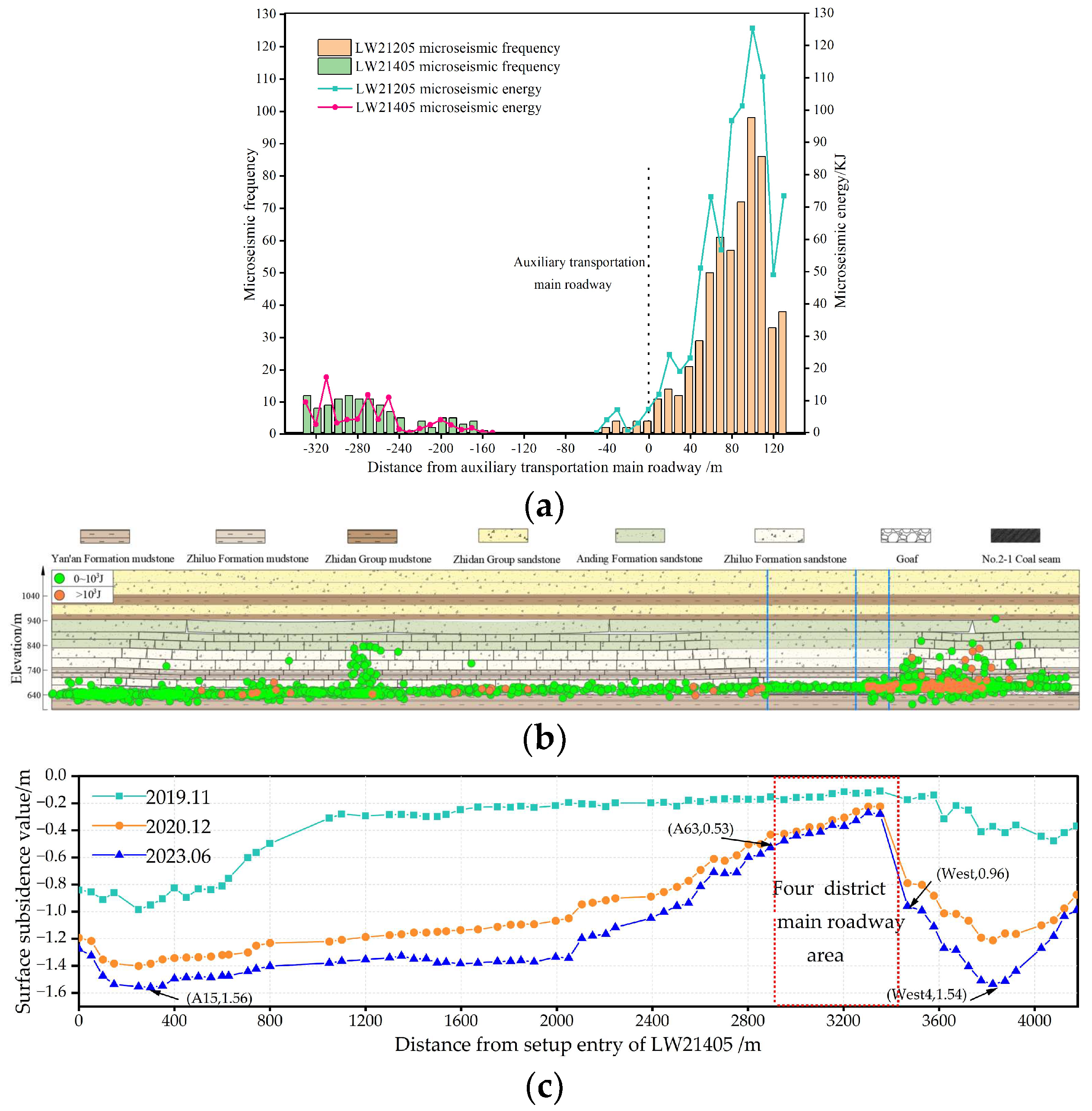
The mining of LW21205 started in April 2018. When the mining reached November 2019, LW21405 began mining. The data obtained from the SOS microseismic monitoring system and surface subsidence monitoring points during the period from the start of mining to June 2023 in the two working faces are shown in Figure 3. From Figure 3a, it can be observed that the energy and frequency of seismic activity during the mining of LW21205 are much higher than those of the LW21405 working face. The advanced impact distance of mining from LW21405 and the lateral impact distance from LW21205 are both approximately 180 m. Since the retreat line of LW21405 is protected by coal pillars with a width of 360 m in the main roadways of the fourth district, the main roadways in the fourth district are mainly affected by the seismic activity generated during the mining of LW21205, and the impact of seismic activity from LW21405 on the roadways in the fourth district is relatively small. Figure 3b,c show that during the mining of the two working faces, seismic activity is dominated by small energy events. The frequency of large energy events during the mining of LW21205 is higher than that of the LW21405 working face and the distribution characteristics of seismic activity are basically consistent with the trend of surface subsidence. After the mining of LW21205, the maximum surface subsidence occurs at the West 4 monitoring point, indicating that the segment of the coal pillar above LW21205 and LW21204 experiences damage, resulting in the connection of the goaf areas of the two working faces. In the area of the roadways in the fourth district near the goaf of LW21205, there is a significant turning point in surface subsidence, and the change in surface subsidence between two monitoring points spaced 50 m apart is greater than 0.5 m, indicating the occurrence of a long-distance “hanging roof” structure on the side of the goaf of LW21205. Compared to LW21205, the surface subsidence values after the mining of LW21405 are stable. There is a stable trend in surface subsidence near the stop line, and within a range of 200 m on both sides of the stop line, the surface subsidence values stabilize at around 0.5 m.

3. Mechanical Analysis of Roadway Roof Shock Damage

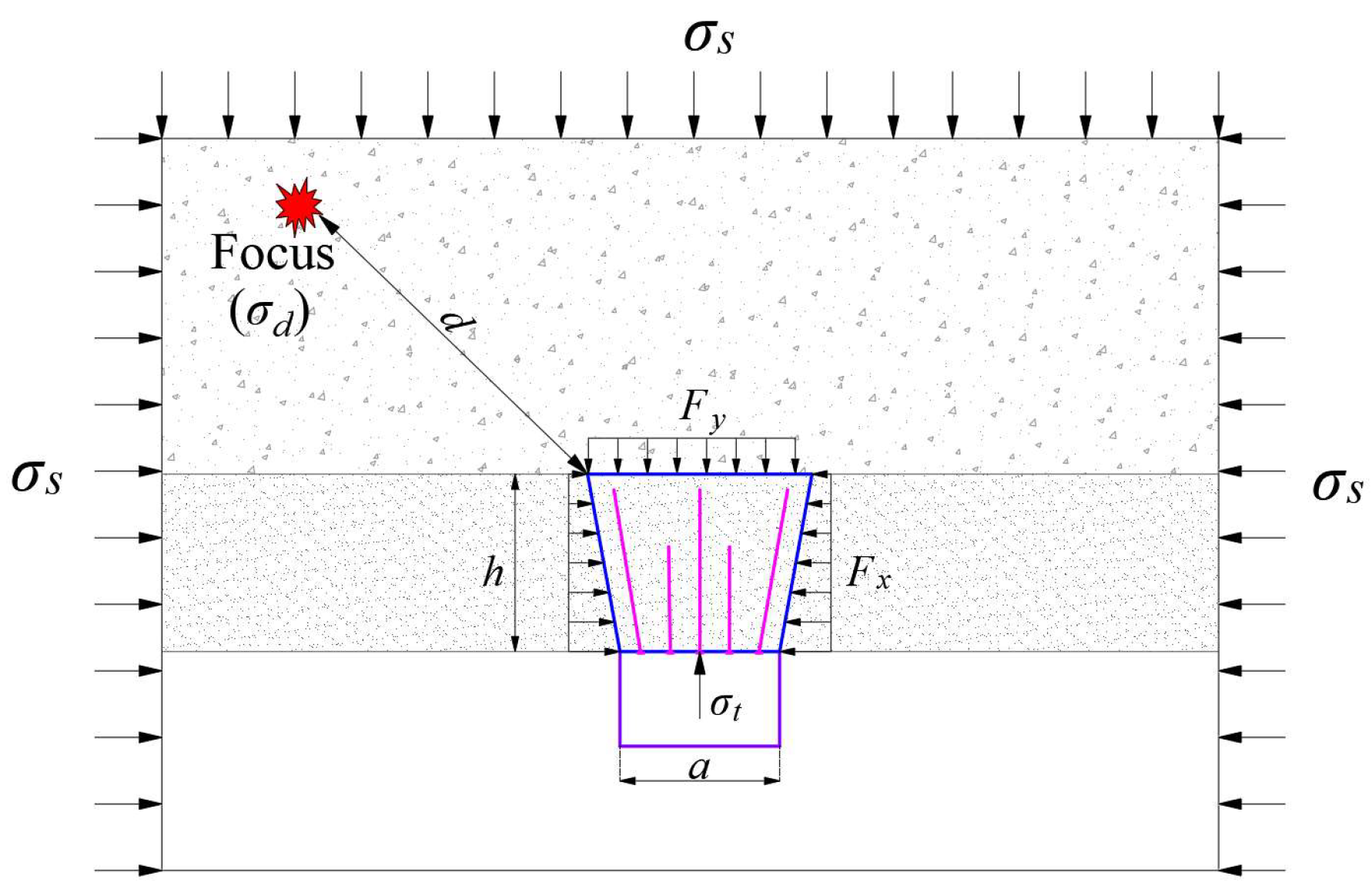
After the excavation of coal seam roadways, the overlying strata and supporting structure on the roadway’s roof will form a structure similar to a rock beam. This structure undergoes deformation and damage under the influence of surrounding rock stress. Assuming the structure is a continuous and uniform medium, the mechanical model of roadway roof shock failure is established, as shown in Figure 4. In the figure, σs represents the static load of the surrounding rock; σd is the dynamic load generated by the seismic source; σt is the supporting force of the support structure; a is the width of the roadway; h is the thickness of the structure; and d is the distance between the seismic source and the structure.
According to plate and shell theory [20,21], the buckling equation of the roadway roof structure is as follows:
K c 4 ω ( x , y ) = F x 2 ω ( x , y ) x 2 + 2 F x y 2 ω ( x , y ) x y + F y 2 ω ( x , y ) y 2
where Kc is the flexural stiffness of the structure; ω(x, y) is the deflection equation of the structure; and Fx, Fxy, and Fy are external forces acting on the structure in different directions, KN.
For the calculation of the deflection of the structure, the action of only horizontal force Fx can be considered. Therefore, Equation (1) can be simplified to
K c 4 ω ( x ) F x 2 ω ( x ) x 2 = 0
The two ends of the structure on the roadway roof can be approximated as a simply supported beam structure. Substituting the boundary conditions at x = 0 and x = a into Equation (2), the buckling equation of the structure can be calculated as
λ = 1 + A sin ( λ π x a ) ( K c λ 4 π 4 a 4 F x λ 2 π 2 a 2 ) = 0
where λ is a positive integer, λ ≥ 1.
Simplifying Equation (3), Fx can be calculated as
F x = K c λ 2 π 2 a 2
For the structure, its flexural stiffness Kc is
K c = E h 3 12 ( 1 μ 2 )
where E represents the elastic modulus of the structure in GPa, and μ is Poisson’s ratio of the structure.
In conclusion, the failure load of the structure is
σ b = F x h = λ 2 E h 2 π 2 12 a 2 ( 1 μ 2 )
The stress on the roadway roof structure can be divided into static and dynamic loads. When the combined stress of both exceeds the failure load of the structure, the roadway roof will experience shock failure, and at this point:
σ s + σ d e η d λ 2 E h 2 π 2 12 a 2 ( 1 μ 2 ) 0
where η represents the attenuation indices for the dynamic load sources propagating in the coal–rock mass.
Formula (7) shows that there are two main factors affecting the shock failure of the roadway roof. One is the strength of the structure, which includes the strength of the roof strata and the support strength. The other is the surrounding rock stress, mainly including the self-weight stress and the mining-induced stress. After the roadway is formed and supported, the critical factor for its failure will be the magnitude of the mining-induced stress.
As shown in Figure 5, for main roadways affected by an asymmetric goaf, the static load on the surrounding rock mainly comes from the changes in the goaf on both sides and the excavation of the adjacent roadway; the dynamic load comes from the overlying rock activity in the goafs on both sides. The stress curve caused by roadway excavation with chain pillars greater than 6 times the roadway radius is “double-peak” shaped, relatively stable, and has a small impact on adjacent tunnels. Therefore, the key to the shock failure of the roadway roof in the asymmetric goaf coal seam is the magnitude of the goaf abutment stress and the activity intensity of the roof strata.

4. Mechanism of Shock Failure of the Main Roadway Roof in the Coal Seam with Asymmetric Goaf

4.1. Stress Distribution Characteristics of Main Roadway

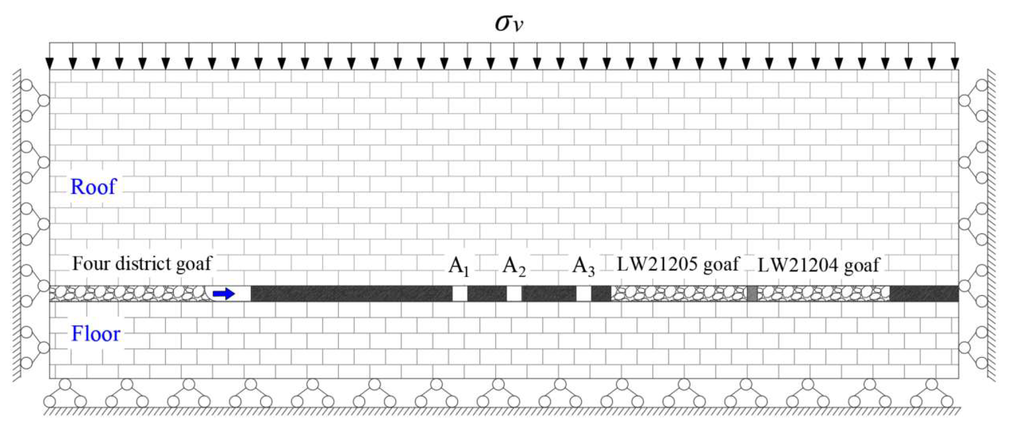
To investigate the stress distribution characteristics in the area of the coal seam main roadway in the fourth-district region influenced by an asymmetric goaf, a FLAC3D numerical model was established. The model dimensions (length × width × height) were 5000 m × 4950 m × 435 m. The model adopts the Mohr–Coulomb elastoplastic material model, where the goaf is replaced by an empty model. Horizontal constraints were applied to all sides of the model, and the bottom was subjected to both horizontal and vertical constraints, while the top was considered a free surface. Based on the measured depth of coal seam mining and in situ stress values, a vertical stress of 7.25 MPa was applied to the model’s top, and horizontal stresses of 20.55 MPa and 13.10 MPa were applied along the x and y axes, respectively. The mechanical parameters of different strata in the model were determined through on-site investigations and rock mechanics property tests, as detailed in Table 1. The simplified cross-section of the numerical model is illustrated in Figure 6.
Considering the actual conditions at the engineering site, the model first simulates the excavation of LW21204 and, subsequently, the excavation of the main headgate and auxiliary main headgate. Finally, based on the designed mining sequence for the fourth-district working faces, the model simulates the sequential excavation of working faces such as 21405 and 21406.
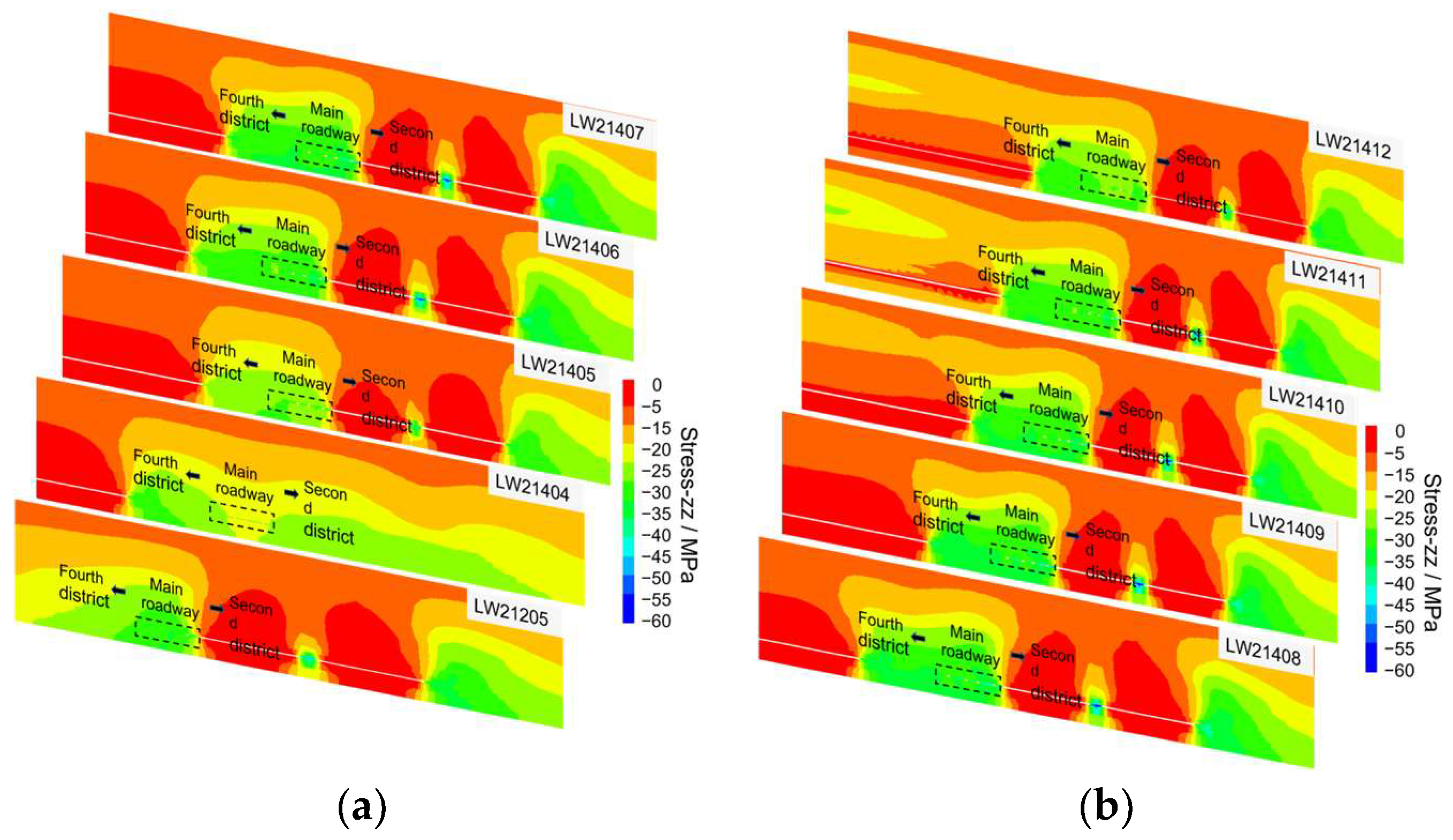
The vertical stress profile cloud map in Figure 7 illustrates the effects of sequential mining on both sides of the main roadway. As can be seen from the picture, after the mining of LW21205, the stress in the roadway area is generally within the 20~25 MPa stress contour; following the mining of LW21405, a small area of stress increase is evident in the main tailgate and main headgate regions. Post mining of LW21406, the stress-increase region expands to cover the entire main roadway area, resulting in the roadway area being mostly within the 25~35 MPa stress contour; subsequent mining activities in the 21407, 21408, and other working faces lead to a slight increase in stress in the roadway area, but the stress distribution characteristics remain unchanged. After the mining of LW21404, where the mining direction does not intersect with the goaf of LW21205, the stress in the roadway area decreases. The subsequent mining activities in 21403, 21402, and other working faces exhibit similar stress levels in the roadway area, aligning with the stress levels in the original rock stress. Therefore, the subsequent analysis will primarily focus on the mining characteristics of the 21406, 21407, and other working faces on the south side of the 21405 initial mining face.
To further refine this study and examine the stress evolution characteristics of the roadway roof after the formation of goafs on both sides, Figure 8 illustrates the vertical stress variation curves of the main roadway roof in different mining stages. From Figure 8a, it can be observed that after the mining of LW21205 on the east side of the roadway, a stress-elevated zone resembling a “double-peak” is formed on the roof of the main roadway area, the maximum peak stress is 28.06 MPa, and the maximum peak position is close to the belt transport roadway. Now, the stress distribution in the main roadway roof shows a trend of main headgate > auxiliary main headgate > main tailgate. After the excavation of the adjacent main headgate and auxiliary main headgate, the stress in the roof of the roadway area is redistributed. The stress peak transfers from the central part to both sides, resulting in a reduction in stress on the roof of the main headgate and auxiliary main headgate, with a maximum reduction of 3.20 MPa, and the stress on the roof of the main tailgate increases by 1.98 MPa. At this point, the stress distribution in the roadway roof shows a trend of main tailgate > main headgate > auxiliary main headgate.
From Figure 8b, it can be observed that after the mining of LW21405 in the fourth district, a new stress peak is formed within the 60 m range in front of the working face stop line. This results in an overall increase in stress on the roof of the main roadway area, with the magnitude of increase decreasing sequentially from the stop line towards the main tailgate. As the subsequent working faces, such as 21406 and 21407, located south of the 21405 initial mining face, are further mined, leading to an increase in the area of the west-side goaf, the stress increment in the main roadway area becomes significantly larger. After the mining of LW21406, the stress values in all three roadways exceed twice the original rock stress, indicating a sharp increase in the risk of roadway shock. In order to further quantify the stress changes in the roadway area after the mining of the fourth-district area working face, the use of the unit stress increment Δσ is employed to characterize the variation in roof stress in the main roadway. This is given by
Δ σ = ( σ p , n + 1 σ p , n )
where σp,n+1 and σp,n represent the vertical stress on the roof of roadway p during the excavation of the n and n + 1 working faces in the fourth district, MPa.
As shown in Figure 8c, the change in stress on the roof of the main roadway in the fourth-district area after the excavation of the working faces follows the trend of main tailgate > main headgate > auxiliary main headgate. When the working faces in the fourth-district area are excavated sequentially from LW21405 to both sides, the stress increment first increases and then decreases. Specifically, after the excavation of the northern side with the first mining face, the stress increment in the roadway area shows negative growth. However, after the excavation of the southern side with the first mining face, the stress increment shows growth, with LW21406 exhibiting the most significant increment at 9.19 MPa.

4.2. Structural Evolution Characteristics of Overlying Strata in Main Roadway

According to the probability integration method [22,23], the calculated maximum subsidence values for the 21205 and 21405 working faces are in the range of 1.18 to 2.80 m.
W max = q m cos θ
where q represents the subsidence factor, 0.4~0.95; m represents the coal seam thickness, 2.95 m; and θ represents the coal seam dip angle, 3°.
According to Figure 3, it can be observed that the maximum subsidence values after the extraction of the 21205 and 21405 working faces exceed 1.5 m. The maximum subsidence values meet the requirements for empirical maximum subsidence, indicating that the subsidence of the roof in this location is generally stable, the roof has come into contact with the floor, and the gangue has been re-compacted, closing the fractures in the roof space. This point is considered a support point for the rock in the goaf. On the west side of the main roadway in the fourth-district area, there is a noticeable change in surface subsidence values, and seismic activity is frequent. This suggests that the upper main bearing stratum has not been completely damaged, providing support. The other strata are structurally unstable with high activity. On the east side of the fourth-district main roadway, surface subsidence values are already less than the maximum empirical subsidence value at a distance of 400 m from the stop line, and they continue to steadily decrease towards the west, which indicates that the structure of the main bearing stratum above the stop line after the extraction of LW21405 is stable.
According to the analysis in Section 2.2, it is known that after the extraction of LW21205, LW21405, and LW21404, the goaf is connected, resulting in an increased size of the goaf to 670 m. The theory of mining subsidence [24,25] suggests that the fracturing of overlying strata and surface subsidence is related to the ratio λ of mining depth to mining size. When λ is in the range of 1.2 to 1.4, the mining area is critical mining, and surface subsidence does not increase. When λ is less than 1.2, the mining area is subcritical mining, and the development height of fracture structures in the overlying strata is approximately half the length of the short side of the goaf. Based on the mining conditions of the working faces on both sides of the main roadway in the fourth district, it is determined that the trending direction of both the 21205 and 20405 working faces on both sides of the main roadway has not reached critical mining after extraction. Therefore, after the extraction of the 21205 and 21405 working faces, the development height of fracture structures in the overlying strata on the east side of the main roadway in the fourth district is approximately 335 m, while on the west side, it is approximately 155 m.
The deformation and damage of the coal seam main roadway in the fourth district are mainly influenced by the activity of the roof strata caused by the asymmetric extraction of working faces on both sides of the main roadway. The key stratum theory [26,27] suggests that the key stratum plays a controlling role in the strata movement induced by coal seam mining, and it satisfies the following relationship:
{ q n , i = E i h i 3 j = i n γ j h j / j = i n γ j h j 3 q n , i < q n + 1 , i
{ l n = h n 2 R n , T k = 0 m n E n , k h 3 n , k E n , 0 h 3 n , 0 ( k = 0 m n h n , k γ n , k + H γ ) l n < l n + 1
where n, j, i, and k represent the stratum numbers; qn,i is the load of the nth stratum on the ith stratum; Ei and hi are the elastic modulus and thickness of the ith stratum; γj and hj are the unit weight and thickness of the jth stratum; mn is the number of strata of soft rock controlled by the nth strata of hard rock; and ln, H, and RT are the rupture distance, burial depth, and uniaxial tensile strength of the nth stratum.
According to the information on the roof strata in Section 2.1 and combined with the roof failure observations on both sides of the main roadway, it is determined that there are three subkey strata and one main key strata in the roof of the roadway area, as detailed in Table 2.
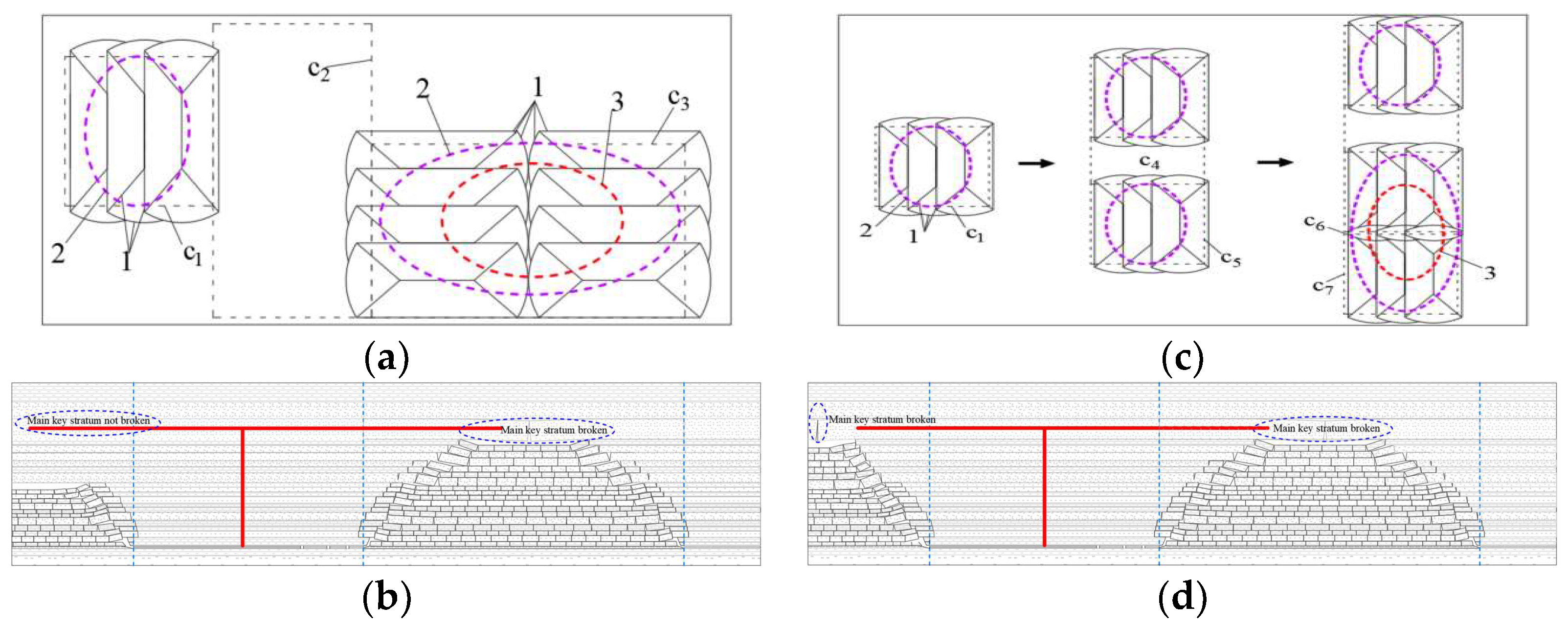
After the mining operations of the 21205 and 21405 working faces, the roof strata structure in the main roadway of the fourth district is illustrated in plan view in Figure 9a: on the 21405 goaf side, the subkey strata exhibit O-X fractures, and the higher main key strata remain intact; on the 21205 goaf side, both the subkey strata and the main key strata show O-X fractures. In the cross-sectional view depicted in Figure 9b, the main roadway roof forms an “asymmetric T” structure; on the 21405 goaf side, due to the smaller height of the fractured roof strata, the overall overlying rock structure is relatively stable, with a limited impact range of structural damage on the fourth-district main roadway. As shown in Figure 9c, this schematic diagram illustrates the variation in overlying rock structure on the western side of the fourth district. It can be observed that with the mining operations of the 21406 and 21407 working faces, the height of the fractured strata on the western side of the roadway gradually rises until the main key strata fracture. At this point, the overlying rock structure in the roadway area will evolve into a “symmetric T structure”. For the fourth-district roadway, the primary influence is the “long-arm F” structure on the goaf side. Under this structure, the lateral abutment pressure increases closer to the goaf coal body, and the vibrations within the goaf are frequent, making the fourth-district roadway prone to deformation and damage, with the main tailgate being most affected. Additionally, as the goaf area of the fourth district increases, the height of strata fractures rises, leading to reduced stability and increased energy released in the rock strata structure. This enhances the “mutual feedback” effect of rock strata activity on both sides of the main roadway, increasing the intensity and frequency of dynamic disturbances experienced by the roadway and resulting in a higher risk of main roadway shock.

4.3. Shock Failure Mechanism of Main Roadway Roof

In summary, the stress distribution and overlying rock structure of the coal seam main roadway in the fourth district are influenced by the asymmetric goaf, undergoing three distinct stages: one side of subcritical mining influence → both sides of subcritical mining influence → one side of subcritical mining and one side of critical mining influence. Throughout this process, factors such as original rock stress, goaf abutment pressure, and mining disturbances all play a role in impacting the main roadway’s susceptibility to shock failure. By considering various factors and integrating the theoretical analysis results from Section 2, the mechanism of shock failure in the coal seam main roadway with an asymmetric goaf is analyzed and determined.
(1)
Analysis of static load on the main roadway. Numerical simulation results indicate that, apart from the foundational static load provided by the original rock stress σv, the main static load increments in the main roadway’s surrounding rock come from the stress increments ∆σs1 and ∆σs2 caused by abutment pressure in the goaf on both sides of the roadway. In addition, the excavation of adjacent main roadways leads to changes in the stress distribution of the main roadway’s surrounding rock, resulting in a change for a single main roadway, denoted as ∆σs3.
(2)
Analysis of dynamic load on the main roadway. The seismic activity patterns on both sides of the main roadway and the characteristics of overlying rock structure changes indicate that the primary source of dynamic load on the main roadway comes from disturbances caused by the excavation of working faces on both sides, disturbances from adjacent main roadway excavation, and dynamic loads generated by damage in the overlying strata, denoted as ∆σd1, ∆σd2, and ∆σd3.
(3)
Analysis of “mutual feedback” effects in the goafs on both sides of the main roadway. As the goaf area increases on the west side of the main roadway, the height of fractures in the overlying strata and the overall strata activity increase. The static load generated by the cantilever on the goaf side and the dynamic load generated by rock fractures both increase. With the increased load, the corresponding influence distance also increases. When the influence range extends to the active range of strata in the goaf on the east side of the main roadway, there is mutual interaction between the strata structures on both sides of the roadway, resulting in respective static and dynamic loads denoted as σ s and σ d .
Therefore, under the influence of asymmetric goafs, the stress on the surrounding rock of the coal seam main roadway is given by
σ s = σ v + Δ σ s + σ s + Δ σ d + σ d
Δ σ d = Δ σ d 1 e η 1 d 1 + Δ σ d 2 e η 2 d 2 + Δ σ d 3 e η 3 d 3
Δ σ s = Δ σ s 1 + Δ σ s 2 + Δ σ s 3
where η1, η2, and η3 are the attenuation indices for the three types of dynamic load sources propagating in the coal–rock mass, and d1, d2, and d3 are the distances of the three dynamic load sources from the coal seam roadway.
By substituting Formula (12) into Formula (7), the criterion for the occurrence of shock failure in an asymmetric coal seam main roadway roof is obtained:
σ v + Δ σ s + σ s + Δ σ d + σ d λ 2 E h 2 π 2 12 a 2 ( 1 μ 2 ) 0

5. Method and Effect Analysis of Rock Burst Prevention and Control

5.1. Prevention and Control Method

As analyzed earlier, the key to preventing the shock damage of the main roadway lies in reducing the abutment pressure on both sides and minimizing the mutual feedback effect of the roof strata in the goaf on both sides of the main roadway, as well as increasing the anti-failure capacity of the rock-support structure. Based on this, the following targeted preventive measures are formulated.

5.1.1. Location Optimization of Main Tailgate

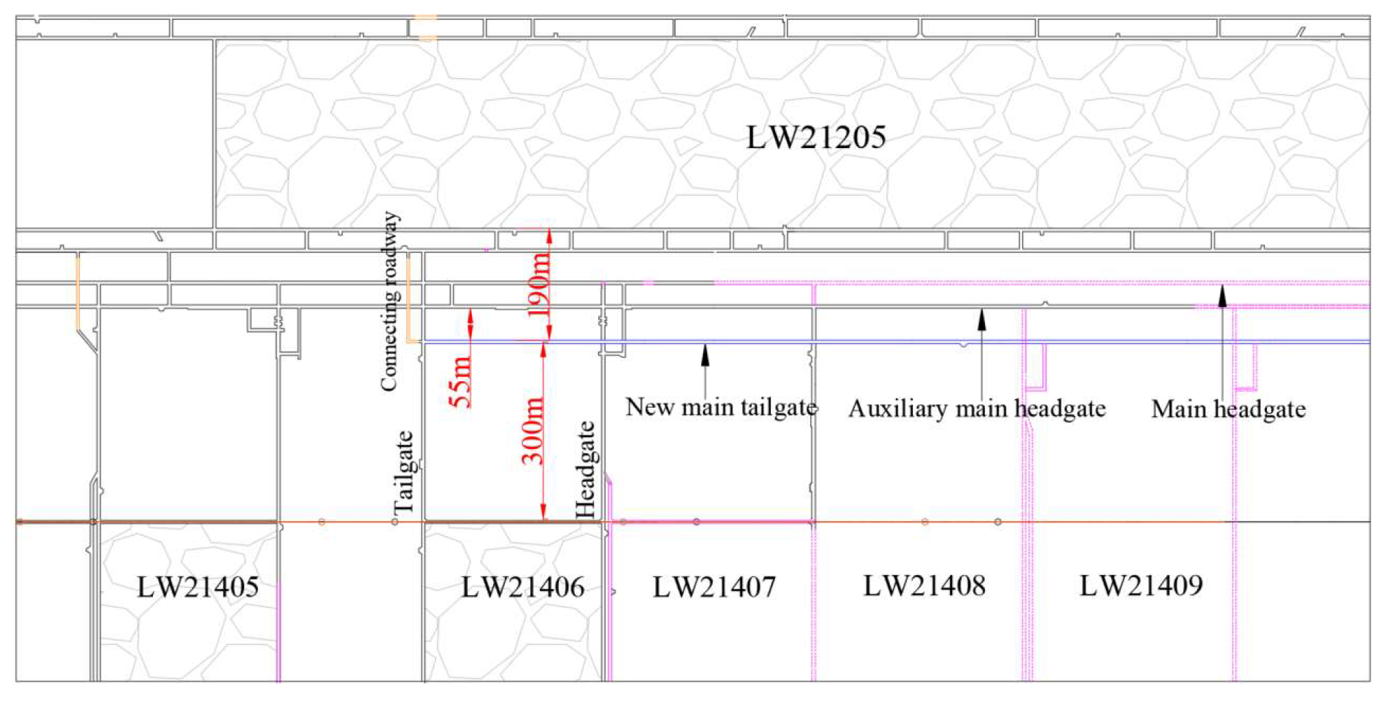
According to the analysis of the actual site conditions, it is evident that the main tailgate suffers severe damage and deformation after the mining of the 21205 and 21405 working faces. Furthermore, with the increasing size of the goaf on the west side of the main roadway, the impact of mining on the main tailgate will further increase. Considering these factors, it is determined that the main tailgate is no longer suitable for use and requires a redesign of the excavation. The auxiliary main headgate on both sides has a larger width of chain pillars, with overall deformation and damage being less apparent, indicating higher safety. Therefore, it is preliminarily decided to design the new main tailgate on the west side of the auxiliary main headgate. Based on the results of numerical simulations and analysis of mining-induced seismic activity, it is found that the influence distance of the 21405 and 21205 working faces is both 180 m. As the size of the goaf on the west side of the main roadway increases, the influence range on the west side will also expand. Since the goaf on the 21205 side is already formed and will not change significantly, its influence range will remain stable. Therefore, the new main tailgate is designed at a position beyond 180 m from the 21205 goaf. Consideration is given to the “feedback” effect of the two-sided goaf and the addition of a safety distance of 10 m on top of the 180 m. Further consideration of the interaction between adjacent roadways is essential to avoid the cumulative stress caused by the two roadways. Therefore, it is necessary to design the distance between the new main tailgate and the auxiliary main headgate to be greater than 6 times the width of the roadway. In summary, the determined design position for the new main tailgate is 190 m from the 21205 goaf and 300 m from the stop line of the fourth-district working faces, as shown in Figure 10.

5.1.2. Roof Breaking by Deep-Hole Blasting

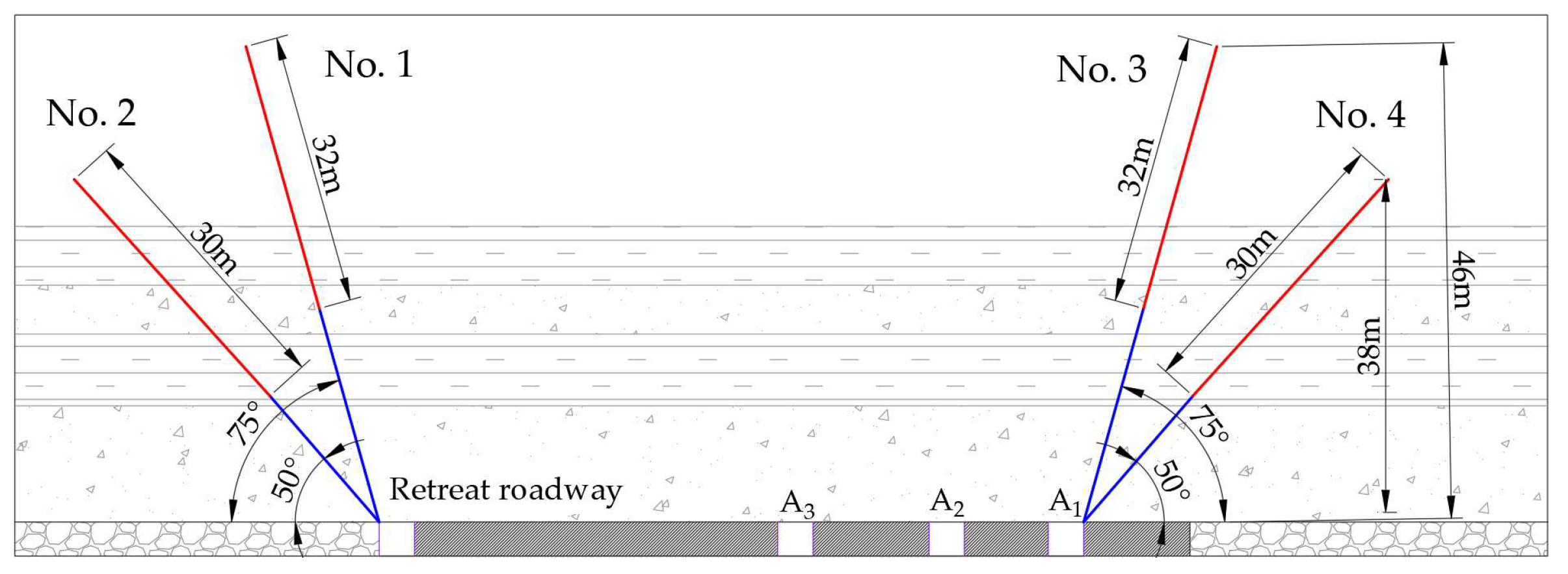
The previous analysis indicates that the surrounding rock stress in the roadway mainly comes from the abutment pressure of the coal pillar on the goaf side. According to the “three-zone theory” of overlying strata, the abutment pressure of the coal pillar can be considered as half of the self-weight stress of the overlying strata. The magnitude of the self-weight stress of the overlying strata above the coal pillar depends on the length of the “cantilever structure” of the roof above the coal pillar. Therefore, reducing the length of the roof cantilever can effectively reduce the influence of mining on the coal seam roadway. The analysis results of the key strata and microseismic activity show that there are four hard sandstone strata above the roadway, among which the medium sandstone strata, 32.28 m above the coal seam with a thickness of 22.78 m, are the dense strata of seismic activity during the mining process. Therefore, it is determined that roof breaking blasting is mainly targeted at these strata, and the construction site is the retreat channel of the fourth-district working face and the original main tailgate. As shown in Figure 11, two blasting holes are designed in each group of the roof, with a spacing of 15 m between each group in the fourth-district retreat channel and 30 m in the original main tailgate. The red line in the figure represents the length of the charge, the blue line represents the length of the sealing hole, and the other blasting parameters are shown in Table 3.

5.2. Prevention and Control Effect Inspection

Based on the distribution of seismic energy and frequency during the post-mining period of the fourth-district working faces as shown in Figure 12, it can be observed that the monthly average seismic frequency for LW21405 at the end of mining is 118 times, with an average energy of 1.65 × 10³ J. The monthly average seismic frequency for LW21406 at the end of mining is 10 times, with an average energy of 16.6 × 10³ J. Overall, the daily average frequency for both working faces during the post-mining period is below 5, and the daily average energy is less than 0.6 × 10³ J, indicating effective overall control measures. LW21406, after the explosive top coal breaking compared to LW21405, shows a significant decrease in seismic frequency, a substantial increase in individual seismic energy, and a rise in the seismic source height. This suggests that after the top coal breaking, the activity of the roof strata extends towards the higher section, enhancing the accumulation and release of energy in the upper section of the roof.
After the subsequent mining of the 21407, 21408, and other working faces, the goaf area in the fourth district will further increase. Consequently, the cantilever structure on the coal pillar side of the goaf area will gradually extend towards higher positions. At this point, conventional deep-hole blasting for the top coal breaking will no longer be effective in ensuring the treatment of the higher section of the roof. Therefore, for the top coal breaking and weakening treatment of the hard roof at medium and high levels, it is necessary to employ underground directional long-hole hydraulic fracturing or surface horizontal well hydraulic fracturing technology.

6. Conclusions

(1)
The results of mechanical analysis suggest that the factors influencing the roof shock failure of the main roadway primarily fall into two categories: the strength of the strata-support structure and the horizontal stress in the surrounding rock. For the already-formed main roadway under the influence of an asymmetric goaf, the key to roof shock failure lies in the magnitude of the goaf abutment pressure and the strength of the roof strata activity.
(2)
Numerical simulation results demonstrate that with the sequential mining of the district faces, the distribution of roof stress in the main roadway gradually changes from the main headgate > auxiliary main headgate > main tailgate to the main tailgate > main headgate > auxiliary main headgate. Additionally, as the area of the goaf on the west side gradually increases towards the south, the peak stress on the main roadway roof continues to increase, and the stress increment shows a trend of increasing first and then decreasing.
(3)
Based on surface subsidence data and analysis of mining-induced subsidence theory, the structural evolution of the roof strata in the main roadway changes from an “asymmetric T” shape to a gradually “symmetric T” shape in the transverse profile. With the evolution of the roof strata structure, the mutual feedback effect of strata activity on both sides of the roadway gradually strengthens.
(4)
The distribution of roof stress and strata structure in the coal seam main roadway of the fourth district is influenced by the asymmetric goaf, experiencing three different stages: one side of subcritical mining influence → both sides of subcritical mining influence → one side of subcritical mining and one side of critical mining influence. Considering the impact of various factors in different stages, the theoretical criteria for roof shock failure in the main roadway are determined.
(5)
Based on the coal seam main roadway roof shock mechanism with the asymmetric goaf, a load reduction and impact reduction plan mainly composed of roof blasting has been developed. The on-site practice has shown good results, providing guidance and reference for the prevention and control of rock burst under similar conditions.

Author Contributions

W.Z. conceived, designed, and analyzed the test results; A.C. provided ideas and modification suggestions; N.Z. wrote the manuscript; G.L. (Guowei Lv) used software; G.L. (Geng Li) performed project administration; Y.P. and Q.G. participated in the processing of some data. All authors have made equal contributions to the revision of the paper. All authors have read and agreed to the published version of the manuscript.

Funding

This research was funded by the National Natural Science Foundation of China (Nos. 52274098, U21A20110), National Key Research and Development Program (No. 2022YFC3004603) and Jiangsu Province International Collaboration Program-Key National Industrial Technology Research and Development Cooperation Projects (No. BZ2023050).

Institutional Review Board Statement

Not applicable.

Informed Consent Statement

Not applicable.

Data Availability Statement

The raw data supporting the conclusions of this article will be made available by the authors on request.

Conflicts of Interest

The authors declare no conflicts of interest.

References

  1. Pan, Y.S.; Song, Y.M.; Liu, J. Pattern, change and new situation of coal mine rockburst prevention and control in China. Chin. J. Rock Mech. Eng. 2023, 42, 2081–2095. [Google Scholar]
  2. Cao, A.Y.; Dou, L.M.; Bai, X.Q.; Liu, Y.Q.; Yang, K.; Li, J.Z.; Wang, C.B. State-of-the-art occurrence mechanism and hazard control of mining tremors and their challenges in Chinese coal mines. J. China Coal Soc. 2023, 48, 1894–1918. [Google Scholar]
  3. Pan, J.F.; Liu, S.H.; Xia, Y.X.; Gao, J.M. Impact failure characteristics and support methods of roadway in largely-inclined broken coal seams. J. Min. Saf. Eng. 2021, 38, 946–953. [Google Scholar]
  4. Feng, L.F.; Dou, L.M.; Wang, H.; Wang, X.D.; Xu, G.G.; Zhang, Q.; Jiao, B. Mechanism of rockburst in dense roadway area near the goaf of fully-mechanized large pillars. Min. Saf. Eng. 2021, 38, 1100–1110+1121. [Google Scholar]
  5. Dou, L.M.; Tian, X.Y.; Cao, A.Y.; Gong, S.Y.; He, H.; He, J.; Cai, W.; Li, X.W. Present situation and problems of coal mine rock burst prevention and control in China. J. China Coal Soc. 2022, 47, 152–171. [Google Scholar]
  6. Wu, S.K.; Zhang, J.W.; Song, Z.X.; Fan, W.B.; Zhang, Y.; Dong, X.K.; Zhang, Y.J.; Kan, B.H.; Cheng, Z.S.; Zhang, J.T.; et al. Review of the development status of rock burst disaster prevention system in China. J. Cent. South Univ. 2023, 30, 3763–3789. [Google Scholar] [CrossRef]
  7. Pan, J.F.; Liu, S.H.; Gao, J.M.; Song, X.K.; Xia, Y.X.; Wang, Q. Prevention theory and technology of rock burst with distinguish dynamic and static load sources in deep mine roadway. J. China Coal Soc. 2020, 45, 1607–1613. [Google Scholar]
  8. Mazaira, A.; Konicek, P. Intense rockburst impacts in deep underground construction and their prevention. Can. Geotech. J. 2015, 52, 1426–1439. [Google Scholar] [CrossRef]
  9. Askaripour, M.; Saeidi, A.; Rouleau, A.; Mercier-Langevin, P. Rockburst in underground excavations: A review of mechanism, classification, and prediction methods. Undergr. Space 2022, 7, 577–607. [Google Scholar] [CrossRef]
  10. Skrzypkowski, K.; Zagórski, K.; Zagórska, A.; Apel, D.B.; Wang, J.; Xu, H.; Guo, L. Choice of the Arch Yielding Support for the Preparatory Roadway Located near the Fault. Energies 2022, 15, 3774. [Google Scholar] [CrossRef]
  11. Farhadian, H. A new empirical chart for rockburst analysis in tunnelling: Tunnel rockburst classification (TRC). Int. J. Min. Sci. Technol. 2021, 31, 603–610. [Google Scholar] [CrossRef]
  12. Pan, J.F.; Yan, Y.D.; Ma, X.H.; Xie, F.; Ma, W.T.; Lv, D.Z.; Song, X.D.; Feng, M.H. Mechanism and prevention pf rock burst in coal seam roadway group considering time-varying characteristics. J. China Coal Soc. 2022, 47, 3384–3395. [Google Scholar]
  13. Wang, G.A.; Zhu, S.T.; Jiang, F.X.; Li, S.D.; Liu, J.H.; Zhou, T.; Ning, Y.Z.; Li, H.; Kong, Z. Creep instability rock burst mechanism and prevention technology of isolated coal mass in roadways of high-stress thick coal seam. Chin. J. Geotech. Eng. 2022, 44, 1689–1698+9. [Google Scholar]
  14. Gao, M.S.; Xu, D.; Wang, H.C.; Yu, X.; Liu, R.F. Shock failure mechanism of roadway in extra thick coal seam and full anchor cable support technology. J. China Coal Soc. 2023, 48, 1943–1956. [Google Scholar]
  15. Xia, Y.X.; Pan, J.F.; Xie, F.; Feng, M.H.; Liu, S.H.; Liu, C. Disaster mechanism and control technology of large roadway group with repeated impact in extra-thick coal seam. Chin. J. Rock Mech. Eng. 2022, 41, 2199–2209. [Google Scholar]
  16. Liu, S.H.; Pan, J.F.; Xi, G.J.; Jiao, B.; Xia, Y.X.; Shi, X.X. Study on the mechanism and prevention and control of roadway impact in strong impact coal seam under the influence of mining. J. China Coal Soc. 2023, 1–9. [Google Scholar]
  17. Zheng, J.W.; Ju, W.J.; Lv, D.Z.; Sun, X.D.; Jiang, P.F.; Li, H.T.; Fu, Y.K.; Du, T.T.; Liu, B. Mechanism and practice of roof strip weakening method for preventing rockburst in central roadway. J. China Coal Soc. 2023, 48, 1169–1178. [Google Scholar]
  18. Smoliński, A.; Malashkevych, D.; Petlovanyi, M.; Rysbekov, K.; Lozynskyi, V.; Sai, K. Research into Impact of Leaving Waste Rocks in the Mined-Out Space on the Geomechanical State of the Rock Mass Surrounding the Longwall Face. Energies 2022, 15, 9522. [Google Scholar] [CrossRef]
  19. Seryakov, V.M.; Krasnovsky, A.A. Stress State of Support System in Temporary Roadway in Unstable Rock Mass. J. Min. Sci. 2022, 58, 911–919. [Google Scholar] [CrossRef]
  20. Cui, F.; Jia, C.; Lai, X.P.; Cheng, J.Q. Study on the evolution characteristics and stability of overburden structure in upward mining of short distance coal seams with strong burst tendency. Chin. J. Rock Mech. Eng. 2020, 39, 507–521. [Google Scholar]
  21. Ding, Z.W.; Li, X.F.; Zhang, J.; Zhao, Z.Q.; Xue, B.; Di, G.Q.; Shen, S.K. A theoretical analysis of unsupported roof plate and shell in excavation roadway and numerical calculation and verification of transcendental function. J. Min. Saf. Eng. 2021, 38, 507–517. [Google Scholar]
  22. Li, Y.P.; Zhao, S.K.; Li, Y.; Wang, Y.; Qing, K.; Sun, D.Q.; Li, Y.Z.; Zhao, Y. Prediction on weighting classification of fully-mechanized caving mining under extremely thick coal seam. J. China Coal Soc. 2021, 46, 38–48. [Google Scholar]
  23. Liu, H.; Li, Y.; Su, L.J.; Zhu, X.J.; Zhang, P.F.; Yao, M.M.; Wang, J.Z.; Wang, Q.W.; Si, G.Y. Surface deformation law of mining under thick loose layer and thin bedrock: Taking the southern Shandong Mining Area as an example. Coal Sci. Technol. 2023, 51, 11–23. [Google Scholar]
  24. Ren, X.Y.; Hao, B.Y.; He, F.S.; Wang, H.W.; Miao, Q.W. Research on staggered distance of upper and lower coal seam cooperative mining face based on subsidence prediction. Coal Sci. Technol. 2022, 50, 102–108. [Google Scholar]
  25. Peng, S.L.; Cheng, H.; Yao, Z.S.; Rong, C.X.; Cai, H.B.; Zhang, L.L. Study on prediction and characteristics of surface subsidence in mining when the bottom aquifer of thick loose layer directly covers thin bedrock. J. China Coal Soc. 2022, 47, 4417–4430. [Google Scholar]
  26. Xue, C.C.; Cao, A.Y.; Niu, F.W.; Wang, X.Y.; Shen, Z.P.; Tang, K. Mechanism and prevention of rock burst in deep irregular isolated coal pillar. Min. Saf. Eng. 2021, 38, 479–486. [Google Scholar]
  27. Guo, W.H.; Cao, A.Y.; Wen, Y.Y.; Xue, C.C.; Lv, G.W.; Zhao, Q. Mechanism of rockburst in stopes with typical thick roof and wide coal pillars in Ordos mining area. Min. Saf. Eng. 2021, 38, 720–729. [Google Scholar]
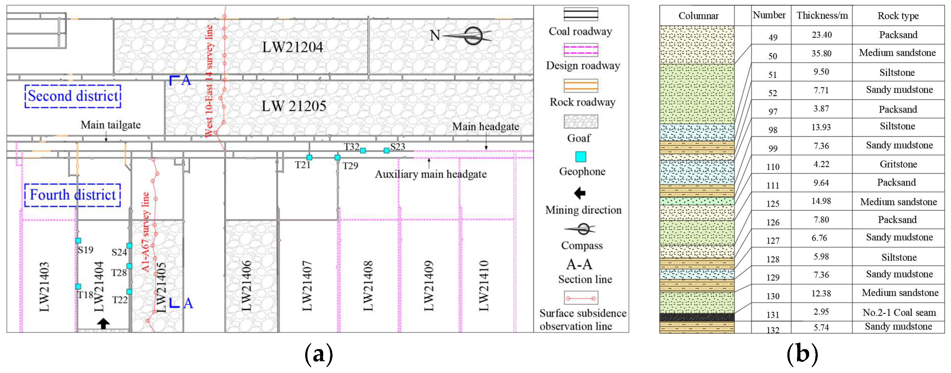
Figure 1. Basic situation of main roadway in four districts. (a) Layout of the main roadway. (b) Integrated column chart of the main roadway.
Applsci 14 02264 g001
Figure 2. Deformation and failure of main roadway. (a) Main tailgate. (b) Main headgate. (c) Auxiliary main headgate.
Applsci 14 02264 g002
Figure 3. Map of surface subsidence and microseismic distribution during stopping in 21205 and 21405 faces. (a) Distribution of microseismic activity on both sides of the main roadway after the mining of LW21405. (b) Microseismic distribution profile for working faces 21205 and 21405. (c) Surface settlement curves for working faces 21205 and 21405.
Applsci 14 02264 g003
Figure 4. Mechanical model of shock failure of main roadway.
Applsci 14 02264 g004
Figure 5. Schematic diagram of mining-induced stress in main roadway of coal seam. (a) Excavation of adjacent roadway. (b) Mining on both sides of the face.
Applsci 14 02264 g005
Figure 6. Simplified diagram of numerical model section.
Applsci 14 02264 g006
Figure 7. Cloud map of vertical stress profile on both sides of main roadway at different stop times. (a) LW21205~LW21407. (b) LW21408~LW21412.
Applsci 14 02264 g007
Figure 8. Variation curve of roof stress in main roadway area in different mining stages. (a) Stress change curve of main roadway roof before stopping in the working face of the fourth district. (b) Stress change curve of main roadway roof after stopping in the working face of the fourth district. (c) Stress increment curve.
Applsci 14 02264 g008
Figure 9. Schematic diagram of spatial structure evolution of overlying strata. (a) 21405 face after mining overburden structure plane diagram. (b) Schematic diagram of asymmetric T structure. (c) Structural change plane diagram of overlying rock on the west side of main roadway. (d) Schematic diagram of symmetrical T structure. 1—Fracture line of lower subkey strata; 2—fracture line of upper subkey strata; 3—main key strata fracture line; c1—LW21405 goaf; c2—main roadway area of fourth district; c3—21205, 21204 working face goaf; c4—21405, 21406 working face chain pillar; c5—LW21406 goaf; c6—21406, 21407 working face chain pillar; c7—LW21407 goaf.
Applsci 14 02264 g009
Figure 10. Layout diagram of the new main tailgate.
Applsci 14 02264 g010
Figure 11. Roof blasting diagram of deep-hole roof breaking.
Applsci 14 02264 g011
Figure 12. Histogram of energy and frequency of microseismic activity during final mining of the working face in fourth district.
Applsci 14 02264 g012
Table 1. Mechanical parameters of coal and rock.
LithologyDensity (kg/m3)Bulk (GPa)Shear (GPa)Cohesion (MPa)Friction (°)
Coal15404.121.478.6036
Packsand22501.443.3513.035
Sandy mudstone24501.553.828.036
Medium sandstone27002.501.801.7038
Table 2. Information of key strata in main roadway area.
Strata TypeThickness (m)Vertical Distance to Coal Seam (m)Key Strata Class
medium sandstone12.380.00subkey strata one
Sandstone group22.7832.28subkey strata two
Sandstone group17.80129.30subkey strata three
medium sandstone35.80305.62main key strata
Table 3. Roof blasting parameters of deep-hole breaking.
NumberAperture
(mm)
Depth
(m)
Charge Length (m)Explosive Charge (kg)Dip Angle (°)
17560329675
27550309050
37560329675
47550309050
Disclaimer/Publisher’s Note: The statements, opinions and data contained in all publications are solely those of the individual author(s) and contributor(s) and not of MDPI and/or the editor(s). MDPI and/or the editor(s) disclaim responsibility for any injury to people or property resulting from any ideas, methods, instructions or products referred to in the content.