Article

Stability Analysis of GNSS Stations Affected by Samos Earthquake

Department of Geomatic Engineering, Yıldız Technical University, 34220 Istanbul, Turkey
Appl. Sci. 2024, 14(6), 2301; https://doi.org/10.3390/app14062301
Submission received: 29 January 2024 / Revised: 29 February 2024 / Accepted: 1 March 2024 / Published: 9 March 2024
(This article belongs to the Special Issue Advances in Geosciences: Techniques, Applications, and Challenges)

Abstract

:
An earthquake cycle can cause meters of displacement on the surface and at Global Navigation Satellite System (GNSS) stations. This study focuses on the identification of GNSS stations that have significant displacement because of a Mw 7.0 earthquake near Samos Island on 30 October 2020. The S-transformation method is used to examine 3D, 2D and 1D coordinate systems along with threshold and statistical test approaches. The highest coseismic offset among the 21 GNSS stations is displayed by SAMO, and CESM, MNTS, IZMI and IKAR also experience significant displacement. Significantly displaced stations are successfully identified in both 3D and 2D analyses. In the up component, SAMO is the only unstable station. The coordinate S-transformation method can be used in detecting unstable points in a GNSS network and provide valuable information about the effects of an earthquake on GNSS stations.

1. Introduction

Stability analysis has a crucial role in deformation surveys for being sure of reliable and accurate measurements. In the context of GNSS deformation, monitoring stations measure the coordinates of stations on the Earth’s surface with high accuracy. These stations are typically established at man-made structures or engineering projects as well as regions prone to seismic activities. Repeatability measurements involve the repeated measurement of the same GNSS station over multiple epochs to detect any changes or deformation in the monitored station or area [1,2]. Reliable points away from deformation are needed to determine the deformation that occurs in an absolute measuring network [3,4]. Reliable points or datum points should be selected delicately to conduct an analysis of deformation. These reference points are chosen to be fixed in deformation analysis. These points serve as stable references to detect changes in the monitoring area with repeated measurements; therefore, the stabilization of reference points directly affects the results [5,6]. However, if a reference point is unstable or experiences deformation itself, utilizing this point as a reference can lead to distorted results. This will bias the results so that actual deformation cannot be detected. As a consequence, the selection of stable reference points is of importance to ensure the integrity and validity of deformation analysis. Therefore, reference points should be checked first, and any unstable points should be excluded.
To determine single-point displacement, different approaches have been tried in the literature, such as the Gauss–Markov method, the implicit hypothesis method, robust estimation methods [7], the similarity transformation (S-transformation) method [8] and Msplit estimation [9,10,11]. Besides this, Aydin [12] studied the power of the global test in deformation analysis, Jafari [13] used a Bayesian approach in stability analysis of monitoring networks and Zienkiewicz [14] used squared Msplit estimation to identify unstable reference points. Among these research methods, S-transformation is a widely used approach for researchers and engineers because of the simplicity and independence of datum points.
Lim et al. [15] worked on a monitoring network comprising seven stations, with four IGS stations serving as reference points and three local CORS (Continuously Operating Reference Stations) from ISKANDARnet as test objects. They tested reference stations with iterative weighted similarity transformation (IWST) and subsequent deformation analysis using S-transformation, and concluded that no significant movements exceeding the threshold were observed at the reference stations.
Guo et al. [16] developed the “threshold approach” and “statistical test approach” based on a model of coordinate S-transformation to evaluate the stability of datum points in a first-order GNSS deformation monitoring network. The goal of the research is to assess the effectiveness and advantages of applied approaches in confirming the stability of the reference stations. The proposed method has the advantage of simplicity of calculation, and the results are insensitive to the choice of datum points. Furthermore, it ensures the unity of the reference framework and reference epoch; in other words, the proposed method is independent of the specific reference point or the time at which the measurements are taken.
Even-Tzur [17] suggested an algorithm based on sensitivity analysis of a network in the north of Israel, where the method is investigated against the Simple Transform Fault and the Locked Fault models. This shows that sensitivity analyses can be made not only on human-made objects but also on earthquake-related studies. In a tectonic sense, interseismic, coseismic and postseismic displacements on the crust alter due to strain accumulation on a fault or the magnitude of an earthquake. Active faults in Turkey can generate Mw ≥ 7 earthquakes [18,19]. The North Anatolian Fault (NAF), East Anatolian Fault (EAF), Ölüdeniz Fault, and Cyprus and Hellenic arcs are the main active faults in Turkey [20]. North–south extension due to the subduction zone in the Hellenic Arc causes Aegean fault systems to fail, like the north-dipping E–W trending fault of the Samos earthquake, which happened on 30 October 2020 [21,22]. The Mw 7.0 earthquake that happened offshore Samos Island (Greece) hit the eastern Aegean Sea and the vicinity, especially Izmir city (Turkey), and caused loss of lives and a lot of damage. Furthermore, this devastating normal-faulting earthquake led to landslides, tsunamis and surface displacement.
Characteristics of the Samos earthquake were analyzed by researchers using seismic data [23,24], a combination of InSAR and GNSS [25] and joint seismological and geodetic data [21,26,27,28,29,30]. Papers that include coseismic surface deformations derived from GNSS data generally used continuous stations [21,25,26,27,28]. Several research papers contain both survey and continuous GNSS data [29,30]. Here, I only used continuously operating reference stations to calculate coseismic deformation, and the result is compatible with the literature.
In this paper, a network of continuous stations located approximately 200 km around the earthquake epicenter was processed, and the stations that have significant coseismic offsets were identified with ordinary least squares (LS) S-transformation, also called the “Helmert-transformation” [7]. There is no need to perform a global test before S-transformation here to see if the network has undergone deformation [3] because an earthquake with a magnitude of Mw 7.0 is enough to slip the Earth’s surface by meters. Therefore, S-transformation is used with two approaches, the statistical test approach and the threshold approach, to identify unstable continuous GNSS stations. In this paper, I used the method that was developed by Guo et al. [16] to detect GNSS stations that have significant coordinate deformation in an earthquake’s vicinity.

2. Materials and Methods

2.1. S-Transformation

Conversion of a three-dimensional coordinate system into another reference frame or coordinate system acquires seven parameters: three parameters for the translation or shift of the origin between two coordinate systems for each axis, three parameters for the rotation of one coordinate system into the other around each axis and a scale factor for any scale differences between these systems. The S-transformation model for transforming 3D cartesian coordinates with seven parameters in matrix format is carried out using the following formula:
X Y Z = t x t y t z + 1 + k 1 E z E y E z 1 E x E y E x 1 X Y Z
where t x ,     t y   a n d   t z are shift parameters; E x ,   E y   a n d   E z are rotation parameters; and k is the scale factor. The first thing to do is to estimate these parameters using two measurement cartesian coordinates ( X ,   Y ,   Z and X ,   Y ,   Z ). If the number of common stations is more than three, LS adjustment can be used for estimating seven parameters [16].
The least squares method for this transformation in matrix form is represented by Equations (2) and (3):
l x l y l z + v x v y v z = 1 0 0 0 Z Y X 0 1 0 Z 0 X Y 0 0 1 Y X 0 Z t x t y t z E x E y E z k
as l + v = Ax
l x l y l z = X X Y Y Z Z
where v ^ ( n   ×   1 ) is the residual vector, A n   ×   u is the design matrix and x ^ ( u   ×   1 ) is the parameter vector, where n denotes the number of observations and u the number of parameters. The residual vector plays a very important role both in hypothesis testing and the threshold approach.
Hypothesis testing is a statistical test that determines whether the sample values confirm a hypothesis or whether the hypothesis will be accepted. A null hypothesis and an alternative hypothesis are created, and the likelihood that the observed data would support or reject the null hypothesis is assessed using statistical tests in Equations (4)–(7):
H 0   : E l = 0 ,   H 1   : E l 0
where H 0 is the null hypothesis and H 1 is the alternative hypothesis.
T i = v i s 0 Q v i v i   ~   τ f
s 0 = v T P v n u
τ f , 1 α 0 / 2 = f F 1 , f 1,1 α 0 / ( f 1 + F 1 , f 1,1 α 0 )
where Q v i v i is the cofactor matrix of the residual vector, s 0 is the standard deviation of unit weight, Ti is a test value and τ f , 1 α 0 / 2 is a critical value [31].
If T i < τ f , 1 α 0 / 2 , the null hypothesis is accepted, which means that all the stations are stable at the α = 0.05 significance level. If T i > τ f , 1 α 0 / 2 , the null hypothesis is rejected; in other words, the alternative hypothesis is accepted, which means that there is at least one station that is unstable at the significance level.
The threshold approach is a statistical method to assess whether a value exceeds a threshold or a critical value. Here, the threshold values are residuals which represent in Equation (8) the differences between the second epoch measurements and the transformed first epoch measurements.
v i ± 2 σ i I I 2 + σ i I 2
where v is the residuals while i = X ,   Y ,   Z ,   P   [16]. Note that the residuals should be absolute values. X ,   Y ,   Z are the coordinates, P represents the point and the variance of P is σ P 2 = σ X 2 + σ Y 2 + σ Z 2 .

2.2. Data and Process

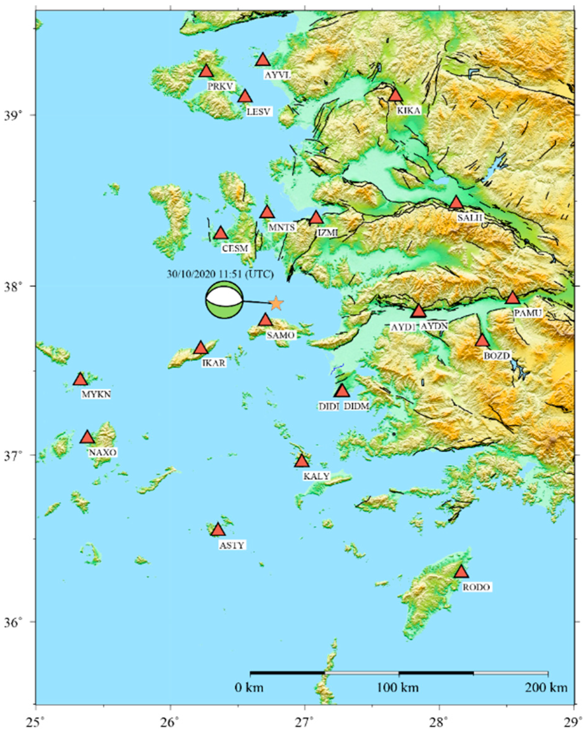
Data from 21 continuously operating GNSS stations in Turkey and Greece (Figure 1) were gathered to analyze the deformation field. Permanent stations in Turkey are from the CORS-TR network, and a local network works in the earthquake’s vicinity. In Greece, data from NOA (National Observatory of Athens) and the private company Metrica S.A. are used. The data are continuously operating GNSS data which are available 24 h a day, with 30 s intervals of gathering signals from GNSS satellites. Figure 1 illustrates the locations of the continuous stations with brown triangles. As seen in Figure 1, even though the earthquake happened in the sea, there are lots of GNSS stations that make it possible to analyze the earthquake’s characteristics because of the islands surrounding the area.
GNSS data were processed using GAMIT/GLOBK (v10.71) GNSS software [32] with the strategy of Özarpacı et al. [33]. At first, GNSS phase observations from each day were used to estimate station coordinates with loose constraints. Estimation of these coordinates involved IGS data that link regional and global networks. In the next step, loosely constrained estimates were used as quasi-observations to obtain consistent coordinates by combining IGS stations. A coordinate was determined from data collected throughout the day in 30 s intervals, and this is referred to as a daily coordinate. After estimating the daily coordinates of GNSS stations, the coseismic offsets associated with the Samos earthquake were calculated as the differences between coordinates before and after the earthquake (before 30 October and after). The standard deviations were computed using the error propagation law.
Figure 1. Map of the 2020 earthquake along with continuous GNSS stations. The yellow star indicates the epicenter of the Mw 7.0 Samos earthquake and the green beachball illustrates the point source mechanism solution of the U.S. Geological Survey (USGS). Brown triangles illustrate the GNSS stations and the thin black lines show active faults in Turkey [34].
Applsci 14 02301 g001
The Samos earthquake happened on 30 October 2020 11:51 UTC time in the Aegean Sea. Table 1 gives focal mechanism solutions from different agencies for this event.

3. Results and Discussion

Table 2 represents the 3D (XYZ) coseismic displacements of the GNSS stations along with their uncertainties. As expected, the SAMO GNSS station, located closest to the earthquake’s epicenter (as shown in Figure 1), experienced the highest displacement, and CESM, MNTS, IZMI and IKAR follow SAMO.
Stability analysis of GNSS stations was first performed by analyzing 3D Cartesian coordinates of the stations the day before and after the earthquake. In the initial iteration, with hypothesis testing, it was determined that the SAMO GNSS station was unstable. The analysis was repeated after excluding SAMO, and the CESM station was found to be unstable. By repeating the same procedure until no unstable stations remained, MNTS, IZMI and IKAR were identified to have significant displacements. Figure 2 displays the hypothesis testing process iterations, represented by various colors and corresponding geometric symbols. The text values of the stations that exceed the critical values, which provide quantitative evidence of substantial movement, indicate that those particular stations have significant displacement.
In Figure 2, all iterations are presented simultaneously. All station data used in the first iteration are indicated by red triangles. Following the first iteration, the SAMO station was removed; therefore only the first-iteration T values for that station are available with red triangles. For the second iteration, all stations are denoted by stars. In the second iteration, the ÇEŞM station was found to be unstable, exceeding the critical value, and was therefore removed. Stations exceeding the critical value were removed after the corresponding iteration until no unstable stations remained.
Applying the threshold method based on the coordinate S-transformation model confirmed the instability of the same stations for 3D cartesian coordinates. In Figure 3, red triangles represent the residuals and light blue circles represent the double value of the square root of the sum of the variances. If the residual exceeds the double value of the square root of the sum of the variances of a component of a station, this means the station is unstable. However, in the first stage, the model identified several stations and even stable ones (SAMO, CESM, MNTS, IZMI, NAXO and RODO). A single-point deformation presence on a network can contaminate not only the estimated parameters but also the residual vector; therefore, locating single-point movements can be difficult or sometimes impossible [7]. The large coseismic offset at the SAMO station made it difficult to identify the IKAR station as unstable in the first stage and to include stations with no significant displacements. By excluding the SAMO station, the model was repeated, successfully capturing the deformation at the IKAR GNSS station, while confirming the stability of the other stations (NAXO and RODO). Even though all the unstable stations were determined in the second stage, the author continued to iterate the model, extracting the unstable stations one by one, until none remained.
In Figure 3, the first iteration results are given as an example of the threshold method in the X, Y, Z components and the P point. Residuals (red triangles) larger than the T values (blue circles) define unstable points. In the first stage, it is seen that the largest residuals belong to the SAMO GNSS station with the highest red circles in multiple components.
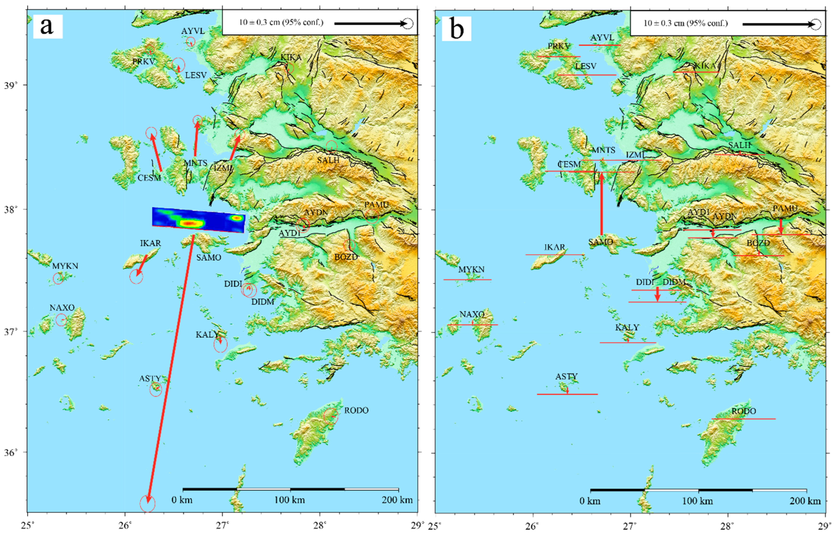
In a tectonic sense, determining earthquake characteristics and analyzing crustal deformations are more suitable with a topocentric coordinate system that is aligned with the Earth’s surface. This coordinate system allows for easy interpretation of displacement in the north, east and up directions. In Figure 4, the coseismic displacements of the Samos earthquake calculated using GNSS data are illustrated. Figure 4a,b provides visual representations of the horizontal (east and north) and vertical (up) coseismic displacements resulting from the Samos earthquake, respectively.
Figure 4a demonstrates that the horizontal coseismic displacements are dominant, although vertical offsets are required to fit a proper model [21]. The coseismic slip distribution model indicates that the slip reaches approximately 2 km from the surface and particularly in proximity to Samos Island, leading to the largest displacements observed at the SAMO continuous GNSS station. Horizontal displacements indicate (Figure 4a, Table 3) significant displacement at five stations (CESM, MNTS, IZMI, IKAR and SAMO) based on their confidence ellipses, while only SAMO has significant coseismic displacement in the up component (Figure 4b, Table 3).
S-transformation model-based hypothesis testing using north and east components identified SAMO as an unstable station in the initial iteration, followed by CESM, MNTS, IZMI and IKAR. The threshold analysis also identified the same stations as unstable. For the up component, similar results were obtained, and the two models determined only the SAMO station as unstable. Regardless of the method used, the results hold true for all dimensions and with different coordinate systems. It should be noted that these approaches do not provide displacement magnitudes, but rather determine significant displacements in GNSS stations. The S-transformation method demonstrates effectiveness in detecting unstable reference points and GNSS stations significantly affected by the earthquake, making it suitable for deformation analysis.

4. Conclusions

This study focuses on the coseismic displacements recorded at numerous stations during the Samos earthquake. According to the results, vertical offsets and horizontal displacements both contribute to the overall deformation pattern. Due to its proximity to the epicenter, the SAMO GNSS station experiences the largest displacement; however, other stations including CESM, MNTS, IZMI and IKAR also experience significant displacements.
The S-transformation model with hypothesis testing is used to evaluate station stability. Unstable stations are identified through iterations, and they are excluded from subsequent analyses until no unstable station remains. Threshold analysis is also utilized and similar results are yielded.
Additionally, the results obtained from different coordinate systems are compared and produce consistent outcomes, indicating that the results are independent from the selected coordinate system. The methods used in the study successfully identify stations significantly influenced by the earthquake, providing valuable insights for deformation analysis. Displacements obtained with geodetic methods may provide insights into the behavior of the underlying faults, the potential for seismic activities and the associated risks to nearby infrastructures. Additionally, the analysis used in this study may contribute to the development of more effective seismic hazard models and early warning systems, ultimately helping to improve resilience and preparedness in earthquake-prone regions.
It should be highlighted that stations with significant displacements can be found by the analysis, but not their magnitudes. The S-transformation method proved successful in detecting unstable reference points and stations with significant coseismic offsets, allowing for accurate evaluation of the earthquake’s effects on GNSS stations.

Funding

This research received no external funding.

Institutional Review Board Statement

Not applicable.

Informed Consent Statement

Not applicable.

Data Availability Statement

The data presented in this study are available in the article.

Acknowledgments

I would like to thank Uğur Doğan, Cüneyt Aydın and Alpay Özdemir for their help. I used GMT (Generic Mapping Tools) for the figures [35].

Conflicts of Interest

The author declares no conflicts of interest.

References

  1. Hekimoglu, S.; Erdogan, B.; Butterworth, S. Increasing the Efficacy of the Conventional Deformation Analysis Methods: Alternative Strategy. J. Surv. Eng. 2010, 136, 53–62. [Google Scholar] [CrossRef]
  2. Amiri-Simkooei, A.R.; Alaei-Tabatabaei, S.M.; Zangeneh-Nejad, F.; Voosoghi, B. Stability Analysis of Deformation-Monitoring Network Points Using Simultaneous Observation Adjustment of Two Epochs. J. Surv. Eng. 2017, 143, 04016020. [Google Scholar] [CrossRef]
  3. Aydin, C. Effects of Displaced Reference Points on Deformation Analysis. J. Surv. Eng. 2017, 143, 04017001. [Google Scholar] [CrossRef]
  4. Akpınar, B. Positioning Performance of GNSS-PPP and PPP-AR Methods for Determining the Vertical Displacements. Surv. Rev. 2021, 55, 68–74. [Google Scholar] [CrossRef]
  5. Even-Tzur, G. Extended S-Transformation as a Tool for Deformation Analysis. Surv. Rev. 2012, 44, 315–318. [Google Scholar] [CrossRef]
  6. Chen, Y.Q.; Chrzanowski, A.; Secord, J.M. A Strategy for the Analysis of the Stability of Reference Points in Deformation Surveys. CISM J. 1990, 44, 141–149. [Google Scholar] [CrossRef]
  7. Caspary, W.; Borutta, H. Robust estimation in deformation models. Surv. Rev. 1987, 29, 29–45. [Google Scholar] [CrossRef]
  8. Caspary, W. Concepts of Network and Deformation Analysis; University of New South Wales: Sydney, Australia, 2000. [Google Scholar]
  9. Wiśniewski, Z. Estimation of Parameters in a Split Functional Model of Geodetic Observations (M Split Estimation). J. Geod. 2009, 82, 105–120. [Google Scholar] [CrossRef]
  10. Wiśniewski, Z. M Split(q) Estimation: Estimation of Parameters in a Multi Split Functional Model of Geodetic Observations. J. Geod. 2010, 84, 355–372. [Google Scholar] [CrossRef]
  11. Zienkiewicz, M.H. Application of MSplit Estimation to Determine Control Points Displacements in Networks with Unstable Reference System. Surv. Rev. 2015, 47, 174–180. [Google Scholar] [CrossRef]
  12. Aydin, C. Power of Global Test in Deformation Analysis. J. Surv. Eng. 2012, 138, 51–56. [Google Scholar] [CrossRef]
  13. Jafari, M. Bayesian Approach in Stability Analysis of Monitoring Networks of Structures. Appl. Geomat. 2022, 14, 287–297. [Google Scholar] [CrossRef]
  14. Zienkiewicz, M.H. Identification of Unstable Reference Points and Estimation of Displacements Using Squared Msplit Estimation. Measurement 2022, 195, 111029. [Google Scholar] [CrossRef]
  15. Lim, M.C.; Setan, H.; Othman, R.; Chong, A.K. Deformation Detection for ISKANDARnet. Surv. Rev. 2012, 44, 198–207. [Google Scholar] [CrossRef]
  16. Guo, J.; Zhou, M.; Wang, C.; Mei, L. The Application of the Model of Coordinate S-Transformation for Stability Analysis of Datum Points in High-Precision GPS Deformation Monitoring Networks. J. Appl. Geod. 2012, 6, 143–148. [Google Scholar] [CrossRef]
  17. Even-Tzur, G. GPS Vector Configuration Design for Monitoring Deformation Networks. J. Geod. 2002, 76, 455–461. [Google Scholar] [CrossRef]
  18. Reilinger, R.E.; Ergintav, S.; Bürgmann, R.; McClusky, S.; Lenk, O.; Barka, A.; Gurkan, O.; Hearn, L.; Feigl, K.L.; Cakmak, R.; et al. Coseismic and Postseismic Fault Slip for the 17 August 1999, M = 7.5, Izmit, Turkey Earthquake. Science 2000, 289, 1519–1524. [Google Scholar] [CrossRef]
  19. Ergintav, S.; McClusky, S.; Hearn, E.; Reilinger, R.; Cakmak, R.; Herring, T.; Ozener, H.; Lenk, O.; Tari, E. Seven Years of Postseismic Deformation Following the 1999, M = 7.4 and M = 7.2, Izmit-Düzce, Turkey Earthquake Sequence. J. Geophys. Res. Solid Earth 2009, 114. [Google Scholar] [CrossRef]
  20. McClusky, S.; Balassanian, S.; Barka, A.; Demir, C.; Ergintav, S.; Georgiev, I.; Gurkan, O.; Hamburger, M.; Hurst, K.; Kahle, H.; et al. Global Positioning System Constraints on Plate Kinematics and Dynamics in the Eastern Mediterranean and Caucasus. J. Geophys. Res. 2000, 105, 5695–5719. [Google Scholar] [CrossRef]
  21. Chousianitis, K.; Konca, A.O. Rupture Process of the 2020 Mw7.0 Samos Earthquake and Its Effect on Surrounding Active Faults. Geophys. Res. Lett. 2021, 48, e2021GL094162. [Google Scholar] [CrossRef]
  22. Meng, J.; Sinoplu, O.; Zhou, Z.; Tokay, B.; Kusky, T.; Bozkurt, E.; Wang, L. Greece and Turkey Shaken by African Tectonic Retreat. Sci. Rep. 2021, 11, 6486. [Google Scholar] [CrossRef]
  23. Kiratzi, A.; Papazachos, C.; Özacar, A.; Pinar, A.; Kkallas, C.; Sopaci, E. Characteristics of the 2020 Samos Earthquake (Aegean Sea) Using Seismic Data. Bull. Earthq. Eng. 2021, 20, 7713–7735. [Google Scholar] [CrossRef]
  24. Taymaz, T.; Yolsal-Çevikbilen, S.; Irmak, T.S.; Vera, F.; Liu, C.; Eken, T.; Zhang, Z.; Erman, C.; Keleş, D. Kinematics of the 30 October 2020 Mw 7.0 Néon Karlovásion (Samos) Earthquake in the Eastern Aegean Sea: Implications on Source Characteristics and Dynamic Rupture Simulations. Tectonophysics 2022, 826, 229223. [Google Scholar] [CrossRef]
  25. Sakkas, V. Ground Deformation Modelling of the 2020 Mw6.9 Samos Earthquake (Greece) Based on InSAR and GNSS Data. Remote Sens. 2021, 13, 1665. [Google Scholar] [CrossRef]
  26. Foumelis, M.; Papazachos, C.; Papadimitriou, E.; Karakostas, V.; Ampatzidis, D.; Moschopoulos, G.; Kostoglou, A.; Ilieva, M.; Minos-Minopoulos, D.; Mouratidis, A.; et al. On Rapid Multidisciplinary Response Aspects for Samos 2020 M7.0 Earthquake. Acta Geophys. 2021, 69, 1025–1048. [Google Scholar] [CrossRef]
  27. Sboras, S.; Lazos, I.; Bitharis, S.; Pikridas, C.; Galanakis, D.; Fotiou, A.; Chatzipetros, A.; Pavlides, S. Source modelling and stress transfer scenarios of the 30 October 2020 Samos earthquake: Seismotectonic implications. Turk. J. Earth Sci. 2021, 30, 699–717. [Google Scholar] [CrossRef]
  28. Ganas, A.; Elias, P.; Briole, P.; Valkaniotis, S.; Escartin, J.; Tsironi, V.; Karasante, I.; Kosma, C. Co-Seismic and Post-Seismic Deformation, Field Observations and Fault Model of the 30 October 2020 Mw = 7.0 Samos Earthquake, Aegean Sea. Acta Geophys. 2021, 69, 999–1024. [Google Scholar] [CrossRef]
  29. Bulut, F.; Doğru, A.; Yaltirak, C.; Yalvac, S.; Elge, M. Anatomy of 30 October 2020, Samos (Sisam)-Kuşadası earthquake (MW 6.92) and its influence on Aegean earthquake hazard. Turk. J. Earth Sci. 2021, 30, 425–435. [Google Scholar] [CrossRef]
  30. Aktuğ, B.; Tiryakioğlu, İ.; Sözbilir, H.; Özener, H.; Özkaymak, Ç.; Yiğit, C.Ö.; Solak, H.İ.; Eyübagil, E.E.; Gelin, B.; Tatar, O.; et al. GPS Derived Finite Source Mechanism of the 30 October 2020 Samos Earthquake, Mw = 6.9, in the Aegean Extensional Region. Turk. J. Earth Sci. 2021, 30, 718–737. [Google Scholar] [CrossRef]
  31. Koch, K.-R. Parameter Estimation and Hypothesis Testing in Linear Models; Springer: Berlin/Heidelberg, Germany, 1999. [Google Scholar]
  32. Herring, T.A.; King, R.W.; Floyd, M.A.; McClusky, S.C. Introduction to Gamit/Globk, Release 10.7; Massachusetts Institute of Technology: Cambridge, MA, USA, 2018. [Google Scholar]
  33. Özarpacı, S.; Doğan, U.; Ergintav, S.; Çakır, Z.; Özdemir, A.; Floyd, M.; Reilinger, R. Present GPS Velocity Field along 1999 Izmit Rupture Zone: Evidence for Continuing Afterslip 20 Yr after the Earthquake. Geophys. J. Int. 2020, 224, 2016–2027. [Google Scholar] [CrossRef]
  34. Emre, Ö.; Duman, T.Y.; Özalp, S.; Elmacı, H.; Olgun, Ş.; ¸Şaroglu, F. Açıklamalı Türkiye Diri Fay Haritası. Ölçek 1:1.250.000; Maden Tetkik ve Arama Genel Müdürlüğü, Özel Yayın Serisi-30: Ankara, Turkey, 2013. [Google Scholar]
  35. Wessel, P.; Smith, W.H.F.; Scharroo, R.; Luis, J.; Wobbe, F. Generic Mapping Tools: Improved Version Released. Eos Trans. Am. Geophys. Union 2013, 94, 409–410. [Google Scholar] [CrossRef]
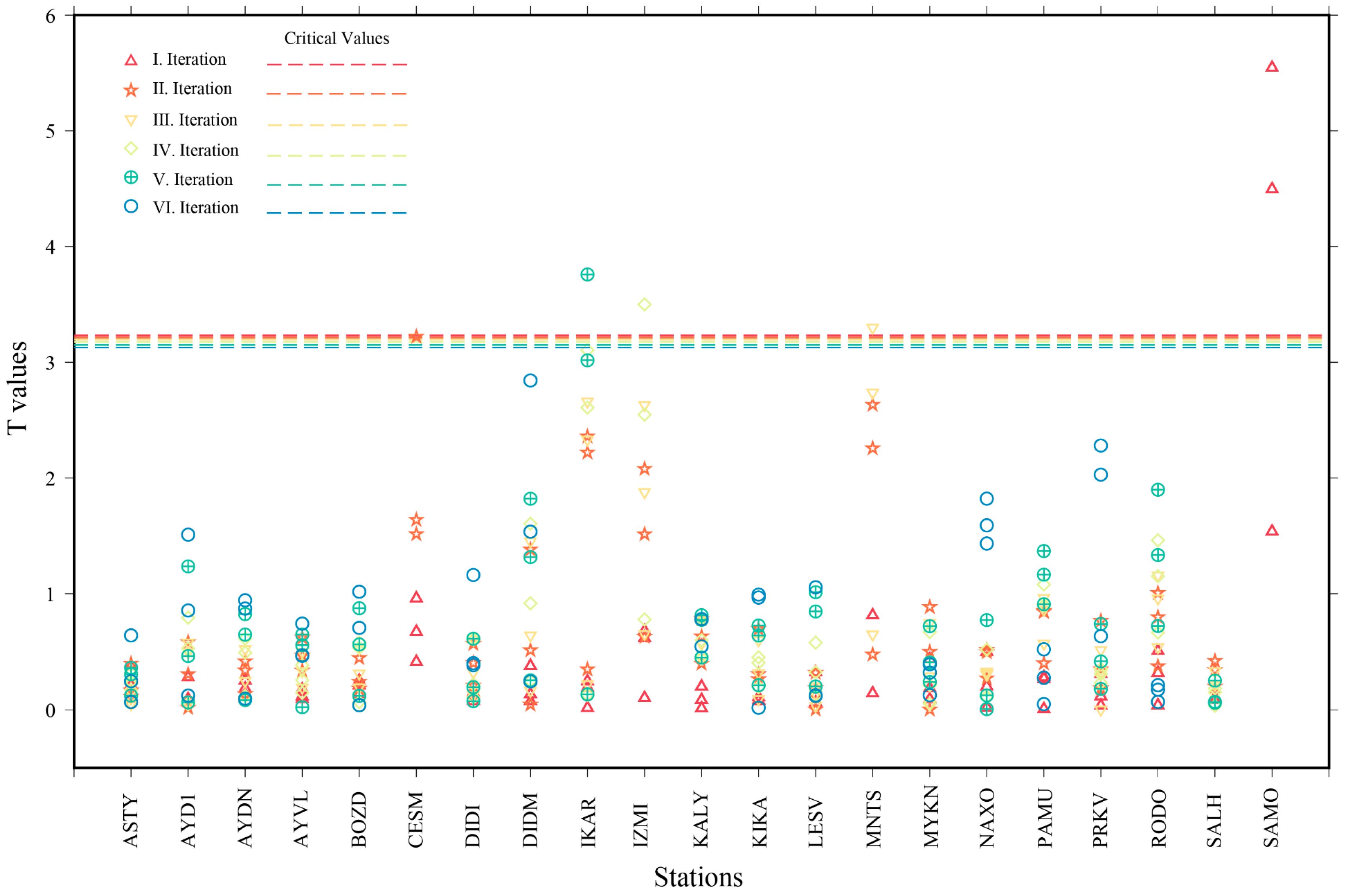
Figure 2. XYZ hypothesis testing results based on coordinate S-transformation model. Each iteration is represented by a different color and geometric symbol, while a corresponding dashed line indicates the critical values for that specific iteration.
Applsci 14 02301 g002
Figure 3. XYZ threshold method initial iteration results based on coordinate S-transformation model. Red triangles and blue circles represent the residual values and the double value of the square root of the sum of the variances, respectively.
Applsci 14 02301 g003
Figure 4. Map of GNSS coseismic displacements. Red arrows are the (a) horizontal and (b) vertical displacements with 95 percent confidence ellipses relative to Eurasia, and black lines are active faults [34]. The coseismic slip distribution model (a) is taken from Chousianitis and Konca [21].
Applsci 14 02301 g004
Table 1. Samos earthquake focal mechanism solutions [22].
Agency L o n g L a t M a g D e p t h S t r i k e D i p R a k e S t r i k e D i p R a k e
AFAD26.79437.902Mw6.917 km9543−8727046−91
USGS26.7937.918Mw7.021 km9361−9127629−88
Table 2. Coseismic XYZ displacements and st. deviations derived from GNSS measurements.
Station Name d X (mm) d Y (mm) d Z (mm) σ d X (mm) σ d Y (mm) σ d Z (mm)
ASTY−2.43−6.82−8.8413.047.099.71
AYD1−1.91−3.053.1412.237.309.65
AYDN−10.11−7.58−4.1710.376.248.25
AYVL−1.03−2.376.068.614.867.09
BOZD−7.10−6.33−0.4310.626.658.42
CESM−21.87−26.1842.3810.375.798.19
DIDI0.69−2.63−6.4010.706.258.18
DIDM−11.65−5.50−17.5612.217.089.55
IKAR23.70−4.45−22.8511.776.679.52
IZMI−24.422.0628.479.745.647.75
KALY0.410.86−12.3312.076.779.07
KIKA−2.830.034.249.365.847.88
LESV−6.94−4.536.6612.386.789.99
MNTS−31.72−11.7735.769.265.277.32
MYKN0.25−2.00−2.0710.425.357.76
NAXO−2.06−6.09−4.1411.045.748.15
PAMU−15.35−9.92−10.7211.887.599.86
PRKV−4.30−3.693.458.994.987.35
RODO1.44−6.55−0.0313.548.4610.18
SALH−6.01−3.89−0.9710.726.218.41
SAMO290.4475.35−236.9213.798.0311.05
d X , d Y and d Z are displacements in the X, Y and Z components; σ d X , σ d Y and σ d Z are standard deviation values for the displacement in the X, Y and Z components.
Table 3. Coseismic NEU displacements and st. deviations derived from GNSS measurements.
Station NameLong. E°Lat. N° d E (mm) d N (mm) σ d E (mm) σ d N (mm) d U (mm) σ d U (mm)
ASTY26.3533236.54513−5.02−4.023.373.87−9.4516.98
AYD127.8378837.84073−1.794.413.804.03−0.5316.29
AYDN27.8461437.84700−1.974.373.093.24−12.4213.95
AYVL26.6861839.31144−1.665.962.402.632.3011.63
BOZD28.3176237.67294−2.205.333.213.33−7.5814.37
CESM26.3725738.30381−13.7352.763.253.411.7714.41
DIDI27.2686637.37213−2.65−4.743.103.49−4.3614.10
DIDM27.2774037.373350.45−6.163.743.93−20.8916.15
IKAR26.2242337.62820−14.45−29.973.613.971.3216.38
IZMI27.0818238.3948112.9335.332.813.091.3813.01
KALY26.9761536.955800.58−10.343.734.51−6.8115.73
KIKA27.6722039.105991.344.882.702.890.7412.97
LESV26.5537939.10008−0.9410.393.644.02−2.1916.42
MNTS26.7174338.426583.7549.062.602.87−4.1212.33
MYKN25.3290737.44164−1.92−1.272.793.11−1.7513.41
NAXO25.3811737.09819−4.62−0.603.033.42−6.0614.15
PAMU28.5433537.92378−1.382.763.703.90−20.9616.33
PRKV26.2650039.24570−1.406.162.462.68−2.0712.11
RODO28.1616636.29260−6.451.053.954.57−1.4917.94
SALH28.1235438.48309−0.603.703.063.37−6.1914.27
SAMO26.7053337.79277−63.13−368.044.214.7686.6118.34
Long: longitude (E°); Lat: latitude (N°); d E , d N : east and north displacements; σ d E , σ d N : standard deviations for east and north displacements; d U : up displacement; σ d U : standard deviation for up displacement.
Disclaimer/Publisher’s Note: The statements, opinions and data contained in all publications are solely those of the individual author(s) and contributor(s) and not of MDPI and/or the editor(s). MDPI and/or the editor(s) disclaim responsibility for any injury to people or property resulting from any ideas, methods, instructions or products referred to in the content.