Article

DC Voltage Induces Quadratic Optical Nonlinearity in Ion-Exchanged Glasses at Room Temperature

1
Laboratory of Optics of Heterogeneous Structures and Optical Materials, Alferov University, St. Petersburg 194021, Russia
2
Institute of Machinery, Materials and Transport, Peter the Great St. Petersburg Polytechnic University, St. Petersburg 195251, Russia
*
Author to whom correspondence should be addressed.
Appl. Sci. 2024, 14(6), 2305; https://doi.org/10.3390/app14062305
Submission received: 19 February 2024 / Revised: 2 March 2024 / Accepted: 5 March 2024 / Published: 9 March 2024
(This article belongs to the Section Optics and Lasers)

Abstract

:
We demonstrate that applying DC voltage at room temperature to an ion-exchanged glass induces quadratic optical nonlinearity in a subsurface region of the glass. We associate this with the EFISH (Electric-Field-Induced Second Harmonic) effect due to the Maxwell–Wagner charge accumulation in the subsurface region of the glass, in which a conductivity gradient forms as a result of the ion exchange processing. The second harmonic (SH) signal from the soda–lime glass subjected to potassium-for-sodium ion exchange is comparable with one from the same glass after thermal poling. The signal linearly increases with the duration of the ion exchange. The lower mobility of the potassium ions results in a higher SH signal from the potassium-for-sodium exchanged glass than that from the silver-for-sodium ion-exchanged one. This phenomenon is resistant to thermal annealing: only a 500 °C anneal caused noticeable degradation of the SH signal after “charging” the specimen. The phenomenon found is of interest for characterizing graded conductivity regions and providing and controlling second-order optical nonlinearity in transparent isotropic media.

1. Introduction

By now, glassy materials have attracted a large amount of attention in different areas of applied photonics, particularly in graded-index [1,2], integrated [3,4] and nonlinear optics [5]. In many ways, this is because of the susceptibility of their properties to different kinds of modifications. For instance, thermal electric processing (or simply poling) of glasses is intensively studied because it allows for the induction of second-order optical nonlinearity (SON) in initially isotropic glasses [5], where SON is forbidden by their central symmetry. Ion exchange (IE) is another widely used technique for modifying the properties of glasses in the desired way. Enriching a subsurface region of glasses with potassium ions using IE is conventionally used to strengthen them [6,7]. Silver, potassium and thallium IEs are used to change the index of glasses for the formation of various photonic structures [4,8,9]. The injection of noble metal ions into glasses increases the luminescent properties of the rare-earth centers, if they are present in the glass [10,11]. Also, an increase in the third-order optical nonlinearity of glasses using IE was reported [12,13]. Laser irradiation or thermal treatment in a hydrogen atmosphere of glasses injected via IE with noble metal ions leads to the formation of SERS-active metal nanoparticles [14,15]. However, in terms of SON, IE glasses have been hardly mentioned.
In this paper, we study a novel phenomenon—SON obtained in IE glasses subjected to DC voltage at room temperature, the nonlinearity being comparable with that of well-known thermally poled glasses [5,16]. This phenomenon is intriguing because, first, SON being induced in glasses at room temperature has rarely been reported [17,18] (all the techniques mentioned above use thermally activated processes to form SON). Second, SON in IE glasses being controlled using DC voltage may offer new possibilities for their use in nonlinear integrated optics since the technique of waveguide formation using IE is already well established [3].
We associate the phenomenon discussed in this study with the Maxwell–Wagner effect—the accumulation of an electrical charge at interfaces of materials with different conductivities under the application of DC/AC voltage [19,20,21]. This charge forms a strong inner electric field, which, in turn, is responsible for SON—the so-called EFISH (Electric-Field-Induced Second Harmonic) effect. However, in the case of IE glass, the conductivity of the subsurface layer enriched with invasive ions differs from the interior of the glass containing only domestic ions, and instead of a sharp interface, we are dealing with a diffusion region a few microns thick. It should be noted that the SH (second harmonic) generation of laser radiation has recently been demonstrated in amorphous thin films under the influence of an electric field due to the Maxwell–Wagner charge [22]. Also, the Maxwell–Wagner effect is often taken into account in the analysis of frequency-dependent dielectric constants of materials in sandwich and composite structures [23,24,25].

2. Materials and Methods

The specimens were 1 mm thick slides of soda–lime glass, the composition of which is presented in Table 1.
The ion exchanges were carried out in a pure KNO3 melt at 365 °C or in a 95NaNO3/5AgNO3 (in wt.%) melt at 325 °C for the enrichment of the subsurface regions of the specimens with K+ or Ag+ ions, respectively. Note that, despite the glass being multicomponent, the domestic ions that preferably participate in the IE process are sodium ones, since the mobilities and diffusion coefficients of all the others are significantly lower than those of Na+ and the invasive K+/Ag+ ions from the melt [27,28,29,30], and the concentration of potassium in the used glass is low and can be neglected. We varied the duration of IE, tIE, from 15 min up to 8 h, and the specimens were fully immersed in the melt; therefore, the same IE process occurred on both sides of the glass plates.
In the charging experiments, we used an Sh0105 source (NAUEL, Schelkovo, Russia) to apply DC voltage U (we used 1300 V) to the ion-exchanged glasses using pressed stainless-steel electrodes about 1 cm2 in size. Also, we used transparent ITO electrodes, which allowed us to simultaneously measure the electric current through the specimens and the impact of the charging on their nonlinear optical properties. Note that since the experiments were carried out at room temperature, at which glass conductivity is extremely low, the electric currents were as low as fractions of nA and were measured using a picoammeter A2-4 (MNIPI, Minsk, Belarus).
To measure the signal of the second optical harmonic generated by a specimen, we used the classical Maker fringe (MF) technique [31]. A detailed description of the setup can be found elsewhere [32]. Essentially, a specimen was fixed in a rotating holder, and the second harmonic output was measured as a function of the angle of incidence of the fundamental beam of a 1.06 µm Q-switched laser generating 6 ns pulses (Litron, Rugby, UK) onto the specimen’s surface. In dynamic experiments using transparent ITO electrodes, the angle of incidence was fixed (corresponding to the maximum SH output), and the SH signal was measured as a function of time after the DC voltage was turned on and off.

3. Results and Discussion

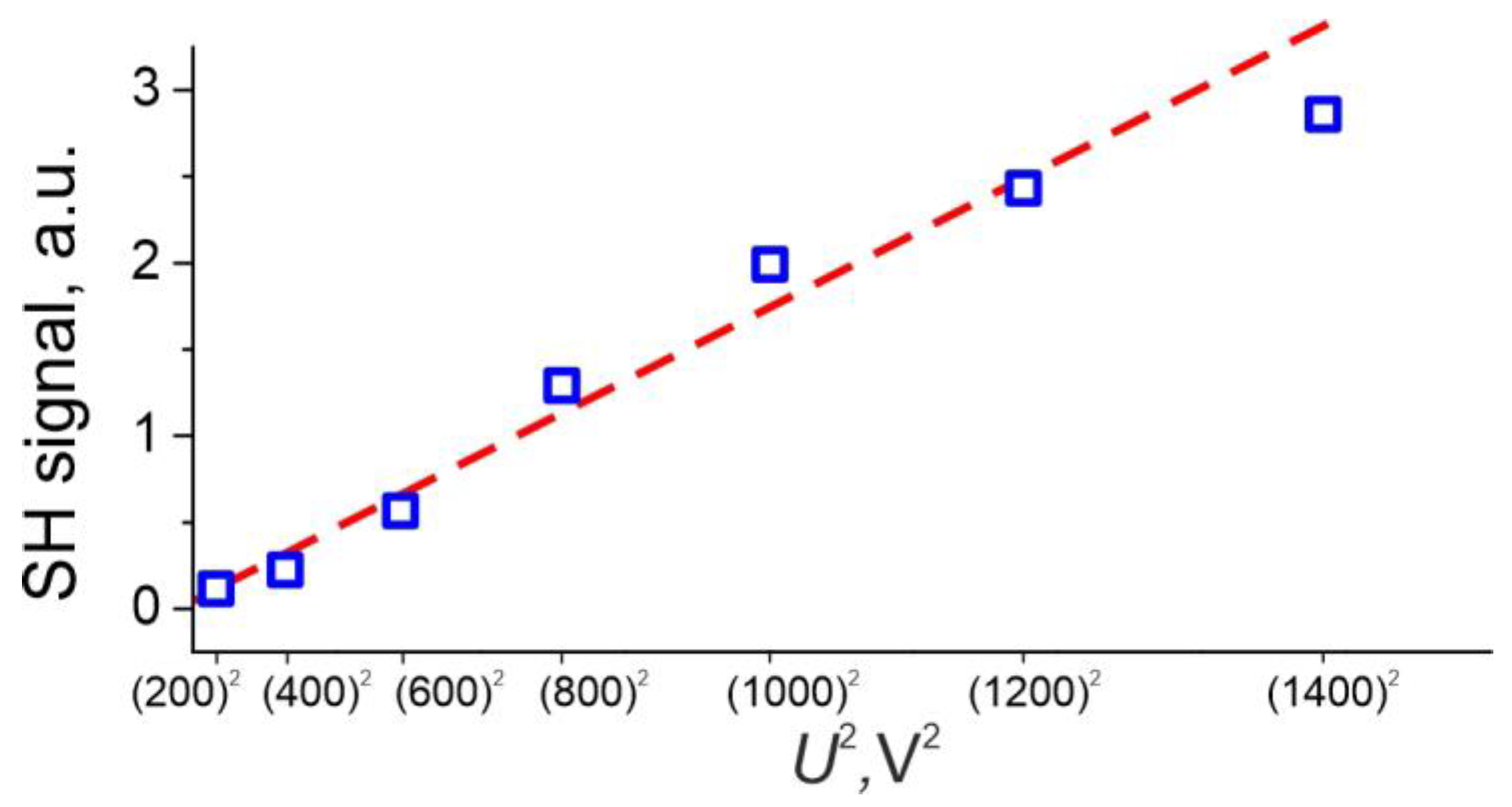
3.1. The EFISH Phenomenon in IE Glasses

In order to establish the effect of DC voltage on the second harmonic generation (SHG) capabilities of IE glasses, we measured and compared the MF of the potassium-for-sodium IE specimen before and after the application of 1300 V DC voltage for 30 min at room temperature. The dependences for the specimen exchanged for 2 h are shown in Figure 1a (dashed line, left axis—before the exposure to DC; solid line, right axis—after the exposure to DC). They are normalized to the maximal SH signal from the IE specimen before the exposure to DC voltage.
The fringes correspond to the typical interference between two SH signals generated by two opposite surfaces (or two thin subsurface nonlinear layers) of the specimen, while the bulk of the specimen is optically linear [33]. The maxima in Figure 1a correspond to the constructive interference of these signals, while the minima correspond to the destructive interference. Since the minima in Figure 1a are about zero, the magnitudes of the SH signals generated by the opposite sides of the specimen are about the same because of the equivalence of the sides, as expected.
First, we emphasize that the MFs of the virgin glass slide almost coincide with the MFs of the IE slide presented in Figure 1a (dashed blue line, left axis). Thus, we do not demonstrate the MFs of the virgin glass slide. This means that the substitution of domestic sodium ions with invasive potassium ones in the subsurface layer of the glass does not provide any noticeable change in the SON of the specimen. Therefore, the origin of the SON in both virgin and IE glasses is the same, and it is a weak natural surface nonlinearity, which all structures, including isotropic ones, possess because of the break of the central symmetry at surfaces [34]. However, the application of DC voltage produces a dramatic effect. The IE specimen exposed to 1300 V DC for 30 min demonstrates more than a 100-fold increase in the SH output (see solid red line, right axis in Figure 1a). Note that the SON gained in this case is comparable with the SON that the same glasses demonstrate after thermo-electrical poling in an open anode configuration [35]. We attribute such behavior to the EFISH effect. The electric field inducing SHG in this case originates in the Maxwell–Wagner charge formed by the current flowing through the specimen. The charge accumulates at the fuzzy interface between the regions with different conductivities, namely the subsurface region enriched in relatively slow K+ ions and the interior of the glass, where faster domestic Na+ ions dominate. Moreover, the electric potential essentially drops in the less-conductive thin subsurface K+-enriched region, forming there a high electric field responsible for the SHG. Another important difference between the observed and the classical Maxwell–Wagner (and the accompanying EFISH) effects is that the observed effect persists and slowly relaxes after the DC voltage is turned off. However, this also takes time for the charge to be accumulated (30 min in our case). This is because the dynamics of the formation and relaxation of the Maxwell–Wagner charge depends on the conductivity of materials—lower conductivity corresponds to slower charge accumulation and dissolution. In our case, the conductivity of the glass at room temperature is extremely low. Note that applying DC voltage to the virgin glass gives no optical nonlinearity [18].
Another important observation from Figure 1a is that the angular positions of the MF maxima/minima drastically changed after the IE specimen was exposed to DC voltage; i.e., the incidence angles previously corresponding to the minimum signals became corresponding to the maximum ones, and vice versa. Such changes can be caused only by the π-phase-shift of the interfacial/subsurface SH signals. This is basically a change in the sign of the SON of the interfaces/subsurface layers. We schematically demonstrate this change in Figure 1b. In the case of the virgin or uncharged IE glass, the SON is purely the surface one, and its sign is defined by the orientation of the corresponding interface. The input interface is air–glass, while the output one is glass–air. Therefore, the signs of their initial nonlinearity should be opposite (see the upper scheme in Figure 1b). On the other hand, in the case of the EFISH, the signs of the SON at the upper and lower sides of the specimen are defined by the direction of the applied electric field, which is the same for both subsurface regions (see the lower scheme in Figure 1b). Therefore, the observed change in the SON sign fits perfectly into the EFISH hypothesis.
These findings could lead to a relatively simple control of the nonlinear optical properties of K-waveguides in glass [3] using an external DC voltage. Also, this allows for the analysis of concentration and conductivity profiles, the gradient of which is responsible for the Maxwell–Wagner charge and electric field formation and, consequently, for the SHG, using high-resolution optical SH microscopy [36], rather than other, often destructive, techniques.

3.2. The EFISH vs. the IE Duration

For the SON arising under the action of an applied static electric field (the EFISH effect), one can write [5]
χ e f f ( 2 ) ~ χ ( 3 ) E D C ,
where χ ( 3 ) and χ e f f ( 2 ) are the third-order optical susceptibility and the effective (electric-field-induced) second-order optical susceptibility, respectively; EDC is the inner static electric field generated by the Maxwell–Wagner charge. Note that EDC and, consequently, χ e f f ( 2 ) generally depend on the depth coordinate (x) since the distribution of EDC is defined by the gradient distribution of slow K+ ions formed in the course of IE. We assume that the electric field is concentrated in the region thinner than the SHG coherence length, l c o h = λ 2 Δ n , where λ is the fundamental wavelength and Δn is the difference of the glass indices at the fundamental and SH wavelengths. Our estimation for the fundamental wavelength of 1064 nm is that lcoh is about 40 µm for the soda–lime glass used, which is far more than the depth of the potassium penetration in the glass under the conditions used [37]. Thus, we can consider the following relation for the intensity of the SH signal:
I 2 ω ~ χ ( 3 ) E D C ( x ) d x 2 χ ( 3 ) U K 2 ,
where UK is the voltage drop at the K+-enriched layer, which is directly proportional to the voltage applied, U, if the layer is relatively thin. UK directly depends on the resistance of this layer; therefore, UKdeff, where deff is the effective depth of the penetration of K+ ions in the glass. Since IE is a diffusive process, the effective depth is proportional to the squared root of the IE duration, d e f f t I E . In summary, the SH signal I 2 ω should linearly depend on the duration of IE, tIE:
I 2 ω ~ t I E .
We fabricated a series of specimens with the duration of IE varied from 15 min to 8 h and measured the MF of these specimens after the application of 1300 V DC voltage to them for 30 min. Note that the SON of each specimen before applying DC voltage was not different from the SON of the virgin glass slide, representing purely the surface nonlinearity. In Figure 2, we present the dependence of the maximal SH signal on the duration of IE. In Figure 2, one can observe the linear dependence (red dashed line) expected from the estimations given above. Plotted on the uniform scale, the MFs of the specimens are shown in subfigures in Figure 2.
Note that longer durations or higher temperatures of IE may result in a stronger effect as they increase the depth of the penetration of K+ ions in the glass, i.e., the thickness of the nonlinear region. However, when this depth approaches a noticeable fraction of lcoh (that is about 40 μm in the studied glass), the strengthening of the effect would slow down due to the phase-mismatching of the SHG. Thus, in our case, the limiting depth of IE is about 40 μm.
Additionally, we measured the nonlinear signal from the specimen exchanged for 2 h as a function of applied voltage. We used transparent ITO electrodes, set the angle of the fundamental light incidence corresponding to the maximal SH signal and gradually increased the applied voltage from 200 V to 1400 V with a 200 V step. We kept the specimen under each voltage for ~20 min to ensure it became fully charged and only then measured the SH signal. In Figure 3, we demonstrate the maximal SH signal as a function of the square of the applied voltage, U2. The dependence exhibits a linear trend with decent accuracy. This is in agreement with Equation (2) because UK is in a linear proportion with the voltage U applied to the specimen.

3.3. The Dynamics of the Phenomenon

Using transparent ITO electrodes, we measured the dynamics of the SON formation/degradation in the IE glass after switching the DC voltage on/off. The angle of incidence of the fundamental beam on the specimen surface was set corresponding to the maximum SH signal evaluated from the MF (see Figure 1a). Also, for these measurements, we prepared specimens with a different kind of invasive ion (Ag+). In the experiments, we used the K+ specimen exchanged for 2 h and the Ag+ specimen exchanged for 20 min. As is known [27,28,29,30], Ag+ ions are noticeably faster than K+ ions, but still slower than Na+ ions, and the choice of the durations of the IE process provides comparable penetration depths. Thus, because of the different ionic mobilities and, correspondingly, the conductivities of the IE regions, there should be a difference in the dynamics of the Maxwell–Wagner charge formation and in the EFISH in the Ag+- and K+-enriched glass slides.
In Figure 4a, we present the temporal dependences of the current flowing through the specimens while they are exposed to 1300 V DC. The dependences represent a typical charging process, like an RC circuit under DC voltage: the current decays as the charge accumulates in the specimen. The presented current decay behavior, which is of the essence, is well reproduced in our experiments, while the values of the currents fall in the range from several nA to hundreds of pA within a single temporal measurement. The current actually decays to a non-zero constant value, which corresponds to a simple Ohmic current through a specimen. Note that we normalized the dependences to fit in the [0;1] range for the sake of visual clarity. This way, we clearly see that the Ag+ specimen charges much faster than the K+ specimen: the corresponding exponential decay times are ~25 s vs. ~220 s. There are known ratios according to which the mobility of K+ ions in glass is about 80 times less than that of Na+ ions, while the mobility of Ag+ ions is about 10 times less compared to the mobility of Na+ [27,28,29,30]. Thus, the Ag+ ions should be about 8–10 times faster than the K+ ions. Note that the estimations above are valid for elevated temperatures, while the mobility values at room temperature are uncertain. Nonetheless, these estimations correlate with the difference in the characteristic times of the Maxwell–Wagner charge accumulation in the specimens.
The dynamics of the process is also evident from the SHG measurements. In Figure 4b, we present temporal dependences of the SH signal from these specimens after a 1300 V DC voltage was applied and after the DC voltage was turned off. There, we similarly observe a much faster development of the optical nonlinearity and, consequently, much faster decay of the nonlinearity in the Ag+ specimen. Also, the magnitude of the SH signal in the Ag+ specimen is about 2.5 times lower than in the K+ specimen (for the sake of visual comfort in Figure 4b, the dependence for the Ag+ specimen is 2.5 times enhanced). This also follows from the electric-field-driven nature of the nonlinearity: because Ag+ ions move faster than K+ ions, there is a smaller conductivity gradient in the Ag+ specimen, resulting in the accumulation of less Maxwell–Wagner charge and a weaker electric field.

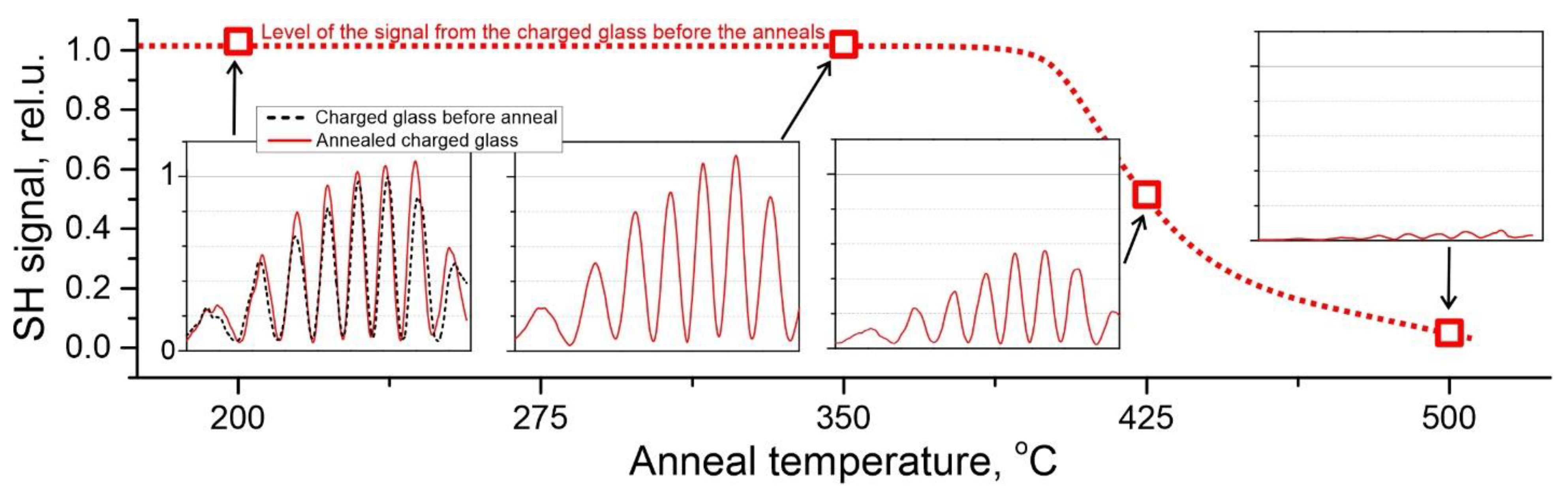
3.4. The Effect of Annealing

We investigated the thermal stability of the phenomenon under discussion. Evidently, heating a charged specimen should accelerate the decay of the induced nonlinearity. However, this does not necessarily diminish its ability to subsequently accumulate a charge. We chose the K+ specimen exchanged for 2 h and annealed it for 1 h at several temperatures lying between 200 °C and 500 °C, with the latter temperature approaching the glass transition temperature, Tg, of our glass (~560 °C). After each annealing, we subjected the specimen to DC voltage and measured its gain in optical nonlinearity. The dependence of the SH signal generated by the charged specimen on the annealing temperature is presented in Figure 5.
In Figure 5, we observe that the relatively low-temperature anneals (up to at least 350 °C) have virtually no effect on the ability of the specimen to accumulate charge and, therefore, form an inner electric field and generate the SH. This means that these temperatures are insufficient for a noticeable redistribution of the invasive K+ ions in the glass and to level the gradient of the conductivity. It is somewhat intriguing that this applies to a temperature of 350 °C, which is close to the temperature of the initial IE processing (365 °C). We speculate that this might be due to the structural changes and evolution of the glass network in the course of IE [38,39], in particular, because of the mechanical stresses caused by potassium ions, which are noticeably bigger than sodium ones. This can increase the activation energy for reverse ion shuffling. Note that since Na+ ions are much faster than K+ ions, even an inessential dilution of the K+-enriched layer with Na+ ions would noticeably level the gradient of the conductivity and significantly reduce the ability of the specimens to accumulate the Maxwell–Wagner charge. However, for the 350 °C anneal, we observe none of this: the SH signal after charging is literally the same (within several percent of the instrumental error) as it was before all the anneals (see subfigures in Figure 5). On the other hand, the 425 °C anneal resulted in a noticeable decrease in the SH signal (about 50%), indicating partial ion shuffling. The 500 °C anneal almost demolished the effect of the charging. We believe that this is due to the significantly faster diffusion of alkalis and to a stronger dilution of the potassium-enriched layer with sodium at the temperature closer to the glass Tg.
A closer look at the charging process of the specimen after the high-temperature (425 and 500 °C) anneals showed that the effect did not completely disappear after the 500 °C anneal. The fact is that the SH signal evaluated via the Maker fringes (see the rightmost subfigure in Figure 5) is understated in this case because, as we demonstrate below, the specimen is partially discharging during the measurements. In Figure 6, we present the temporal dependences of the SH signal (the fixed angle of the fundamental beam incidence corresponds to the maximum signal) from the specimens annealed at 425 °C and 500 °C after the application of a 1300 V DC voltage and after the voltage was turned off. Also, for comparison, we present there the dependence for the specimen before all the anneals (the same one that was in Figure 4).
In Figure 6, we see that the SH signal degraded noticeably (about 2-fold) for the 425 °C annealed specimen and even more (about 4-fold) for the 500 °C annealed specimen, but nonetheless not completely, whereas the MF in the rightmost subfigure in Figure 5 showed almost full degradation. Also, one can observe that the charging/discharging process became much faster after annealing at 425 °C and even more so after annealing at 500 °C (near each curve, we denoted the exponential decay time of the SH signal). This also indicates a partial leveling of the conductivity gradient after such annealing. This is the reason why the MF in the rightmost subfigure of Figure 5 (annealing at 500 °C) gave an understated value of the SH signal: the MF corresponds to the partially discharged specimen, since the duration of the measurement of the MF (a few minutes) became longer than the characteristic discharge time. Thus, the data for the SH signal obtained from the MF of this specimen (the rightmost subfigure in Figure 5) are underestimated and not sufficiently reliable for the evaluation of the ability of the specimen to accumulate the charge and generate the SH.

4. Conclusions

Thus, we have demonstrated that applying DC voltage at room temperature to ion-exchanged glass leads to the significant second optical harmonic generation of laser radiation in the subsurface region of the glass. This phenomenon arises from the break of the central symmetry of the glass by the electric field generated by the Maxwell–Wagner charge accumulated in the region with the gradient of the glass conductivity, in which ions with lower mobility are introduced. This second harmonic signal from the tested potassium ion-exchanged soda–lime glass is comparable with the signal obtained from the same kind of glass after thermal poling in an open anode configuration. The second harmonic output grows approximately linearly with the duration of the ion exchange, which correlates with the proposed simple model. The second harmonic signal obtained from the glass subjected to potassium-for-sodium ion exchange noticeably exceeds the signal from the glass subjected to silver-for-sodium ion exchange because the higher ionic mobility of silver results in a lower contrast in conductivities between the interior of the glass and the ion-exchanged region. For the same reason, the formation and relaxation times of the Maxwell–Wagner charge and the second-order optical nonlinearity induced by the electric field of this charge are longer in the case of potassium ion exchange.
The phenomenon under discussion turned out to be relatively resistant to thermal annealing. After one hour of annealing at 350 °C (the temperature approaching that of the initial IE) and below, the effect of the SON acquisition under DC voltage did not suffer the slightest recession. We associate this with changes in the glass structure induced by potassium ions that penetrated it. However, the higher-temperature anneal resulted in a noticeable degradation of the effect, although its dynamics (time for the second-order optical nonlinearity to be developed under the voltage or time of its degradation after the DC voltage was turned off) also became faster.
Finally, the Maxwell–Wagner effect, which we registered in the glass with the gradient of the charge carrier mobility provided using ion-exchange processing, can be used both to characterize graded conductivity regions and to provide and control the second-order optical nonlinearity of transparent isotropic media.

Author Contributions

Conceptualization, S.S. and A.L.; data curation, D.T.; formal analysis, S.S.; funding acquisition, A.L.; investigation, G.K.; methodology, G.K.; project administration, A.L.; supervision, D.T. and A.L.; validation, S.S. and G.K.; visualization, S.S.; writing—original draft, S.S.; writing—review and editing, D.T. and A.L. All authors have read and agreed to the published version of the manuscript.

Funding

This research was funded by the Ministry of Science and Higher Education of the Russian Federation, project number FSRM-2023-0009.

Data Availability Statement

The original contributions presented in the study are included in the article, further inquiries can be directed to the corresponding author.

Conflicts of Interest

The authors declare no conflicts of interest.

References

  1. Moore, D.T. Gradient-Index Optics: A Review. Appl. Opt. 1980, 19, 1035. [Google Scholar] [CrossRef] [PubMed]
  2. Yakhkind, A.K. Optical Graded-Index Elements Made from Glass. J. Opt. Technol. 2003, 70, 877. [Google Scholar] [CrossRef]
  3. Broquin, J.-E.; Honkanen, S. Integrated Photonics on Glass: A Review of the Ion-Exchange Technology Achievements. Appl. Sci. 2021, 11, 4472. [Google Scholar] [CrossRef]
  4. Berneschi, S.; Righini, G.C.; Pelli, S. Towards a Glass New World: The Role of Ion-Exchange in Modern Technology. Appl. Sci. 2021, 11, 4610. [Google Scholar] [CrossRef]
  5. Dussauze, M.; Cardinal, T. Nonlinear Optical Properties of Glass. In Springer Handbook of Glass; Musgraves, J.D., Hu, J., Calvez, L., Eds.; Springer Nature Switzerland: Cham, Switzerland, 2019; pp. 193–225. [Google Scholar]
  6. Gy, R. Ion Exchange for Glass Strengthening. Mater. Sci. Eng. B 2008, 149, 159–165. [Google Scholar] [CrossRef]
  7. Li, X.; Jiang, L.; Wang, Y.; Mohagheghian, I.; Dear, J.P.; Li, L.; Yan, Y. Correlation between K+-Na+ Diffusion Coefficient and Flexural Strength of Chemically Tempered Aluminosilicate Glass. J. Non-Cryst. Solids 2017, 471, 72–81. [Google Scholar] [CrossRef]
  8. Tervonen, A.; West, B.R.; Honkanen, S. Ion-Exchanged Glass Waveguide Technology: A Review. Opt. Eng. 2011, 50, 071107. [Google Scholar] [CrossRef]
  9. da Silva, B.J.P.; de Melo, R.P.; Falcão-Filho, E.L.; de Araújo, C.B. Potassium Source for Ion-Exchange Glass Waveguide Fabrication. Appl. Opt. 1997, 36, 5949. [Google Scholar] [CrossRef]
  10. Jiao, Q.; Wang, X.; Qiu, J.; Zhou, D. Effect of Silver Ions and Clusters on the Luminescence Properties of Eu-Doped Borate Glasses. Mater. Res. Bull. 2015, 72, 264–268. [Google Scholar] [CrossRef]
  11. Li, J.; Wei, R.; Liu, X.; Guo, H. Enhanced Luminescence via Energy Transfer from Ag+ to RE Ions (Dy3+, Sm3+, Tb3+) in Glasses. Opt. Express 2012, 20, 10122. [Google Scholar] [CrossRef]
  12. Karvonen, L.; Rönn, J.; Kujala, S.; Chen, Y.; Säynätjoki, A.; Tervonen, A.; Svirko, Y.; Honkanen, S. High Non-Resonant Third-Order Optical Nonlinearity of Ag–Glass Nanocomposite Fabricated by Two-Step Ion Exchange. Opt. Mater. 2013, 36, 328–332. [Google Scholar] [CrossRef]
  13. Xiang, W.; Gao, H.; Ma, L.; Ma, X.; Huang, Y.; Pei, L.; Liang, X. Valence State Control and Third-Order Nonlinear Optical Properties of Copper Embedded in Sodium Borosilicate Glass. ACS Appl. Mater. Interfaces 2015, 7, 10162–10168. [Google Scholar] [CrossRef] [PubMed]
  14. Berneschi, S.; D’Andrea, C.; Baldini, F.; Banchelli, M.; de Angelis, M.; Pelli, S.; Pini, R.; Pugliese, D.; Boetti, N.G.; Janner, D.; et al. Ion-Exchanged Glass Microrods as Hybrid SERS/Fluorescence Substrates for Molecular Beacon-Based DNA Detection. Anal. Bioanal. Chem. 2021, 413, 6171–6182. [Google Scholar] [CrossRef] [PubMed]
  15. Chen, Y.; Karvonen, L.; Säynätjoki, A.; Ye, C.; Tervonen, A.; Honkanen, S. Ag Nanoparticles Embedded in Glass by Two-Step Ion Exchange and Their SERS Application. Opt. Mater. Express 2011, 1, 164. [Google Scholar] [CrossRef]
  16. Dussauze, M.; Rodriguez, V.; Lipovskii, A.; Petrov, M.; Smith, C.; Richardson, K.; Cardinal, T.; Fargin, E.; Kamitsos, E.I. How Does Thermal Poling Affect the Structure of Soda-Lime Glass? J. Phys. Chem. C 2010, 114, 12754–12759. [Google Scholar] [CrossRef]
  17. Reshetov, I.; Scherbak, S.; Kan, G.; Kaasik, V.; Pleshakov, O.; Melehin, V.; Lipovskii, A. Controlling the Sign and Magnitude of the Nonlinear Susceptibility of Poled Glasses at Room Temperature. J. Mater. Sci. 2023, 58, 11859–11871. [Google Scholar] [CrossRef]
  18. Reshetov, I.; Scherbak, S.; Tagantsev, D.; Zhurikhina, V.; Lipovskii, A. Giant Enhancement of Optical Second Harmonic in Poled Glasses by Cold Repoling. J. Phys. Chem. Lett. 2022, 13, 5932–5937. [Google Scholar] [CrossRef]
  19. Wagner, K.W. Erklärung Der Dielektrischen Nachwirkungsvorgänge Auf Grund Maxwellscher Vorstellungen. Arch. Für Elektrotechnik 1914, 2, 371–387. [Google Scholar] [CrossRef]
  20. Iwamoto, M. Maxwell–Wagner Effect. In Encyclopedia of Nanotechnology; Springer Netherlands: Dordrecht, The Netherlands, 2015; pp. 1–13. [Google Scholar]
  21. Li, C.; Chen, G.; Qiu, X.; Lou, Q.; Gao, X. A Direct Proof for Maxwell–Wagner Effect of Heterogeneous Interface. AIP Adv. 2021, 11, 065227. [Google Scholar] [CrossRef]
  22. Karam, L.; Adamietz, F.; Michau, D.; Murugan, G.S.; Cardinal, T.; Fargin, E.; Rodriguez, V.; Richardson, K.A.; Dussauze, M. Second-Order Optical Response in Electrically Polarized Sodo-Niobate Amorphous Thin Films: Particularity of Multilayer Systems. Adv. Photonics Res. 2021, 2, 2000171. [Google Scholar] [CrossRef]
  23. Samet, M.; Kallel, A.; Serghei, A. Maxwell-Wagner-Sillars Interfacial Polarization in Dielectric Spectra of Composite Materials: Scaling Laws and Applications. J. Compos. Mater. 2022, 56, 3197–3217. [Google Scholar] [CrossRef]
  24. Vu, T.T.N.; Teyssedre, G.; Roy, S.L.; Laurent, C. Maxwell–Wagner Effect in Multi-Layered Dielectrics: Interfacial Charge Measurement and Modelling. Technologies 2017, 5, 27. [Google Scholar] [CrossRef]
  25. Liu, J.; Duan, C.G.; Mei, W.N.; Smith, R.W.; Hardy, J.R. Dielectric Properties and Maxwell-Wagner Relaxation of Compounds ACu3Ti4O12 (A=Ca, Bi 2/3,Y 2/3,La 2/3). J. Appl. Phys. 2005, 98, 093703. [Google Scholar] [CrossRef]
  26. High Quality Microscope Slides. Available online: https://www.agarscientific.com/high-quality-microscope-slides (accessed on 29 February 2024).
  27. Natrup, F.V.; Bracht, H.; Murugavel, S.; Roling, B. Cation Diffusion and Ionic Conductivity in Soda-Lime Silicate Glasses. Phys. Chem. Chem. Phys. 2005, 7, 2279–2286. [Google Scholar] [CrossRef] [PubMed]
  28. Oven, R. Analytical Model of Electric Field Assisted Ion Diffusion into Glass Containing Two Indigenous Mobile Species, with Application to Poling. J. Non-Cryst. Solids 2021, 553, 120476. [Google Scholar] [CrossRef]
  29. Doremus, R.H. Exchange and Diffusion of Ions in Glass. J. Phys. Chem. 1964, 68, 2212–2218. [Google Scholar] [CrossRef]
  30. Bos, M.; Boukamp, B.A.; Vrielink, J.A.M. Determination of Diffusion Profiles of Silver Ions in Soda-Lime–Silica Glass by X-Ray Fluorescence Spectrometry. Anal. Chim. Acta 2002, 459, 305–311. [Google Scholar] [CrossRef]
  31. Jerphagnon, J.; Kurtz, S.K. Maker Fringes: A Detailed Comparison of Theory and Experiment for Isotropic and Uniaxial Crystals. J. Appl. Phys. 1970, 41, 1667–1681. [Google Scholar] [CrossRef]
  32. Scherbak, S.A.; Reshetov, I.V.; Zhurikhina, V.V.; Lipovskii, A.A. Second Harmonic Generation By Surface of Poled Glasses: Modeling and Measurement of Maker Fringes. St. Petersbg. State Polytech. Univ. J. Phys. Math. 2021, 14, 95–113. [Google Scholar] [CrossRef]
  33. Quiquempois, Y.; Martinelli, G.; Duthérage, P.; Bernage, P.; Niay, P.; Douay, M. Localisation of the Induced Second-Order Non-Linearity within Infrasil and Suprasil Thermally Poled Glasses. Opt. Commun. 2000, 176, 479–487. [Google Scholar] [CrossRef]
  34. Rodríguez, F.J.; Wang, F.X.; Canfield, B.K.; Cattaneo, S.; Kauranen, M. Multipolar Tensor Analysis of Second-Order Nonlinear Optical Response of Surface and Bulk of Glass. Opt. Express 2007, 15, 8695. [Google Scholar] [CrossRef] [PubMed]
  35. Reshetov, I.; Kaasik, V.; Kan, G.; Shestakov, S.; Scherbak, S.; Zhurikhina, V.; Lipovskii, A. SHG in Micron-Scale Layers of Glasses: Electron Beam Irradiation vs. Thermal Poling. Photonics 2022, 9, 733. [Google Scholar] [CrossRef]
  36. An, H.; Fleming, S. Second-Order Optical Nonlinearity in Thermally Poled Borosilicate Glass. Appl. Phys. Lett. 2006, 89, 181111. [Google Scholar] [CrossRef]
  37. Bengtsson, F.; Pehlivan, I.B.; Österlund, L.; Karlsson, S. Alkali Ion Diffusion and Structure of Chemically Strengthened TiO2 Doped Soda-Lime Silicate Glass. J. Non-Cryst. Solids 2022, 586, 121564. [Google Scholar] [CrossRef]
  38. Macrelli, G.; Varshneya, A.K.; Mauro, J.C. Simulation of Glass Network Evolution during Chemical Strengthening: Resolution of the Subsurface Compression Maximum Anomaly. J. Non-Cryst. Solids 2019, 522, 119457. [Google Scholar] [CrossRef]
  39. Ingram, M.D.; Wu, M.-H.; Coats, A.; Kamitsos, E.I.; Varsamis, C.-P.E.; Garcia, N.; Sola, M. Evidence from Infrared Spectroscopy of Structural Relaxation during Field Assisted and Chemically Driven Ion Exchange in Soda-Lime-Silica Glasses. Phys. Chem. Glas. 2005, 46, 84–89. [Google Scholar]
Figure 1. (a) Maker fringes of the sodium-for-potassium IE specimen (tIE = 2 h) before (dashed blue line, left axis) and right after (solid red line, right axis) the application of 1300 V DC voltage for 30 min at room temperature; the dependences are normalized to the maximal SH signal from the IE specimen before its exposure to DC. (b) Schematic orientation of the nonlinearity in the specimen before (up) and after (down) the application of DC voltage.
Applsci 14 02305 g001
Figure 2. Maximal SH signal after the application of 1300 V DC voltage to the specimens for 30 min vs. the duration of their IE. The dependence is normalized to the signal from the 15 min specimen (the lowest one). Dashed line—guide for eyes illustrating linearity of the dependence. (ae): MF patterns (SH signal vs. fundamental light incidence angle) of the specimens for particular IE durations designated in the right upper corner of the subfigures.
Applsci 14 02305 g002
Figure 3. Maximal SH signal as a function of the square of the voltage applied to the sodium-for-potassium IE specimen (tIE = 2 h). Each measurement was taken after the specimen was kept under the corresponding voltage for 20 min. The blue boxes are the experimental data, and the red dashed line is a guide for eyes demonstrating the linearity of this dependence.
Applsci 14 02305 g003
Figure 4. Temporal dependences of (a) the currents through the K+- and Ag+-enriched IE specimens after the application of 1300 V DC voltage; (b) the SH signal from these specimens during their charging and after turning off voltage; the dependence for the Ag+ specimen is 2.5 times enhanced for visual comfort. The K+ specimen was exchanged for 2 h under 365 °C and the Ag+ specimen—for 20 min under 325 °C.
Applsci 14 02305 g004
Figure 5. Maximal SH signal from the K+ specimens exchanged for 2 h, then annealed for 1 h, and then subjected to 1300 V DC for 30 min vs. temperature of annealing. The dependence normalized to the SH signal from the charged unannealed specimen. The dotted line is a guide for eyes. Subfigures: Maker fringes (the SH signal vs. the fundamental light incident angle) of the specimens for each anneal; the curves are plotted in the uniform scale.
Applsci 14 02305 g005
Figure 6. Temporal dependences of the SH signals from the K+ specimen exchanged for 2 h and from the same specimen annealed at 425 °C and at 500 °C for 1 h when charging under 1300 V DC and after turning off voltage. The exponential decay times of the SH signal are denoted near each curve.
Applsci 14 02305 g006
Table 1. Composition (in wt.%) of soda–lime glass used in the experiments [26].
OxideSiO2Na2OCaOMgOK2OAl2O3SO3Fe2O3
Wt.%72.2014.306.404.301.201.200.300.03
Disclaimer/Publisher’s Note: The statements, opinions and data contained in all publications are solely those of the individual author(s) and contributor(s) and not of MDPI and/or the editor(s). MDPI and/or the editor(s) disclaim responsibility for any injury to people or property resulting from any ideas, methods, instructions or products referred to in the content.

