Abstract
This paper addresses the problem of describing the complex linked coupling faults of memory devices and formulating the necessary and sufficient conditions for their detection. The main contribution of the proposed approach is based on using a new formal model of such faults, the critical element of which is the introduction of roles and scenarios performed by the cells involved in the fault. Three roles are defined such that the cells of the complex linked coupling faults perform, namely, the roles of the aggressor (A), the victim (V), and both (B), performed by two cells simultaneously in relation to each other. The memory march test and applied address sequence and background determine the scenario for implementing the roles of memory faulty cells. The necessary and sufficient conditions for detecting linked coupling faults are given based on a new formal model. Formally, the undetectable linked coupling faults are defined, and the conditions for their detection are formulated using multirun memory march tests. The experimental investigation confirmed the validity of the proposed formulated statements. Based on the example of a linked coupling fault, this study demonstrates the fulfillment of the necessary and sufficient conditions for its detection using a single march test. As demonstrated in this article, employing the approach proposed by the authors, a two-pass march C test, for instance, enables the attainment of 55.42% fault coverage for linked coupling faults, inclusive of undetectable faults identified by the single-pass march test.
1. Introduction
Memory devices occupy a dominant place among the hardware components of modern computer systems. Demand for high-speed, highly integrated, low-power memory is growing unprecedentedly because cloud computing, artificial intelligence, and fifth-generation (5G) communications, among others, are positioned as the main directions of the fourth Industrial Revolution. To ensure the characteristics of modern memory of computer systems that meet the requirements of new technological advances, the necessity and importance of testing memory devices have increased sufficiently [1,2]. The main task of memory testing is to detect faulty states described by various models of their failures [3,4,5]. Among the large variety of memory faults, coupling faults, CFs, involve two memory cells, and . The types of such faults are discussed below [3,6,7,8,9].
First, in an inverse coupling fault, CFin, two cells, and , with addresses participate in the model in the fault; here, one cell influences the second and is called the aggressor (A), and the second , which is affected, is the victim (V). In this fault, a logical transition from 1 to 0 (↓) or from 0 to 1 (↑) in the aggressor leads to inverting (↕) the logical value in the victim cell , which is described by two models of inverse faults : and [3]. To represent the relation of address i of the aggressor and j of the victim, in the memory address space, the symbols ∧ and ∨ are used, which define four inverse faults = {∧, ∧, ∨, ∨}. According to the classical definitions, the symbol ∧ indicates that the address of the aggressor is less than the address of the victim . In contrast, for the symbol ∨, it is greater, . One-run march tests implement sequential access to memory cells by enumerating all addresses in an increasing or decreasing sequence. Therefore, the relation compares the values of the cells and addresses and the time of accessing them. When implementing an element of a march test with an increasing sequence of addresses (⇑) and the relation of addresses is , the address for cell is generated initially, and only after some time is the address of cell generated.
Second, in an idempotent coupling fault, CFid, during a logical transition from 1 to 0 or from 0 to 1 in the aggressor cell , a certain logical value 0 or 1 is forced to be set in the victim cell [3]. Eight faults of direct action are recognized: = {∧,0>, ∧,1>, ∨,0>, ∨,1>, ∧,0>, ∧,1>, ∨,0>, ∨,1>} [3].
Third, in a static fault, CFst, the transition of a victim cell to any state ∈ {0,1} occurs at a certain value ∈ {0,1} of the aggressor cell. Eight faults are possible: = {∧<0,0>, ∧<0,1>, ∨<0,0>, ∨<0,1>, ∧<1,0>, ∧<1,1>, ∨<1,0>, ∨<1,1>} [3].
There are single coupling faults, which can be any of the above fault models, and multiple coupling faults, consisting of a subset of single coupling faults [3]. In the set of multiple faults, unlinked multiple coupling faults are distinguished. Thus, a particular memory cell is involved in only one coupling fault included in the considered multiple faults. In general, n unlinked coupling faults involve an even number of memory cells, half of which are aggressors and half are victims. Thus, each cell of a single CF has only one role: the aggressor (A) or victim (V).
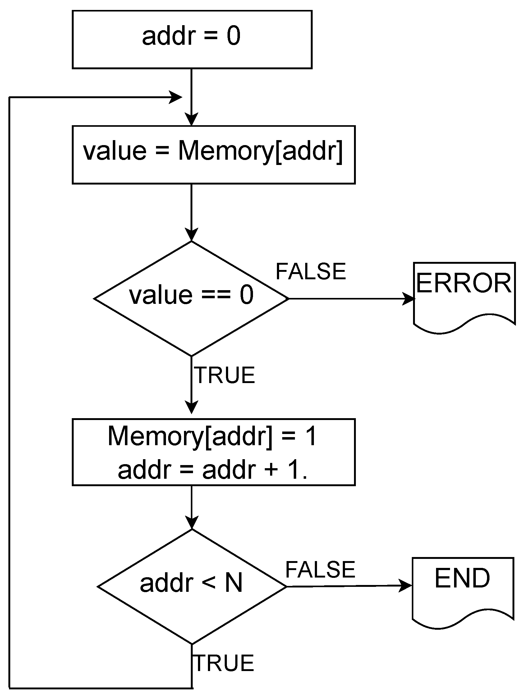
Due to the tremendous capacity of modern memory devices, tests are currently widely used. They are still being developed with a time complexity that depends linearly on the memory capacity. Such tests are called march tests [1,3,5,6,7,8,9,10] and are used for bit-oriented memory, where each cell stores one bit. A march test consists of a finite number of march elements [3]. Each march element contains a symbol that determines the order of formation of the address sequence of the cells of the memory, determining the order in which the cells are accessed. The symbol ⇑ indicates a sequential enumeration of memory addresses in increasing order ( forward), and the symbol ⇓ indicates decreasing order ( in reverse order). March elements contain a sequence of read (r) and write (w) operations, enclosed in parentheses and separated by semicolons. The transition to the next cell, according to the address sequence, is conducted only after performing all the operations with the current cell according to the march element [1,3,6,7]. For example, the simplest march element used in many tests has the form {⇑. In accordance with this element and the address sequence, 0 is read from each cell, and 1 is written. The read operation compares the read value with the expected value (0). A flowchart of this march element is presented in Figure 1.

Figure 1.
Flowchart of simple march element.
One well-known march test is the MATS+ written as:
It has three march elements ⇕, ⇑, and ⇓. Algorithm 1 presents the interpretation of this notation in pseudocode.
| Algorithm 1 MATS+ march test algorithm |
|
The detection of faults in memory, as a result of the march test, is based on receiving incorrect values read from its cells that are different from the reference ones. Thus, a faulty memory state is fixed, and a diagnostic procedure is performed if necessary [3,8,9]. Detecting single and multiple unlinked coupling faults within the march tests framework is considered solved [3]. Effective tests have proven to detect them in practice [3,6,7,11]. March tests that detect coupling faults assume a one-run memory test with a standard initial state of storage cells, usually zero, and a standard counter address sequence [3]. The problem of detecting linked coupling faults, LCFs, using one-run march tests remains practically open, requiring further research due to the variety and complexity of the manifestation mechanisms of such faults [6,7,8,9].
This article proposes a formal model of linked coupling faults, describing the roles of all cells involved in the fault and the scenario of their manifestation regarding the march test and its address sequence. The necessary and sufficient conditions for detecting such faults within the framework of one-run tests are determined, and the efficiency of their detection using multiple tests is evaluated.
In the era of rapidly advancing computing technologies and the ever-increasing importance of data integrity, our research plays an important role in ensuring the reliability of memory devices. The formal model and conditions we propose for detecting complex linked coupling faults have significant implications in various computing domains, including big data analytics, where memory errors can have cascading effects on data processing and reliability. Moreover, the ability to detect and address such faults is of paramount importance in networked systems, cloud computing infrastructure, and data storage, where data integrity and availability are critical. Our results not only contribute to the field of memory testing but also contribute to the overall robustness and reliability of computing systems.
However, these studies are limited to the detection of linked coupling memory faults. The proposed research aims to establish the necessary and sufficient conditions for detecting such faults in modern memory devices. Currently, there are no one-run march test approaches for detecting undetectable linked coupling memory faults. Most of the recent research in this area focuses on developing and enhancing march tests to detect new faults introduced by Very Deep SubMicron (VDSM) memory devices, such as , , , and . The problem of detecting linked coupling memory faults has been tackled for neighborhood pattern-sensitive faults (NPSFs). Several test algorithms have been developed to detect NPSFs, but they come with very high test complexities. As mentioned in [12], a arch test algorithm can be used for ANPSFs and PNPSFs, while it requires a march test to detect all ANPSFs, PNPSFs, and SNPSFs. Detecting very complex NPSFs is not only time-consuming but also does not guarantee the detection of undetectable faults, including CFs. The approach proposed in this paper enables the identification of previously undetectable linked coupling faults. Additionally, the proposed mathematical model for describing linked coupling memory faults may be applicable to other memory faults involving more than two cells. Nonetheless, this necessitates further rigorous and time-consuming research.
2. Linked Coupling Faults
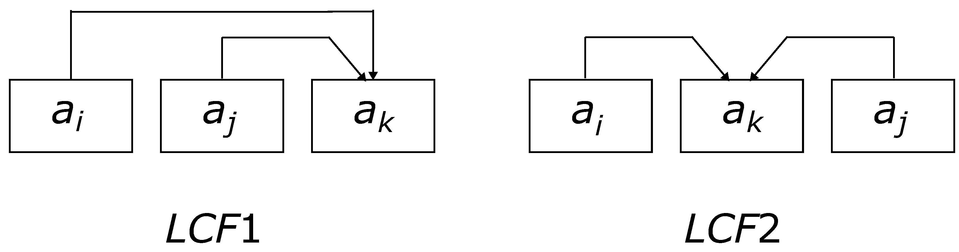
In the structure of classical models of memory faults, linked faults occupy one of the most prominent places due to the difficulty of their detection using existing march memory tests [3,6,7]. Linked faults are understood as faults of various types, including typical cells involved in several single faults. In the case of linked coupling faults consisting of n single CFs, memory cells are involved. An example of an LCF1 consisting of two single coupling faults is illustrated in Figure 2 [3]. In this figure, memory cells with addresses are presented sequentially from left to right in the time dependence of their access during the execution of the direct phase of the march test. The designations LCF1 and LCF2 refer to the same LCF where the manifestation mechanism (scenario) differs and depends on the formation time of the address of the participating cells.

Figure 2.
Linked coupling faults for .
As depicted in Figure 2, LCF1 and LCF2 involve cells and include two single CFs, each consisting of two cells. The above example of LCF1 is presented in numerous literary sources and is positioned as an example of an undetectable fault in the framework of classical march tests [3]. If we assume that the addresses of the cells , , and are formed in the sequence i, j, and k; that the cells and participate in the fault ∧; and that the cells and form a similar fault ∧, we have an undetectable fault LCF1. The fact that this fault was not detected refers to one-run march tests using an address sequence satisfying the condition of generating address i first, then j, and finally k. Then, the successive manifestation of two single faults included in the linked fault LCF1 (Figure 2) leads to a sequential double inversion of the state of the cell . Thus, the state of cell , when accessed, is always correct, and the LCF1 is undetectable. The considered example of the LCF1 linked fault is given as an argument regarding the nondetection of linked faults in general. However, in particular, the linked fault in Figure 2, consisting of two faults ∧,0> or ∧,1>, is detectable. Moreover, when using a one-run march test in which the addresses are generated in the time sequence i, then k, and finally j, the LCF1 designated as LCF2 is detectable regardless of which two CFs form LCF2.
Thus, the linked coupling fault, LCF, depends on the number, n, of single linked faults and their varieties and the number, r, of cells participating in the LCF. For the general case, the number of roles and their types, A and V, for each LCF cell is also crucial. For example, for the LCF1 where cells and play the aggressor role A, this is the only role for both cells, whereas cell has two victim roles, V. The concept of a role defines the interaction between two cells, so the cell has two roles, V, resulting from the interaction with and within the single CFs that comprise the LCF1. Abstracting from realistic and unrealistic LCFs, the sets of which are primarily determined by the design and technological features of the memory, we formulate several statements for the general case of an LCF. First, assuming that r cells participate in the LCF, we estimate the minimum, min(n), and maximum, max(n), number, n, of single coupling faults organized in the LCF. Thus, the LCF consists of single CFs, and each of the r cells is included in at least one CF. Statement 1 presents the critical factor for obtaining the boundary values of min(n) and max(n).
Statement 1.
If a is included in an LCF consisting of r cells, then the number of roles for one of the cells or forming the CF must be at least two, and the total number for both cells of the CF lies in the range from 3 to .
The validity of this statement follows from the fact that if each of the cells and forming a single CF has only one role, then this CF is not included in the LCF. Such a fault is not associated with other CFs because the cells included in this fault do not have roles that connect it with other memory cells or other CFs. Thus, the presence of at least one of the cells and of the CF of more than one role provides a connection between other single CFs, including in the LCF. Thus, the minimum number of roles for a CF in an LCF is three. The upper bound of the number of roles for the fault cells of a CF participating in the LCF (equal to ) is achieved when each of the two fault cells plays the roles of both the aggressor and victim in relation to the other cells. Two more roles are possible between the CF cells and . Then, the maximum number of roles of CF cells included in the LCF is defined as .
The minimum number (min(n)) of single CFs that form an LCF is . This result follows from Statement 1, corresponding to the minimum number of roles for each CF, two describing the CF itself, and the third defining the relationship with another CF. An example would be when, in each subsequent CF, the aggressor cell is also the victim, for which the victim cell of the current fault acts as the aggressor. Thus, min(n) = , which is also achievable for the second extreme case, where one of the rLCF cells is the aggressor for the remaining cells. We also have single CFs, where one of the cells performs more than two roles, in this case, roles. Examples of such faults LCF3 and LCF4 for are depicted in Figure 2. The maximum number (max(n)) of single CFs generating an LCF is achieved when any possible pair of cells from r cells forms two CFs, respectively, and the first cell plays the role of A, the second V, and vice versa. Thus, max. An example of an LCF consisting of the maximum number of single CFs for is presented in Figure 3 as the LCF5.
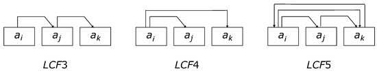
Figure 3.
Linked coupling faults for .
Thus, for an LCF consisting of r cells, the number n of single CFs forming this fault is in the following range:
The resulting limit values for the number of CFs included in the LCF correspond to similar values for the number of edges in connected labeled directed graphs consisting of r vertices. Using graph theory, the number of types of LCFs, consisting of r memory cells, can be estimated as the total number of simple labeled directed graphs with r vertices. This number grows exponentially with the number of cells r and can be used as an upper bound for the number of varieties.
The min(n) and max(n) values of the number of single CFs that form an LCF (2), including r memory cells, were obtained without considering the type of CFs, their location in the memory, and the specifics of their mutual influence on each other. Therefore, the above estimates of the number of LCF configurations only tentatively indicate numerous LCFs. We explain this by the example of the minimum number of memory cells participating in the LCF and the minimum number of single CFs describing LCFs. Considering the specific type of CF, whether it is a CFin, CFid, or CFst, and the number is 20 (see the previous section), we can conclude that two CFs involving three cells form 400 different LCFs. The estimation of 400 is given only for one of the various LCF failures that can occur in the case of specific physical memory cells, considering their relative position. As indicated in the above example of the number of LCFs involving only three cells, the number of such faults is exceptionally high. Even in this case (a small number of cells participating in the LCF), the number of LCFs and their diversity do not allow for analyzing each of these faults for detection or nondetection, which was possible for single CFs [3].
3. Necessary and Sufficient Conditions for LCF Detection
The problem of detecting single and multiple CFs has long been the primary stimulus for developing new march tests [3]. The widely known March C and March C- tests, developed to detect all kinds of single CFid faults, are very effective in detecting faulty memory states and their low time complexity [3,7]. Within the framework of one-run march tests, the March M test was developed, in which the conditions for detecting coupling faults were implemented for the first time, including double coupling faults of various configurations [13]. More efficient tests were proposed by ascertaining the presence of undetectable LCFs using one-run march tests, such as the March LR and March LA [13,14]. These tests provided conditions for detecting realistic LCFs within the considered models of linked faults and determining the technological and design features of the memory under testing [13,14]. Various modifications of the March LR and March LA tests are effectively used to detect dynamic unlinked faults [15], test dynamic memory (DRAM) [16], and implement memory built-in self-tests (BISTs) [17,18]. Specific march tests, such as March SS, March BLC-Opt, March SR, March MSS, and March m-MSS, are applied to cover bit-line coupling faults [19,20,21] and their diagnoses by applying March Cd [22].
The required sets of march elements and their sequence in the testing were determined as conditions for detecting various types of LCFs, ensuring the detection of all faults of the considered type [3]. For example, the condition for detecting all single CFids and all linked double LCFids is the presence in the test of the following marching elements ⇑; ⇑; ⇓; ⇓. In turn, the conditions for the presence of the necessary march elements in the test were formulated based on the conditions for activating a particular fault and the conditions for its detection. Similar conditions apply to the memory cells directly involved in the fault and describe the sequence of actions necessary to detect the fault. For the simplest CF of the form ∧,0>, where cell is the aggressor (↑) and cell is the victim (0), the following conditions must be fulfilled sequentially. First, the initial setting of both cells to the initial state is necessary: cell to State 0 and cell to State 1. Then, the fault activation condition is executed to perform a 0 to 1 state change in cell . Finally, the condition for detecting the fault results from reading the content (0) of cell and comparing it with the reference (previously set in cell ) value equal to 1.
To obtain and formulate the conditions for detecting complex, numerous, and diverse configurations of linked coupling faults LCF( including r cells with an ordered relation of addresses , we introduce their formal description. The basis of such a description is the role of each cell of the considered LCFs concerning all other cells included in the fault description. Similarly, as in the simplest case of a CF, two cells, and , where , can influence each other. One can be a victim (V) and the other an aggressor (A). In the examples of fault models LCF1, LCF2, LCF3, LCF4, and LCF5, the roles of each cell are indicated by links and arrows. For the general case, within the framework of linked faults that combine two single CFs that include the same two cells, and , we introduce the third role (both, B) of cell , which means two roles, A and V, for cell . Accordingly, cell in relation to also has two roles, V and A, denoted by the same symbol B. The absence of a connection (roles) between cells and is denoted by the symbol (-). Thus, in the description of the LCF, all participating cells and all their respective roles are presented.
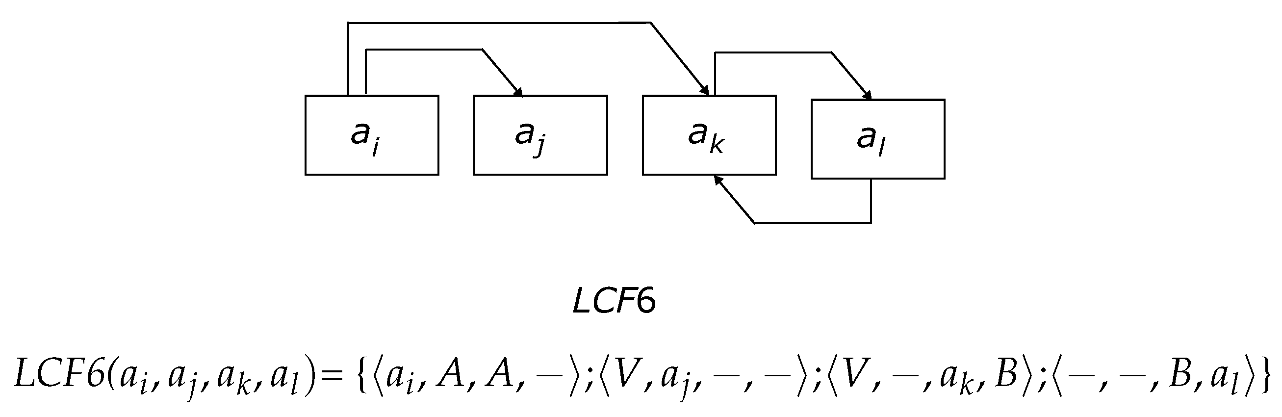
In the formal description of LCF(, the information is sequentially presented in the form of a set of symbols (−, A, V, and B) for all cells . When describing cells, their sequence is also preserved (i.e., the first position of all the descriptions contains information about cell , then , and so on). This sequence is determined by the cell access time, corresponding to the sequence of their addresses for single march tests. As an example, we consider LCF6 presented in graphical form and the form of a new formal model (Figure 4).
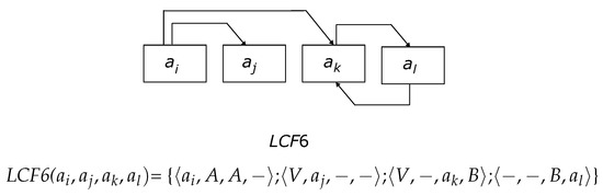
Figure 4.
Linked coupling fault LCF6 with description.
In the above example, LCF6 cells and , included in this fault, form two simple CFs and act in relation to each other in both roles, indicated by the symbol B in the description of LCF6 (Figure 4). As explained, B indicates that the cell has two roles, and which one it performs is determined by the scenario, set by the sequence of accessing the cells within the framework of the march test. Depending on the direct ⇑ addressing, when the addresses are related as follows , or are reversed ⇓, when , the LCF6 description is presented as follows:
As noted, the ordered ratio of cell addresses involved in the LCF failure corresponds to the time sequence of access to them within the framework of one-run march tests with a fixed address sequence. The relation of the values of the physical cell addresses in the LCF and the relation of the access times to these cells can be different. An example of such a situation is the failure presented in Figure 2. Physically, this is the same fault. However, its manifestation depends on the address sequence, which is displayed in the description of this fault for two cases of address sequences:
Similarly, any of the possible LCFs are described. Examples of such descriptions for the previously given LCFs are provided below:
The main advantage of the formal model for describing the configurations of linked faults is its compact notation containing complete information about all single CFs that form the LCF. For example, from the description of LCF1, it follows that this linked fault is formed from two single CFs: = , and = , .
The ordered access to the cells of the fault LCF(, when implementing the march test element, is determined by the time sequence of generating their addresses . This sequence is a crucial element of the formal description of the LCF, which, for example, can be observed from the descriptions (4) of the LCF in Figure 2. Indeed, for the sequence of addresses , and k, we have the LCF1 description of the fault, and for and j, another description is used: LCF2 (4). The position of a particular cell (e.g., cell in its description) and the description itself in the formal LCF model correspond to the temporal order of accessing this cell when implementing the march test element. For example, in the formal model LCF1 = {;;}, the description of cell is in the third position because the test generates the address k after forming addresses i and j. In the description of of cell , its designation is also given in the third position.
Thus, the basis of the new formal LCF model is the three roles that the cells of the linked coupling fault perform, aggressor (A), victim (V), and both (B), performed by two cells simultaneously in relation to each other. In reality, the proposed model describes the scenario for implementing the roles of memory fault cells, determined by the march test and the address sequence in this test to access the cells. For tests with a maximum fault coverage CF, the scenario is specified only by the address sequence, displayed in the formal LCF model, as demonstrated in the examples of LCF1 and LCF2.
For each cell , the LCFs distinguish between the left and right in the description. Moreover, those fault cells activated before activating the current cell are on the left side and are on the right side after activation. Activation refers to accessing a memory cell under the march element of the test and performing the corresponding write and read operations. The formal LCF model allows us to formulate the conditions for detecting such faults using one-run march tests.
Statement 2.
The necessary and sufficient conditions for detecting a linked coupling fault LCF( are listed below.
- 1.
- The application of a march test with an arbitrary address sequence, which detects all kinds of single coupling faults.
- 2.
- The presence in the formal model LCF( of a fault that corresponds to the address sequence of the applied test, at least one cell , , where only one role V is present in the right, or on the left side of the description, or in both parts.
As demonstrated, an arbitrary fault LCF( is a composition of single CFs, where the entire set is detected by march tests, for example, the March LA and March LR [13,14]. All possible single CFs are guaranteed to be detected by the indicated tests only if they are not included in the LCF fault. When single CFs are included in the LCF, these tests detect them either by the wrong state of the aggressor cell or are guaranteed to provide a condition for their activation by changing the state of the victim cell and detecting the wrong state. When the aggressor cell cannot fulfill the activation condition, the presence of a faulty memory state (an LCF) is detected by the wrong state of this cell because tests that detect single CFs provide the conditions for activating all such faults by setting the required initial state of the aggressor cell or performing a transition in it (see CFin, CFid, and CFst) [3]. Thus, all CF aggressor cells included in the LCF are either the cause of their detection, becoming victims within other CFs, or exercise their influence on the victim cells.
In most cases, these tests detect changes in the victim cells relative to the original reference values [3], which follows from the properties of tests that detect the complete set of single coupling faults [3]. The exception is cases of masking that occur when several aggressors influence one cell of the victim. For example, one aggressor changes the reference value of the victim to the opposite, and the second aggressor returns the original value of the victim cell. An example of masking is illustrated in Figure 2 and is described by the formal model LCF1 (4). As observed in this case, cell has two victim roles (4), and both are on the same (right) side in the description. When the victim cell has only one victim role (i.e., only one aggressor) before accessing this cell, masking is impossible. If the cell has two victim roles simultaneously, but in both parts of the formal description, the cell content is only read after a single change in its state due to the manifestation of a CF. Accordingly, an LCF is detected. A similar case is illustrated by an example of an LCF2 with the formal description of two roles of the victim LCF3 of cell . However, in this case, one role, V, is on the right, and the second, V, is on the left in the formal description.
The masking mechanism is very diverse and is typical for memory devices. However, within the framework, this article considers the case of a memory LCF and the possible masking of the CFs included in them [23].
The guaranteed detection of any fault in the mutual influence of the CF, regardless of whether it is included in the linked fault of the LCF, is provided by analyzing the state of the victim cell by reading its state after realizing the influence of only one aggressor on it (see Statement 2). An example of the implementation of such a scenario is described by the formal model LCF3, where the state of the victim cell () is analyzed after only the aggressor cell has been influenced. The presence of at least one cell , of the formal model LCF( in the description, where there is only one victim role (on the right or left or both simultaneously), ensures the detection of LCF(, which is a necessary and sufficient condition for LCF detection using a test covering single CFs.
As demonstrated, the cell role B in the LCF consists of two roles, each realized in one of the two phases of the test, direct or reverse, which is equivalent to having one role of the victim on the right or left side of the LCF description. The presence of two roles (V and B) on the right or left of the description of at least one cell in the LCF also guarantees the detection of this fault because, in one of the phases of the test, the role of B is equivalent to the role of A. Accordingly, this case is reduced to the case of the presence of one role of the victim. Thus, in the formal model LCF(, corresponding to the scenario of the address sequence of the test, a necessary and sufficient condition for detecting this fault is at least one cell that has only one of the roles of the victim V or B, or both simultaneously on the right or left.
Returning to the fault in Figure 2 for a sequence of addresses , and k of a test that detects single communication faults and its description {;;}, this fault was not detected because the conditions of Statement 2 were not met. Using other address sequences (other scenarios) can ensure its detection, as demonstrated by various descriptions of this fault, depending on the time sequence of access to the cells in this fault:
In two (LCF() and LCF()) of the six cases in (5), the conditions of Statement 2 are satisfied, providing the necessary and sufficient conditions for their detection.
4. Multirun March Tests for LCF Detection
Multi-cell faults such as pattern-sensitive faults (PSFs) or linked coupling faults (LCFs) are triggered when specific bit patterns occur in the cells affected by these faults or when a certain value change occurs in one of the cells. Due to the limitations of march tests, a single run of such a test can only generate a limited number of patterns in the selected memory cells. Increasing the number of generated patterns in memory cells cannot be achieved by simply increasing the test’s complexity. One effective solution for achieving high fault coverage for multi-cell faults, as demonstrated in [24,25,26,27,28,29,30], is multirun testing. This testing concept involves executing the same test procedure multiple times, each time with different initial conditions (different initial memory backgrounds and/or address sequences). Executing the same march test under varying initial conditions generates different bit patterns in memory cells, thereby enabling the detection of a wider range of potential multi-cell faults, including various types of linked coupling faults.
The low coverage of LCFs by classic one-run march tests is explained by the sequential procedure for accessing memory cells and the unchanged test implementation scenario [23]. Analyzing the example of six formal descriptions (5) of the LCF1 in Figure 2 reveals that only two of the six scenarios guarantee the detection of this fault. Accordingly, the fault can be detected only by changing the scenarios and repeatedly applying the test. In this case, the scenario is the address sequence of the march test that detects the entire set of single coupling faults. Multiple (multirun) memory testing was considered within the exhaustive, pseudo-exhaustive, and transparent memory testing frameworks [3,23]. In all cases, it was necessary to repeat the march test for various scenarios determined by the degrees of freedom inherent in march tests [20]. March memory tests detect complex faults by applying them repeatedly for various address sequences or initial memory cell states [31]. An essential result of multirun memory testing is detecting all possible faulty states. However, achieving coverage may require a sufficient number (multiplicity) of test applications.
For the variable address sequence that defines the scenario for LCF(, a time sequence always exists for accessing cells , satisfying the conditions of Statement 2. An example is LCF1 (5), where two of the six sequences of cell addresses , and are detectable for this fault. In the general case, for any faulty memory state, a set of address sequences exists for which this memory state is detected by a single test. Accordingly, in a random address sequence selection procedure, the ratio p, representing the number of address sequences for which a fault is detectable, to the total number of sequences, expressed as a percentage, determines the fault coverage, , when detecting this fault using a one-run memory test with randomly selected address sequences. The value of can be understood as the probability of fault detection, while the probability of this fault remaining undetectable is . For an f-run memory test with a random address sequence selection procedure, the probability of this fault being undetectable is and the detection probability is estimated as . Assuming that a single application of the march test allows for detecting the LCF failure with , its f-time use with arbitrary (random) address sequences allows for reaching the value determined as follows (6) [23]:
As f increases, the value of the fault coverage tends to 100%. For the LCF1 failure, considering (5), 33.33%.
5. Experimental Investigations
The first experiment was provided according to the following conditions:
- Memory size: 1024 one-bit cells;
- LCF1 consisting of two single CFins: = and = in cells , and with addresses ;
- Address sequence: random;
- Number of one-run march test executions for the average value of calculation: 100,000.
The results for the one-run memory testing in Table 1 satisfy the theoretical estimation (6) for march tests. The results in Table 1 originate from computer simulations conducted using custom tools developed by the authors. These simulations involved generating LCF1s in random memory cells and then executing the relevant test to detect the faults. For each test, 100,000 simulations were conducted, and the result of the test was recorded each time. Finally, the average fault coverage () was calculated based on these simulations. The number of simulations was limited to 100,000 because it was observed that further increasing the number of simulations did not significantly affect the obtained average result.

Table 1.
Fault coverage of LCF1 for one-run march tests.
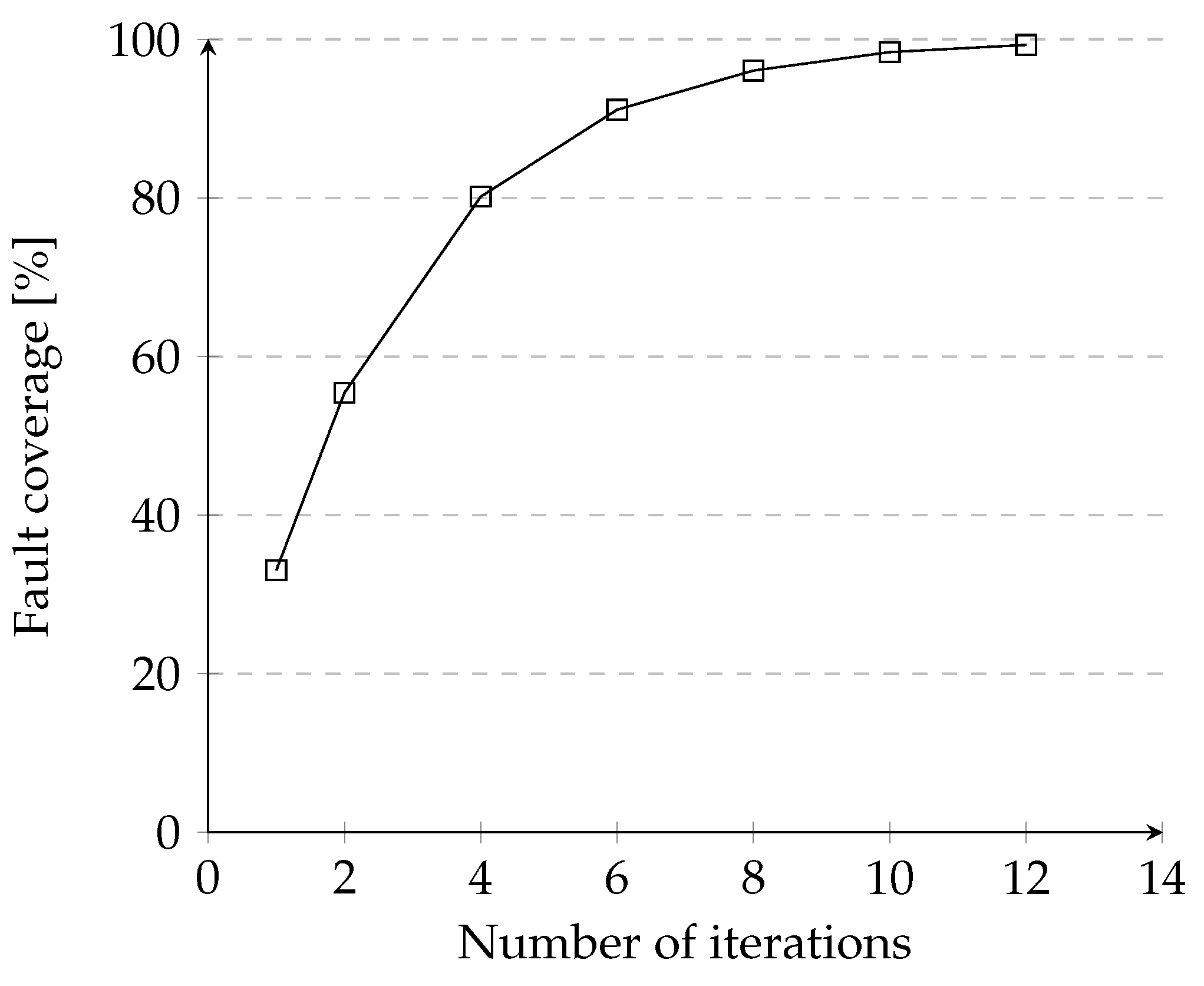
The next experiment confirms the validity of the relation (6) for multirun memory testing by applying the March C- test. The results of this experiment for the same LCF1 are provided in Figure 5. The results demonstrate the high efficiency of detecting LCF1s using multirun memory tests.
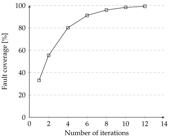
Figure 5.
Fault coverage of LCF1 for multirun March C- test (address sequences: random, and background: zeros).
The efficiency of multirun memory testing for detecting linked coupling faults was validated for various LCF and memory tests. The experiment conditions are similar to the previous ones, except for the LCF fault configurations. The critical element of the multirun testing for this experiment is a random address sequence applied at each test iteration.
It should be noted that the proposed approach is applicable for detecting previously undetectable memory linked coupling faults using march tests. March tests exhibit computational complexity that linearly depends on the memory size N in bits. The approach shares comparable computational complexity with classical march tests and also linearly depends on the memory size. For instance, the March LR test has a complexity of 22N, but it does not enable the detection of undetectable linked coupling faults. Conversely, based on the proposed approach, the MATS+ application (5N), in a multirun scenario (four runs), facilitates the detection of 89.57% of the undetectable linked coupling faults (see Table 2). The complexity of this procedure is estimated as 4 × 5N = 20N.
Table 2.
Fault coverage of the LCF for the multirun MATS+ test (address sequences: random, and background: zeros).
Table 2 and Table 3 list the high efficiency of detecting complex faults with multirun tests. With an increase in the number of iterations, the test efficiency levels off. As listed in Table 2 and Table 3, after four iterations, test MATS+ has the same effectiveness as the more complex test March C- designed as a CF detection test.
Table 3.
Fault coverage of the LCF for the multirun March C- test (address sequences: random, and background: zeros).
A similar dependence is also observed for the case of multirun tests based on a variable initial memory state (random backgrounds) of the tested memory. The same faults were analyzed as in the previous experiment, and the March C- and simplest one-phase tests {⇑ were used. The results for both cases are presented in Table 4 and Table 5.
Table 4.
Fault coverage of the LCF for the multirun March C- test (address sequences: counting sequences, and background: random).
Table 5.
Fault coverage of the LCF for the multirun {⇑ test (address sequences: counting sequences, and background: random).
6. Conclusions
A formal mathematical model is proposed to describe linked coupling faults, based on the behavior of cells involved in the fault. The cell behavior scenario is determined by the address sequence of a one-run march test. The necessary and sufficient conditions for detecting linked coupling faults are provided. Theoretically and experimentally, undetectable LCFs are effectively detected by multirun tests using random address sequences and variable initial memory states. The experiments demonstrate the high efficiency of detecting LCF1s using multirun memory tests. For instance, an eight-run test with a random background technique achieves 100% coverage of LCF1s, even for simple tests, like the “one march element” ( {⇑). The proposed mathematical model for linked coupling faults appears promising for their identification and diagnostic localization. It is crucial in further research to utilize the mathematical model proposed by the authors to describe other complex memory faults, including other types of undetectable faults, especially neighborhood pattern-sensitive faults (NPSFs). This approach, according to the authors, will enable the formulation of necessary and sufficient conditions for detecting other types of complex memory faults.
Author Contributions
Conceptualization, V.N.Y.; Methodology, V.N.Y.; Validation, V.N.Y. and I.M.; Formal analysis, V.N.Y. and I.M.; Investigation, V.N.Y. and I.M.; Writing—review & editing, V.N.Y. and I.M. All authors have read and agreed to the published version of the manuscript.
Funding
This paper was supported by grant WZ/WI-IIT/3/2023 from the Faculty of Computer Science at Bialystok University of Technology, Ministry of Science and Higer Education, Poland.
Institutional Review Board Statement
Not applicable.
Informed Consent Statement
Not applicable.
Data Availability Statement
The original contributions presented in the study are included in the article, further inquiries can be directed to the corresponding authors.
Conflicts of Interest
The authors declare no conflicts of interest.
References
- Lee, K.; Kim, J.; Baeg, S. Fault Coverage Re-Evaluation of Memory Test Algorithms With Physical Memory Characteristics. IEEE Access 2021, 9, 124632–124639. [Google Scholar] [CrossRef]
- Wojciechowski, A.A.; Marcinek, K.; Pleskacz, W.A. Configurable MBIST Processor for Embedded Memories Testing. In Proceedings of the 2019 MIXDES—26th International Conference “Mixed Design of Integrated Circuits and Systems”, Rzeszow, Poland, 27–29 June 2019; pp. 341–344. [Google Scholar] [CrossRef]
- Goor, A.J.v.d. Testing Semiconductor Memories: Theory and Practice; John Wiley & Sons: Chichester, UK, 1991. [Google Scholar]
- Hamdioui, S.; Gaydadjiev, G.; Van de Goor, A.J. The state-of-art and future trends in testing embedded memories. In Proceedings of the Records of the 2004 International Workshop on Memory Technology, Design and Testing, San Jose, CA, USA, 10 August 2004; IEEE: Piscataway, NJ, USA, 2004; pp. 54–59. [Google Scholar] [CrossRef]
- Koshy, T.; Arun, C.S. Diagnostic data detection of faults in RAM using different march algorithms with BIST scheme. In Proceedings of the 2016 International Conference on Emerging Technological Trends (ICETT), Kollam, India, 21–22 October 2016; pp. 1–6. [Google Scholar] [CrossRef]
- Caşcaval, P.; Bennett, S. Efficient march test for 3-coupling faults in random access memories. Microprocess. Microsyst. 2001, 24, 501–509. [Google Scholar] [CrossRef]
- Caşcaval, P.; Caşcaval, D. March test algorithm for unlinked static reduced three-cell coupling faults in random-access memories. Microelectron. J. 2019, 93, 104619. [Google Scholar] [CrossRef]
- Nor, A.; Zakaria, N.; Wan Hasan, W.; Abdul Halin, I.; Sidek, R.; Wen, X. Fault Detection with Optimum March Test Algorithm. In Proceedings of the 3rd International Conference on Intelligent Systems Modelling and Simulation, ISMS 2012, Kota Kinabalu, Malaysia, 8–10 February 2012; Volume 47. [Google Scholar] [CrossRef]
- Cockburn, B.F. Deterministic Tests for Detecting Single V–Coupling Faults In RAMs. J. Electron. Test. 1994, 5, 91–113. [Google Scholar] [CrossRef]
- Harutyunyan, G.; Shoukourian, S.; Vardanian, V.; Zorian, Y. A New Method for March Test Algorithm Generation and Its Application for Fault Detection in RAMs. IEEE Trans. Comput.-Aided Des. Integr. Circuits Syst. 2012, 31, 941–949. [Google Scholar] [CrossRef]
- Jidin, A.Z.; Hussin, R.; Mispan, M.S.; Fook, L.W. Novel March Test Algorithm Optimization Strategy for Improving Unlinked Faults Detection. In Proceedings of the 2021 IEEE Asia Pacific Conference on Circuit and Systems (APCCAS), Penang, Malaysia, 22–26 November 2021; pp. 117–120. [Google Scholar] [CrossRef]
- Jidin, A.Z.; Hussin, R.; Fook, L.W.; Mispan, M.S. A review paper on memory fault models and test algorithms. Bull. Electr. Eng. Inform. 2021, 10, 3083–3093. [Google Scholar] [CrossRef]
- van de Goor, A.; Gaydadjiev, G.; Mikitjuk, V.; Yarmolik, V. March LR: A test for realistic linked faults. In Proceedings of the 14th VLSI Test Symposium, Princeton, NJ, USA, 28 April–1 May 1996; pp. 272–280. [Google Scholar] [CrossRef]
- van de Goor, A.; Gaydadjiev, G.; Yarmolik, V.; Mikitjuk, V. March LA: A test for linked memory faults. In Proceedings of the European Design and Test Conference. ED and TC 97, Paris, France, 17–20 March 1997; p. 627. [Google Scholar] [CrossRef]
- Ying, L.W.; Hussin, R.; Ahmad, N.; Fook, L.W.; Jidin, A.Z. Modified March MSS for Unlinked Dynamic Faults Detection. In Proceedings of the 2022 IEEE 20th Student Conference on Research and Development (SCOReD), Bangi, Malaysia, 8–9 November 2022; pp. 68–72. [Google Scholar] [CrossRef]
- Chou, C.W.; Chen, Y.X.; Li, J.F. Testing Inter-Word Coupling Faults of Wide I/O DRAMs. In Proceedings of the 2015 IEEE 24th Asian Test Symposium (ATS), Mumbai, India, 22–25 November 2015; pp. 67–72. [Google Scholar] [CrossRef]
- Manasa, R.; Verma, R.; Koppad, D. Implementation of BIST Technology using March-LR Algorithm. In Proceedings of the 2019 4th International Conference on Recent Trends on Electronics, Information, Communication Technology (RTEICT), Bangalore, India, 17–18 May 2019; pp. 1208–1212. [Google Scholar] [CrossRef]
- Jidin, A.Z.; Hussin, R.; Mispan, M.S.; Lee, W.F.; Zakaria, N.A. Implementation of minimized March SR algorithm in a memory BIST controller. J. Eng. Technol. (JET) 2023, 13, 67–80. [Google Scholar]
- Irobi, S.; Al-Ars, Z.; Hamdioui, S. Detecting memory faults in the presence of bit line coupling in SRAM devices. In Proceedings of the 2010 IEEE International Test Conference, Austin, TX, USA, 2–4 November 2010; pp. 1–10. [Google Scholar] [CrossRef]
- Zordan, L.B.; Bosio, A.; Dilillo, L.; Girard, P.; Pravossoudovitch, S.; Virazel, A.; Badereddine, N. Optimized march test flow for detecting memory faults in SRAM devices under bit line coupling. In Proceedings of the 14th IEEE International Symposium on Design and Diagnostics of Electronic Circuits and Systems, Cottbus, Germany, 13–15 April 2011; pp. 353–358. [Google Scholar] [CrossRef]
- Azevedo, J.; Virazel, A.; Bosio, A.; Dilillo, L.; Girard, P.; Todri, A.; Prenat, G.; Alvarez-Herault, J.; Mackay, K. Coupling-based resistive-open defects in TAS-MRAM architectures. In Proceedings of the 2012 17th IEEE European Test Symposium (ETS), Annecy, France, 28–31 May 2012; p. 1. [Google Scholar] [CrossRef]
- Hasan, W.Z.W.; Halin, I.; Shafie, S.; Othman, M. An efficient diagnosis march-based algorithm for coupling faults in SRAM. In Proceedings of the 2011 IEEE Regional Symposium on Micro and Nano Electronics, Kota Kinabalu, Malaysia, 28–30 September 2011; pp. 198–201. [Google Scholar] [CrossRef]
- Yarmolik, V. Testing and Diagnoses of Computer Systems; Bestprint: Minsk, Belarus, 2019. (In Russian) [Google Scholar]
- Cockburn, B.F. Deterministic tests for detecting scrambled pattern-sensitive faults in RAMs. In Proceedings of the MTDT ’95: Proceedings of the 1995 IEEE International Workshop on Memory Technology, Design and Testing, San Jose, CA, USA, 7–8 August 1995; pp. 117–122. [Google Scholar]
- Yarmolik, V.N.; Klimets, Y.V.; Demidenko, S.N. March PS(23N) Test for DRAM Pattern-Sensitive Faults. In Proceedings of the Asian Test Symposium, Singapore, 2–4 December 1998; p. 354. [Google Scholar]
- Malaiya, Y.K. Antirandom Testing: Getting The Most Out Of Black-Box Testing. In Proceedings of the 6th IEEE International Symposium on Software Reliability Engineering, ISSRE ’95, Toulouse, France, 24–27 October 1995; pp. 86–95. [Google Scholar]
- Mrozek, I. Analysis of multibackground memory testing techniques. Int. J. Appl. Math. Comput. Sci. 2010, 20, 191–205. [Google Scholar] [CrossRef]
- Mrozek, I.; Yarmolik, V. Optimal Backgrounds Selection for Multi Run Memory Testing. In Proceedings of the 11th IEEE Workshop on Design and Diagnostics of Electronic Circuits and Systems, DDECS 2008, Bratislava, Slovakia, 16–18 April 2008; pp. 332–338. [Google Scholar] [CrossRef]
- Das, D.; Karpovsky, M. Exhaustive and Near-Exhaustive Memory Testing Techniques and their BIST Implementations. J. Electron. Test. 1997, 10, 215–229. [Google Scholar] [CrossRef]
- Huzum, C.; Cascaval, P. A Multibackground March Test for Static Neighborhood Pattern-Sensitive Faults in Random-Access Memories. Electron. Electr. Eng. 2012, 119, 81–86. [Google Scholar]
- Mrozek, I.; Yarmolik, V.N. Transparent Memory Tests Based on the Double Address Sequences. Entropy 2021, 23, 894. [Google Scholar] [CrossRef] [PubMed]

Disclaimer/Publisher’s Note: The statements, opinions and data contained in all publications are solely those of the individual author(s) and contributor(s) and not of MDPI and/or the editor(s). MDPI and/or the editor(s) disclaim responsibility for any injury to people or property resulting from any ideas, methods, instructions or products referred to in the content. |
© 2024 by the authors. Licensee MDPI, Basel, Switzerland. This article is an open access article distributed under the terms and conditions of the Creative Commons Attribution (CC BY) license (https://creativecommons.org/licenses/by/4.0/).