Article

High-Sensitivity Polarization Sensitive Optical Coherence Tomography Based on Numerical Correction for Perfect Circularly Polarized Light

1
School of Biomedical Engineering, Hainan University, Haikou 570228, China
2
Key Laboratory of Biomedical Engineering of Hainan Province, Haikou 570228, China
*
Author to whom correspondence should be addressed.
Appl. Sci. 2024, 14(6), 2525; https://doi.org/10.3390/app14062525
Submission received: 20 February 2024 / Revised: 13 March 2024 / Accepted: 15 March 2024 / Published: 17 March 2024

Abstract

:
Polarization sensitive optical coherence tomography (PSOCT) makes use of the birefringence information of the sample to compensate for the lack of internal tissue-specific contrast in conventional optical coherence tomography (OCT). Circularly polarized light is always used as an incident beam in PSOCT, but it is difficult to have perfect in practice. The manual calibration method of circularly polarized light suffers from the problems of complicated calibration operation and lack of stability. This study proposes a simple method to enhance the imaging of PSOCT without altering the system. A numerical calibration of circularly polarized light can be implemented using the original system setup, ensuring that the system’s complexity remains unchanged. Enhancements in imaging quality can be achieved through an algorithmic analysis of the captured interference fringe data. This calibration is applied in the field map of interference data before being quadrature-assembled. Notably, the proposed approach achieves high sensitivity in PSOCT. The birefringence image shows a more obvious layered structure. Improvements in the signal-to-noise ratio (SNR) were demonstrated for chicken breast, pork, and beef imaging at about 20 dB.

1. Introduction

Due to the advantages of non-invasive, high-resolution, and real-time imaging, optical coherence tomography has demonstrated its application in biomedical and clinical medicine. Since its introduction in 1991, OCT technology has been developed for over 30 years [1]. Various functional OCT technologies have been developed to cater to a wide range of practical applications [2]. For example, endoscopic OCT, which is OCT together with a well-designed catheter, has already shown the advantages of in vivo imaging for the human body cavity [3,4]; Doppler OCT, which combines OCT and the optical Doppler effect, provides information on both the internal structure of blood in vessels and the direction of blood flow velocity [5,6]; OCT Angiography (OCTA) is another method, used to visualize vascular distribution in cardiology [7] by analyzing consecutive images to find the changes caused by the movement of blood components [8]; Optical Coherence Elastography (OCE), which shows the availability of measuring tissue’s elastic properties, through the visualization of the propagation of shear waves and calculation of Young’s modulus [9]; and polarization sensitive optical coherence tomography (PSOCT), which was designed for biological tissues with birefringence, such as teeth, fiber textures and nerves. For skin burn assessment in surgery, birefringent properties enable differentiation between distinct tissues and the determination of the degree of injury, providing valuable information for medical diagnosis [10,11,12]. In ophthalmology, PSOCT can be used to diagnose ophthalmic diseases due to the birefringent properties of the cornea [13,14].
From the point of view of practical application, polarization sensitive imaging relies on the birefringence effect in specific tissues. When incident with circularly polarized light, the propagation of light through these tissues will be divided into two parts. One part propagates along the long axis, and the other part travels along the short axis. Polarization sensitive imaging is achieved by measuring the optical path difference, or the so-called phase difference, between two propagation paths. Compared with reflectivity or refractive index imaging, polarization sensitive imaging provides richer details and structural information.
In 1992, Hee et al. introduced the first PSOCT system, which measured the phase delay map of chicken myocardial tissue [15]. This map revealed the color changes caused by birefringence, offering a clearer depiction of the fibrous structure of muscle tissue than intensity maps. During this period, PSOCT systems were typically built in free space, determining the propagation of polarization states through Jones matrices. Since then, PSOCT systems have undergone numerous updates and iterations, with continuous attempts to integrate them with medical imaging technologies for clinical diagnostics. PSOCT systems gradually transitioned toward fiber optics due to clinical constraints. To ensure the stable transmission of polarization states, bias-preserving optical fibers have been commonly used [16,17]. Hardware- and software-based methods have been proposed to correct the phase shift situation in optical fibers, which is caused by the bias-preserving fibers [18,19]. PSOCT can be divided into two types based on the imaging principle: PSOCT with a single circularly input state and PSOCT based on multiple input states. Single-input-state PSOCT systems use only one input state and one detected intensity signal [20]. The incident light is circularly polarized to obtain richer polarization information and compensate for the limitations associated with a single incident state. On the other hand, multiple-input-state PSOCT uses cross-polarization imaging and variable reference imaging to alter the reference polarization [21,22]. PSOCT systems with multiple input states take into account the circular birefringence and attenuation of the sample but require two or more polarization states of incident light [23,24]. The polarization states’ alignment with the optical axis of the tissue also affects the PSOCT system’s polarization sensitivity [25]. The system structure is complex and difficult to implement, and the imaging algorithm is also intricate. These problems negatively impact the imaging speed of the system and hinder its integration. Therefore, most of the current mainstream PSOCT systems use a single-input-state PSOCT system based on circularly polarized light [26]. Errors in circularly polarized light are inevitable due to conditions such as optical components. To address this issue, a method that involves positioning a polarization controller in the source, sample, reference, or detection arms, and calibrating a single fiber transformation to restore incident light to circular polarization was proposed [27]. However, this approach is effective only when the polarization controller is aligned and the fibers remain stationary, making it unsuitable for flexible sample arms or endoscopy. These errors in the polarization state can be misinterpreted as birefringent properties of the sample, resulting in imaging bias. Many studies have proposed calibration methods, as manual adjustment is limited. Numerical calibration can be applied to circularly polarized light to reduce errors, as proposed by Liu et al. for the dithering error of PSOCT [28]. However, the polarization sensitive imaging quality, or the system’s sensitivity, is low because the incident circularly polarized light is not perfectly circular in practice.
Currently, the mainstream approach involves using circularly polarized light as the incident light. Since its introduction by Hee et al. in 1992, PSOCT has commonly used circularly polarized light in single-input state configurations [15]. The coherent interference of polarized light is influenced by its polarization states. Samples may exhibit different polarization characteristics in different directions. When linearly polarized light is orthogonal or parallel to the optical axis of the sample, some information may be lost. In using circularly polarized light, the impact of the sample’s inherent polarization characteristics on the measurement results can be overcome, ensuring that the measurement results are not affected by sample polarization. Circularly polarized light also enables the reflectometer to be insensitive to the rotation of the sample axis.
A quarter-wave plate (QWP) can be used to convert linearly polarized light into circularly polarized light. This requires the angle between the fast axis direction of the wave plate and the polarization direction of the linearly polarized light to be 45°. When this angle deviates from 45°, the linearly polarized light, after passing through the QWP, will transform into elliptically polarized light, which approximates circularly polarized light. Manual adjustment to a certain degree usually introduces errors. This means that the light incident onto the sample is not perfect circularly polarized light, leading to a decrease in system sensitivity and a degradation in imaging quality.
To address the aforementioned issues, we propose a robust numerical correction method to further enhance imaging quality. Specifically, the interference fringes are inverted into the complex plane through an inverse Fourier transform, and new equal and orthogonal vectors are reconstructed in the complex plane as new data for imaging. We verified the effectiveness of this method in vitro. For chicken breast, pork, and beef, the signal-to-noise ratio of the system was improved by 24, 26, and 11 dB compared to the results before correction.

2. Experimental Setup

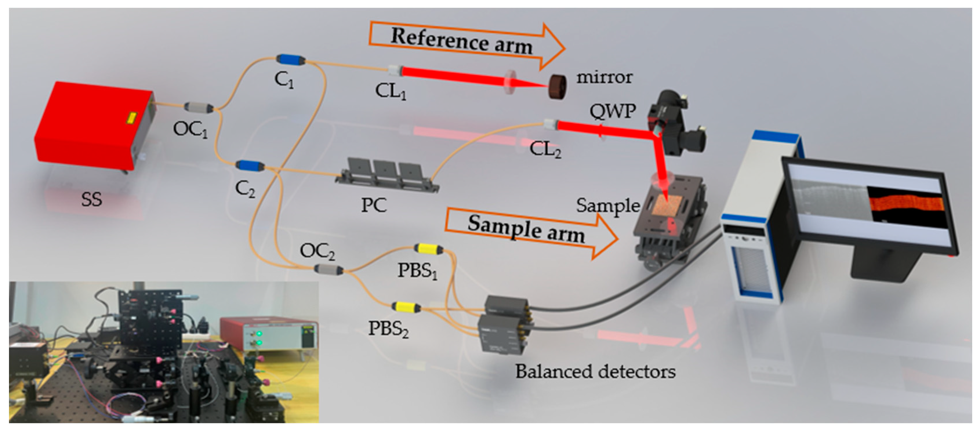
2.1. System Setup of Fiber-Based Polarization Sensitive Optical Coherence Tomography

A scheme of the PSOCT system is shown in Figure 1. The laser (SL131160, Thorlabs, Bergkirchen, Germany) employed was a MEMS-based swept source with a central wavelength of 1310 nm, a spectral bandwidth of 90 nm, a repetition frequency of 100 kHz, and an output power of 25 mW. The light from the laser is split into the reference arm and sample arm by a 20:80 optical coupler (OC1). In the reference arm, the light from port2 of the circulator (C1) sequentially passes through a collimator (CL1), an achromatic lens, and a mirror. The achromatic lens (AC254-050-C, Thorlabs, Germany) uses glasses of two different refractive indices to cancel chromatic aberrations, which can achieve a tighter focus and superior off-axis performance. The reflected reference light back from the mirror finally delivers to a 50:50 optical coupler (OC2) with port3 of the C1. In the sample arm, the light from port2 of the circulator (C2) sequentially passes through a polarization controller, a collimator (CL2), a quarter-wave plate (QWP), a pair of galvo scanners (GVSM002-EC, Thorlabs, Germany), and an achromatic lens before finally arriving to the sample. The sample light backscattered from the tissue also follows its original path back and delivers to a 50:50 optical coupler (OC2) with port3 of the C2. In the detection part, both the s-polarized and y-polarized interference lights from the sample are obtained using two fiber-based polarizing beam separators (PBSs) and two balanced detectors (PDB480C-AC, Thorlabs, Germany). These two interference signals were collected using Channel A and Channel B of a high-speed acquisition card (ATS9371—12 bit, Alazar, Pointe-Claire, QC, Canada).
The system utilizes a swept-source light with a central wavelength of 1310 nm and a full optical bandwidth of 100 nm. The axial resolution of the system can be expressed as z = 2 ln 2 π λ 0 2 λ , where λ 0 represents the central wavelength of the light source, and λ represents the spectral bandwidth of the light source. Therefore, the axial resolution of this system can reach 7.55 μm. The lateral resolution is also influenced by the beam diameter at the sample arm and the achromatic lens focal length, which can be expressed as x = 4 λ 0 f π d . There is an inverse relationship between lateral resolution and axial resolution. In this system, the beam diameter is 2.04 mm, and after passing through a chromatic aberration lens with a focal length of 50 mm, the lateral resolution of the system can be calculated as 40 μm. The maximum imaging depth of the system is approximately 8 mm.
The key point of PSOCT is obtaining a circularly polarized light incident to the sample. PSOCT achieves distinct contrast within samples by observing alterations in the polarization state of backscattered light, resulting from interactions between light and tissues within the sample. A circularly polarized beam exhibits particular sensitivity to birefringent properties.
The imaging process of the sample arm on the in vitro biological sample is shown in Figure 2. The two-dimensional galvo scanners consist of two mirrors in different directions, x and y. The driving voltage of the galvanometer is controlled by a motion control card (PCI6221, National Instruments, Austin, TX, USA), which can be rotated at any angle on the x- and y-axes to change the position of the focus to achieve a lateral and longitudinal scanning of the sample. A set of A-lines is collected at each focus position, and a lateral scan can be completed by rotating only the x-axis. Finally, calculated using the Matlab 2019 complete algorithm, reflectivity, and phase retardation, a picture of a sample PSOCT depth profile is obtained. All of these samples contained abundant tissue with birefringent properties, and the slice thickness was larger than the maximum imaging depth of the system, 8 mm.

2.2. Principle of Numerical Correction Method for Perfect Circularly Polarized Light

The polarization state of a light beam can be represented using the Jones vector. According to Jones matrix theory, any polarization state of light can be represented as the superposition of components along two orthogonal directions:
E = A x A y e i δ
where δ represents the phase difference of E x with E y . The polarization state of linearly polarized light is expressed as follows:
E = cos θ sin θ
A 2 × 2 complex matrix can be used to express the action of a quarter wave plate on a beam as follows:
M Q W P = cos 2 θ + i sin 2 θ sin θ cos θ ( 1 i ) sin θ cos θ ( 1 i ) sin 2 θ + i cos 2 θ
Consequently, the optical system can be systematically traversed using Jones matrices. When the direction of the polarization of linearly polarized light makes an angle of 45° with the direction of the optical axis of the QWP, it can be given as
E θ = 45 = 1 2 1 1
M Q W P θ = 0 = 1 0 0 i
Obtaining the Jones vector of a beam passing through a wave plate involves multiplying the incident beam by the Jones matrix of the wave plate. After passing through an optical element, the change in the polarization state of light is given by E o u t = E i n E 0 . In the reference arm, a mirror reflects a beam passing through an achromatic lens without changing its polarization state. In the sample arm, before reaching the sample, the beam sequentially passes through a polarization controller, a collimator, a QWP, and chromatic aberration lens. The incident light can be transformed into circularly polarized light by adjusting the polarization axis of the incident linearly polarized beam to be oriented using the polarization controller. The incident light represented in the sample arm can be expressed as follows:
E 1 = M Q W P θ = 0 E θ = 45 = 1 2 1 i
This represents a circularly polarized beam. The expression for the returned light from the entire reference arm that carries the sample information is given as follows:
E s = M Q W P θ = 0 M s M s M Q W P θ = 0 E θ = 45
Here, M s ( δ , θ ) is the polarization state change induced by the sample. This explains how the system polarization properties influence the detected fringes. From the known polarization state of the incident light at the sample, one can extract information about the birefringence of the sample.
The imaging method based on the Hilbert transform was used to obtain the reflectivity and birefringence images of the sample and apply the correction method mentioned above [29]. The interference light is divided into orthogonal components ( I 1 , I 2 ) by a polarizing beam separator. I 1 represents the horizontal polarization state, and I 2 represents the vertical polarization state. The interference light is then collected by the detectors. The interference effect of two beams depends on the phase difference. Hence, the intensity of the light detected by a detector can be represented as follows:
I = I 1 + I 2 + 2 I 1 I 2 cos δ
The detected intensity recorded at the depth position z0, Ik(z), is expressed as follows:
I k ( z ) = I r , k + I s , k + 2 I r , k I s , k γ ( z z 0 ) cos ( δ k )
where Ir,k is the intensity of the reference arm, and Is,k represents the intensity of the sample arm. The system configuration uses a polarization sensitive two-channel detection unit, where k assumes values 1 and 2. The modulus of the complex degree of coherence between the sample and reference arms, ranging from 0 to 1, is represented by γ ( z z 0 ) .
Considering the use of the Hilbert transform to handle the above-mentioned interference signal Ik(z), we have the following [30]:
I k ( z ) + i H I k ( z ) = A k ( z ) exp i δ k ( z )
In the demodulation of birefringence information from the sample, it is assumed that the incident light is perfectly circularly polarized. In practical measurements, any deviation from perfect circular polarization is considered polarization information from the sample. A QWP can be used to convert linearly polarized light to circularly polarized light. This requires an angle of 45° between the fast and slow axis directions of the wave plate and the polarization direction of the linearly polarized light. When this angle deviates by 45°, linearly polarized light passes through the QWP and becomes elliptically polarized light. In order to verify that the deviation of circularly polarized light will affect the imaging effect, the imaging was carried out by controlling circularly polarized light as the variable. As shown in Figure 3, when the angle reading of the QWP in the PSOCT system built in this study was 120°, the incident light was closest to perfect circularly polarized light. Depth profiles present depth information in an A-line with depth as the horizontal coordinate and intensity as the vertical coordinate. One of them is used here as an illustration to compare its SNR before and after calibration. A higher SNR generally means that the signal is stronger relative to the noise, thus demonstrating the increased imaging sensitivity. The samples were thinly sliced chicken breasts. According to the imaging and depth profile information, the reflected light collected was mainly concentrated near the depth of 200, and the depth of more than 500 is noise. Therefore, it is necessary to calibrate the circularly polarized light to ensure accurate measurements.
To address this issue, a simple numerical method for correcting the magnitudes of s-polarized and p-polarized light from two detectors is proposed. As shown in Figure 4a, to obtain circularly polarized light, a numerical correction was applied to the field map. The inverse Fourier transform of the fringes generated the complex field and expressed vectors IA and IB in the complex plane. IA and IB are orthogonal to each other and have the same order of magnitude when the incident light is circularly polarized. In order to satisfy all requirements, IA and IB must be reconstructed before quadrature assembling. First, IA and IB are normalized by dividing each by its own absolute value, leading to vectors IA and IB, both with a magnitude of 1. The new vectors I′A and I′B are obtained using the following:
I A = I A + I B
I B = I A I B
These newly constructed vectors I′A and I′B clearly meet the criteria of orthogonality and equality and serve as the correction field vectors. The imaging of perfect circularly polarized light is obtained using the newly constructed vectors I′A and I′B as the complex field of the interference fringes acquired.
According to the theory given above, sample reflectivity R and phase retardation δ can be extracted from the complex function using the following expressions:
R ( z ) = A 1 ( z ) 2 + A 2 ( z ) 2
δ ( z ) = arctan A 2 ( z ) A 1 ( z )
Before reaching the sample, the beam in the sample arm undergoes QWP modulation to achieve circular polarization. As depicted in Figure 2b, in the context of observation within a fixed plane perpendicular to the optical axis, the circularly polarized light vector exhibits a constant magnitude of rotation, forming a circular trajectory. When the polarization state of light passing through the QWP is oriented at a 45° angle relative to the plate, circular polarization is achieved. However, in practical optical systems, the propagation direction of light along the optical axis is difficult to ascertain, necessitating a numerical calibration process to compensate for such uncertainties.

3. Results and Discussion

Scans were performed on chicken breast, pork, and beef samples to demonstrate the improvement in imaging depth and resolution achieved by the system. The experiments used a collimated beam diameter of 2.04 mm, with a power of 10–15 mW applied to the samples. Every cross-sectional image contained 1000 A-lines, as shown in Figure 5. A significant advantage of PSOCT, in addition to the basic structural information provided by reflectivity imaging, is its ability to capture phase retardation imaging, including birefringence information. However, the original OCT reflectivity image shows only the structural details of the sample, and the imaging quality is less clear. Based on phase retardation, the birefringence image additionally demonstrates the birefringent characteristics, enabling the observation of distinct muscle fiber structures within the sample with evident layering. Figure 5a shows the imaging effect of thin layer slices of isolated chicken breast. (a1) Reflectance imaging can visualize the surface of the sample and the internal structure of muscle fiber. However, the imaging results are fuzzy, and the stratification structure is not clear. Because chicken breasts are mainly composed of fibrous tissue and have strong birefringent properties, the birefringence image of (a3) appears in multiple layers. These axial color lacerations are phase delay maps obtained through data processing, which reflect only the birefringence characteristics of the sample itself and do not represent the actual structural alterations inside the sample. When examining a tissue sample of muscle pork ex vivo, various parts of the sample tissue exhibit distinguishable levels of birefringence. The pork samples were scanned across the fat and lean areas. In Figure 5(b3), the birefringence imaging can be divided into approximately quadruples from left to right. One-quarter and three-quarters of the color are relatively consistent, corresponding to the white part of the pork sample; approximately three panchromatic oscillations occur in the two rightmost quarters, which indicate a phase shift of 360°, corresponding to the red portion of the sample. The variation in refractive indices among various tissue samples was validated by this observation. Simultaneously, a comparison between the Figure 5 (3) and (4) images reveals the noticeable effects of the correction method. This comparison highlights the significant effects of the correction technique. Building on this, Figure 5 (3) and (4) was generated using a calibration algorithm applied to the 4096 × 1000 data used for imaging.
The depth profiles of the intensity signals of a single reflector in the birefringence image before and after calibration were measured to quantitatively analyze the extent of improvement in the images due to the numerical calibration algorithm for circularly polarized light. Each image in Figure 5 contains 1000 such A-lines. The image is mainly presented around depth positions of 100–300. After a depth position of 450, it is beyond the imaging range of the system, and the intensity here is the noise intensity.
As illustrated in Figure 6, the orange curve depicts the signal intensity before calibration, whereas the blue curve shows the signal intensity after calibration. The orange curve shows a slope from 0 to 100 depths, which may be caused by the light not passing through the center of the QWP during scanning. The imaging sensitivities of chicken breast, pork, and beef were enhanced by approximately 20 dB after applying the proposed numerical calibration for circularly polarized light. This improvement is not incidental; B-scans of the samples were conducted, resulting in 500 images each for both reflectivity and birefringence before and after calibration, all demonstrating substantial improvements. Consequently, the imaging sensitivity of the PSOCT system was enhanced through this numerical calibration method for circularly polarized light.
Meanwhile, tissue samples of beef and pork were used to evaluate the imaging capabilities of the Hilbert transform and PSOCT system, resulting in the acquisition of 500 consecutive depth profile images. Numerical calibration was then applied to 1000 birefringence images. These 500 images were sequentially assembled, yielding 3D reconstructions of beef and pork, as illustrated in Figure 7. The side-by-side assembly of the images demonstrates a continuous layered structure. The observable continuity and integrity of the muscle fiber structures in the samples validate the efficacy and accuracy of the proposed circular polarization calibration method and our PSOCT system.

4. Conclusions

In this paper, a simple approach using circularly polarized light to enhance the imaging effect of PSOCT was proposed. This approach uses the inverse Fourier transform of the interference fringe to obtain a complex field and numerically calibrates it to make the incident light perfectly circularly polarized. Reflectivity and birefringence images were obtained using the Hilbert transform-based method. The effects of improving the image of birefringence in chicken breast, pork, and beef tissue were demonstrated. The findings of this study indicate a significant improvement in the imaging of birefringence. This approach provides a practical solution for enhancing PSOCT without requiring significant system modifications, making it a cost-effective and accessible approach for improving imaging capabilities.
PSOCT can enhance image contrast and show more of the samples’ internal microscopic structure. PSOCT has been applied in many clinical fields and has good development prospects. The proposed calibration algorithm for circularly polarized light has low complexity and a negligible effect on imaging time. The improvement of the imaging SNR may be favorable for the imaging of clinical PSOCT systems. In the proposed setup, the circularly polarized light of PSOCT is created in free space through a QWP, which requires that the sample be in vitro. Nevertheless, the circularly polarized light calibration method proposed in this paper can be applied to all conventional PSOCT systems.

Supplementary Materials

The following supporting information can be downloaded at https://www.mdpi.com/article/10.3390/app14062525/s1: Video S1: A 3D rotation video of pork sample reconstruction.

Author Contributions

Methodology, S.L.; software, L.H.; validation, S.L.; writing—original draft, S.L.; writing—review and editing, J.C. All authors have read and agreed to the published version of the manuscript.

Funding

This research was funded by the National Natural Science Foundation of China, grant number 62205093, and Hainan Province Science and Technology Special Fund, grant number ZDYF2023SHFZ135.

Institutional Review Board Statement

Not applicable.

Informed Consent Statement

Not applicable.

Data Availability Statement

The data used to support the findings of this study are available upon request from the corresponding author.

Conflicts of Interest

The authors declare no conflicts of interest.

References

  1. Huang, D.; Swanson, E.A.; Lin, C.P.; Schuman, J.S.; Stinson, W.G.; Chang, W.; Hee, M.R.; Flotte, T.; Gregory, K.; Puliafito, C.A.; et al. Optical coherence tomography. Science 1991, 254, 1178–1181. [Google Scholar] [CrossRef] [PubMed]
  2. Li, Y.; Shen, F.; Hu, L.; Lang, Z.; Liu, Q.; Cai, F.; Fu, L. A Stare-Down Video-Rate High-Throughput Hyperspectral Imaging System and Its Applications in Biological Sample Sensing. IEEE Sens. J. 2023, 23, 23629–23637. [Google Scholar] [CrossRef]
  3. Tearney, G.J.; Brezinski, M.E.; Bouma, B.E.; Boppart, S.A.; Pitris, C.; Southern, J.F.; Fujimoto, J.G. In Vivo Endoscopic Optical Biopsy with Optical Coherence Tomography. Science 1997, 276, 2037–2039. [Google Scholar] [CrossRef] [PubMed]
  4. Leggett, C.L.; Gorospe, E.C.; Chan, D.K.; Muppa, P.; Owens, V.; Smyrk, T.C.; Anderson, M.; Lutzke, L.S.; Tearney, G.; Wang, K.K. Comparative diagnostic performance of volumetric laser endomicroscopy and confocal laser endomicroscopy in the detection of dysplasia associated with Barrett’s esophagus. Gastrointest. Endosc. 2016, 83, 880–888.e882. [Google Scholar] [CrossRef] [PubMed]
  5. Holland, A.J.; Martin, H.C.; Cass, D.T. Laser Doppler imaging prediction of burn wound outcome in children. Burns 2002, 28, 11–17. [Google Scholar] [CrossRef]
  6. Jeng, J.C.; Bridgeman, A.; Shivnan, L.; Thornton, P.M.; Alam, H.; Clarke, T.J.; Jablonski, K.A.; Jordan, M.H. Laser Doppler imaging determines need for excision and grafting in advance of clinical judgment: A prospective blinded trial. Burns 2003, 29, 665–670. [Google Scholar] [CrossRef] [PubMed]
  7. Spaide, R.F.; Fujimoto, J.G.; Waheed, N.K.; Sadda, S.R.; Staurenghi, G. Optical coherence tomography angiography. Prog. Retin. Eye Res. 2018, 64, 1–55. [Google Scholar] [CrossRef]
  8. Laíns, I.; Wang, J.C.; Cui, Y.; Katz, R.; Vingopoulos, F.; Staurenghi, G.; Vavvas, D.G.; Miller, J.W.; Miller, J.B. Retinal applications of swept source optical coherence tomography (OCT) and optical coherence tomography angiography (OCTA). Prog. Retin. Eye Res. 2021, 84, 100951. [Google Scholar] [CrossRef]
  9. Larin, K.V.; Sampson, D.D. Optical coherence elastography—OCT at work in tissue biomechanics. Biomed. Opt. Express 2017, 8, 1172–1202. [Google Scholar] [CrossRef]
  10. Tang, P.; Wang, R.K. Polarization sensitive optical coherence tomography for imaging microvascular information within living tissue without polarization-induced artifacts. Biomed. Opt. Express 2020, 11, 6379–6388. [Google Scholar] [CrossRef]
  11. Eugui, P.; Harper, D.J.; Lichtenegger, A.; Augustin, M.; Merkle, C.W.; Woehrer, A.; Hitzenberger, C.K.; Baumann, B. Polarization-sensitive imaging with simultaneous bright- and dark-field optical coherence tomography. Opt. Lett. 2019, 44, 4040–4043. [Google Scholar] [CrossRef]
  12. Yao, G.; Duan, D. High-resolution 3D tractography of fibrous tissue based on polarization-sensitive optical coherence tomography. Exp. Biol. Med. 2020, 245, 273–281. [Google Scholar] [CrossRef] [PubMed]
  13. Mariottoni, E.B.; Jammal, A.A.; Urata, C.N.; Berchuck, S.I.; Thompson, A.C.; Estrela, T.; Medeiros, F.A. Quantification of Retinal Nerve Fibre Layer Thickness on Optical Coherence Tomography with a Deep Learning Segmentation-Free Approach. Sci. Rep. 2020, 10, 402. [Google Scholar] [CrossRef] [PubMed]
  14. Fialová, S.; Augustin, M.; Fischak, C.; Schmetterer, L.; Handschuh, S.; Glösmann, M.; Pircher, M.; Hitzenberger, C.K.; Baumann, B. Posterior rat eye during acute intraocular pressure elevation studied using polarization sensitive optical coherence tomography. Biomed. Opt. Express 2017, 8, 298–314. [Google Scholar] [CrossRef]
  15. Hee, M.R.; Huang, D.; Swanson, E.A.; Fujimoto, J.G. Polarization-sensitive low-coherence reflectometer for birefringence characterization and ranging. J. Opt. Soc. Am. B 1992, 9, 903–908. [Google Scholar] [CrossRef]
  16. Wang, H.; Akkin, T.; Magnain, C.; Wang, R.; Dubb, J.; Kostis, W.J.; Yaseen, M.A.; Cramer, A.; Sakadžić, S.; Boas, D. Polarization sensitive optical coherence microscopy for brain imaging. Opt. Lett. 2016, 41, 2213–2216. [Google Scholar] [CrossRef]
  17. Lin, H.; Kao, M.C.; Lai, C.M.; Huang, J.C.; Kuo, W.C. All fiber optics circular-state swept source polarization-sensitive optical coherence tomography. J. Biomed. Opt. 2014, 19, 21110. [Google Scholar] [CrossRef]
  18. Al-Qaisi, M.K.; Akkin, T. Polarization-sensitive optical coherence tomography based on polarization-maintaining fibers and frequency multiplexing. Opt. Express 2008, 16, 13032–13041. [Google Scholar] [CrossRef]
  19. Trasischker, W.; Zotter, S.; Torzicky, T.; Baumann, B.; Haindl, R.; Pircher, M.; Hitzenberger, C.K. Single input state polarization sensitive swept source optical coherence tomography based on an all single mode fiber interferometer. Biomed. Opt. Express 2014, 5, 2798–2809. [Google Scholar] [CrossRef]
  20. Tang, P.; Kirby, M.A.; Le, N.; Li, Y.; Zeinstra, N.; Lu, G.N.; Murry, C.E.; Zheng, Y.; Wang, R.K.J.L. Polarization sensitive optical coherence tomography with single input for imaging depth-resolved collagen organizations. Sci. Appl. 2021, 10, 237. [Google Scholar] [CrossRef]
  21. Kiseleva, E.; Kirillin, M.; Feldchtein, F.; Vitkin, A.; Sergeeva, E.; Zagaynova, E.; Streltzova, O.; Shakhov, B.; Gubarkova, E.; Gladkova, N. Differential diagnosis of human bladder mucosa pathologies in vivo with cross-polarization optical coherence tomography. Biomed. Opt. Express 2015, 6, 1464–1476. [Google Scholar] [CrossRef] [PubMed]
  22. Gubarkova, E.V.; Kirillin, M.Y.; Dudenkova, V.V.; Timashev, P.S.; Kotova, S.L.; Kiseleva, E.B.; Timofeeva, L.B.; Belkova, G.V.; Solovieva, A.B.; Moiseev, A.A.; et al. Quantitative evaluation of atherosclerotic plaques using cross-polarization optical coherence tomography, nonlinear, and atomic force microscopy. J. Biomed. Opt. 2016, 21, 126010. [Google Scholar] [CrossRef]
  23. Li, E.; Makita, S.; Hong, Y.-J.; Kasaragod, D.; Yasuno, Y. Three-dimensional multi-contrast imaging of in vivo human skin by Jones matrix optical coherence tomography. Biomed. Opt. Express 2017, 8, 1290–1305. [Google Scholar] [CrossRef]
  24. Xiong, Q.; Wang, N.; Liu, X.; Chen, S.; Braganza, C.S.; Bouma, B.E.; Liu, L.; Villiger, M. Constrained polarization evolution simplifies depth-resolved retardation measurements with polarization-sensitive optical coherence tomography. Biomed. Opt. Express 2019, 10, 5207–5222. [Google Scholar] [CrossRef] [PubMed]
  25. Adams, D.C.; Szabari, M.V.; Lagares, D.; Mccrossan, A.F.; Hariri, L.P.; Tager, A.M.; Suter, M.J. Assessing the progression of systemic sclerosis by monitoring the tissue optic axis using PS-OCT. Sci. Rep. 2020, 10, 2561. [Google Scholar] [CrossRef]
  26. Braaf, B.; Vermeer, K.A.; de Groot, M.; Vienola, K.V.; de Boer, J.F. Fiber-based polarization-sensitive OCT of the human retina with correction of system polarization distortions. Biomed. Opt. Express 2014, 5, 2736–2758. [Google Scholar] [CrossRef] [PubMed]
  27. Lippok, N.; Villiger, M.; Jun, C.; Bouma, B. Single input state, single-mode fiber-based polarization-sensitive optical frequency domain imaging by eigenpolarization referencing. Opt. Lett. 2015, 40, 2025–2028. [Google Scholar] [CrossRef]
  28. Liu, X.; Jiang, L.; Ke, M.; Schmetterer, L.; Barathi, V.A. Using image data to numerically correct the jitter in polarization depth encoding PS-OCT. Opt. Lett. 2021, 46, 1692–1695. [Google Scholar] [CrossRef]
  29. Zhao, Y.; Chen, Z.; Saxer, C.; Xiang, S.; de Boer, J.F.; Nelson, J.S. Phase-resolved optical coherence tomography and optical Doppler tomography for imaging blood flow in human skin with fast scanning speed and high velocity sensitivity. Opt. Lett. 2000, 25, 114–116. [Google Scholar] [CrossRef]
  30. Nettelblad, H.; Thuomas, K.Å.; Sjöberg, F. Magnetic resonance imaging: A new diagnostic aid in the care of high-voltage electrical burns. Burns 1996, 22, 117–119. [Google Scholar] [CrossRef]
Figure 1. Scheme of polarization sensitive optical coherence tomography. SS: swept source; OC1: 20:80 optical coupler; OC2: 50:50 optical coupler; C1, C2: circulator; PC: polarization controller; PBS1, PBS1: polarizing beam separators; QWP: quarter-wave plate; CL1, CL2: collimator.
Applsci 14 02525 g001
Figure 2. (a) Galvo scanners in the sample arm; (b) the thin slices of in vitro biological samples. From left to right is the chicken breast, pork, and beef.
Applsci 14 02525 g002
Figure 3. Depth profiles of a single reflector with different angles of the QWP. (a) The angle of the QWP is 105°; (b) The angle of the QWP is 120°; (c) The angle of the QWP is 135°.
Applsci 14 02525 g003
Figure 4. (a) Numerical correction procedure for an imperfect circularly polarized reference; (b) image of the polarization composition of the beam obtained by the sample arm before reaching the sample.
Applsci 14 02525 g004
Figure 5. PSOCT images recorded in vitro. The rows from top to bottom show the chicken breast (a), pork (b), and beef (c) in vitro sample imaging. (1,2) (the first two columns) are reflectance imaging. (3,4) (the last two columns) are birefringence imaging. (1,3) show the imaging before calibration, and (2,4) show the imaging after calibration.
Applsci 14 02525 g005
Figure 6. Depth profiles of a single reflector (blue curves: corrected, orange: uncorrected). (a) Chicken breast; (b) pork; (c) beef.
Applsci 14 02525 g006
Figure 7. (a) A 3D rendering of a beef sample; (b) a 3D rendering of a pork sample. Magnified views of the green boxes represent the 150th and 350th PSOCT birefringence images that compose them. (A 3D rotation video of pork sample reconstruction is detailed in Supplementary Materials).
Applsci 14 02525 g007
Disclaimer/Publisher’s Note: The statements, opinions and data contained in all publications are solely those of the individual author(s) and contributor(s) and not of MDPI and/or the editor(s). MDPI and/or the editor(s) disclaim responsibility for any injury to people or property resulting from any ideas, methods, instructions or products referred to in the content.

