Article

Design and Numerical Study of Induction-Heating Graphitization Furnace Based on Graphene Coils

1
Guangdong Provincial Key Laboratory of Thermal Management Engineering & Materials, National-Local Joint Engineering Laboratory of Functional Carbon Materials, Shenzhen 518055, China
2
Shenzhen Geim Graphene Center, Institute of Materials Research, Tsinghua Shenzhen International Graduate School, Shenzhen 518055, China
*
Author to whom correspondence should be addressed.
Appl. Sci. 2024, 14(6), 2528; https://doi.org/10.3390/app14062528
Submission received: 15 February 2024 / Revised: 5 March 2024 / Accepted: 7 March 2024 / Published: 17 March 2024
(This article belongs to the Section Applied Thermal Engineering)

Abstract

:
Induction-heating graphitization furnaces are widely used to produce high-purity graphite products due to their high heating rate, high-limit temperatures, safety, cleanliness, and precise control. However, the existing induction-heating systems based on copper coils have limited energy efficiency. This paper proposes a new induction-heating graphitization furnace based on graphene coils. Due to the excellent high-temperature resistance of the macroscopic graphene material, the coil can be placed closer to the graphite heater, which improves the electromagnetic efficiency; the coil itself does not need to pass cooling water, which reduces the heat loss of the furnace and ultimately results in a higher energy efficiency of the induction furnace. In this paper, a numerical model of the induction-heating process is established and verified, the temperature-field and electromagnetic-field distributions of the heating process are analyzed by using the model, and the energy balance calculations are performed for the original furnace and the new furnace. Through a comparison, it was found that the new furnace possesses an electromagnetic efficiency of 84.87% and a thermal efficiency of 20.82%, and it can reduce the energy consumption by 33.34%, compared with the original furnace. In addition, the influence of the coil parameters on the performance of the induction furnace is discussed. By changing the coil conductivity, the induction furnace can achieve an energy efficiency of 17.76%–18.11%. This study provides new ideas for the application of macroscopic graphene materials in high-temperature induction heating.

1. Introduction

Graphitization is the process of converting initially non-graphitic carbon into graphitic carbon after high-temperature heat treatment [1]. Graphitized carbon materials have excellent thermal conductivity, electrical conductivity, and chemical stability [2], and they are indispensable in the chemical, metallurgical, automotive, and electronic industries. Graphitization requires heating temperatures typically up to 2800 °C or higher, which is an energy-intensive process requiring 3–8 MWh per ton of graphite product produced [3], with the energy consumption accounting for more than 50% of the total cost [4]. Therefore, there are significant environmental and economic incentives to reduce the energy consumption.
Graphitization furnaces are basic equipment in the carbon industry, and they can be classified based on the heating method used, such as Acheson furnaces [5], lengthwise furnaces [6], and induction-heating graphitization furnaces (IHGFs) [7]. The Acheson furnace utilizes the Joule heating of resistive materials to indirectly heat and graphitize baked products. Its design is simple, robust, and easy to maintain, making it widely used in carbon plants. However, it has problems with low energy efficiency, uneven heating, and long production cycles [8,9]. The use of induction-heating technology in IHGFs is nowadays chosen in many industrial, domestic, and medical applications due to its high heating rate, high-limit temperatures, flexible furnace chamber layout, safety, cleanliness, and precise control [10]. The induction-heating system is the central component of the IHGF. It comprises an alternating-current (AC) power supply, an induction coil, and a heater. The AC power supply delivers the alternating current to the induction coil, which generates an alternating magnetic field. The heater, exposed to the magnetic-field radiation, is rapidly heated by the ohmic heating of eddy currents. The induction coil is a crucial component of the induction-heating system, as it transmits induced electrical energy, directly impacting the heating rate and efficiency.
The conductors used for induction coils usually play a key role in the design of the induction coils, and copper conductors are now widely used due to their excellent high electrical conductivity and moderate cost. During the operation of an induction furnace, the copper coils carrying the alternating current (AC) generate heat due to AC losses (coil losses) [11], and, in order to prevent heat buildup and coils overheating, a common industrial practice is to pass cooling water inside the copper coils. The cooling water absorbs the heat generated by the coil losses as well as the heat conducted from the heater and converts itself into warm water of 40–50 °C, which has a very low industrial use value. This process causes a large amount of energy waste [12]. For induction-heating furnaces, the energy loss due to cooling water is about 70% of the total energy loss [13].
The energy efficiency of an induction furnace is the product of its electrical efficiency (ηd) and thermal efficiency (ηr). Refs. [14,15,16] show that the electrical efficiency is related to the distance between the induction coil and heater, the number of turns of the coil, the depth of the current penetration, etc. The thermal efficiency mainly depends on the insulation performance of the induction furnace, which is related to the selection of the furnace lining material, the thickness of the insulation layer, and so on. The induction coil structure based on copper pipes plus cooling water occasionally leads to a contradiction between the electrical efficiency and thermal efficiency: increasing the thickness of the insulation layer is conducive to improving the thermal efficiency, but the increase in the coupling distance between the coil and the heater leads to a decrease in the electrical efficiency [17]. The heater of an IHGF has a temperature of more than 2000 °C in the later stages of heating, which greatly increases the heat dissipation. In order to improve the insulation of the furnace, it is necessary to increase the thickness of the insulation layer, sacrificing some of the electrical efficiency.
This paper proposes a new idea to improve the energy efficiency by manufacturing coils using conductor materials with excellent high-temperature performances. The coil is placed inside the insulation layer next to the heater to achieve higher electrical efficiency; the coil does not need internal cooling water during operation but uses the heat generated by the coil losses for insulation, thereby improving the thermal efficiency. This idea combines the electrical and thermal efficiencies, resulting in the very high energy efficiency of the induction furnace, and it is also of great significance for energy saving in other high-temperature-heating fields, such as ceramsite sintering [18,19,20].
The triple-phase point of carbon is 3727 °C [21], and graphitized carbon materials generally exhibit good high-temperature performances and excellent conductivities. Single-layer graphitic graphene, for instance, has a conductivity as high as 1 × 10⁸ S/m. In recent years, numerous studies have attempted to transfer the microscopic properties of graphene to the macroscopic scale. This class of materials includes graphene-based conductor materials (GCMs), such as graphene films [22,23] and fibers [24,25]. Zhang et al. [26] utilized a nitrogen-doping method to produce highly ordered crystalline graphene films with a conductivity of up to 2.0 × 10⁶ S/m and a thickness of 10 μm. Zhang et al. [27] created an ultra-thick graphene film with a conductivity of 6.91 × 10⁵ S/m and a thickness of 200 μm through the self-fusion property of graphene oxide sheets. Graphene fibers also exhibit excellent mechanical and electrical properties, and the conductivity of graphene fibers after high-temperature annealing can be up to 0.8~2.2 × 10⁶ S/m [28,29,30]. High-performance graphene fibers can be used as high-strength cables [25,31,32], flexible supercapacitors [33,34], or other electronic devices. The conductivity of macroscopic graphene materials is continuously making breakthroughs and showing potential applications in electrical engineering.
The previous discussion highlighted the ability of graphene-based conductor materials to overcome the limitations imposed by copper. This paper describes a novel induction-heating system for IHGFs that utilizes macroscopic graphene materials as coils with impermeable internal cooling water that are placed inside an insulating layer to improve the energy efficiency. In this paper, the energy efficiencies, temperature fields, and electromagnetic fields of the new furnace and original furnace are investigated by numerical simulations. The energy efficiency potential of the new furnace is comparatively analyzed, and the impact of the coil parameters is discussed.

2. Numerical Model

2.1. Structure of Induction-Heating Graphitization Furnace

This paper presents a study on an original IHGF, as shown in Figure 1a. The furnace has a radius of 0.9 m and a height of 2.1 m, and its main components are the furnace shell, coil, graphite heater, and insulation. The vacuum environment of the furnace, with a pressure of less than 0.5 Pa, prevents the oxidation of the graphite heater and charge at high temperatures. The carbon-black and carbon-felt insulation does not react with the graphite heater, even when in contact with it at high temperatures. The copper tube coil is located in the corundum insulation layer, and cooling water with a pressure of 0.2 MPa is passed inside the copper tube. By applying an alternating current with a frequency of 1500 Hz to the coil, eddy currents are induced in the graphite heater. This, in turn, heats the heater through the Joule effect. The temperature at control point A (0, 1.5) was measured throughout the manufacturing process.
The graphene-coil IHGF is shown in Figure 1b. The insulation layer contains a 30 mm radius graphene coil to which an alternating current is applied. The ultra-high-heat performance of the graphene material in a vacuum environment eliminates the need for cooling water to pass through the coil. The heat generated by the coil is used to heat the graphite heater or insulation. Compared to original furnaces, the graphene-coil furnace makes more efficient use of the ohmic heat on the coils, resulting in higher energy efficiency. In addition, the proximity of the graphene coil to the graphite heater ensures higher electrical efficiency.
The furnace charge is made of graphite products, the furnace insulation is made of carbon black and carbon felt, and the furnace wall is made of cement. The specific material parameters were obtained from the literature [35,36,37,38] and are expressed as polynomials or interpolated functions due to the significant variation in the material properties during the heating process. The study simplified the heat transfer process in the furnace by unifying and simplifying the convection, radiation, and heat transfer to solid heat transfer. The material parameters for the graphene coil were chosen based on the macroscopic graphene film prepared by our group. The conductivity of the coil was measured to be 1.1 × 10⁶ S/m using the four-probe method. The parameters of coils are shown in Table 1.

2.2. Mathematical Model

2.2.1. Basic Assumptions

The simulation of an induction graphitizing furnace involves several physical fields with strong coupling. In order to ensure scientific results and reduce the difficulty of model solving, the following simplified assumptions must be formulated for the model:
  • All materials in the model are pure;
  • All materials in the model are isotropic;
  • No consideration is given to mechanical stresses or deformations due to temperature changes;
  • No consideration is given to the phase transition.

2.2.2. Equation of Electromagnetic Field

To accurately calculate the electromagnetic field, a computational domain ten times larger than that of the induction furnace is chosen. Eddy currents are generated during induction heating when the workpiece is subjected to alternating magnetic fields, and the behavior and generation of these fields are controlled by Maxwell’s equations [39]. Solving Maxwell’s equations is the starting point for solving induction-heating problems. In general, Maxwell’s equations can be written as follows:
× H = J + D t
× E = j ω B
· D = ρ e
· B = 0
In these equations, H represents the magnetic-field strength; J represents the current density; E represents the electric-field strength; D represents the electric-flux density; B represents the magnetic-flux density; j represents the complex number j2 = −1; ω represents the angular frequency; ρe represents the charge density; and t represents the time. The constitutive relations are as follows:
B = μ H
D = ϵ E
J = σ E + J e
The magnetic-flux density and electric-field strength can be expressed as follows:
B = × A
E = V × A / t

2.2.3. Equation of Heat Transfer

This study assumes that the induction furnace is a solid heat transfer medium and neglects the effect of the gas flow on the temperature distribution. Heat is transferred through conduction, as described by the partial differential equation for heat transfer:
ρ C T t = x λ T x + y λ T y + z λ T z + Q
The given equation shows the expression for Q, which is the thermopower. The Q is mainly composed of volumetric thermopower generated by the induced eddy currents and losses on the induction coils. The equation includes the following variables: ρ for the density in kg/m3; c for the specific heat in J/(kg·K); λ for the thermal conductivity in W/(m·K); xyz for the right-angle coordinate in meters; T for the absolute temperature in Kelvin; and τ for the time in seconds. The expression for the Q can be written in terms of the current density and conductivity:
Q = | J | 2 σ
To solve the governing equations, boundary conditions must be defined. In particular, at the symmetry axis, the radial gradients of all the dependent variables should be zero. Furthermore, at the outer boundary of the simulation domain, the magnetic vector potential should be zero, and the temperature should be the same as the ambient temperature. Special attention should be paid to the fact that the temperature of the coil and the furnace wall should also be set to the ambient temperature due to the effective cooling by water. If the temperature of the furnace surface is not kept constant, the thermal equilibrium conditions will change:
n · k f T F q r l + n · k a m b T a m b = 0
The notations ‘f’ and ‘amb’ are used to denote ‘furnace’ and ‘ambient’, respectively. In addition, the term ‘qrl’ is used to denote the amount of heat lost by radiation from the surface.

2.3. Numerical Method

In this study, the commercial simulation software COMSOL Multiphysics® 6.1 was used, which involves multiphysics fields with strong coupling that are difficult to solve. A transient study was performed to obtain the analysis results of multiple moments. The calculation period of 20 h was chosen based on the actual process.
To ensure the computational accuracy and smoothness of the large volume, the mesh was refined at the heater and coil, while the rest of the area was coarsened for the mesh division. This accounted for the skin effect, as shown in Figure 2. The grid’s independence was tested by expanding it from 41,840 to 273,435 cells. The comparison results indicate that refining the grid with 112,650 additional cells did not produce any significant changes. Therefore, subsequent calculations were performed using 112,650 cells.

2.4. Model Validation

In this paper, we describe the heating procedure used to heat the copper-coil model in a company’s actual production process. The heating regime consists of three stages: repeated roasting, graphitization temperature control, and completion of graphitization. The heating rate of each stage is specially designed based on the kinetic characteristics of the graphitization process of the charge. The power curve is shown in Figure 3a.
The simulation results for the core temperature were compared with the actual production data, as shown in Figure 3b. The trend and maximum temperature of the experiment were in good agreement with the simulation results, indicating the reliability of the simulation model. Therefore, the proposed model can be used to calculate and analyze the heat transfer in the furnace.

3. Results and Analysis

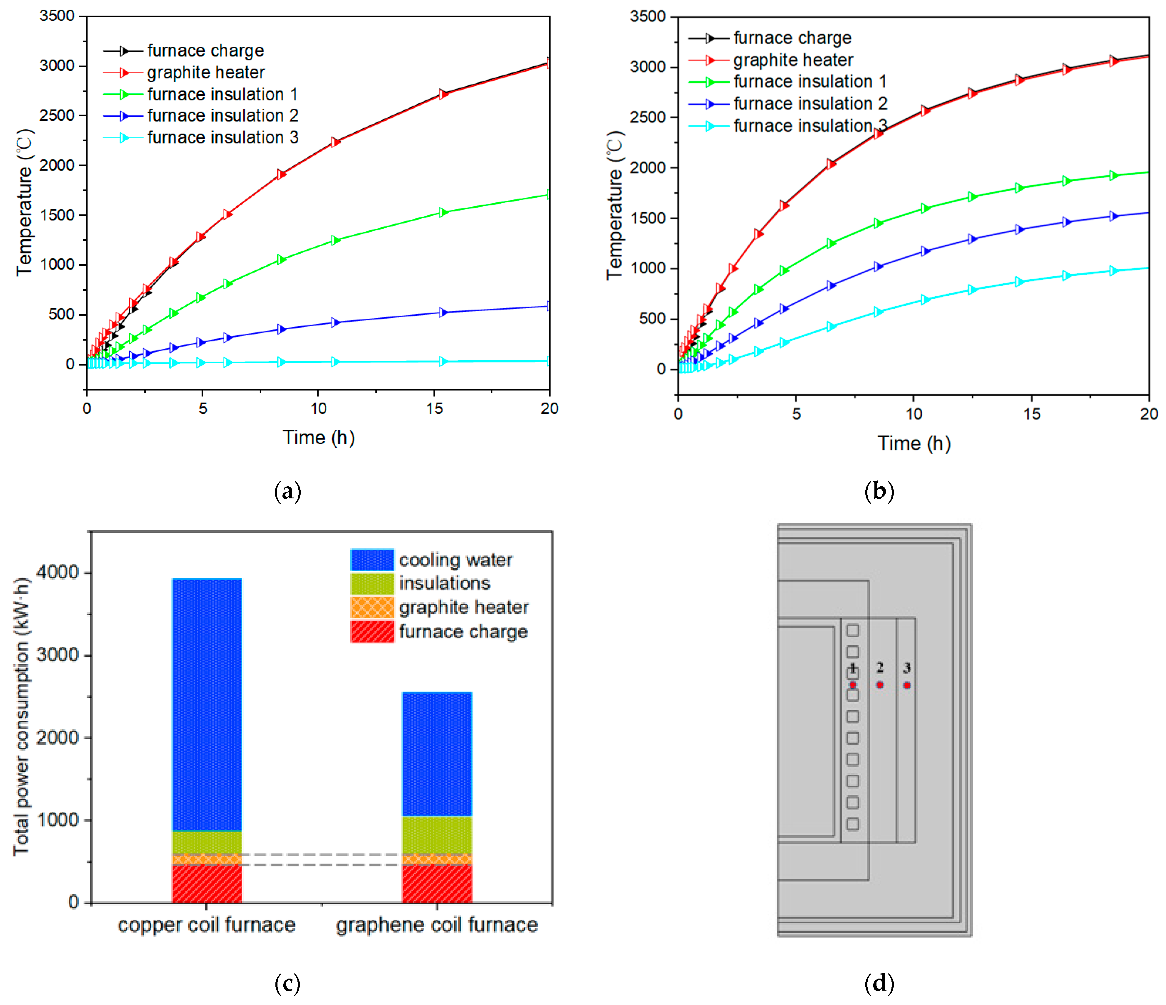
3.1. Comparison of Energy Efficiency

3.1.1. Energy Efficiency Parameters of Induction Furnaces

The energy absorbed by the furnace charge during the heating process can be expressed as follows:
Q f c = T 1 f c T 2 f c m f c · C f c d T
where Cfc, mfc, T1fc, and T2fc represent the specific heat capacity of the charge, the mass, and the temperatures at the beginning and end of heating, respectively. Similarly, other parts of the energy (Qother) can be calculated for the heating.
The energy lost by heat dissipation (Qd) includes the heat dissipated by heat convection, heat conduction, and heat radiation from each component in the heating process. Part of the heat (Qcw) is absorbed by the cooling water, and the rest is dissipated through the furnace wall to the environment (Qe). In this study, the heat transfer in the furnace is simplified to solid heat transfer, and the energy absorbed by the cooling water can be expressed as follows:
Q c w = t c 1 t 2 λ d · S · ( T t T 0 ) d t
where λ is the thermal conductivity of the insulating layer, d is the thickness of the insulating layer, S is the heat dissipation area of the insulating layer, Tt and T0 are the temperature of the furnace charge at the time (t) and the temperature of the cooling water, respectively.
Then, the total energy consumption can be expressed as follows:
Q t o t a l = Q f c + Q o t h e r s + Q d
The thermal energy (Qgh) generated by the load (graphite heater) under the influence of a magnetic field of strength H can be expressed as follows:
Q g h = t c 1 t 2 4 π 2 μ r f · H · L · A d t
where f is the current frequency, L is the heater length, and A is the heater cross-sectional area.
The electrical efficiency (ηe) is defined as follows:
η e = Q g h Q t o t a l
The thermal efficiency (ηt) is defined as follows:
η t = Q f C Q g h
The energy efficiency (η) is the product of the electrical and thermal efficiencies:
η = η e · η t

3.1.2. Energy Efficiency Comparison Experiment

This paper describes a simulation of the heating processes of two furnaces. To facilitate the comparison, we applied different constant powers to the two furnaces and compared the amount of power required to reach the target temperature of 3100 °C after 20 h of heating. The induction furnace with the copper coil has a heating power of 201 kW, while the induction furnace with the graphene coil has a heating power of 135 kW. To study the heating rate, a temperature measurement point is selected inside the furnace. Figure 4a shows the relationship between the temperature and heating time at the selected points for the different types of furnaces. The figure shows that the copper-coil furnace initially heats the charge faster due to its higher heating power. However, around 2000 °C, the heating rate slows down significantly. In contrast, the graphene-coil furnace has a more stable heating rate, and there is no significant decrease in the heating rate in the high-temperature region.
Figure 4b shows the curves of the heat flux versus time at the heater/insulation interfaces for both furnaces. The heat dissipation of the graphene-coil furnace is significantly reduced compared to that of the original furnace. As shown in Equation (14), the graphene-coil furnace has no in-coil cooling water and is further away from the cooling source (T0), so the heat dissipation power is lower for the same temperature difference, which allows it to maintain a higher heating rate in the high-temperature region.
Figure 5a,b show the temperature variation in each part of the two furnaces during the heating process. The energy absorbed by each part during the heating process was calculated, and the energy efficiency performance parameters were derived according to Equation (13); the results are shown in Table 2. In terms of the electrical efficiency, the graphene coil is closer to the heater and the coupling distance between the two is short, which has a higher electrical efficiency compared to the copper coil. In terms of the thermal efficiency, the cold source of the copper-coil furnace is mainly located in the coil (coil cooling water), closer to the heater, while the cold source of the graphene coil is located at the far end of the furnace shell. In addition, the ohmic heat of the graphene coil is also used in the heat insulation of the heater, and thus the insulation performance is better. Taken together, only 12.02% of the coil input energy is absorbed by the heated charge in a conventional copper-coil induction furnace, while the graphene-coil furnace has an energy efficiency of 17.67%. As shown in Figure 5c, to heat the same mass of charge, the energy absorbed by the cooling water in the former furnace is 1506 kWh higher than that in the latter furnace, which has a higher temperature at the end of heating the insulation layer and absorbs 314 kWh more energy.
Due to the advantages in the electrical and thermal efficiencies, the graphene-coil furnace has a higher energy efficiency compared to the copper-coil furnace, and for heating the same mass of charge, the energy consumption of the graphene-coil furnace can be reduced by 33.34%. It can be concluded that the graphene-coil furnace is more efficient than the copper-coil heating furnace in terms of energy utilization.

3.2. Electromagnetic-Field Distribution

The magnetic-flux density and current density distributions of the two furnaces were compared under the same alternating current size. Figure 6a shows that the orientation of the magnetic induction starts above the coil and loops back below it. The distribution patterns of the magnetic-flux density in both furnaces are predominantly concentrated in the region between the heater and the coil. Following the universal current law, there is a uniform decrease in the magnetic-field strength within a helical coil that is inversely proportional to the increasing radius of the coil. As highlighted in Figure 6b, the induction coil of the graphene-coil furnace has an enhanced internal magnetic-field strength due to its closer positioning to the heater. This arrangement allows the graphene-coil furnace to achieve superior electrical efficiency for the same amount of current.
The current is mainly distributed in the charge, graphite heater, and coil. To facilitate the observation, these three parts of the cloud diagram were selected, and the results are shown in Figure 7. Due to the influence of the skin effect, the current densities of the two types of furnaces are the maximum in the inner wall of the coil, followed by the outer wall of the heater, and there is almost no current distribution in the charge. The skin depth is estimated as δ = √(1/(πfσμ0)). For this calculation, the current frequency is f = 1500 Hz, the conductivity of the Cu is σ_Cu = 6.0 × 10⁷ S/m, which gives the skin depth δ_Cu = 1.68 mm for the copper coil, and the conductivity for the graphene is σ_G = 1.1 × 10⁶ S/m, which gives the skin depth δ_G = 12.40 mm for the graphene coil. The figure also shows that the skin effect of the copper coil is more obvious.

3.3. Temperature-Feld Distribution

3.3.1. Initial Heating

Figure 8a,b show the temperature-field distribution during heating for 1 h. At the start of the induction-heating process, the highest-temperature region for the original furnace is at the graphite heater. Heat is transferred from the graphite heater to the charge and thermal insulation. For the graphene-coil furnace, the highest-temperature region occurs at both the heater and the coil, with the temperature slightly higher at the heater. Combined with Figure 8c,d, it is evident that the heat flux at the heater of the graphene-coil furnace is smaller than that at the heater of the copper-coil furnace. This is due to the fact that the heat source of the graphene-coil furnace consists of both the heater and the coil, and the ohmic heat of the coil can be used to insulate the heater during the heating process, resulting in higher energy efficiency compared to the original furnace.

3.3.2. End of Heating

The temperature distributions for both furnaces after heating for 20 h are displayed in Figure 9a,b. The figure shows that the temperature gradient inside the furnace decreases upon completion of heating, and the highest temperatures for both furnace types occur at the heater with H = 1.35 m, with temperatures of 3153 °C and 3147 °C. There is a temperature difference of approximately 47 °C between the center region of the charge and the maximum temperature. It is worth noting that the maximum coil temperature of the graphene-coil furnace is 2561 °C.
As shown in Figure 9b, the temperature distribution along the r-axis is divided into three parts: the furnace charge zone, insulation layers, and other spaces. Due to the high thermal conductivity of the charge, the temperature distribution inside the charge is more uniform, and the temperature of the graphite heater is slightly higher than that of the charge. Inside the insulation layers, the temperature distribution curve along the r-axis takes the form of a concave function. This is due to the fact that, under the condition of a near-steady state in the late stage of heating, the area through which the heat flows from the inside of the insulation to the outside increases with the r, which means that the temperature change becomes smaller and smaller with the distance from the inside, and thus the temperature curve tends to be flat. For the graphene-coil furnace, the temperature gradient inside the insulation is much smaller because the coil losses are used for heat insulation, which explains its lower heat flux at the heater/insulation interface in the later stages of heating.

3.4. Effect of Coil Parameters

The analysis above demonstrates that the graphene-coil IHGF is highly energy efficient. However, a problem arises with the high coil temperature during the latter part of the heating process. As noted in [40], graphite is susceptible to high-temperature vaporization under vacuum conditions, particularly when heated above 2500 °C. This vaporization significantly impacts the device’s lifespan. To achieve the maximum energy efficiency and a lower coil temperature, optimizing the coil parameters is necessary.

3.4.1. Effect of Coil Conductor Conductivity

Given that the electrical conductivity of GCMs is still lower than that of copper, it is important to pay special attention to the coil losses. The ohmic heating of the current can be calculated using Equation (11), which takes into account the skin loss and the neighbor loss of the high-frequency current. The effects of the coil size and conductivity on the coil losses are discussed in this study. The side length of the square coil was varied from 60 mm to 100 mm, while the conductivity of the graphene coil was varied from 1 to 7 × 10⁶ S/m. It is clear from Figure 10a that the coil losses are not uniformly concentrated in the interior of the conductor. For coils of the same cross-sectional area, the area of coil losses decreases as the conductivity of the coil material increases. For the same coil with a conductivity of 1 × 10⁶ S/m, increasing the cross-sectional area shrinks the region of high losses. It should be noted, however, that because the distance between the coils is fixed, the proximity effect is enhanced as the distance between the coils decreases with the increasing coil area. Therefore, increasing the tube radius will reduce the skin effect while increasing the proximity effect.
Figure 10b summarizes the coil losses for different coil conductor conductivities and different coil cross sections. For coils of the same cross-sectional area, the variation in the conductivity of the coil conductor significantly affects the magnitude of the coil loss. When the conductivity of the conductor material is varied from 1 × 10⁶ S/m to 7 × 10⁶ S/m, the total coil loss decreases from 18.13 kW to 6.67 kW for the same magnitude of alternating current (AC), while increasing the cross-sectional area of the coil has no significant effect on the coil loss.
The effect of variations in the coil conductivity on the temperature distribution of induction furnace coils was investigated, as shown in Figure 11. It was observed that as the conductivity of the conductor material increased from 1 × 10⁶ S/m to 7 × 10⁶ S/m, the temperature of the coil decreased from 2561 °C to 2502 °C, and the energy efficiency of the induction furnace improved from 17.76% to 18.11%. This improvement is attributed to the reduction in coil losses as the conductivity of the conductor material increases, which, in turn, reduces self-heating and allows more energy to be used for induction heating, thereby increasing the energy efficiency of the induction furnace. It is evident that increasing the conductivity of the coil materials is beneficial for improving the energy efficiency and durability of induction furnaces.

3.4.2. Effect of Coil Position

Figure 12 shows how the coil’s temperature and the induction furnace’s energy efficiency are influenced by the coil’s distance from the graphite heater, represented by the coil diameter (Φ) ranging from 0.8 m to 1 m. As the Φ increases, the coil-heater gap widens, leading to a notable coil temperature drop after 20 h of heating—from 2561 °C to 1870 °C. Notably, at Φ = 0.85 m, the coil temperature decreases to 2342 °C, falling within a safe usage range. Figure 11c reveals that the furnace’s energy efficiency diminishes as the Φ grows. The analysis indicates that a larger coil-heater distance reduces the electrical efficiency of the induction heating, impacting the overall heating performance. Hence, for the optimal energy efficiency and coil lifespan, a coil diameter of Φ = 0.85 m is recommended for the model.

4. Conclusions

An induction-heating graphitization furnace based on graphene coils is proposed in this paper. We conduct a detailed analysis of its energy efficiency, electromagnetic, and temperature-field distributions by comparing an enhanced furnace model with a traditional one through multi-physical-field coupled simulations. The paper also covers how variations in the coil parameters influence the coil losses and temperatures. The following are the key findings:
(1)
The proposed furnace model significantly improves the energy utilization of the induction furnace and reduces the energy consumption by 33.34%. Because the graphene coils of the new furnace have no cooling water inside, the coil losses are used to maintain the heater temperature. Positioned closer to the heater, these coils achieve superior electrical efficiency;
(2)
Both the coil conductor’s conductivity and the coil’s radius are crucial factors affecting the coil losses;
(3)
The coil’s distance to the heater significantly impacts the furnace’s performance. Optimal positioning of the coil is vital for balancing the furnace’s energy efficiency and coil temperature.
Our work underscores the promising application potential of macroscopic graphene materials in induction-heating technologies, particularly for high-temperature processes, like those found in graphitization and polysilicon furnaces. Future directions include the experimental validation of the proposed furnace design.

Author Contributions

Conceptualization, H.D. and R.L.; methodology, R.L.; validation, R.L. and Y.Z.; formal analysis, J.L. and R.L.; investigation, R.L.; resources, R.L.; data curation, R.L. and Y.Z.; writing—original draft preparation, R.L.; writing—review and editing, L.G. and H.D.; visualization, H.D.; supervision, H.D.; project administration, B.L.; funding acquisition, X.C. and H.D. All authors have read and agreed to the published version of the manuscript.

Funding

This work was funded by the Science and Technology Bureau of Ulanqab City (Grant No. 2022JB005) and the Science and Technology Innovation Bureau of Shenzhen (Grant No. KCXFZ20201221173010027).

Institutional Review Board Statement

Not applicable.

Informed Consent Statement

Not applicable.

Data Availability Statement

The data presented in this study are available on request from the corresponding author.

Conflicts of Interest

The authors declare no conflicts of interest.

References

  1. Kutuzov, S.V.; Buryak, V.V.; Derkach, V.V.; Panov, E.N.; Karvatskii, A.Y.; Vasil’chenko, G.N.; Leleka, S.V.; Chirka, T.V.; Lazarev, T.V. Making the Heat-Insulating Charge of Acheson Graphitization Furnaces More Efficient. Refract. Ind. Ceram. 2014, 55, 15–16. [Google Scholar] [CrossRef]
  2. Fogg, J.L.; Putman, K.J.; Zhang, T.Y.; Lei, Y.; Terrones, M.; Harris, P.J.F.; Marks, N.A.; Suarez-Martinez, I. Catalysis-free transformation of non-graphitising carbons into highly crystalline graphite. Commun. Mater. 2020, 1, 7. [Google Scholar] [CrossRef]
  3. Zhao, N.; Wang, J.; Ding, Y.; Li, Y. Energy consumption calculation and energy-saving measures of substation based on Multi-objective artificial bee colony algorithm. Int. J. Emerg. Electr. Power Syst. 2023, 25, 25–34. [Google Scholar] [CrossRef]
  4. Zhang, J.; Liang, C.; Dunn, J.B. Graphite Flows in the U.S.: Insights into a Key Ingredient of Energy Transition. Environ. Sci. Technol. 2023, 57, 3402–3414. [Google Scholar] [CrossRef] [PubMed]
  5. Matizamhuka, W.R. Gas transport mechanisms and the behaviour of impurities in the Acheson furnace for the production of silicon carbide. Heliyon 2019, 5, e01535. [Google Scholar] [CrossRef] [PubMed]
  6. Perruchoud, R.; Fischer, W.; Letizia, I. Measurement of the dimension changes of carbon artifacts during graphitization in a pilot LWG furnace. Carbon 2012, 50, 737. [Google Scholar] [CrossRef]
  7. Perevalov, Y.; Kozulina, T.; Yermekova, M.; Demidovich, V. Digital Shadow Induction Furnace for Heating Carbon Fibers. In Proceedings of the 2021 IEEE Conference of Russian Young Researchers in Electrical and Electronic Engineering (ElConRus), St. Petersburg, Russia, 26–29 January 2021; pp. 1027–1031. [Google Scholar]
  8. Wissler, M. Graphite and carbon powders for electrochemical applications. J. Power Source 2006, 156, 142–150. [Google Scholar] [CrossRef]
  9. Derevyanko, I.; Zhadanos, A. Mathematical modeling of heat power processes of silicium carbide production in acheson furnace. Metall. Min. Ind. 2010, 2, 331. [Google Scholar]
  10. Lucía, O.; Maussion, P.; Dede, E.J.; Burdío, J.M. Induction Heating Technology and Its Applications: Past Developments, Current Technology, and Future Challenges. IEEE Trans. Ind. Electron. 2014, 61, 2509–2520. [Google Scholar] [CrossRef]
  11. Lope, I.; Acero, J.; Carretero, C. Analysis and Optimization of the Efficiency of Induction Heating Applications with Litz-Wire Planar and Solenoidal Coils. IEEE Trans. Power Electron. 2016, 31, 5089–5101. [Google Scholar] [CrossRef]
  12. Runde, M.; Magnusson, N.; Fulbier, C.; Buhrer, C. Commercial Induction Heaters with High-Temperature Superconductor Coils. IEEE Trans. Appl. Supercond. 2011, 21, 1379–1383. [Google Scholar] [CrossRef]
  13. Chakravarty, K.; Kumar, S. Increase in energy efficiency of a steel billet reheating furnace by heat balance study and process improvement. Energy Rep. 2020, 6, 343–349. [Google Scholar] [CrossRef]
  14. Todaka, T.; Enokizono, M. Optimal design method with the boundary element for high-frequency quenching coil. IEEE Trans. Magn. 1996, 32, 1262–1265. [Google Scholar] [CrossRef]
  15. Kang, C.G.; Seo, P.K.; Jung, H.K. Numerical analysis by new proposed coil design method in induction heating process for semi-solid forming and its experimental verification with globalization evaluation. Mater. Sci. Eng. A 2003, 341, 121–138. [Google Scholar] [CrossRef]
  16. Shen, H.; Yao, Z.Q.; Shi, Y.J.; Hu, J. Study on temperature field induced in high frequency induction heating. Acta Metall. Sin. (Engl. Lett.) 2006, 19, 190–196. [Google Scholar] [CrossRef]
  17. Cui, P.; Zhu, W.; Ji, H.; Chen, H.; Hang, C.; Li, M. Analysis and optimization of induction heating processes by focusing the inner magnetism of the coil. Appl. Energy 2022, 321, 119316. [Google Scholar] [CrossRef]
  18. Liu, J.Z.; Liu, R.; He, Z.M.; Ba, M.F.; Li, Y.S. Preparation and Microstructure of Green Ceramsite Made from Sewage Sludge. J. Wuhan Univ. Technol.-Mat. Sci. Ed. 2012, 27, 149–153. [Google Scholar] [CrossRef]
  19. Yang, J.; Liu, X.-Y. Progress on the preparation of ceramsite. Build. Energy Effic. 2013, 41, 50–52. [Google Scholar] [CrossRef]
  20. Zou, Z.; Zhang, Y.; Dong, Z. Experimental Study on Preparation of Non-Sintered Ceramsite from Fly Ash. Coal Convers. 2007, 30, 73–76. [Google Scholar]
  21. Kudryashov, S.I.; Karabutov, A.A.; Zorov, N.B. Thermodynamic state of the laser-induced liquid phase and position of the triple point of carbon. Mendeleev Commun. 1998, 8, 151–152. [Google Scholar] [CrossRef]
  22. Stankovich, S.; Dikin, D.A.; Dommett, G.H.B.; Kohlhaas, K.M.; Zimney, E.J.; Stach, E.A.; Piner, R.D.; Nguyen, S.T.; Ruoff, R.S. Graphene-based composite materials. Nature 2006, 442, 282–286. [Google Scholar] [CrossRef] [PubMed]
  23. Stankovich, S.; Dikin, D.A.; Piner, R.D.; Kohlhaas, K.A.; Kleinhammes, A.; Jia, Y.; Wu, Y.; Nguyen, S.T.; Ruoff, R.S. Synthesis of graphene-based nanosheets via chemical reduction of exfoliated graphite oxide. Carbon 2007, 45, 1558–1565. [Google Scholar] [CrossRef]
  24. Xu, Z.; Gao, C. Graphene fiber: A new trend in carbon fibers. Mater. Today 2015, 18, 480–492. [Google Scholar] [CrossRef]
  25. Xin, G.; Yao, T.; Sun, H.; Scott, S.M.; Shao, D.; Wang, G.; Lian, J. Highly thermally conductive and mechanically strong graphene fibers. Science 2015, 349, 1083–1087. [Google Scholar] [CrossRef] [PubMed]
  26. Zhang, Q.; Wei, Q.; Huang, K.; Liu, Z.; Ma, W.; Zhang, Z.; Zhang, Y.; Cheng, H.-M.; Ren, W. Defects boost graphitization for highly conductive graphene films. Natl. Sci. Rev. 2023, 10, nwad147. [Google Scholar] [CrossRef]
  27. Zhang, X.; Guo, Y.; Liu, Y.; Li, Z.; Fang, W.; Peng, L.; Zhou, J.; Xu, Z.; Gao, C. Ultrathick and highly thermally conductive graphene films by self-fusion. Carbon 2020, 167, 249–255. [Google Scholar] [CrossRef]
  28. Wang, F.; Zhao, S.; Jiang, Q.; Li, R.; Zhao, Y.; Huang, Y.; Wu, X.; Wang, B.; Zhang, R. Advanced functional carbon nanotube fibers from preparation to application. Cell Rep. Phys. Sci. 2022, 3, 100989. [Google Scholar] [CrossRef]
  29. Li, P.; Liu, Y.J.; Shi, S.Y.; Xu, Z.; Ma, W.G.; Wang, Z.Q.; Liu, S.P.; Gao, C. Highly Crystalline Graphene Fibers with Superior Strength and Conductivities by Plasticization Spinning. Adv. Funct. Mater. 2020, 30, 8. [Google Scholar] [CrossRef]
  30. Xu, Z.; Liu, Y.J.; Zhao, X.L.; Peng, L.; Sun, H.Y.; Xu, Y.; Ren, X.B.; Jin, C.H.; Xu, P.; Wang, M.; et al. Ultrastiff and Strong Graphene Fibers via Full-Scale Synergetic Defect Engineering. Adv. Mater. 2016, 28, 6449–6456. [Google Scholar] [CrossRef]
  31. Liu, Y.J.; Xu, Z.; Zhan, J.M.; Li, P.G.; Gao, C. Superb Electrically Conductive Graphene Fibers via Doping Strategy. Adv. Mater. 2016, 28, 7941–7947. [Google Scholar] [CrossRef]
  32. Kim, S.J.; Shin, D.H.; Choi, Y.S.; Rho, H.; Park, M.; Moon, B.J.; Kim, Y.; Lee, S.K.; Lee, D.S.; Kim, T.W.; et al. Ultrastrong Graphene-Copper Core-Shell Wires for High-Performance Electrical Cables. ACS Nano 2018, 12, 2803–2808. [Google Scholar] [CrossRef] [PubMed]
  33. Aboutalebi, S.H.; Jalili, R.; Esrafilzadeh, D.; Salari, M.; Gholamvand, Z.; Yamini, S.A.; Konstantinov, K.; Shepherd, R.L.; Chen, J.; Moulton, S.E.; et al. High-Performance Multifunctional Graphene Yarns: Toward Wearable All-Carbon Energy Storage Textiles. ACS Nano 2014, 8, 2456–2466. [Google Scholar] [CrossRef] [PubMed]
  34. Huang, T.Q.; Zheng, B.N.; Kou, L.; Gopalsamy, K.; Xu, Z.; Gao, C.; Meng, Y.N.; Wei, Z.X. Flexible high performance wet-spun graphene fiber supercapacitors. RSC Adv. 2013, 3, 23957–23962. [Google Scholar] [CrossRef]
  35. Kulkarni, M.R.; Brady, R.P. A model of global thermal conductivity in laminated carbon/carbon composites. Compos. Sci. Technol. 1997, 57, 277–285. [Google Scholar] [CrossRef]
  36. Lavin, J.G.; Boyington, D.R.; Lahijani, J.; Nysten, B.; Issi, J.P. The Correlation of Thermal-Conductivity with Electrical-Resistivity in Mesophase Pitch-Based Carbon-Fiber. Carbon 1993, 31, 1001–1002. [Google Scholar] [CrossRef]
  37. Sun, C.; Zhang, B.; Yang, X.G.; Xu, Z.H.; Song, H.H.; Hua, S.P.; Chen, X.H. Effect of cycle time of in-situ polymerization of naphthalene on the densification and performance of C/C composites. New Carbon Mater. 2012, 27, 49–54. [Google Scholar] [CrossRef]
  38. Wang, P.; Zhang, S.Y.; Li, H.J.; Kong, J.; Li, W.; Zaman, W. Variation of thermal expansion of carbon/carbon composites from 850 to 2500 °C. Ceram. Int. 2014, 40, 1273–1276. [Google Scholar] [CrossRef]
  39. Kranjc, M.; Zupanic, A.; Miklavcic, D.; Jarm, T. Numerical analysis and thermographic investigation of induction heating. Int. J. Heat Mass Transf. 2010, 53, 3585–3591. [Google Scholar] [CrossRef]
  40. Okada, M.; Okuni, T.; Inagaki, M. Operation optimization of superhigh-temperature furnace using graphite heater. Carbon 2018, 139, 700–708. [Google Scholar] [CrossRef]
Figure 1. Geometric modeling of IHGF: (a) original IHGF; (b) graphene-coil IHGF.
Applsci 14 02528 g001
Figure 2. (a) Global mesh structure; (b) detail of furnace body; (c) detail of coils.
Applsci 14 02528 g002
Figure 3. (a) Power supply curve; (b) comparison of core temperatures in heating period.
Applsci 14 02528 g003
Figure 4. (a) Temperature rise curves of two furnaces; (b) heat dissipation powers of two furnaces.
Applsci 14 02528 g004
Figure 5. (a,b) Temperature rise curve of each component; (c) energy balance; (d) structural schematic of insulation layers 1, 2, and 3.
Applsci 14 02528 g005
Figure 6. (a,b) Magnetic-flux density distribution; (c,d) flux density distribution along x-direction for different Hs.
Applsci 14 02528 g006
Figure 7. (a) Current density distribution of original furnace. (b) Current density distribution of graphene-coil furnace.
Applsci 14 02528 g007
Figure 8. (a,b) Isoline of temperatures of two furnaces. (c,d) Heat-flux distribution of two furnaces.
Applsci 14 02528 g008
Figure 9. (a,b) Global temperature distributions of two furnaces. (c) Temperature distributions along r at different Hs.
Applsci 14 02528 g009
Figure 10. (a) Distributions of coil losses for different coil conductor conductivities and coil cross sections. (b) Effects of coil area and conductivity on coil losses.
Applsci 14 02528 g010
Figure 11. (a) Temperature distributions of induction furnace for different coil conductivities. (b) Temperature distributions along r-axis. (c) Effect of coil conductivity on energy efficiency.
Applsci 14 02528 g011
Figure 12. (a) Temperature distributions of induction furnace for different coil positions. (b) Temperature distributions along r-axis. (c) Effect of coil position on energy efficiency.
Applsci 14 02528 g012
Table 1. Parameters of coils.
Componentσ, S/mCp, J/(kg·K)ρ, kg/m3k, W/(m·K)
Copper coil6 × 1073858960400
Graphene coil1.1 × 1067101950150
Table 2. Comparison of energy efficiencies between different furnaces.
Copper-Coil FurnaceGraphene-Coil Furnace
Total energy consumption, kWh3940.222696.83
Energy for the heater, kWh3179.192288.77
Electromagnetic efficiency, %80.6984.87
Thermal efficiency, %14.9020.82
Energy efficiency, %12.0217.67
Disclaimer/Publisher’s Note: The statements, opinions and data contained in all publications are solely those of the individual author(s) and contributor(s) and not of MDPI and/or the editor(s). MDPI and/or the editor(s) disclaim responsibility for any injury to people or property resulting from any ideas, methods, instructions or products referred to in the content.

