Abstract
Due to the lack of oil injection cooling, it is usually necessary for dry twin-screw compressors to design cooling jackets to carry away the heat generated during operation. In order to investigate to what extent a cooling jacket can improve the performance of screw compressors, this study set up an experimental platform for a dry twin-screw compressor applied in fuel cell vehicles and used water as the working liquid in the cooling jacket. Then, the performance parameters of the screw compressor under different rotating speeds, discharge pressures, and cooling water flow rates were measured. It can be considered that the existence of a water cooling jacket is of great significance for improving the performance of dry screw compressors and improving extreme operating conditions. The research results may provide a reference for the development and improvement of dry twin-screw compressors in the future.
1. Introduction
In the 21st century, the energy crisis, environmental pollution, and climate change have become major challenges to the world because of the use of fossil fuels. After the 2015 United Nations Climate Change Conference (Paris meeting), the participating countries began to attach importance to the application of hydrogen energy in various industries [1]. In this context, proton exchange membrane fuel cells (PEMFCs) fueled by hydrogen have become the most widely used type and research focus due to their advantages of high efficiency, cleanliness, low temperature, and fast start–stop response [2,3,4,5,6].
Improving the performance of PEMFCs and reducing their cost are key issues for their research and development. Among the systems in PEMFCs, the air supply system has an energy consumption rate of 20–30% of the output power of the fuel cell stack [7], as well as a cost of 15–20% of the total costs [8]. Therefore, its comprehensive performance has a crucial impact on the system efficiency and cost of PEMFCs [9]. The air supply system is responsible for providing air as an oxidant for the chemical reactions of fuel cells, usually consisting of an air filter, compressor, intercooler, and humidifier. As the core component of the air supply system, the PEMFC air compressors that are widely studied and applied currently include centrifugal, root, and screw types. The screw compressor has high reliability, simple control, a high single-stage pressure ratio, and high adiabatic efficiency under wide operating conditions [10], thus attracting the attention of many scholars.
In the developmental history of screw compressors, the introduction of oil injection technology in the 1960s led to rapid development. Oil injection technology has brought four advantages for screw compressors: (a) the direct drive of the male rotor to the female rotor has become possible due to the lubricating effect of oil, which also reduces the requirement for the machining accuracy of the screw rotor profile; (b) reliable sealing of compressor clearances has been achieved, effectively improving volumetric efficiency; (c) the temperature during the compression and discharge processes has been effectively reduced, making the internal working process more complete and reducing the risk of component failure caused by high-temperature deformation; and (d) the meshing noise and airflow noise inside the compressor have been significantly suppressed, reducing the noise pollution of the compressor from the source. Therefore, oil-injected screw compressors are widely used in various fields such as air compression, refrigeration, and petrochemicals, and there are many related literature studies on them [11,12,13,14,15,16,17,18,19,20].
However, PEMFCs require clean and oil-free compressed air; therefore, screw compressors used in air supply systems should be oil free. Dry twin-screw air compressors emerged very early, with no liquid sprayed into the rotor cavity, and synchronous gears and bearings are still lubricated with oil or grease. Due to the oil-free design inside the compression chamber, the compressed air produced by the dry twin-screw compressor is relatively clean. However, this also brings the disadvantage of large leakage, which explains as to why dry screw air compressors usually have high rotational speed. In addition, a cooling jacket is required by dry screw air compressors. Due to the double hole shape of the cylinder in the screw compressor, the expansion of its entire surface is uneven. Therefore, cooling jackets are often arranged around the cylinder to ensure that its shape does not change. However, there is currently a lack of specific research on the effectiveness of cooling jackets.
Conducting experiments is one of the methods used to study the performance of screw compressors. Although there are relatively few publicly available studies on dry screw compressors [10], previous experimental studies on water-injected screw compressors can be referenced. Tian et al. established a thermodynamic model of the working process in a water-injected twin-screw water vapor compressor and validated its accuracy with the help of the experimental recorded p–V indicator diagrams [21]. Shen et al. developed a water-injected twin-screw compressor applied in a mechanical vapor compression desalination system, and the effect of important parameters on the compressor performance was experimentally investigated [22]. Wang et al. developed an oil-free water-lubricated twin-screw air compressor and experimentally investigated the compressor’s performance under the influence of rotating speed, discharge pressure, water injection flowrate, and water injection mode in order to search for optimal operating parameters [23]. Li et al. established a thermodynamic model of the working process of their developed twin-screw air compressor with water injection used for PEM fuel cell systems and carried out experiments to verify the model [24]. Ous et al. built an experimental platform to monitor the temperature and relative humidity of the air upon suction and exhaust of a compressor under a constant pressure and water injection rate and at variable compressor operating speeds in order to develop effective humidification and cooling schemes for fuel cell stacks as well as cooling for compressors [25]. Xie et al. studied the lubrication characteristics of a water-lubricated bearing in a single-screw compressor, verifying the reasonability of the proposed model and simulation results with the help of an axial thrust bearing test rig developed by the authors [26].
To sum up, dry twin-screw air compressors are suitable for application in fuel cell systems, and cooling jackets often need to be equipped to carry away the heat generated during operation. However, the relevant research is mainly focused on liquid-injected screw air compressors, and there is currently a lack of specific research on the effectiveness of cooling jackets. Therefore, to fill this gap, a dry screw air compressor used to provide clean air for fuel cell systems was selected as the research object, and an experimental platform was built in this study in order to investigate the effect of a cooling jacket on the performance of the dry twin-screw air compressor under different rotating speeds and discharge pressures. Considering the strong correlation between water and PEMFCs, its suitability for the cooling jacket of dry screw compressors is incomparable to other liquids. Therefore, this study only adopted water as the working medium for the cooling jacket.
2. Experimental Setup
2.1. Adopted Dry Screw Air Compressor
The dry screw air compressor used in this study is the FCN155 fuel cell compressor from ZHEJIANG HENGYOU MACHINE & ELECTRON CO., LTD., Wuyi, Zhejiang, China, which is a twin-screw oil-free compressor suitable for fuel cell vehicle gas supply systems. The material of its screw rotors is aluminum alloy, and the coating is PTFE. The main design and technical parameters of the compressor are listed in Table 1.

Table 1.
Technical and design parameters of the compressor.
The appearance of the adopted dry twin-screw air compressor is shown in Figure 1. The compressor is integrated with a DC motor, an intercooler, and a controller. The controller is responsible for controlling the start–stop of the DC motor and adjusting the rotating speed, using the controller area network (CAN) communication protocol, which was developed by German electrical company Bosch in 1986 for automotive communication. The intercooler serves to cool the high-temperature compressed air discharged by the compressor in order to adapt to the optimal reaction temperature of the fuel cell system. The cooling liquid sequentially cools the motor and compressor and finally enters the intercooler, with its inlet located on the motor casing and its outlet located on the intercooler casing.
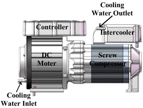
Figure 1.
Appearance diagram of the FCN155 fuel cell compressor.
2.2. Compressor Test Rig
Water is a product of the PEMFC working process and is also necessary for humidifying air. In addition, the conversion efficiency of PEMFCs is about 50%, which means a large amount of heat will be generated during the working process. And the heat dissipation problem can be solved by the water management system conveniently. Therefore, there is a strong correlation between water and PEMFC. Therefore, it is more suitable for the cooling jacket of the dry screw compressor used in PEMFC to adopt water as the working medium than other liquids such as oil and ethylene glycol. Therefore, the test rig only uses water as the cooling liquid.
The schematic diagram of the test rig used to test the cooling effect of the cooling water jacket of the dry twin-screw air compressor are shown in Figure 2. The test rig comprises a power supply system, control system, water cooling system and data acquisition system surrounding the integrated compressor, DC motor, controller, and intercooler mentioned above.
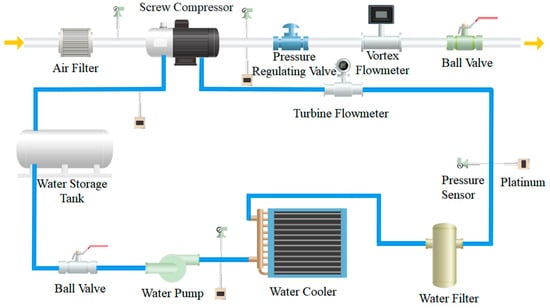
Figure 2.
Schematic diagram of the test rig.
The power supply system is relatively simple, mainly composed of a DC power supply for the screw compressor and a 24 V DC power supply for the data measurement system. The function of the former is to convert the input 380 V three-phase electricity into the output 450~720 V DC electricity, which is then input into the socket located on the controller to drive the DC motor. And the latter is responsible for supplying power to the sensors, flowmeters, and controller of the FCN155 fuel cell compressor.
The control system mainly consists of a computer, CAN analyzer, and controller. The computer utilizes CANTest software (version 2.7) and sends control commands to the controller through the relay of the CAN analyzer to achieve the functions of switching and controlling speed.
The water supply system is relatively complex, consisting of a water storage tank, a water pump, a turbine flowmeter, an air-cooled water cooler, and a water filter. Water is stored in a tank, and circulating power is provided by a water pump. The flow rate of cooling water is regulated by a ball valve in the water circuit and a bypass valve on the water pump and measured by a turbine flowmeter. After entering the water jacket of the compressor, cooling water will take away the heat generated by air compression and enter the water storage tank. Subsequently, cooling water is sent by the water pump to the air-cooled water cooler and is filtered by the water filter before returning to the compressor.
The data measurement system consists of various instruments used to measure data such as temperature, pressure, flow rate, etc. Detailed information about these measurement instruments is listed in Table 2.

Table 2.
Measurement instruments used in the test rig.
Figure 3 shows photos of the test rig. As shown in the photo, (a) is the exhaust pipeline of the compressor, which is mainly composed of a vortex flow meter, valves, and muffler. In traditional compressor experiments, the measurement of volumetric flow rate is usually completed by a nozzle flowmeter. However, the volumetric flow measurement involving fuel cell systems usually uses vortex flow meters, so the test rig in this paper adopted it instead of a nozzle flowmeter. The pressure-regulating valve is used to adjust the discharge pressure, and the ball value can change the air pressure in the vortex flowmeter to increase its measurement upper limit to a certain extent. And a muffler can reduce exhaust noise. Photo (b) shows the main body of the test rig, including the FCN155 fuel cell compressor, the entire water supply system, and the suction and discharge pipeline. Air purified by the filter enters the screw compressor and then enters the test rig shown in photo (a) through the exhaust pipeline. Photo (c) shows the power supply system and part of the control system and data measurement system. They are connected to the test rig in photo (b) through various data cables and wires.

Figure 3.
Photos of the test rig. (a) Exhaust pipeline. (b) Main body. (c) Power supply system and part of other systems.
2.3. Performance Evaluation and Uncertainty Analysis
The equipment mentioned in Table 2 is sufficient to measure parameters such as temperature, pressure, volumetric flow rate, etc. And performance parameters, including volumetric efficiency, adiabatic efficiency, and specific power, need to be calculated through formulas.
The volumetric efficiency , which reflects the degree of perfection in utilizing the geometric dimensions of the compressor, is the ratio of the actual volumetric flow rate to the theoretical volumetric flow rate determined by the rotor geometry:
The isentropic efficiency , which reflects the degree of perfection in the energy utilization of the compressor, is the ratio of the isentropic compression power consumption to the actual shaft power :
where adiabatic power can be calculated by
Specific power , indicating the energy efficiency comprehensively, is the ratio of the actual shaft power to the actual volumetric flow rate :
According to error propagation analysis, and using the standard deviation, the uncertainty of the volumetric efficiency, adiabatic efficiency, and specific power can be calculated by
Taking the measured data at 9000 rpm and with a 10 L/min cooling water flow rate as an example, an error analysis was conducted as below. The relative error of the measured compressor volume flow rate is ±1.73%, and the relative error of the theoretical compressor volume flow rate is ±1%. Then, the relative error for the volumetric efficiency can be calculated as ±2.00%. The relative error of the isentropic compression power consumption is ±2.02%, and the relative error of the actual shaft power is ±1%. Then, the relative error for the isentropic efficiency can be calculated as ±2.25%. And the relative error of the specific power can be calculated as ±2.00%.
3. Results and Discussion
The frequency of the fan of the air-cooled water cooler was fixed at 30 Hz. The rotating speed of the male rotor changed from 6000 rpm to 10,000 rpm. And the discharge pressure in this experiment had two values, 1.5 bar and 2 bar.
The value of the flow rate of cooling water is quite crucial. If the difference in values is too small, this may lead to less significant changes in compressor performance, thereby disturbing the judgment of the results. But if the numerical difference is too large, the smaller water flow rate may cause the compressor to overheat under high-speed and high-discharge pressure conditions, leading to damage. The manufacturer recommends a cooling water flow rate of 8~12 L/min for the compressor. Considering the potential margin of the recommended values and the lower ambient temperature in the experiment (about 15 °C), this study ultimately chose 3 L/min and 10 L/min as the cooling water flow rates for the experiment.
3.1. Outer Surface Temperature
Figure 4 shows the visible light photo of the compressor during thermal imaging and Figure 5 shows partial infrared photos at 1.5 bar from the same perspective as Figure 4. The temperature span of the color palette for all infrared photos was uniformly set to 14~70 °C in order to visually present the temperature level through color. In addition, temperature displays for ten points from a to j were added, and their temperature values are listed on the right side of the infrared photo.
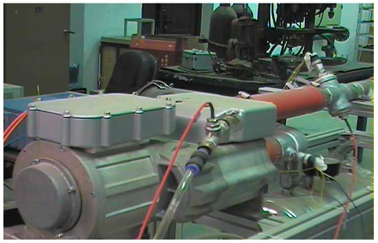
Figure 4.
Visible light photo of the compressor.
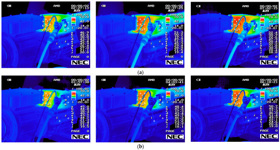
Figure 5.
Infrared photos of the compressor at 1.5 bar. (a) Cooling water flow rate of 3 L/min and rotating speeds of 6000 rpm, 8000 rpm, and 10,000 rpm, respectively. (b) Cooling water flow rate of 10 L/min and rotating speeds of 6000 rpm, 8000 rpm, and 10,000 rpm, respectively.
It can be seen that the temperature distribution at the motor and compressor was relatively uniform and the average temperature was low. However, the outer surface temperature of the intercooler and the exhaust pipe connected to it was significantly higher than elsewhere. Due to the fact that the surface temperature at the intercooler was closest to the compressor discharge temperature, its variation best reflected the impact of rotating speed and cooling water flow rate on compressor performance, which was also the reason for setting the greatest number of points at this location.
Comparing the color and temperature value of the intercooler in the photos, it can be observed that the outer surface temperature increased with the increase in the rotating speed. This is because a higher rotating speed causes the compressor to generate more heat per unit time. Meanwhile, the outer surface temperature decreased with the increase in the cooling water flow rate, which indicated that the increase in the cooling water flow rate had, to some extent, reduced the discharge temperature.
3.2. Volumetric Flow Rate and Volumetric Efficiency
Figure 6 shows the effect of the rotating speed, discharge pressure, and cooling water flow rate on the volumetric flow rate. It can be seen that the volumetric flow rate showed a certain degree of increase as the cooling water flow rate increased. In fact, the increase in the volumetric flow rate was about 0.5%. The eight-shaped inner wall of the working chamber of the compressor will undergo irregular deformation at high temperatures, and its left and right sides will expand outward while the upper and lower sharp points will expand inward. The increase in the cooling water flow rate will effectively slow down the deformation of the inner wall of the working chamber and reduce the average gap between it and screw rotors, thereby reducing air leakage backflow and increasing the discharge flow rate. In addition, an increase in the flow rate of cooling water can also result in the sharp points of the inner wall being far away from the screw rotors, which will effectively improve the extreme working conditions of the dry screw compressor. Moreover, it can also be seen that the volumetric flow rate showed an almost linear increase with the increase in the rotating speed and a decrease with the increase in the discharge pressure. This is because the higher rotating speed results in more air being discharged per unit time and the higher discharge pressure increases exhaust leakage.
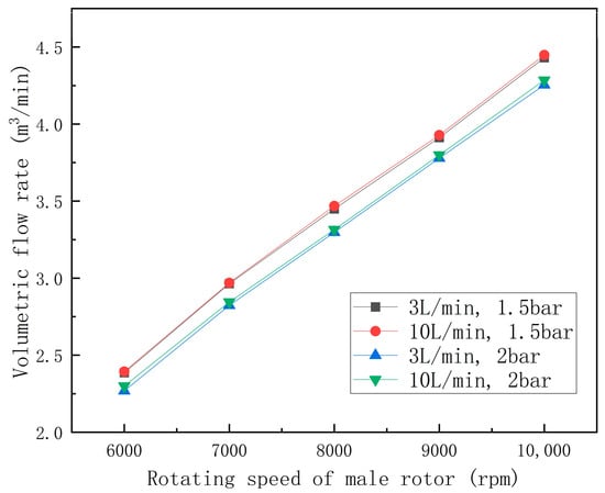
Figure 6.
Effect of the rotating speed, discharge pressure, and cooling water flow rate on the volumetric flow rate.
Figure 7 shows the variation in volumetric efficiency with the rotating speed, discharge pressure, and cooling water flow rate. The volumetric efficiency showed the same but more pronounced pattern, as shown in Figure 6, with the change in the cooling water flow rate, indicating that the increase in the cooling water flow rate effectively improves volumetric efficiency. And when the discharge pressure was high, its improvement effect was more significant. The reason is also due to the influence of the variation in the average gap between the screw rotor and the working chamber wall on the leakage rate.
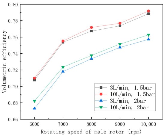
Figure 7.
Effect of the rotating speed, discharge pressure, and cooling water flow rate on the volumetric efficiency.
In addition, volumetric efficiency showed an increase with increasing rotating speed and a decrease with increasing discharge pressure. The leakage rates are nearly constant at different rotating speeds, so the shorter leakage time caused by increased rotating speed will reduce the net leakage mass. And the increase in the discharge pressure will increase gas leakage.
3.3. Power Consumption and Adiabatic Efficiency
Figure 8 shows the effect of rotating speed, discharge pressure, and cooling water flow rate on power consumption. The two curves at the same discharge pressure were very close, indicating that the impact of the cooling water flow rate on power consumption was not significant.
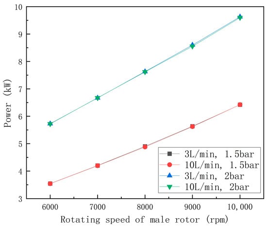
Figure 8.
Effect of the rotating speed, discharge pressure, and cooling water flow rate on power consumption.
Power consumption showed an approximately linear increase with the increase in rotating speed, just like the volumetric flow rate. According to Formula (3), the adiabatic power is proportional to the volumetric flow rate, so the increase in the volumetric flow rate caused by the increase in rotating speed will lead to an increase in power consumption. At a certain cooling water flow rate and given rotating speed, power consumption increased with the increasing in discharge pressure.
Figure 9 shows the effect of the rotating speed, discharge pressure, and cooling water flow rate on adiabatic efficiency. It can be noted that the adiabatic efficiency under various operating conditions was generally low, ranging from 0.50 to 0.58. This is because the dry twin-screw compressor has a large gap but does not receive a liquid seal, which leads to significant leakage and reduces adiabatic efficiency. The dry twin-screw compressor studied in Reference [10] also exhibits similar adiabatic efficiency.
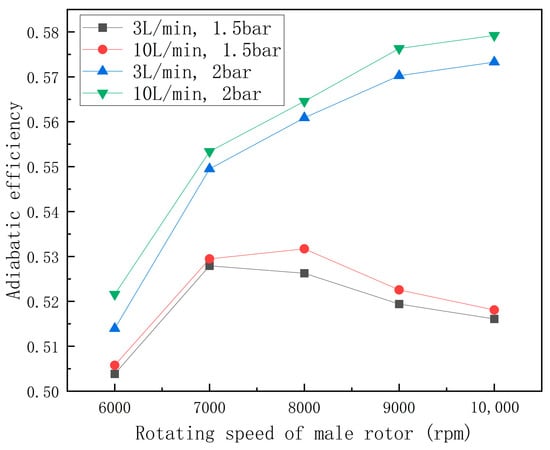
Figure 9.
Effect of the rotating speed, discharge pressure, and cooling water flow rate on adiabatic efficiency.
At a given rotating speed and discharge pressure, adiabatic efficiency showed a significant improvement with the increase in the cooling water flow rate. This is because a higher cooling water flow rate makes the compressor work closer to isothermal compression, and the shaft power is closer to the adiabatic compression power.
The adiabatic efficiency showed different trends with increasing rotating speed at different discharge pressures. When the discharge pressure was 2 bar, the adiabatic efficiency continued to increase with the increase in the rotating speed. When the discharge pressure was 1.5 bar, the maximum adiabatic efficiency occurred around 7000 rpm and 8000 rpm, and the adiabatic efficiency increased first and then decreased with the increase in the rotating speed. On the one hand, the increase in rotating speed will cause larger flow losses and larger friction losses, resulting in a decrease in adiabatic efficiency. On the other hand, the increase in rotating speed brings greater volumetric efficiency, resulting in an increase in adiabatic efficiency. The different growth rates of the former and the latter with increasing rotating speed led to different trends in adiabatic efficiency. Moreover, the adiabatic efficiency increased with the increase in the discharge pressure.
3.4. Discharge Temperature and Specific Power
Figure 10 shows the variation in discharge temperature with the rotating speed, discharge pressure, and cooling water flow rate. Comparing the discharge temperature in Figure 10 with the highest surface temperature of the intercooler in Figure 5, it can be seen that cooling water had a significant cooling effect on discharge gas.
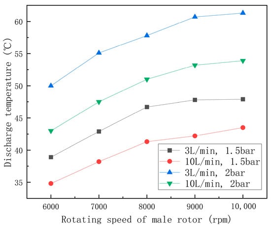
Figure 10.
Effect of the rotating speed, discharge pressure, and cooling water flow rate on the discharge temperature.
At a given rotating speed and discharge pressure, the discharge temperature significantly decreased with the increase in the cooling water flow rate. In addition, it can be seen that the discharge temperature increased with the increase in the rotating speed and the increase in the discharge pressure.
Figure 11 shows the effect of rotating speed, discharge pressure, and cooling water flow rate on specific power. The increase in the cooling water flow rate led to a decrease in specific power, which meant that the energy consumption of the compressor relatively decreased.
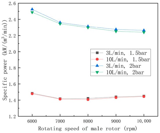
Figure 11.
Effect of the rotating speed, discharge pressure, and cooling water flow rate on specific power.
At 2 bar, the specific power decreased more and more slowly with the increase in the rotating speed, while at 1.5 bar, the specific power decreased first and then increased with the increase in the rotating speed. This was caused by the different rates at which the volumetric flow rate and shaft power increased with increasing rotating speed. Moreover, it can be seen that the specific power increased with the increase in the discharge pressure.
4. Conclusions
In order to study the effect of a cooling jacket on the performance of a dry twin-screw compressor, a test rig was built and an investigation on a dry twin-screw compressor for fuel cell vehicles was carried out. Except for shaft power, the surface temperature, volumetric flow rate, volumetric efficiency, adiabatic efficiency, discharge temperature, and specific power in the compressor all showed improvement with the increase in the cooling water flow rate. Therefore, it can be considered that the existence of a cooling jacket is of great significance for improving the performance of dry screw compressors and improving extreme operating conditions.
Author Contributions
Conceptualization, C.W.; methodology, C.W.; formal analysis, M.L. and Y.L. (Yanpeng Li); investigation, M.L., Y.L. (Yanpeng Li), Y.L. (Yuchen Li) and L.L.; resources, M.L., Y.L. (Yanpeng Li), Y.L. (Yuchen Li) and L.L.; data curation, M.L. and Y.L. (Yanpeng Li); writing—original draft preparation, M.L.; writing—review and editing, C.W.; visualization, M.L. and Y.L. (Yanpeng Li); supervision, Z.X.; project administration, Z.X.; funding acquisition, C.W. All authors have read and agreed to the published version of the manuscript.
Funding
This research was funded by Research on the Active Control Mechanism of Penetrating Water Injected Axially for a Variable-lead Screw Compressor and Expander used in a Proton Exchange Membrane Fuel Cell System and the High-efficiency Integration Mechanism of a Coupling Water System, grant number 52206021, National Natural Science Foundation of China.
Data Availability Statement
The data presented in this study are available on request from the corresponding author. The data are not publicly available due to privacy.
Conflicts of Interest
The authors declare no conflicts of interest.
References
- Tanç, B.; Arat, H.T.; Conker, Ç.; Baltacioğlu, E.; Aydin, K. Energy distribution analyses of an additional traction battery on hydrogen fuel cell hybrid electric vehicle. Int. J. Hydrog. Energy 2020, 45, 26344–26356. [Google Scholar] [CrossRef]
- Sharaf, O.Z.; Orhan, M.F. An overview of fuel cell technology: Fundamentals and applications. Renew. Sustain. Energy Rev. 2014, 32, 810–853. [Google Scholar] [CrossRef]
- Mao, L.; Jackson, L.; Jackson, T. Investigation of polymer electrolyte membrane fuel cell internal behaviour during long term operation and its use in prognostics. J. Power Sources 2017, 362, 39–49. [Google Scholar] [CrossRef]
- Dubeński, K.; Czarnigowski, J.; Durakiewicz, P.; Szewc, S. The test-bed research of a low power low-temperature PEM fuel cell. J. Phys. Conf. Ser. 2021, 1736, 012057. [Google Scholar] [CrossRef]
- Liu, Q.; Lan, F.; Chen, J.; Zeng, C.; Wang, J. A review of proton exchange membrane fuel cell water management: Membrane electrode assembly. J. Power Sources 2022, 517, 230723. [Google Scholar] [CrossRef]
- Kerviel, A.; Pesyridis, A.; Mohammed, A.; Chalet, D. An Evaluation of Turbocharging and Supercharging Options for High-Efficiency Fuel Cell Electric Vehicles. Appl. Sci. 2018, 8, 2474. [Google Scholar] [CrossRef]
- Tirnovan, R.; Giurgea, S. Efficiency improvement of a PEMFC power source by optimization of the air management. Int. J. Hydrog. Energy 2012, 37, 7745–7756. [Google Scholar] [CrossRef]
- DOE. DOE Hydrogen and Fuel Cells Program Record: Fuel Cell System Cost 2015; United States Department of Energy: Washington, DC, USA, 2015. [Google Scholar]
- Chen, H.; Liu, Z.; Ye, X.; Yi, L.; Xu, S.; Zhang, T. Air flow and pressure optimization for air supply in proton exchange membrane fuel cell system. Energy 2022, 238, 121949. [Google Scholar] [CrossRef]
- He, Y.; Xing, L.; Zhang, Y.; Zhang, J.; Cao, F.; Xing, Z. Development and experimental investigation of an oil-free twin-screw air compressor for fuel cell systems. Appl. Therm. Eng. 2018, 145, 755–762. [Google Scholar] [CrossRef]
- Seshaiah, N.; Sahoo, R.K.; Sarangi, S.K. Theoretical and experimental studies on oil injected twin-screw air compressor when compressing different light and heavy gases. Appl. Therm. Eng. 2010, 30, 327–339. [Google Scholar] [CrossRef]
- Zhao, B.; Song, H.; Gao, D.; Xu, L. Flow and heat transfer coupling analysis of oil-gas two-phase fluid in clearance of single screw compressor based on fuzzy curvelet finite element method. Case Stud. Therm. Eng. 2020, 22, 100788. [Google Scholar] [CrossRef]
- Seshaiah, N.; Ghosh, S.K.; Sahoo, R.K.; Sarangi, S.K. Mathematical modeling of the working cycle of oil injected rotary twin screw compressor. Appl. Therm. Eng. 2007, 27, 145–155. [Google Scholar] [CrossRef]
- Hsieh, S.H.; Shih, Y.C.; Hsieh, W.-H.; Lin, F.Y.; Tsai, M.J. Calculation of temperature distributions in the rotors of oil-injected screw compressors. Int. J. Therm. Sci. 2011, 50, 1271–1284. [Google Scholar] [CrossRef]
- Krichel, S.V.; Sawodny, O. Dynamic modeling of compressors illustrated by an oil-flooded twin helical screw compressor. Mechatronics 2011, 21, 77–84. [Google Scholar] [CrossRef]
- Wang, C.; Xing, Z.; Hou, F.; Wu, H.; Yu, Z. Research on axis orbit of the journal bearing lubricated with oil and refrigerant mixtures in a twin-screw refrigeration compressor. Int. J. Refrig. 2018, 90, 1–11. [Google Scholar] [CrossRef]
- Dhayanandh, K.K.; Rameshkumar, K.; Sumesh, A.; Lakshmanan, N. Influence of oil injection parameters on the performance of diesel powered screw air compressor for water well application. Measurement 2020, 152, 107323. [Google Scholar] [CrossRef]
- Basha, N.; Kovacevic, A.; Rane, S. Numerical investigation of oil injection in screw compressors. Appl. Therm. Eng. 2021, 193, 116959. [Google Scholar] [CrossRef]
- Yang, S.; Ouyang, H.; Wu, Y.; Wang, L.; Mei, L.; Wang, H. CFD simulation for the internal pressure characteristics of an oil-injected twin-screw refrigeration compressor. Int. J. Refrig. 2021, 126, 143–154. [Google Scholar] [CrossRef]
- Wu, W.; Zhang, Z.; Wang, X.; Yang, L.; Feng, Q. A Bench Evaluation Test for Refrigeration Oils in a Refrigeration System Using a Screw Compressor. Appl. Sci. 2019, 9, 3202. [Google Scholar] [CrossRef]
- Tian, Y.; Shen, J.; Wang, C.; Xing, Z.; Wang, X. Modeling and performance study of a water-injected twin-screw water vapor compressor. Int. J. Refrig. 2017, 83, 75–87. [Google Scholar] [CrossRef]
- Shen, J.; Xing, Z.; Zhang, K.; He, Z.; Wang, X. Development of a water-injected twin-screw compressor for mechanical vapor compression desalination systems. Appl. Therm. Eng. 2016, 95, 125–135. [Google Scholar] [CrossRef]
- Wang, C.; Xing, Z.; Chen, W.; Yang, Q.; He, Z. Development of an oil free water-lubricated twin-screw air compressor. Appl. Therm. Eng. 2018, 143, 396–402. [Google Scholar] [CrossRef]
- Li, J.; Wu, H.; Wang, B.; Xing, Z.; Shu, P. Research on the performance of water-injection twin screw compressor. Appl. Therm. Eng. 2009, 29, 3401–3408. [Google Scholar] [CrossRef]
- Ous, T.; Mujic, E.; Stosic, N. Experimental investigation on water-injected twin-screw compressor for fuel cell humidification. Proc. Inst. Mech. Eng. Part C J. Mech. Eng. Sci. 2012, 226, 2925–2932. [Google Scholar] [CrossRef]
- Xie, J.; Peng, C.; Zhang, W.; Zhao, C.; Feng, Q. Experimental and Simulated Investigation of Lubrication Characteristics of a Water-Lubricated Bearing in a Single-Screw Compressor. Appl. Sci. 2021, 11, 9920. [Google Scholar] [CrossRef]
Disclaimer/Publisher’s Note: The statements, opinions and data contained in all publications are solely those of the individual author(s) and contributor(s) and not of MDPI and/or the editor(s). MDPI and/or the editor(s) disclaim responsibility for any injury to people or property resulting from any ideas, methods, instructions or products referred to in the content. |
© 2024 by the authors. Licensee MDPI, Basel, Switzerland. This article is an open access article distributed under the terms and conditions of the Creative Commons Attribution (CC BY) license (https://creativecommons.org/licenses/by/4.0/).