Article

Experimental and Numerical Analysis of the Solar Collector with Stainless Steel Scourers Added to the Absorber Surface

1
Department of Mechanical Engineering, Dicle University, Diyarbakir 21280, Turkey
2
Department of Mechanical Engineering, Firat University, Elazig 23119, Turkey
3
Technology Faculty, Firat University, Elazig 23279, Turkey
*
Author to whom correspondence should be addressed.
Appl. Sci. 2024, 14(6), 2629; https://doi.org/10.3390/app14062629
Submission received: 13 February 2024 / Revised: 15 March 2024 / Accepted: 19 March 2024 / Published: 21 March 2024
(This article belongs to the Section Energy Science and Technology)

Abstract

:
In this study, a numerical and experimental analysis of a solar collector with roughness elements in the form of stainless-steel scourers on the absorber surface is presented. According to the location type and number of the stainless steel scourers, the absorber surfaces are referred to as the complex surface (C1), less complex surface (C2), and flat surface (C3). A Computational Fluid Dynamics (CFD) analysis was carried out using ANSYS-CFX-R18.2 commercial software. The results were verified with the experimental study. After the numerical study was confirmation with the experimental study, then the detailed investigation was performed by numerical simulations. The extracted results of the numerical and experimental analysis concerned the air temperature and velocity, and thermal efficiency, which varied with respect to the type of collector. As a result, the C1 type yielded the highest air velocity and air temperature, while the lowest values of air velocity and temperature were recorded for the C3 type, according to both the numerical analysis and experimental tests. This trend was similar for the efficiencies. The efficiency was nearly 80% for collectors with stainless-steel scourers, whilst it was 55% for the flat plate collector. The results showed that the experimental and numerical results agreed well.

1. Introduction

When compared to other energy sources, solar energy has drawn a lot of attention as a reliable and efficient way to address the growing global energy demand [1]. Photovoltaic panels can be used to convert solar energy directly into electricity or heat at different temperatures. In addition, it is a clean, free energy source that contributes to reducing global warming. But in order to transform solar radiation into usable energy, certain highly efficient equipment is required.
There are various arrangements for solar air collectors. Their inexpensive cost, straightforward structure, and design define them. However, because of their low heat transfer coefficient, air solar collectors have low thermal efficiency. Numerous studies have bee n carried out to improve this crucial component in order to improve the thermal performance of air solar collectors. The absorber plate of the air solar collector has undergone a number of changes in an effort to improve heat transfer [2].
A good method of raising the radiative heat transfer is to add artificial roughness, namely surface-enhancing elements that break the laminar sub-layer and cause turbulence to occur over the absorber plate. Nonetheless, there are several drawbacks to manufactured roughness that are associated with friction losses. Therefore, research on various forms of artificial roughness is required, along with optimization of the crucial elements of pressure loss and heat transfer. Fins that are inclined, triangular, circular, elliptical, or rectangular in shape are among the several geometric shapes and artificial roughness forms that have been suggested and studied [1,2].
Kishk et al. [2] presented a novel concept that addresses environmental concerns by utilizing recyclable aluminum cans as the absorber plate for an air solar collector. The results showed that by adding the cans to the absorber surface, the thermal efficiency increased from 25% to 63%. Yadav et al. [3] numerically investigated the effect of adding circular and semi-circular ribs to the surface of a solar air heater. The results showed that the semi-circular rib gives the highest performance. Njomo [4] studied unsteady-state heat exchange mechanisms that governed the functioning of a bare single-pass solar collector, using non-porous selective absorbers. The derived mathematical model was subsequently utilized to forecast the thermal efficiency of this kind of collector. The installation of surface-enhancing elements in the form of ribs on the absorber plate under turbulent flow conditions was investigated numerically by Chaube et al. [5]. It was shown that the heat transfer was much improved as compared to a smooth surface. Pashchenko et al. [6] investigated how technological and design factors affected the thermal and aerodynamic processes occurring in a solar air heater with light-absorbing L-shaped fins. They discovered that the solar air heater with fins, had high thermo-aerodynamic characteristics. Karim and Hawlader [7] conducted both theoretical and experimental analysis using finned and V-corrugated air heaters to enhance the effectiveness of traditional air heaters. Ammar et al. [8] created a 3D steady-state CFD model of a flat-plate solar air collector with a selective absorber under steady-state conditions. They discovered an 81% enhancement in thermal efficiency. Badiei et al. [9] developed a 3D CFD transient model of a solar collector with fins that were incorporated into the phase change materials. The thermal efficiency increased from 33% to 46% when using the fins with phase change materials. Panchal et al. [10] presented a report related to a performance evaluation of using a tube solar collector with perforated fins. They showed that surface-enhancing fins increased the efficiency and hence decreased the cost of energy. Saxena et al. [11] presented an experimental study including the modification of a solar cooker. It was determined that the modification provided 53 percent efficiency compared to the traditional type solar cooker. It was determined that the modification provided 53.81% efficiency compared to the conventional solar cooker.
Overall, the use of surface enhancing elements on the absorber surface of solar collectors plays a crucial role in maximizing their efficiency and effectiveness in harnessing solar energy for heating purposes. Therefore, in this study, we sought to improve the efficiency of solar collectors by adding stainless steel scourers on the absorber surface. Since the cost of stainless-steel scourers is low, it is very easy to find them around the world, and their porous structure is unique. The usability of them in the context of solar collectors as surface enhancing elements was investigated in the present study. For this purpose, the effects of stainless-steel scourers placed on the absorber surface on air velocity, temperature, and collector efficiency have been investigated numerically and experimentally.

2. Materials and Methods

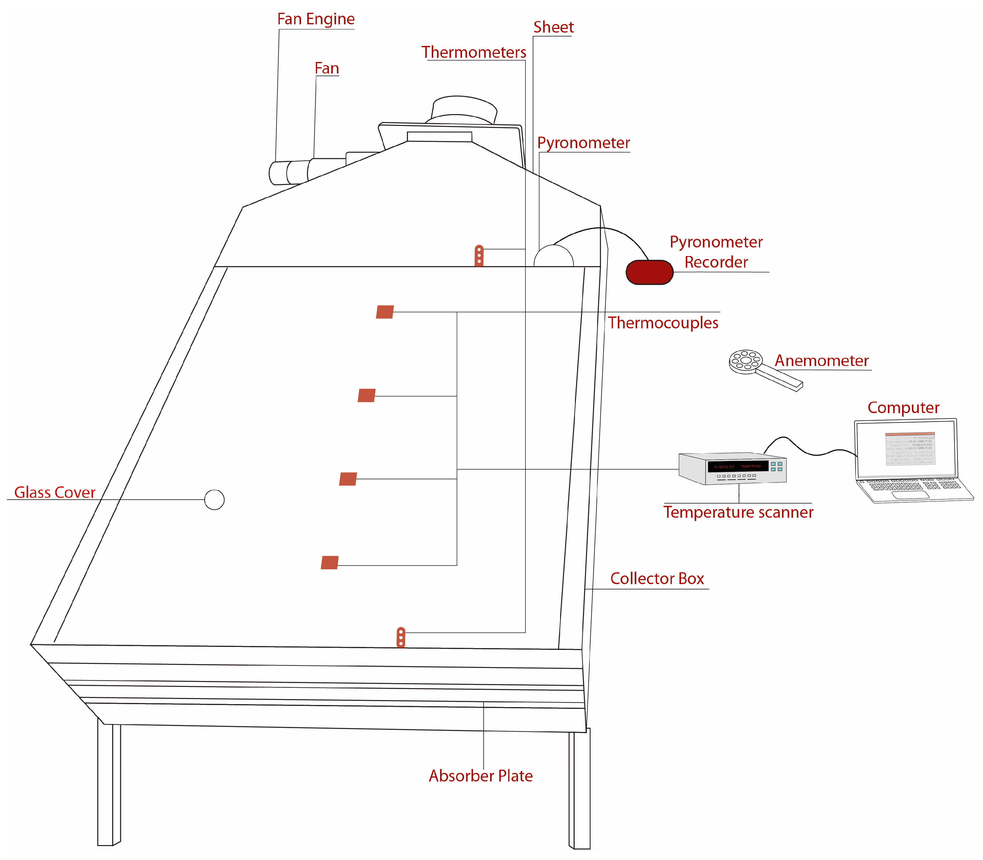
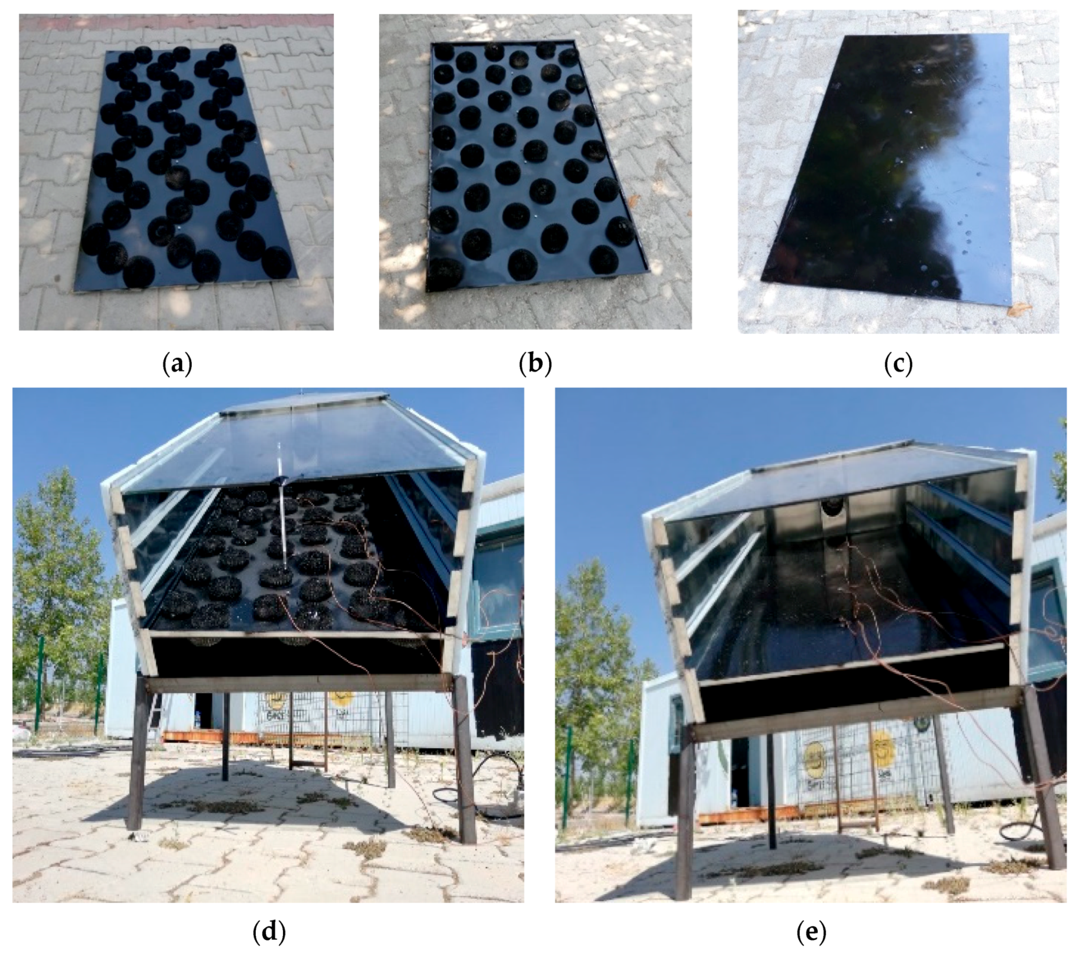
2.1. Experimental Study

The experimental setup was previously used by a co-author of present study [12,13]. The general setup included a solar air heater, namely a solar collector that was 120 cm in length, 80 cm in width, and 40 cm in height. It should be noted that, in order to make the values realistic, the dimensions of a frequently sold collector produced by a collector company were taken as basis. Its transparent cover, casing material, and insulation material consisted of 4 mm-thick window glass, 3 cm-thick Styrofoam, and chipboard wood, correspondingly. The collector faced south and was tilted at a 38° horizontal inclination. Figure 1 depicts a picture of the experimental arrangement.
As mentioned above, this study aimed to analyze a solar collector system with stainless-steel scourers on the absorber surface. Stainless-steel scourers are mostly used in homes for cleaning and scrubbing tasks. Three “handfuls” in a packet cost only around USD 1, indicating that the inclusion of scourers has no financial impact on the overall collector system cost. This substance is structured like metal “swarf”, which is metal cuttings from metal turning operations. It has a very regular rectangular cross section, typically 400–500 μm by 20–30 μm, and is fashioned into “disks” that fit in the palm of a human hand. Since this is a “random structure” material, one must carefully press the material to the proper bulk density (or porosity) while accounting for the “rectangular wire’s” actual average cross section in order to manage the hydraulic radius [14,15].
The most important part of the solar air collector is the absorber surface. Three different absorbing surfaces were used in the experimental study. The construction of absorber surfaces guarantees the availability of airflow on both sides of the surface to increase efficiency. The absorber surfaces were created using 180 porous steel wool, which was attached to the top and bottom of a 1.5 mm-thick galvanized sheet with a type of silicone glue. This sheet was coated with black matte paint to form a surface that absorbs radiation, consistent with the bonding procedure. The first of the absorber surfaces contained 102 scourers in a complex arrangement (C1), as displayed in Figure 2a, and the second contained 78 scourers in a regular row (C2), as presented in Figure 2b. No scourer was used on the third absorber surface (C3), as shown in Figure 2c.
The experiments were carried out in the city of Elazig, located in the Middle East region of Turkey, in a one-month period between the 1st and 30th of July in 2020. The measurements were conducted with two air flow rates (0.05 and 0.025 kg/s) and three distinct absorber surface geometries (C1, C2, and C3). The inlet and outlet air temperature and 4-point surface temperatures were the obtained parameters that were thought to affect efficiency. Hence, a comprehensive numerical analysis was performed to obtain more information. The following section introduces the numerical analysis.

2.2. Data Reduction

In general, the efficiency of a solar air heater is described by the ratio of usable collected energy in the collector to the solar energy that normally reaches the collector surface [12].
η = Q I   A c
where Q is the usable collected energy, I is the radiation, and the Ac is the surface area of the collector (Ac = 0.8 × 1.2 = 0.96 m2). The usable collected energy is defined as follows:
Q = m ˙ C p Δ T  
where ΔT refers the difference between the inlet and outlet temperature of air.

2.3. Uncertainty Analysis

Uncertainty analysis is important in experimental studies, especially in detecting errors and uncertainties caused by measurement devices. The Kline and McClintock [16] methodology is used to estimate the uncertainties of the measured values. According to this method, in a measurement with n independent variables, R is the dimension to be measured; x1, x2, x3, , xn are the variables affecting the measurement; and w1, w2, w3, …, wn are the uncertainties related to the independent variables.
W R = R x 1 w 1 2 + R x 2 w 2 2 + R x 3 w 3 2 + + R x n w n 2
The independent parameters measured in the experiments were the inlet and outlet temperature of air, ambient temperature, air velocity, and solar radiation. To perform the experiments, T-type thermocouples with ±0.018 °C accuracy, a vane-type anemometer (AM-4206M, air velocity + air flow) with ±2% accuracy, and a Kipp and Zonen CM 11 Pyranometer with 1% accuracy were used. The total uncertainties in estimating the dependent parameters was 4.5% for the mass flow rate of air and 1.8% for the efficiency.

3. Numerical Analysis

Numerical analysis provides a powerful tool for understanding the performance of solar air heaters and optimizing their design for increased efficiency. Therefore, a numerical analysis of a solar air collector was carried out to simulate the performance of the system. The goal was to predict the temperature and velocity distribution of the passing air and the wall temperature on the absorber surface with stainless-steel scourers.
All of the simulations in this study were run using the commercial CFD code software ANSYS-CFX-R18.2. The geometric modeling of the experimental setup served as the first step in the solution process. The collector in the experimental setup was modeled one-to-one in 3D. Mesh independence was also carried out in order to attain the proper level of precision and to utilize the available computer resources as efficiently as possible. The equations of continuity, momentum (Navier–Stokes) and energy were solved for fully developed, turbulent, steady-state, incompressible flow. As the discretization method, the finite element method with pressure velocity coupling was used to tackle the current issue. Every plan was second-order upwind.

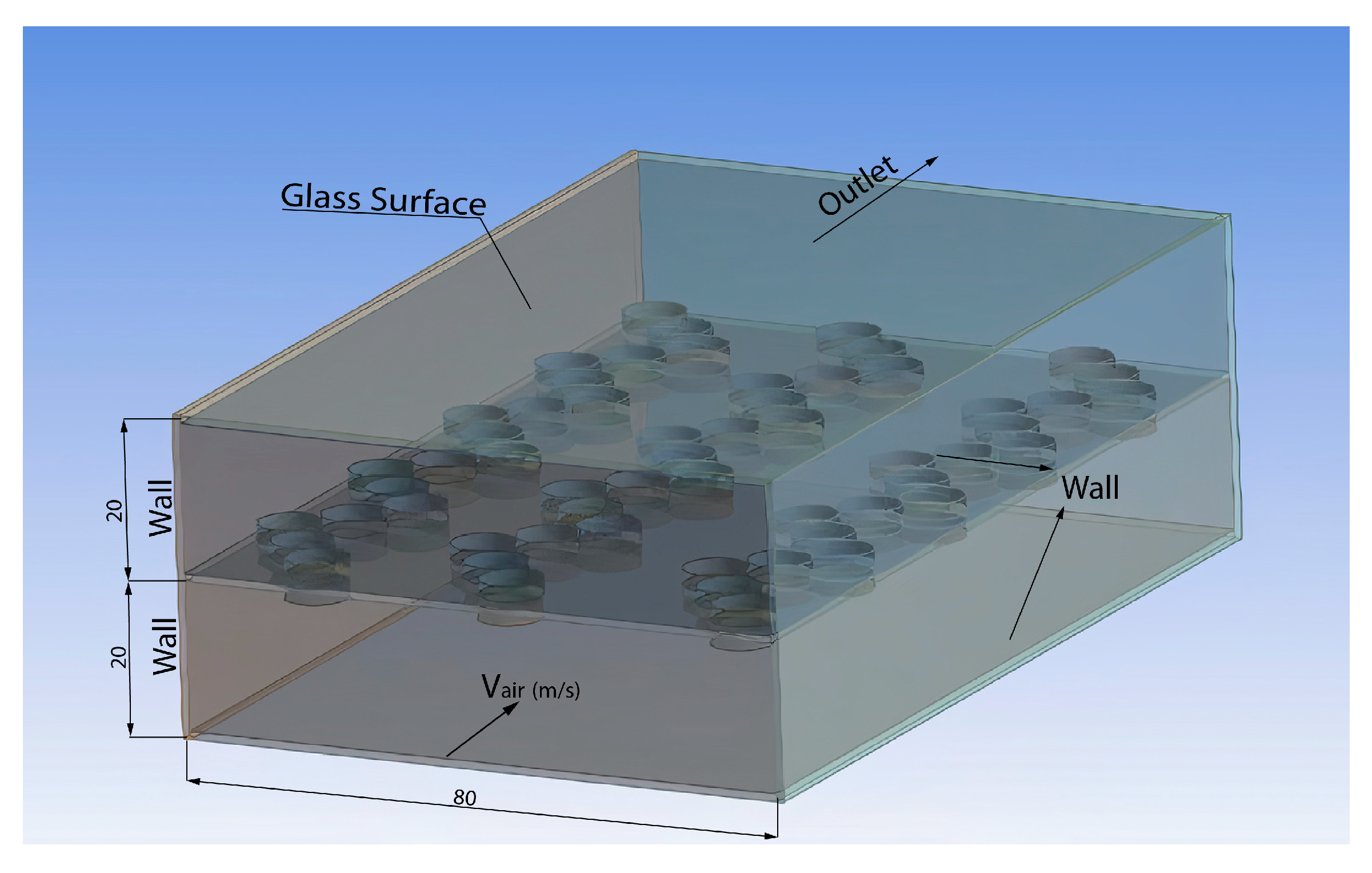
3.1. Physical Problem

As mentioned earlier, the experimental study examined three distinct types of a solar collector absorber surface. The surface-enhancing elements created with the help of stainless-steel scourers in the experimental study were drawn as porous obligations in the numerical study. The solution domain included the collector surface with surface-enhancing elements.

3.2. Governing Equations

The study employed the κ-ε turbulence model to address turbulence in a simplified manner. The κ-ε model is extensively used in the literature for modelling fluid flow in various channels. The variable ‘κ’ signifies the variance of velocity fluctuations, which is commonly known as turbulence kinetic energy, whilst the term ‘ε’ denotes the rate of velocity fluctuation dissipation, which is known as turbulence eddy dissipation. Technical term abbreviations are clarified upon their initial usage. The equations in the κ-ε model include two additional variables [17]:
Continuity equation:
ρ t + x j ρ U j = 0
Momentum equation:
ρ U i t + x j ρ U i U j = p x i + x j μ e f f U i x j + U j x i + S M
where p’ is the modified pressure, SM is the sum of body forces, and µeff is the effective viscosity that accounts for turbulence [17]. Similar to the zero-equation model, the κ-ε model is predicated on the idea of eddy viscosity, meaning that:
μ e f f = μ + μ t
where µt denotes the turbulence viscosity, and the κ-ε model postulates that it is associated with the turbulence kinetic energy and dissipation through the relation.
μ t = C μ ρ + κ 2 ε
The value of the κ-ε turbulence model constant Cµ is 0.09. The differential transport equations for turbulence kinetic energy and turbulence dissipation rate yield the values of κ and ε:
ρ κ t + x j ρ U j κ = x j μ + μ t σ κ κ x j + P κ ρ ε + P κ b
ρ ε t + x j ρ U j ε = x j μ + μ t σ ε ε x j + ε κ C ε 1 P κ C ε 2 ρ ε + C ε 3 P ε b
For incompressible flow, U k / x k is small, and the second term on the right-hand side of the equation is negligible in terms of its contribution to the production. For compressible flow, U k / x k is only large in regions with high velocity divergence, such as at shocks.

3.3. Boundary Conditions
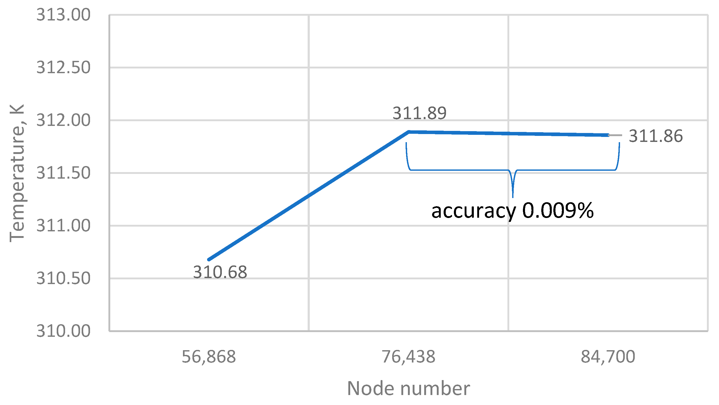
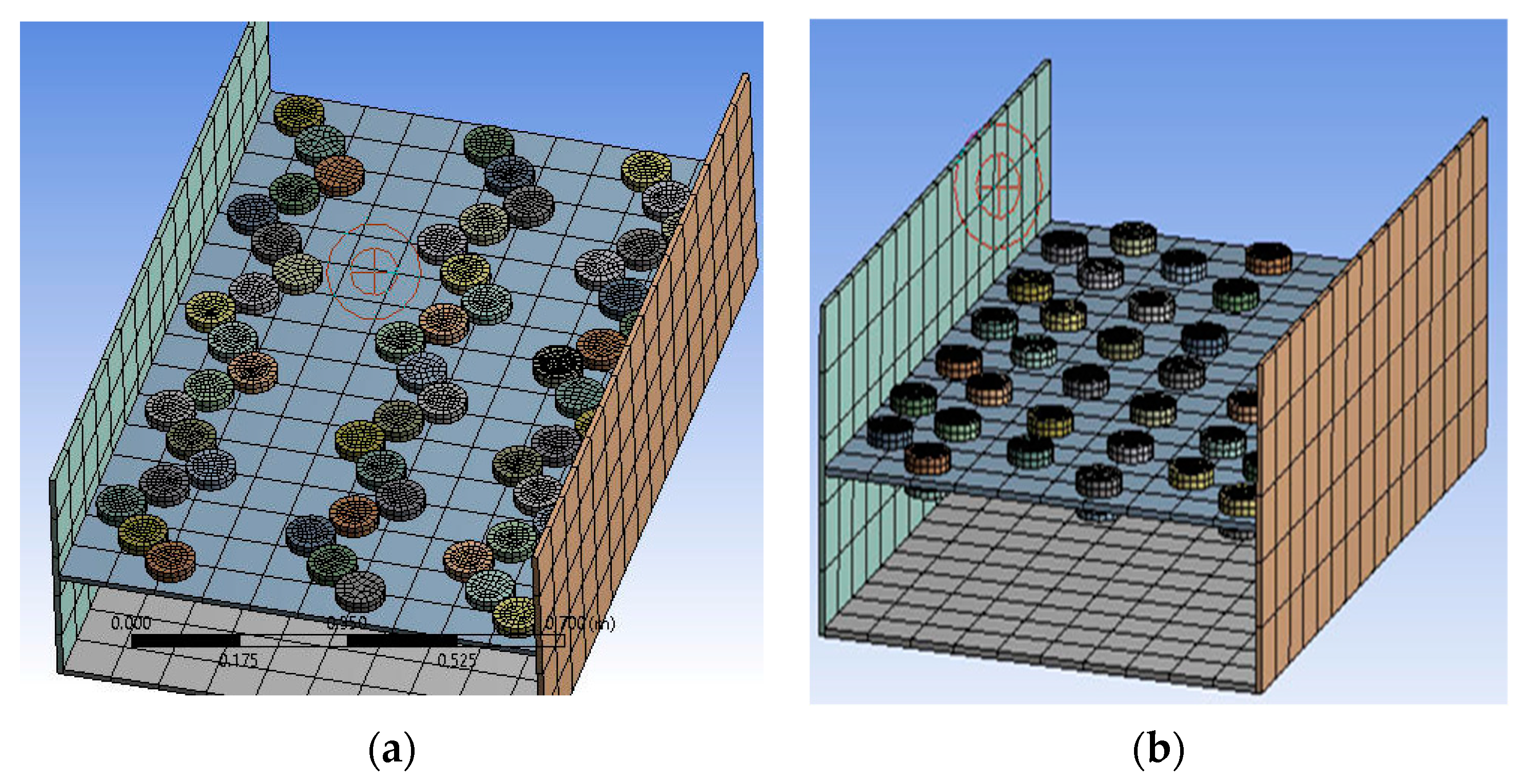
Based on the real sizes of the collectors that were tested in the experiments, the numerical simulation was created. Figure 3 depicts the intended model for absorber surface C1. The collector entry is shown as the inlet and the exit is shown as the outlet. The surface-area-increasing elements on the absorber surface are evaluated as walls. The inlet air temperature is considered to be 36 °C, and the flow rate is 0.05 kg/s. Those two values were obtained from the experimental work. The upper surface, with a constant heat flux of 800 W/m2, is thought to be made of glass. Table 1 lists the characteristics of the glass and air.
In order to achieve high efficiency, the scourers were placed above and below the absorbing surfaces of the collectors. In this case, double air flow was provided.

3.4. Mesh Structure

The mesh accuracy was achieved by resolving the problem utilizing the three distinct grid densities outlined in Figure 4. Great care was taken to create a mesh which enables the attainment of solutions of high accuracy. To this end, a mesh independence study was performed. Meshes consisting of 56,868, 76,438, and 84,700 nodes were employed. From the corresponding solutions, the outlet temperatures were extracted, and the values for the three meshes were used to extrapolate to the case of an infinite number of nodes. From this procedure, it was estimated that the results for the mesh with 76,438 nodes were accurate to 0.009%. Accuracy was ensured by requiring that all residuals (RMS) reduced to 10−6 at the end of the computer run. The maximum iteration number was determined to be 1000 and turbulence numeric option was considered to be first order. The meshed domain for the C1 surfaces with 56,868 node numbers and C2 case with 76,438 node numbers are given in Figure 5a and 5b, respectively.

4. Results and Discussions

The efficacy of solar air collectors is influenced by various factors such as solar radiation value, material, shape, and the dimensions of the collector, etc. One suitable solution for reducing airflow and maximizing heat absorption from the surface of the absorber is to utilize porous materials or obstacles. This approach is highly effective in achieving the desired result. Elements with various geometric shapes and porosity properties can be used as surface enhancing elements. Turbulent flow within the collector may increase, resulting in higher efficiency with minimal losses. From this point of view, to achieve a high efficiency, the collector with complex absorber surface (C1) and the collector with less complex absorber surface (C2) were designed. As the surface-enhancing elements, the stainless-steel scourers were placed above and below the absorber surface. Creating such a double-pass airflow instead of a single-pass airflow increases the heat transfer area and turbulent flow, which further improves the collector efficiency. Unfortunately, obtaining detailed results through experimental work requires high-tech measuring devices and long-term measurements. At this point, numerical study is of great importance.

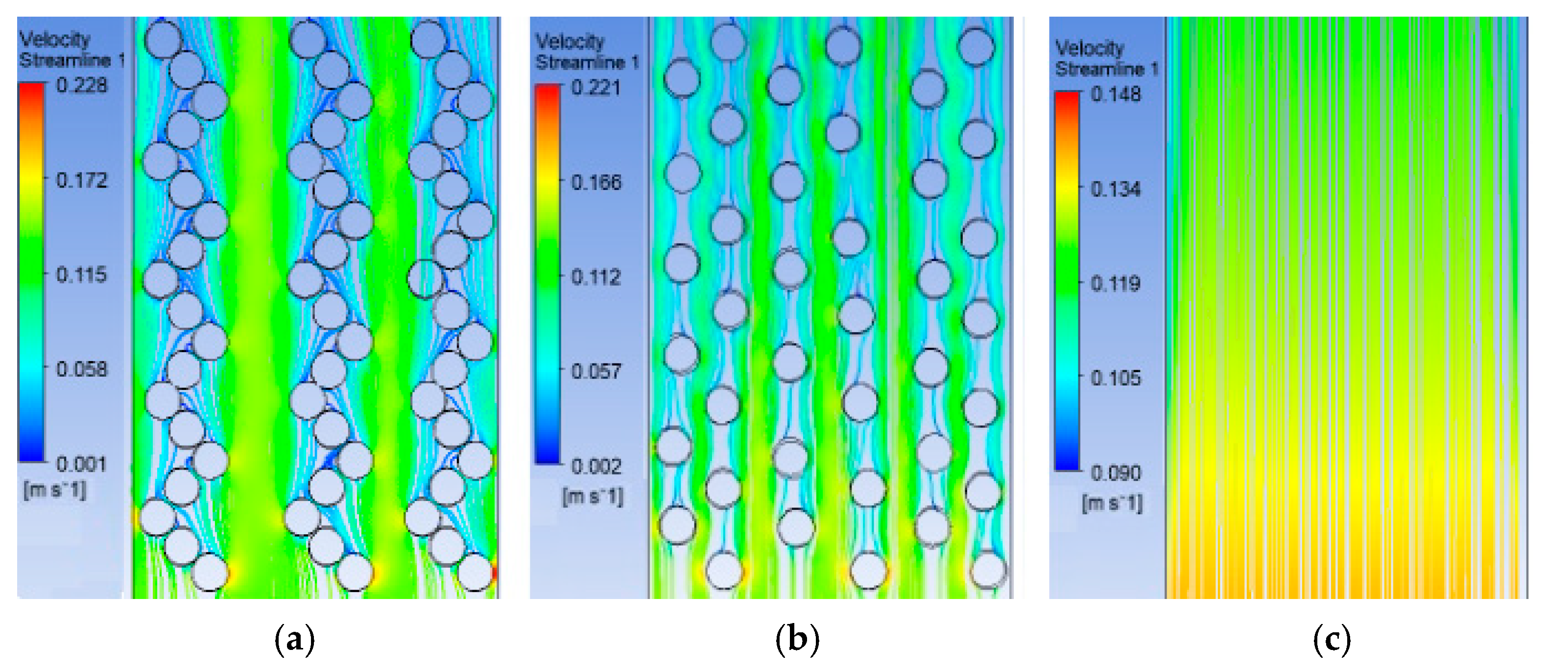
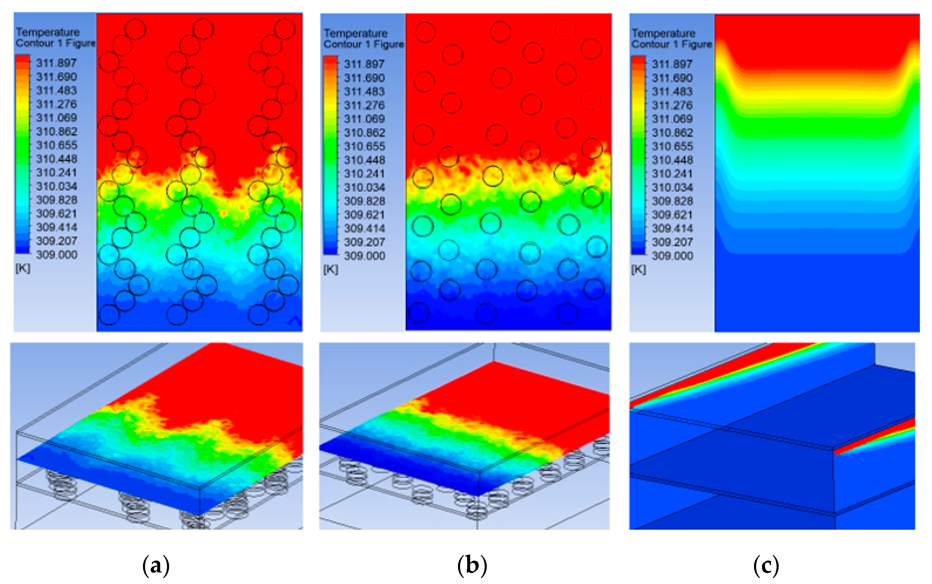
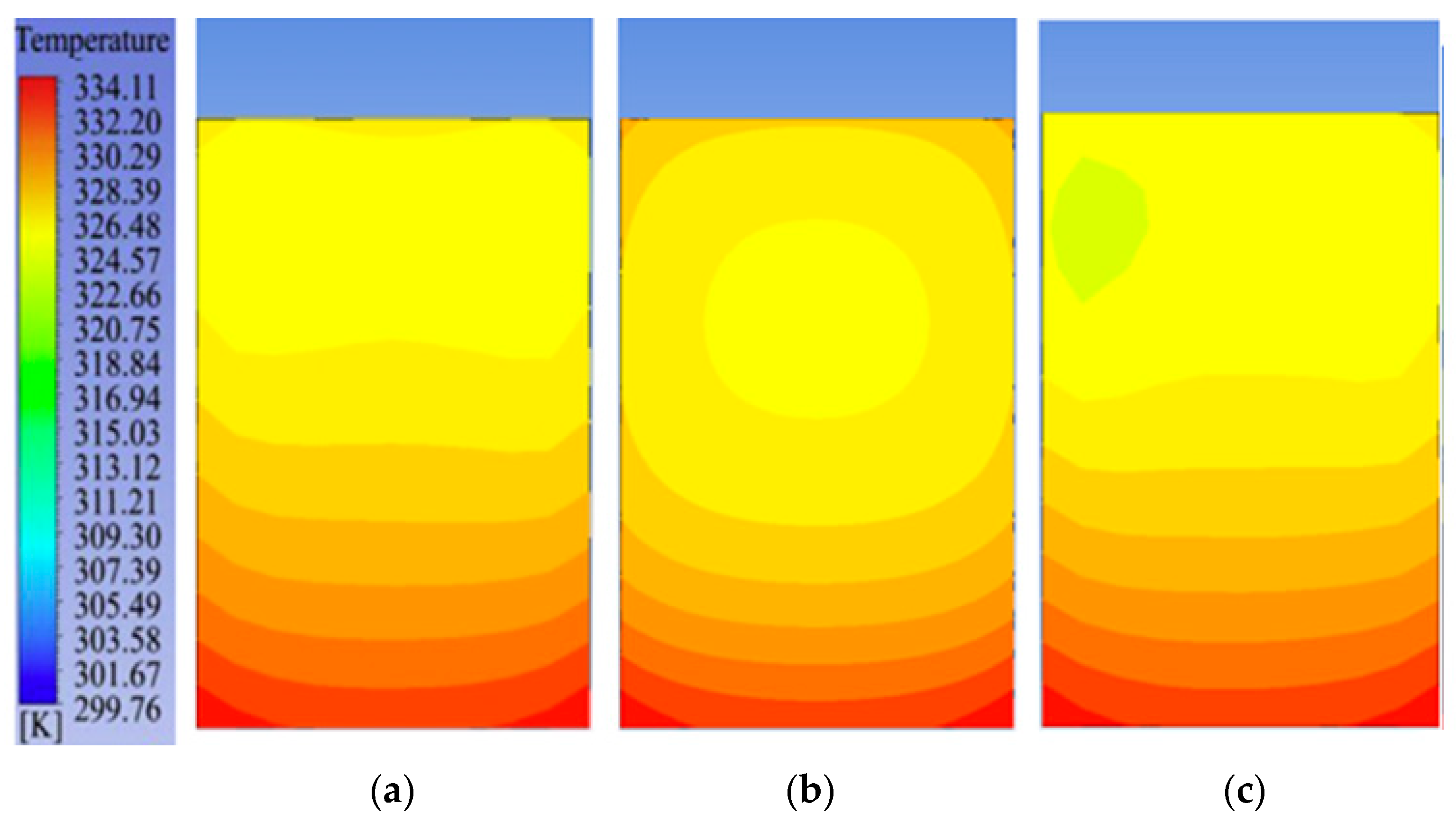
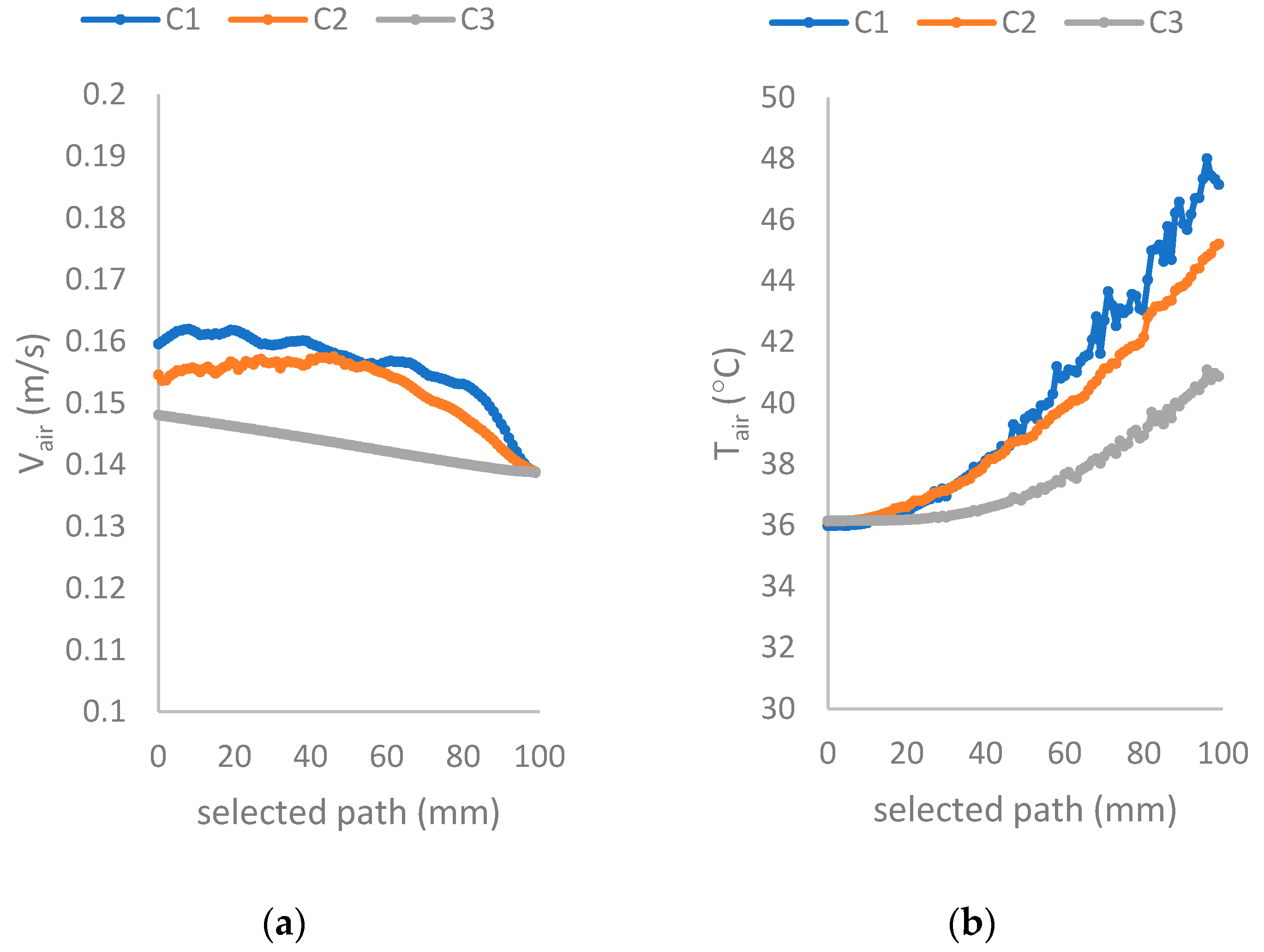
4.1. Numerical Results

The results of numerical study are given in this section. In Figure 6 and Figure 7, a YZ plane is created 2 cm above the obstacles. Velocities of different absorber surfaces are given in Figure 6. The velocity streamlines are given in Figure 7. The velocity contours of the complex absorber surface (C1), the less complex absorber surface (C2), and the smooth absorber surface (C3) are respectively presented in the subfigures of Figure 6a–c.
When the C1 type collector was used, the maximum speed was obtained as 0.19 m/s, while when the C2 type collector was used, the air speed was determined as 0.186 m/s. This shows that the air velocity is slightly higher on the more complex surface compared to the less complex surface. This is because elements that add more complexity increase the turbulence value. Obstacles to the flow increase the velocity by causing the formation of vortices in the flow. The collector type without any elements on it, namely C3, has the lowest velocity distribution on the surface, which is already an expected situation. It can be concluded that adding surface-enhancing elements causes a nearly 35% increase in air velocity.
The temperature values of the three absorber surfaces, C1, C2, and C3, are respectively shown in Figure 8a–c. As can be clearly seen in the figure, the maximum temperature is the same in all three cases. However, the collector area where the maximum temperature is effective is largest in C1 and smallest in C3. In other words, the temperature effects appear towards the exit of the channel for C3 type collector, but appear at the center parts of the channel for C1 and C2 types. This is an indication that the stainless steel scourers not only create turbulence, but also affects temperature distribution. It is also worthy to note that, especially on the complex surface (C1), the temperature in the center region takes the shape of a zigzag and shows a change that is almost proportional to the shape of the array.
The efficiency of the collectors depends on the structure of the solar air heater and the solar irradiance value. The material, shape, and dimensions of the collector affect the performance improvement. Surface-enhancing elements such as fins, obstacles, curved surfaces, and the different shapes given in the literature when placed on the absorber surface increase the temperature and thus increase the efficiency, because they increase the heat transfer area [2,3].
The number and arrangement style of the stainless-steel scourers placed above and below the absorbing surface creates turbulent flow. This provides the highest heat transfer coefficient, the highest absorber temperature, and reduced thermal heat loss. Therefore, the highest efficiency is achieved when C1 is used. On the other hand, C3 has less efficiency than the other collectors. This is because this collector has a flat absorbing surface, and the heat transfer area is smaller than the others.
The temperature contours of the glass surface of the tested surfaces C1, C2, and C3 are respectively presented in Figure 9a–c. Note that the glass surface started to cool earlier on complex surfaces. It cannot be said that the turbulence-enhancing elements on the surface have much effect on the glass surface temperature. However, when you look at the figures carefully, it can be seen that the cooling occurs more uniformly on the C1 surface compared to the other C2 and C3 surfaces.
The velocity and temperature data were collected while considering that a path (line) passes through the center of the channel at a height of 30.4 cm from the bottom and 10.4 cm from the absorber surfaces. The average velocities on that path are given in Figure 10a and the average temperatures are given in Figure 10b. It is observed that the velocity changes almost linearly for the flat absorber surface (C3). In the other cases, (C1 and C2), it follows a fluctuating course along the channel. The average velocity obtained for the C1case is highest of all. Similarly, the highest temperature is obtained for C1.
The comparison graphs are respectively given in Figure 10a,b by means of air velocity and collector exit temperature variations along the selected path, which is already defined in the previous paragraph. The effect of the scourers can be evaluated by means of the augmentation of the velocity and temperature by comparing the C1 and C2 cases with C3. In the C1-type collector, there is an increase of around 7.2% in air velocity compared to the C3 type. When the air velocity obtained from the C2-type collector is compared to the air velocity obtained from the C3-type collector, an increase of approximately 6.6% is achieved. In terms of temperature, it can be seen that the temperature obtained with the C1-type collector increases by 7.4% compared to the C3-type collector, and the increase is 5% with the C2-type collector.
The efficiency is the last extracted result from the numerical analysis. By using Equations (1) and (2), the efficiency was calculated. It should be noted that, for the numerical analysis, the heat flux and radiation values were kept constant, as mentioned in the previous section. The efficiency values for the collector types C1, C2, and C3 were respectively found to be 74%, 67% and 55%. It can be seen that the C1 case has the highest efficiency, meaning the arrangement style of the stainless-steel scourers affects the efficiency directly. Another point that is obvious when looking at the efficiency values is that the efficiency of the flat-plate collector type has the lowest value. When the C1-type collector is used, the efficiency increases 1.34 times compared to the flat-plate collector. Similarly, when the C2-type collector is used, the efficiency increases 1.21 times.

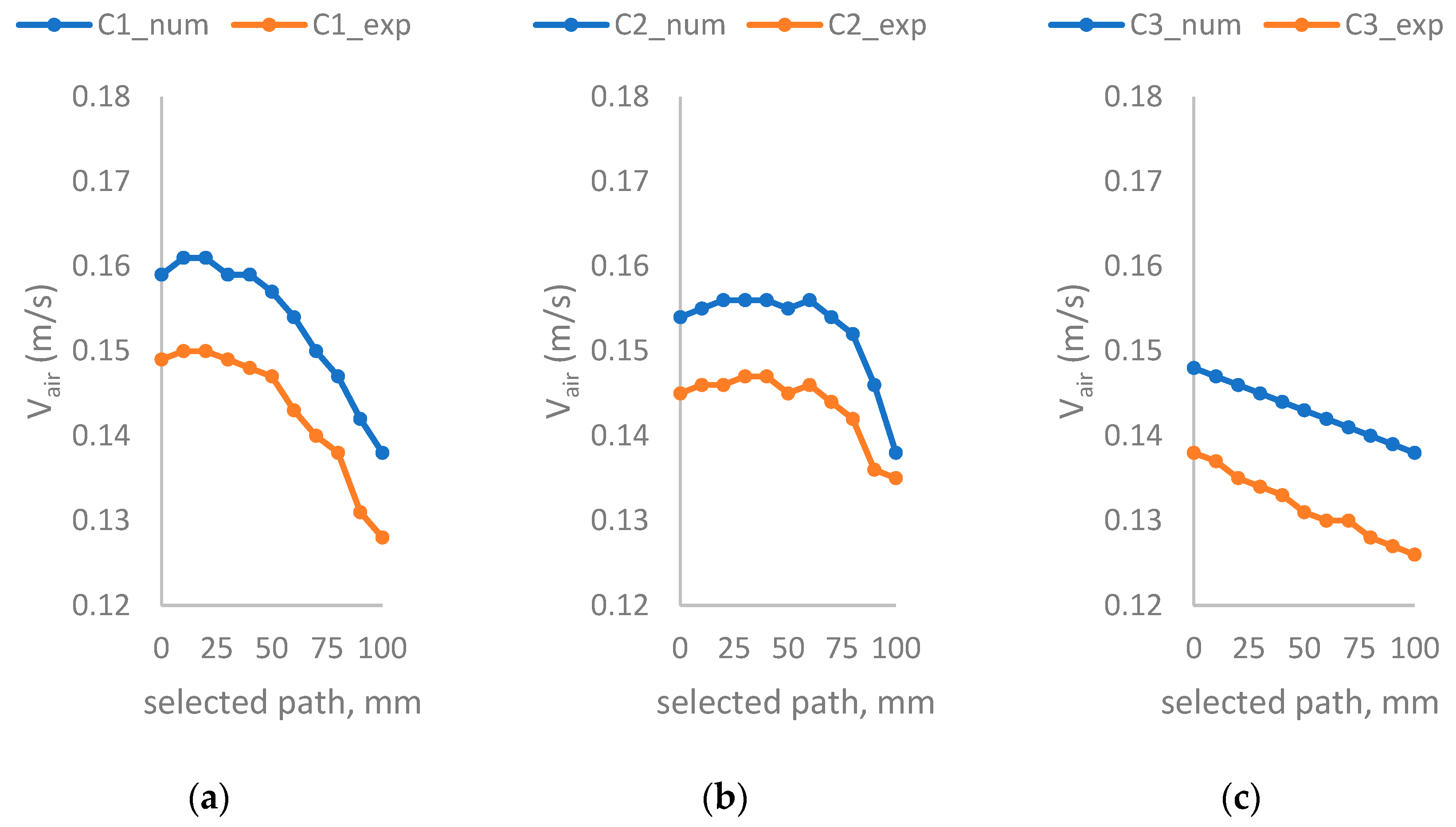
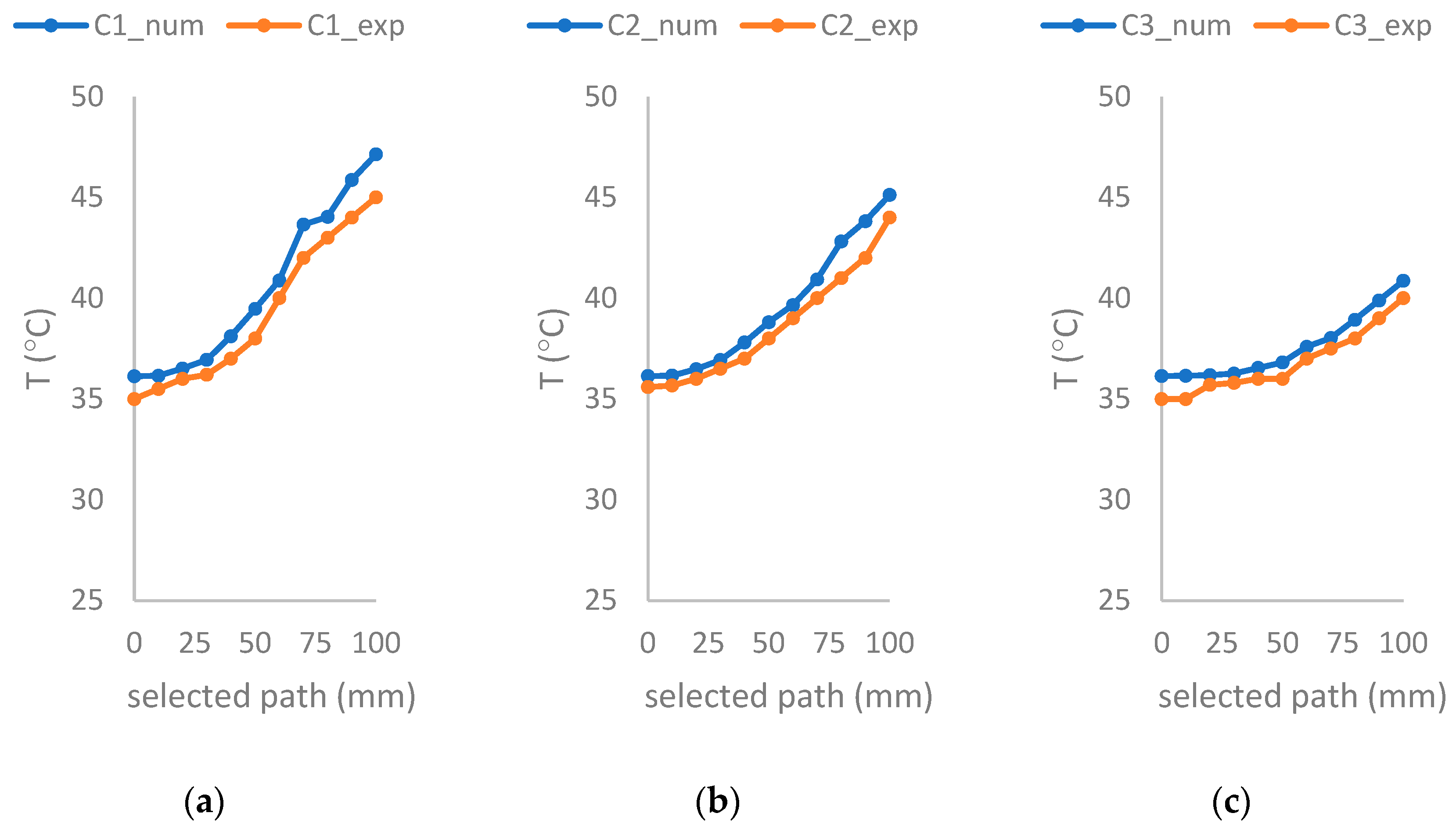
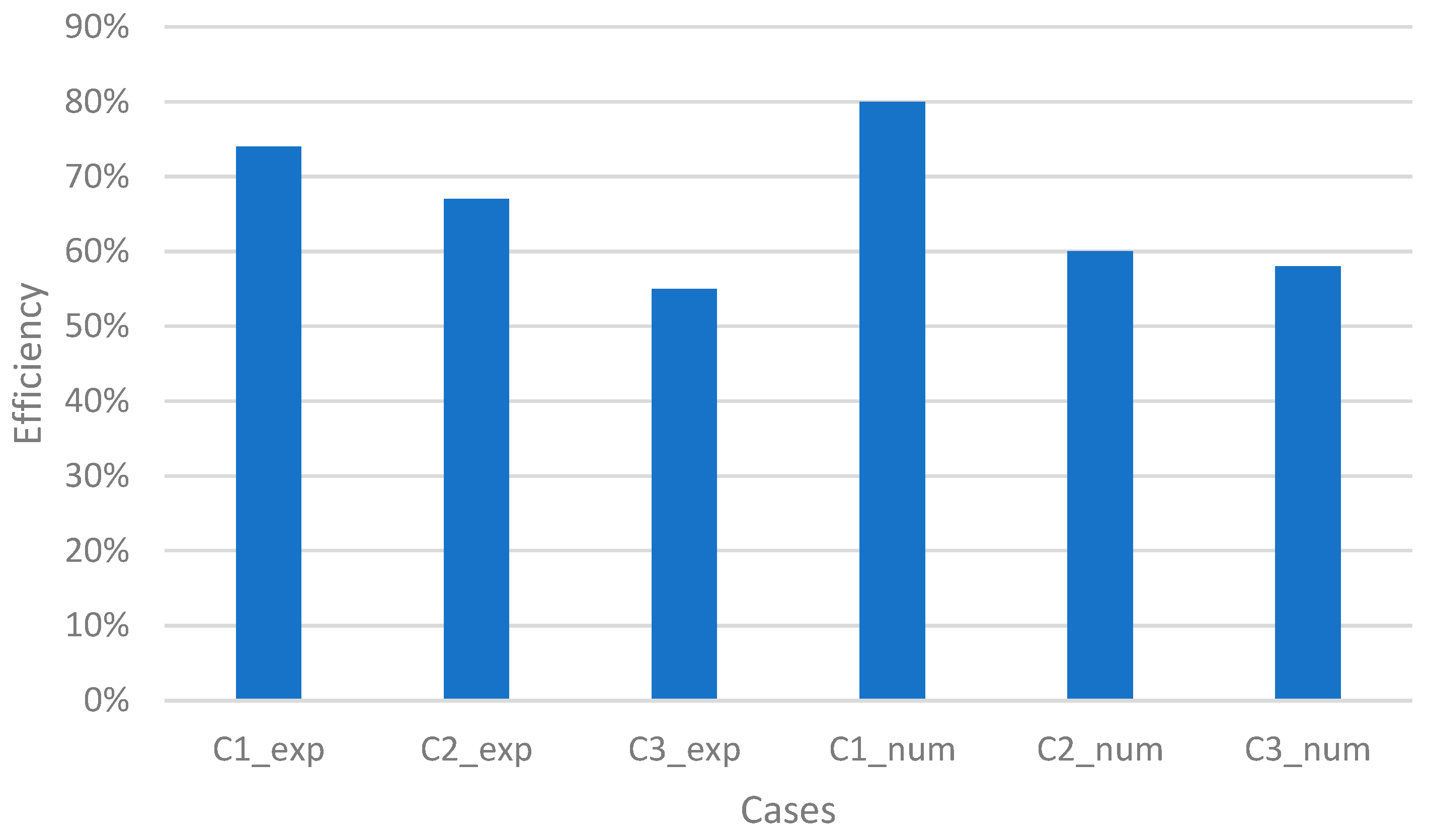
4.2. Comparisons of Numerical and Experimental Results

The comparisons of the numerical results and the experimental results are presented in this section. Figure 11 and Figure 12 are plotted to show the numerical and experimental results by means of air velocity and exit temperature. The quantitate values are also listed in Table 2 to better show the comparison. Figure 13 shows the comparison of experimentally found efficiencies and the numerically found ones.
Before discussing the results presented in Figure 11, Figure 12 and Figure 13 and Table 2, it should be declared that the numerical analysis and the experimental tests have the similar trends for all cases. Hence, a good agreement is achieved between numerical and experimental analyses.
According to Figure 11 and Figure 12, the average difference between the experimental and numerical velocities for the C1-, C2-, and C3-type collectors are, respectively, 7.26%, 6.25%, and 8.57%. The average differences between the experimental and numerical temperatures for the C1-, C2- and C3-type collectors are, respectively, 2.99%, 2.27%, and 2.07%.
As a final result, the efficiencies were calculated using both the measured values and the predicted numerical values. The efficiencies are shown in a bar graph in Figure 13. It is evident from the graph that the most efficient case is the C1 case, and the least efficient case is the C3 case. The agreement between the numerical and experimental efficiency values is within the acceptable range. The difference can be explained by the uncertainties.

4.3. Comparison to the Literature

Finally, attention is here turned to the comparison of the numerical results to the literature. The performance characteristics for the surface-enhancing elements organized in the shape of an arc in a duct with an aspect ratio of 11 were experimentally investigated by Sethi and Thakur [18], and it was shown that the size and geometry of the elements have great effect on the heat transfer. The effectiveness of flat and dimpled SAHs in turbulent flow conditions was found by Bhushan et al. [19].
In the case of flat and dimpled SAHs, it was determined that the greatest difference in temperature is 10 °C for the air mass flowrate of 0.05 kg/s. Lin et al. [20] have experimentally and numerically studied the thermal performance of a solar air collector with a corrugated absorber. Numerical simulations have shown that the air temperature can be improved effectively by using the surface-enhancing elements. Maximal temperature differences between the inlet air and outlet air of 14.24 °C, 23.27 °C, and 26.11 °C were observed, respectively, for three absorber cases that were tested.

5. Conclusions

In this study, a numerical analysis of a solar air collector system whose absorber surface included porous stainless-steel scourers was analyzed. Toward this aim, a 3D CFD analysis and an experimental test for verification are presented. The measured values of air flow rate and inlet temperatures from the experimental work were used as the boundary conditions in the numerical study. The air flow section from the inlet to the outlet of the designed collector, namely the solution domain, was created in 3D with a one-to-one scale. Stainless-steel scorers were placed on two absorber surfaces, called C1 and C2. A surface without any element was also modeled for comparison (C3).
The numerical analysis was performed using ANSYS-CFX-R18.2 The air velocity and temperature were compared to the values measured in the experimental work. The efficiency was also calculated using experimental measurements and numerical results. It has been shown that there is a good agreement between each method.
The addition of stainless-steel scourers to the absorber surface has an impact on temperatures, velocities, and efficiency. While an efficiency of around 80% was achieved on surfaces with stainless-steel scourers, the efficiency remained around 55% in the flat-plate collector. Furthermore, the highest air temperature and air velocity were obtained in the collector with the most complex surface. This is because the stainless-steel scourers placed on and below the absorbing surface create turbulent flow by enhancing the surface area. This results in a high heat transfer coefficient, a high sink temperature, and reduced thermal heat loss. On the other hand, compared to the case where stainless-steel scourers were used on the absorber surface, lower temperature and velocity values were found in the flat-plate collector case where no elements were used.
The porosity values of the scourers used in this study could not be determined exactly and their dimensions were fixed. The effect of parameters such as size and porosity should be investigated in future studies. Moreover, even if it is known to be economically cheap, its use in the solar industry should be encouraged by a good economic analysis.

Author Contributions

Conceptualization, O.F.C.; methodology, F.O. and O.F.C.; data curation; A.T. and C.K.; writing—original draft preparation, N.C.; writing—review and editing; N.C. All authors have read and agreed to the published version of the manuscript.

Funding

This research received no external funding.

Institutional Review Board Statement

Not applicable.

Informed Consent Statement

Not applicable.

Data Availability Statement

The datasets generated during and/or analyzed during the current study are not publicly available as the Turkish language is used in all files, but they are available from the corresponding author upon reasonable request.

Conflicts of Interest

The authors declare no conflict of interest.

References

  1. Vengadesan, E.; Senthil, R. A Review on recent developments in thermal performance, enhancement methods of flat plate solar Air Collector. Renew. Sustain. Energy 2020, 134, 110315. [Google Scholar] [CrossRef]
  2. Kishk, S.S.; ElGamal, R.A.; ElMasry, G.M. Effectiveness of recyclable aluminum cans in fabricating an efficient solar collector for drying agricultural products. Renew. Energy 2019, 133, 307–316. [Google Scholar] [CrossRef]
  3. Yadav, A.S.; Shukla, O.P.; Sharma, A.; Khan, I.A. CFD analysis of heat transfer performance of ribbed solar air heater. Mater. Today Proc. 2022, 62, 1413–1419. [Google Scholar] [CrossRef]
  4. Njomo, D. Unglazed selective absorber solar air collector: Heat exchange analysis. Heat Mass Transf. 2000, 36, 313–317. [Google Scholar] [CrossRef]
  5. Chaube, A.; Sahoo, P.K.; Solanki, S.C. Analysis of heat transfer augmentation and flow characteristics due to rib roughness over absorber plate of a solar air heater. Renew. Energy 2006, 31, 317–331. [Google Scholar] [CrossRef]
  6. Pashchenko, D.I. ANSYS Fluent CFD modeling of solar air-heater thermo-aerodynamics. Appl. Sol. Energy 2018, 54, 32–39. [Google Scholar] [CrossRef]
  7. Karim, M.A.; Hawlader, M.N.A. Performance investigation of flat plate, v-corrugated and finned air collectors. Energy 2006, 31, 452–470. [Google Scholar] [CrossRef]
  8. Ammar, M.; Mokni, A.; Hatem, M.; Philippe, B. Numerical analysis of solar air collector provided with rows of rectangular fins. Energy Rep. 2020, 6, 3412–3424. [Google Scholar] [CrossRef]
  9. Badiei, Z.; Eslami, M.; Jafarpur, K. Performance improvements in solar flat plate collectors by integrating with phase change materials and fins: A CFD modeling. Energy 2020, 192, 116719. [Google Scholar] [CrossRef]
  10. Panchal, H.; Sohani, A.; Nguyen, N.V.; Shoeibi, S.; Khiadani, M.; Huy, P.Q.; Hoseinzadeh, S.; Kabeel, A.E.; Saboor, S.; Cuce, E. Performance evaluation of using evacuated tubes solar collector, perforated fins, and pebbles in a solar still—Experimental study and CO2 mitigation analysis. Environ. Sci. Pollut. Res. 2023, 30, 11769–11784. [Google Scholar] [CrossRef] [PubMed]
  11. Saxena, A.; Cuce, E.; Tiwari, G.N.; Kumar, A. Design and thermal performance investigation of a box cooker with flexible solar collector tubes: An experimental research. Energy 2020, 206, 118144. [Google Scholar] [CrossRef]
  12. Ozgen, F.; Dayan, A. Energy analysis of a solar air heater with an absorber plate made of porous material. Therm. Sci. 2021, 23, 333–337. [Google Scholar] [CrossRef]
  13. Ozgen, F.; Dayan, A. Design of an air solar collector with an absorber plate made of porous material. Int. J. Innov. Eng. Appl. 2021, 5, 11–17. [Google Scholar]
  14. Yahya, S.G.; Mao, X.; Jaworski, A.J. Experimental investigation of thermal performance of random stack materials for use in standing wave thermoacoustic refrigerators. Int. J. Refrig. 2017, 75, 52–63. [Google Scholar] [CrossRef]
  15. Abduljalil, A.S.; Yu, Z.; Jaworski, A.J. Selection and experimental evaluation of low-cost porous materials for regenerator applications in thermoacoustic engines. Mater. Des. 2011, 32, 217–228. [Google Scholar] [CrossRef]
  16. Kline, S.J.; McClintock, F.A. Describing Uncertainties in Single-Sample Experiments. Mech. Eng. 1953, 75, 3–8. [Google Scholar]
  17. Menter, F.R. Two-equation eddy-viscosity turbulence models for engineering applications. AIAA J. 1994, 32, 1598–1605. [Google Scholar] [CrossRef]
  18. Sethi, M.; Thakur, N.S. Correlations for solar air heater duct with dimpled shape roughness elements on absorber plate. Sol. Energy 2012, 86, 2852–2861. [Google Scholar] [CrossRef]
  19. Bhushan, A.; Kumar, R.; Perwez, A. Experimental investigations of thermal performance for flat and dimpled plate solar air heater under turbulent flow conditions. Sol. Energy 2022, 231, 664–683. [Google Scholar] [CrossRef]
  20. Lin, W.; Ren, H.; Ma, Z. Mathematical modelling and experimental investigation of solar air collectors with corrugated absorbers. Renew. Energy 2020, 145, 164–179. [Google Scholar] [CrossRef]
Figure 1. Experimental setup.
Applsci 14 02629 g001
Figure 2. Absorber surfaces [12,13]; (a) C1, (b) C2, (c) C3, (d) collector with scourers, (e) flat plate collector.
Applsci 14 02629 g002
Figure 3. Collector dimensions and boundary conditions with C1 case.
Applsci 14 02629 g003
Figure 4. Mesh accuracy analysis.
Applsci 14 02629 g004
Figure 5. Mesh structure of the (a) C1 and (b) C2 cases.
Applsci 14 02629 g005
Figure 6. Velocity contours on each absorber surface; (a) C1, (b) C2, (c) C3.
Applsci 14 02629 g006
Figure 7. Velocity streamlines on each absorber surface; (a) C1, (b) C2, (c) C3.
Applsci 14 02629 g007
Figure 8. Temperature contours on each absorber surface; (a) C1, (b) C2, (c) C3.
Applsci 14 02629 g008
Figure 9. Contours of glass temperatures on each absorber surface; (a) C1, (b) C2, (c) C3.
Applsci 14 02629 g009
Figure 10. Variation of (a) Velocity and (b) Temperature along a selected path.
Applsci 14 02629 g010
Figure 11. Comparison of experimental and numerical air velocities; (a) C1, (b) C2, (c) C3.
Applsci 14 02629 g011
Figure 12. Comparison of experimental and numerical temperatures; (a) C1, (b) C2, (c) C3.
Applsci 14 02629 g012
Figure 13. Comparison of experimental and numerical efficiencies.
Applsci 14 02629 g013
Table 1. Properties of the glass surface and air.
ρ (kg/m3)Cp (J/kgK)k (W/mK)ν (m2/s)
Glass surface30005001.8-
Air1.13610070.0261.655 × 10−5
Table 2. Air velocities and temperatures along the selected path.
PathC1_numC2_numC3_numC1_expC2_expC3_exp
Air Velocities, (m/s)
00.1590.1540.1480.1450.1490.138
100.1610.1550.1470.1460.150.137
200.1610.1560.1460.1460.150.135
300.1590.1560.1450.1470.1490.134
400.1590.1560.1440.1470.1480.133
500.1570.1550.1430.1450.1470.131
600.1540.1560.1420.1460.1430.13
700.1500.1540.1410.1440.140.13
800.1470.1520.1400.1420.1380.128
900.1420.1460.1390.1360.1310.127
1000.1380.1380.1380.1350.1280.126
Temperatures (°C)
036.1336.1436.1435.5935.0035
1036.1536.1636.1535.6735.535
2036.5136.4836.18363635.7
3036.9436.9336.2636.536.235.8
4038.1137.836.54373736
5039.4738.8136.81383836
6040.8839.6637.59394037
7043.6540.9338.02404237.5
8044.0342.8138.93414338
9045.8643.8239.89424439
10047.1445.1240.86444540
Disclaimer/Publisher’s Note: The statements, opinions and data contained in all publications are solely those of the individual author(s) and contributor(s) and not of MDPI and/or the editor(s). MDPI and/or the editor(s) disclaim responsibility for any injury to people or property resulting from any ideas, methods, instructions or products referred to in the content.

