Article

An Analysis of the Effect of Hall Thruster Plumes on Surface Charging of a Complex Spacecraft Structure

1
National Space Science Center, Chinese Academy of Sciences, Beijing 100190, China
2
University of Chinese Academy of Sciences, Beijing 100049, China
3
Shanghai Institute of Satellite Engineering, Shanghai 201109, China
4
Shanghai Academy of Spaceflight Technology, Shanghai 201109, China
*
Author to whom correspondence should be addressed.
Appl. Sci. 2024, 14(6), 2650; https://doi.org/10.3390/app14062650
Submission received: 28 December 2023 / Revised: 18 March 2024 / Accepted: 20 March 2024 / Published: 21 March 2024
(This article belongs to the Special Issue Recent Advances in Space Propulsion Technology)

Abstract

:

Featured Application

The present study can be applied to the study of the influence of a Hall thruster plume on the spacecraft surface.

Abstract

This article aims to conduct an in-depth investigation into the environmental impact of Hall thruster plumes on spacecraft surface charging. The non-uniform plasma plume generated by Hall thrusters may trigger charging and discharging effects, making the assessment of surface charging risks crucial. Through numerical simulations using SPIS system, this study evaluates the surface charging characteristics of a complex spacecraft in orbit, simulating the effects of turning on and off the thrusters, as well as varying distances between the thrusters and the spacecraft. The simulation demonstrates that turning on the thrusters significantly affects spacecraft charging, reducing the potential difference between spacecraft surfaces from 3740 V to 19.2 V, effectively alleviating electrostatic discharge on the spacecraft surface. The closer the thruster is to the spacecraft, the more CEX ions are collected on the surface, influenced by the beam ions, resulting in a surface potential change of 1.3 V, with minor effects on surface potential but contributing to increased deposition contamination on the spacecraft surface.

1. Introduction

The Hall thruster, advanced propulsion technology, is increasingly favored for diverse space exploration missions. This preference stems from its attributes, including a lightweight design, high specific impulse, robust reliability, and extended lifespan [1,2]. Nevertheless, its plume exhibits non-uniform plasma characteristics, potentially causing various issues when interacting with the satellite’s near-field space environment. These issues encompass interactions with the near-field plasma, electromagnetic, and thermal environments. These interactions may result in adverse effects on the spacecraft, including charging and discharging effects, deposition contamination, sputtering corrosion, and other detrimental impacts [3]. These effects, in turn, impact the performance of spacecraft surface materials and disrupt the normal operation of the payload. Notably, spacecraft charging and discharging effects are prominent, contributing to approximately 50% of spacecraft anomalies in the space environment. Consequently, evaluating surface charging risks is crucial [4,5]. The effects of spacecraft charging and discharging reflect the charging conditions of satellite platforms within specific orbits, moments, materials, and structural designs. Due to the non-direct applicability of different structures and platforms, it becomes essential to analyze the charging of a specific spacecraft configuration.
Apart from a thorough investigation into the plume-induced charging effects, this study specifically focuses on how the Hall thruster plume affects spacecraft surface charging at various locations, particularly examining variations under different mission conditions.
This paper aims to enhance our comprehension of the potential environmental impacts of these thrusters in practical scenarios. Conducting a comparative analysis of the plume effects produced by thrusters at distinct locations on spacecraft surface charging allows us to develop a more thorough understanding of their behavioral characteristics in the space environment. This not only unveils the intricate interactions between the plume and the spacecraft but also furnishes a comprehensive guide for future spacecraft design and selection tailored to specific missions. Hence, this study not only underscores the influence of thruster plumes on spacecraft charging but also integrates an in-depth exploration of spacecraft surface charging by thrusters at various positions, offering a more dependable assurance for the successful execution of space exploration missions and making a substantial contribution to the advancement in future propulsion technologies.
In this paper, we utilize SPIS (Spacecraft Plasma Interaction System) to simulate the surface charging potential, surface current, and distribution of various particles in the thruster plume of a spacecraft with a complex satellite structure. This allows us to comparatively analyze the impact of the thruster plume on spacecraft surface charging, as well as the effects of thrusters at different positions on surface charging and the distribution of various particles in the surrounding environment.

2. Theoretical Models

2.1. Surface Charging Theory Model

2.1.1. Equation for Current Balance

Spacecraft surface charging is a complex process influenced by various factors, including the space plasma environment, surface material properties, illumination conditions, incident particle energy, etc. The equilibrium of spacecraft surface current inflow and outflow occurs when the potential reaches a steady state. During this equilibrium, the potential on the spacecraft surface reaches a stable state. While in orbit, the spacecraft surface experiences constant impacts from charged particles in the space plasma environment, leading to electronic charging current and ion charging current on the spacecraft surface. Higher-energy charged particles prompt the release of secondary electron current and backscattered electron current from the spacecraft surface materials. Sunlight exposure to the surface material excites photoelectrons. Simultaneously, the charge accumulated on the surface material migrates to neighboring material surfaces and inside the spacecraft, resulting in current leakage. This leakage current contributes to maintaining an overall charge balance by transferring excess charge to the spacecraft interior and surrounding surfaces, mitigating the surface charging effect. To assess the impact of the Hall thruster plume on spacecraft surface charging, we must consider both the returning ion currents in the thruster plume and the neutralizing electron currents from the hollow cathode [6]. These factors significantly influence the dynamic characteristics of the charging effect, introducing complexity to the spacecraft surface charging behavior. Figure 1 depicts spacecraft surface currents and the current balance equation under a balanced surface potential [7]:
I e + I Xe = I i + I s + I b + I ph + I 1 + I ne
where I e is the incident electron current; I i is the incident ion current; I s is the secondary electron current; I b is the backscattered electron current; I ph is the photoelectron current, and the consideration involves the photoelectron current I e - ph emitted by the material and the photoelectron current I i - ph returning to the material surface, influenced by the electric potential in the space environment; I 1 is the leakage current; I Xe is the ion current generated by the thruster, including the preexisting ion currents, the ion currents I Xe + and I Xe + + , as well as the ion current I CEX _ Xe + generated by charge exchange (CEX) collisions; and I ne is the neutralization electron current.
The plume region’s small Debye length in comparison to the characteristic length enables it to satisfy the quasi-neutral approximation condition. This condition is influenced by the surface potential, and the electron flux on the spacecraft surface is computed using the following electron collection model [8]:
J e = J e 0 exp e ϕ s ϕ p T e ,   if   ϕ s ϕ p < 0 , J e = J e 0 1 + e ϕ s ϕ p T e ,   if   ϕ s ϕ p > 0 ,
where J e 0 = e n e e T e / 2 π m e is the thermal current density of the plasma within the grid, n e is the electron density, m e is the mass of the electron, ϕ s is the potential at the collecting surface, ϕ p is the plasma potential, T e is the electron temperature, T e being expressed in energy units, and e is the elementary charge. In the quasi-neutral approach, given the absence of sheath layers, the current ( J e 0 ) is directly calculated at the surface nodes, and the current calculation conforms to the Orbital Motion Limited law [9]. The ion current is established by computing the number of macroscopic ion particles impacting a specified surface. This count is subsequently converted into current, taking into account the weight and charge of the macroscopic ion particles.
SPIS simulates the surface charging phenomenon by first calculating the distribution of electrons and ions. To enhance computational speed and simulation accuracy, a particle mixing model is adopted, treating electrons as a fluid and ions as kinetic particles. The dynamic process of plasma electrons under the self-consistent electric field is computed through the Vlasov–Poisson equation [10], while the dynamic process of ions is calculated using the Boltzmann–Poisson equation. Moreover, due to the high plasma density in the plume and the extensive computations involved, the Particle In Cell–Monte Carlo Collisions (PIC-MCC) method is employed. This method introduces the concept of macro-particles, where the motion of macro-particles is represented by a subset of them rather than the actual motion of charged particles. In the PIC method, particles reside within grid cells, and it requires assigning weights to the volume of particles with different energies within the grid cell to distribute charges to surrounding grid points, thereby representing the total charge of the macro-particle, and the motion equation of macro-particles is obtained through the combination of Maxwell’s equations, the force relationship of macro-particles in electromagnetic fields, and Vlasov–Poisson, which is represented as
M a d v n d t = Q a E + v n × B d r n   d t = v n 2 ϕ = ρ ε 0 E = ϕ
where M a is the mass of particles composing a macro-particle, v n is the speed of the macro-particle, Q a is the total charge of a macro-particle, E is the electric field intensity, B is the magnetic field intensity, r n is the travel distance of the macro-particle, ϕ is the potential, ρ is the charge density, ε 0 is the vacuum dielectric constant.

2.1.2. Potential Solver

The Debye length of the plume region being small relative to the characteristic length ensures that the plume region satisfies the quasi-neutral approximation condition. In this context, the neutralizer electrons are treated as isothermal fluid species. Their densities on the simulation mesh are determined by the local plasma potentials, following the Boltzmann relation:
n e = n ref e e ϕ p ϕ r e f T e
where ϕ p is the plasma potential, ϕ ref represents the plasma potential at the grid point, and e is the elementary charge. n ref represents the electron density at the grid point, where it is simultaneously a predetermined fixed value.
According to the ground test and on-orbit data, the electron temperature of the thruster plasma plume is non-isothermal. Therefore, when calculating the local plasma potential for the non-isothermal fluid, it is necessary to refer to the non-isothermal model to obtain the corresponding values. Equation (5) represents the non-isothermal model, and Equation (6) represents the local plasma potential of the non-isothermal fluid [11]:
T e n e 1 γ = C
ϕ p = γ T ref e ( γ 1 ) n i n ref γ 1 1 + ϕ ref
where C is a constant, and γ is a temperature-dependent coefficient; when γ = 1, it means an isothermal case, and when γ = 5/3, it means adiabatic plasma.

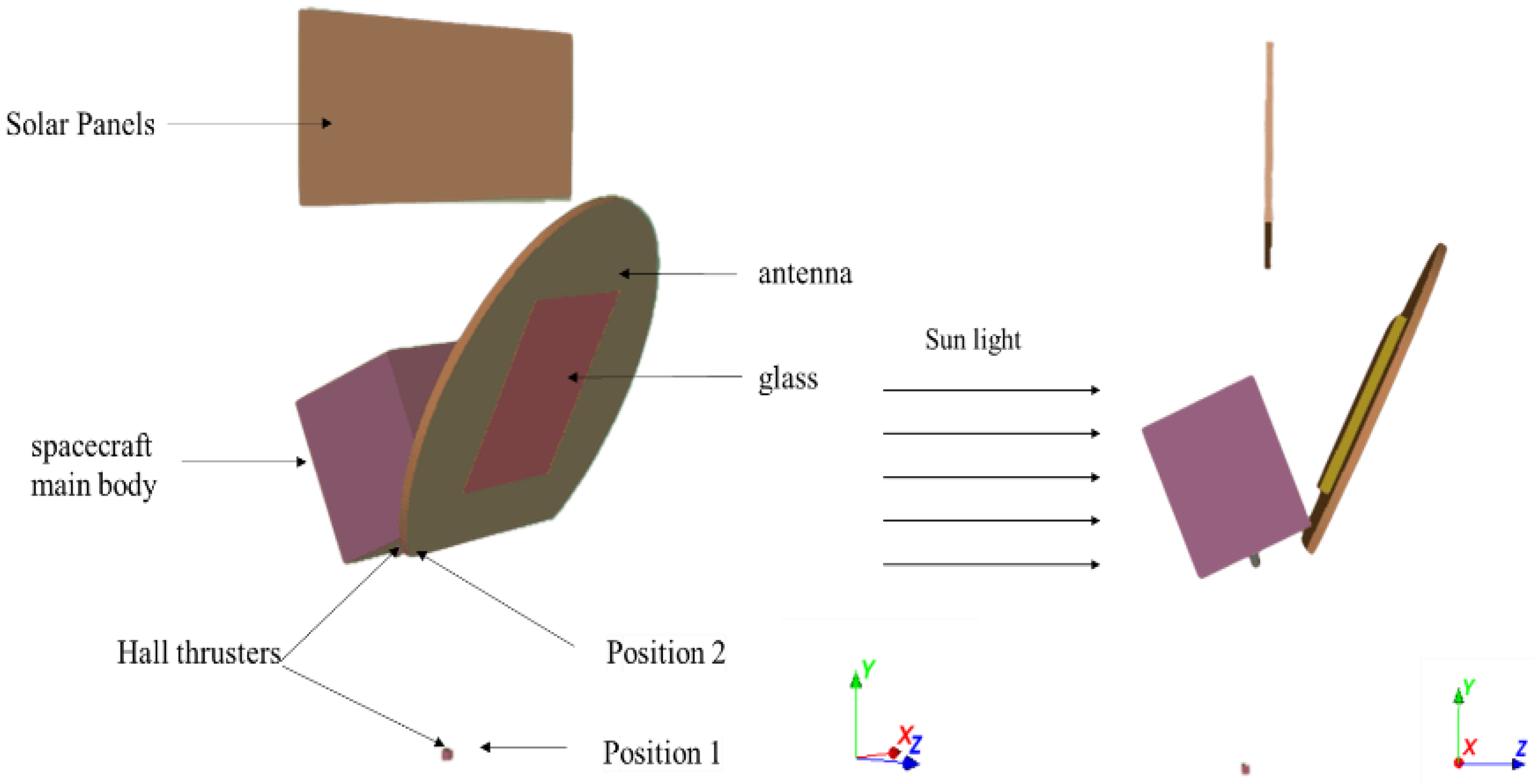
2.2. Geometric Models

To simulate the interaction between the spacecraft and plasma, the numerical model must consider the electrical properties of the surface materials. When evaluating the interplay between the surface and numerical grid density, each spacecraft surface is defined by its outer coating material, represented as a macroscopic electrical node in the model. These surface nodes are connected to the spacecraft ground or other nodes via an equivalent RC circuit. Our calculations prioritize potential differential charges between the dielectric surface and the spacecraft structure, considering factors like dielectric thickness and surface and bulk conductivities.
The spacecraft features a complex structure, consisting of the spacecraft main body, a large curved composite material antenna, a sizable solar panel, and Hall thrusters. The spacecraft’s main body is a cube with a side length of 2.5 m. The large curved composite material antennas are composed of various materials, with an exterior consisting of two layers—one layer of carbon fiber and another layer of aluminum film. The interior includes a large glass panel. The dimensions of the solar panels are 7.0 × 2.5 m, with a thickness of 15 cm. The Hall thruster is a cubic structure with a length of 14 cm and a circular outlet surface. It is positioned 5 m away from the spacecraft main body at Position 1 and to the left of the spacecraft main body at Position 2. In the simulations below, unless otherwise emphasized, the thruster is located at Position 1. Figure 2 shows the geometric model of the spacecraft. Due to the glass portion on the antenna, the illumination on the front and back faces varies, prompting the division of the antenna into two nodes. The remaining spacecraft is partitioned into nodes based on functionality and material differences, with each node connected to the satellite’s structural ground via specific circuits. The materials on various surfaces of the spacecraft model, along with the node assignments and the equivalent RC circuit settings, are outlined in Table 1. In the plasma environment, the spacecraft is considered a capacitor, possessing a floating potential relative to the space plasma. The capacitance of a spacecraft typically depends on its materials and volume. In this study, the capacitance value was determined after setting parameters such as spacecraft materials, resistances, and environmental conditions, with the global parameter “exactCSat” set to 1 for computation. The capacitance of the spacecraft was set to 2.0 × 10⁻⁴ F. During the simulation, sunlight is incident from the -Z direction, with the satellite’s -Z face consistently oriented towards the sun. The boundary conditions mainly refer to the plasma boundary within the computational domain. The properties of the plasma within the domain often depend on the numerical settings of the plasma model boundaries and initial conditions, with two types of boundary conditions: plasma boundary conditions and electric field boundary conditions. In this study, the plasma boundary conditions are set to an open boundary, where particles can be injected from or absorbed by the surface. The electric field boundary conditions are set to Fourier boundary conditions.

2.3. GEO Environmental Model

The Geostationary Earth Orbit (GEO orbit) is known for severe spacecraft charging and discharging [12]. This orbit, particularly in the critical region for hot plasma injection in the magnetotail, where the rate of hot plasma injection is directed towards Earth, results in the accumulation of various positive and negative charges on the Earth-facing side of satellites. This accumulation triggers the phenomenon of high-voltage negative charging, posing potential serious safety hazards. GEO orbits not only contain a substantial amount of low-temperature plasma but are also exposed to high-flux thermal plasma generated by solar storms, geomagnetic storms, geomagnetic substorms, and other activities. The danger is especially pronounced in the extreme conditions induced by geomagnetic substorms, where particles with energies ranging from a few to several hundred keV are present [13]. In order to provide a more accurate depiction of the plasma environment in the GEO orbit, it is necessary to employ a double Maxwell distribution. This distribution effectively integrates the effects of plasma at different energy levels, contributing to a comprehensive understanding of the charging behavior of the spacecraft in the complex dynamics of GEO orbit plasma. The expression for the distribution function is as follows [14]:
f = m 2 π 3 2 n 1 k T 1 3 2 exp m v 2 2 k T 1 + n 2 k T 2 3 2 exp m v 2 2 k T 2
The mass of electrons is significantly smaller than that of ions, leading to electron thermal motion velocities much higher than those of ions. Consequently, this results in electron charging currents being greater than ion charging currents. Therefore, in the absence of plume effects, spacecraft surfaces tend to carry a negative charge. Following the guidelines in the European Space Agency’s Space Environment Handbook [15], negative charging risk assessments are typically conducted in extreme and harsh plasma environments, such as those found in GEO, for surface charging evaluations. Table 2 shows GEO extreme plasma environment parameters set for the simulation.

3. Results

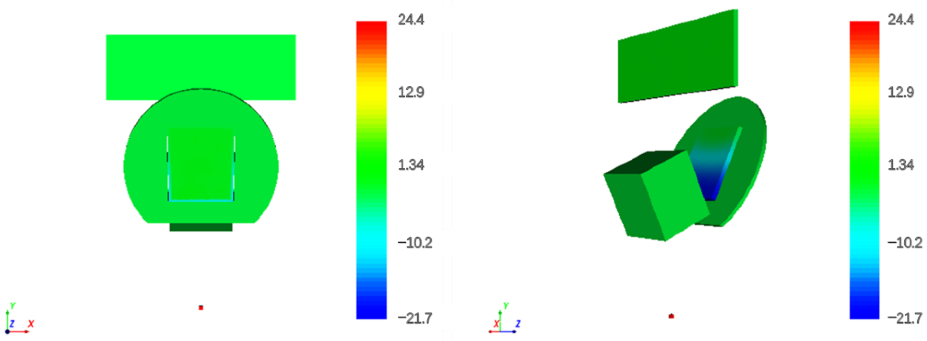
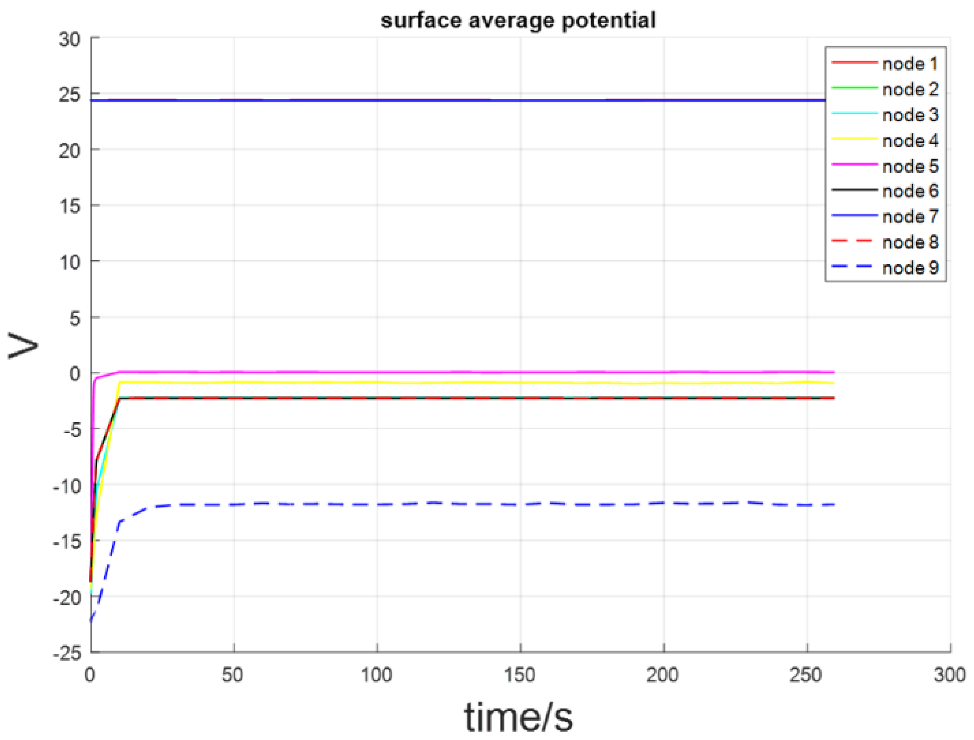
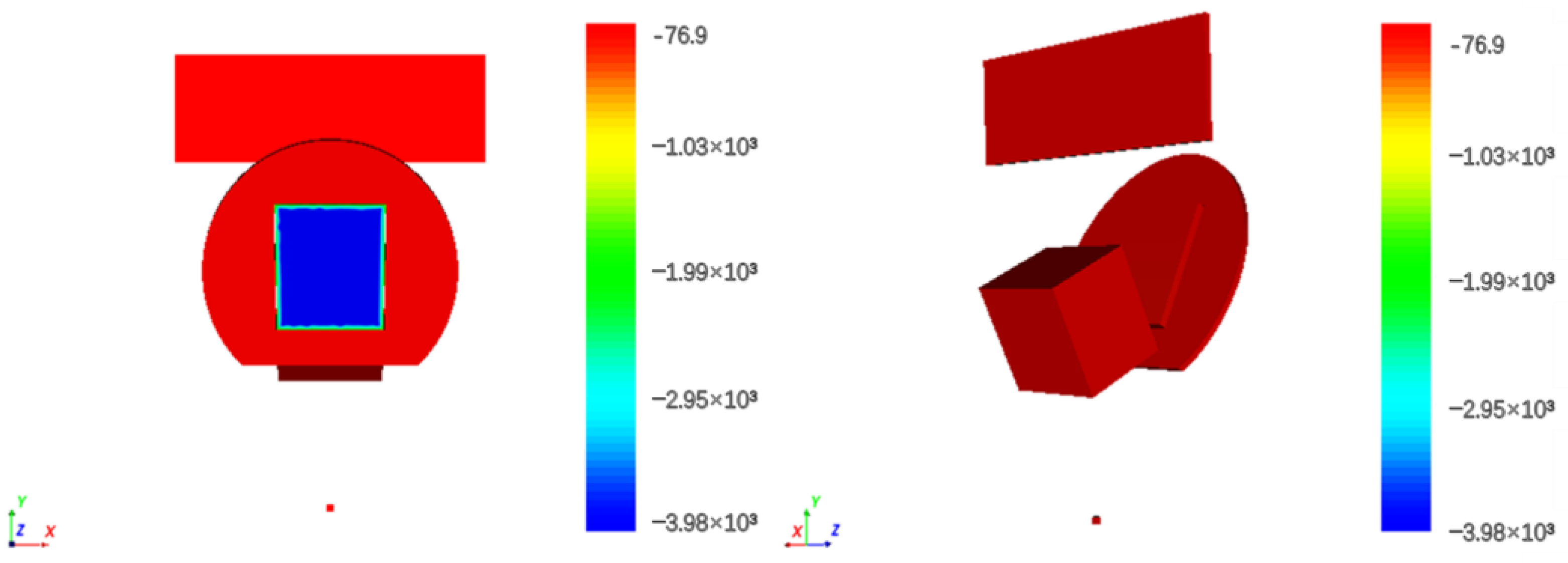
3.1. Impact of Thrusters on Surface Charging and Discharging Effects in Spacecraft

In order to assess the influence of thruster plumes on spacecraft surface charging, an analysis was conducted on the surface charging conditions when the thruster was operational and when it was in a deactivated state.
When the thruster is in operation, Figure 3 and Figure 4 depict the potential distribution of the spacecraft surface and the temporal evolution of the average surface potential at different nodes within the harsh plasma environment of the GEO. In contrast, with the thruster turned off, Figure 5 and Figure 6 portray the potential distribution of the spacecraft surface and the temporal evolution of the average surface potential at various nodes in the harsh plasma environment at the GEO.
Observations indicate that when the thruster is in operation, all node potentials reach an equilibrium state within 30 s, with the surface potential concentrated around −2.4 V. The highest surface potential is on the thruster itself, reaching 24.4 V. The sunlit side of the solar panel (Node 5) maintains a surface potential close to 0 V. On the glass backside (Node 9), the surface potential is negative, peaking at −21.6 V. When the thruster is turned off, after a charging time of 2000 s, except for the sunlit side of the solar panel, the potentials of the other nodes have not reached an equilibrium state. The surface potential continues to gradually rise to higher negative values, with most nodes reaching −140 V. The average surface potential on the sunlit side of the panel is 3.45 V. Node 9 exhibits the highest surface potential, reaching up to −3900 V, with a significant potential difference of 3760 V compared to neighboring areas, making it prone to electrostatic discharge.
To analyze these distinctions, we must consider variations in spacecraft surface charging current and compare the total surface currents of each particle over time under different thruster operating conditions.
It can be seen from Figure 7 that in the two working conditions, there are differences in the total surface currents of various particles on the spacecraft under two operating conditions, including CEX_Xe+ current, photoelectron current, and secondary electron current. When the thruster is off, the incident photoelectron current on the surface of the spacecraft is −4.3 × 10⁻⁴ A, and the incident secondary electron current is −1.64 × 10⁻⁴ A; when the thruster is open, the incident photoelectron current on the surface of the spacecraft is −2.27 × 10⁻⁴ A, and the incident secondary electron current is −7.75 × 10⁻⁵ A, and the CEX_Xe+ current is 4 × 10⁻⁴ A.
Given that the photoelectron and secondary electron currents emitted from the spacecraft surface material remain constant under both operating conditions, the unchanged secondary electron emission coefficient indicates that the interaction of the plume with the spacecraft does not affect the material properties [16]; photoelectrons and secondary electrons typically possess lower energies (~1 eV–~100 eV), slower velocities, and lighter masses. Due to Coulombic interactions among charged particles, low-energy photoelectrons and secondary electrons may be captured by nearby ions. This capture biases the electron orbits toward the direction attracted by surrounding ions, expanding their diffusion range in the simulation domain. The density distribution of photoelectrons under two operating conditions is shown in Figure 8. Consequently, this phenomenon reduces the number of photoelectrons and secondary electrons per unit area, resulting in decreased current density. As a consequence, the incident currents of photoelectrons and secondary electrons on the spacecraft surface decrease, leading to a reduction in the spacecraft surface potential. In contrast, backscattered electrons with higher energies exhibit greater velocities, enabling them to more easily overcome the gravitational pull of surrounding ions. This occurs under the influence of the electric field, allowing them to maintain straighter trajectories without being captured.
CEX collisions between fast ions and slow neutral Xe atoms in the beam stream lead to the generation of CEX_Xe+. The low-velocity, low-energy CEX_Xe+ is particularly susceptible to negative potentials on the spacecraft surface, making them more likely to attach to the spacecraft surface. This attachment results in a decrease in the spacecraft surface potential. When the thruster is in operation, the charging effect on the spacecraft is no longer primarily influenced by space plasma but is instead dominated by the return flow of plasma from CEX collisions and its interaction with the spacecraft. This process helps maintain the spacecraft surface potential at a low level, significantly reducing the occurrence of electrostatic discharges between spacecraft surfaces.
When the thruster is operational, the density of neutralizing electron currents on the spacecraft surface is negligible, primarily due to the low energy of neutralizing electrons generated by the hollow cathode (~1 eV–~10 eV). These neutralizing electrons are subjected to repulsion by the spacecraft surface potential, and as a result, they hardly return to the spacecraft surface. In essence, their influence on the spacecraft surface potential is minimal.

3.2. Impact of Thrusters at Various Locations on Spacecraft Charging and Discharging Effect

In order to meet the diverse demands and tasks of spaceflight, Hall thrusters are typically installed at various positions on spacecraft. The plume effect of Hall thrusters in different positions is simulated and analyzed to understand the distinct charging effects on the spacecraft. Results for thrusters located at Position 1 are presented in Figure 3 and Figure 4, while simulation outcomes for thrusters at Position 2 and the temporal variation of the average surface potential at each node are depicted in Figure 9 and Figure 10.
Figure 9 and Figure 10 reveal that when the thruster is located at Position 2 and all node potentials are in equilibrium, the majority of node potentials converge around −1.1 V. This is approximately 1.3 V higher than the potential at Position 1. The surface potential on the glass front (Node 4) is negative, peaking at −21.4 V. In contrast to the charging phenomenon at Position 1, the potentials on the glass back (Node 9) and other regions are similar. Analyzing these discrepancies requires considering the changes in surface charging currents of various particles on the spacecraft and the temporal variations in surface currents at the two nodes when the thruster operates at these distinct positions.
The comparison of Figure 11 with Figure 7a shows that there are differences in the CEX ion, photoelectron, secondary electron, Xe+, and Xe++ currents with respect to the total surface currents of the spacecraft particles. When the thruster is in Position 2, the incident photoelectron current is −1.75 × 10⁻⁴ A, the incident secondary electron current is −6 × 10⁻⁵ A, the incident CEX_Xe+ current is 5 × 10⁻³ A, and the incident Xe+ and Xe++ currents are 8 × 10⁻⁶ A and 3.25 × 10⁻⁵ A. Compared with that of the thrusters at Position 1, there is a reduction in incident photoelectron and secondary electron currents, while the incident CEX_Xe+ current significantly increases, rising by an order of magnitude (approximately tenfold). Additionally, the currents of incident Xe+ and Xe++ also show an increase.
This indicates that the plume generated by thrusters positioned closer to the main body of the spacecraft disperses around the spacecraft, resulting in an elevated ion density in the vicinity. Consequently, this increased density more efficiently attracts photoelectrons and secondary electrons, exerting a notable influence on the spacecraft surface potential. Furthermore, the increase in the CEX_Xe+ current incident on the spacecraft surface causes a rise in the number of CEX ions returning to the surface. This, in turn, intensifies the depositional contamination on the spacecraft surface and contributes to a reduction in its negative potential. Although Xe+ and Xe++ in the plume experience less influence from the electric field due to their high velocity and density, a portion of these ions still return to the spacecraft surface because of the close proximity between Position 2 and the main body, causing a decrease in the surface negative potential. It is noteworthy that our current observations pertain to the overall spacecraft surface particle currents. Due to differences in materials and light exposure across various sections of the spacecraft, there are variations in surface currents at different nodes. It is not possible to ascertain the predominant particle type at a specific node solely through the comprehensive spacecraft surface particle current. Instead, it is necessary to individually observe the surface current changes at each node. Taking the potential differences at Nodes 4 and 9 as an example, comparing the surface current variations over time at these two nodes for the thruster in two different positions is depicted in Figure 12.
By comparing the charging currents of the thrusters at different positions, we can observe that there are significant differences in the photoelectron and CEX_Xe+ currents collected from various surfaces at the same node, as shown in Table 3.
Xe+ generated after CEX collisions is prone to be attracted by the spacecraft surface potential. Consequently, Node 9, which is not illuminated and has a higher negative potential, is more likely to attract low-energy, low-speed CEX_Xe+ generated by the thruster at Position 2, which is closer to it. This results in more CEX_Xe+ attaching to the surface of Node 9, causing a decrease in its surface potential until it reaches equilibrium with the space plasma potential. When the thruster at Position 2 operates near Node 9, a large amount of CEX_Xe+ can attract photoelectrons near the antenna, which makes the number of photoelectrons diffused near the front dramatically smaller, and because of the absence of photoelectrons emitted and absorbed, a large amount of negative charge accumulates on the surface, and thus Node 4 generates a higher negative potential.

4. Conclusions

Through SPIS simulations of the spacecraft in the most challenging GEO environment, considering Hall thrusters in various states and different thruster positions influencing surface charging, the following conclusions can be obtained:
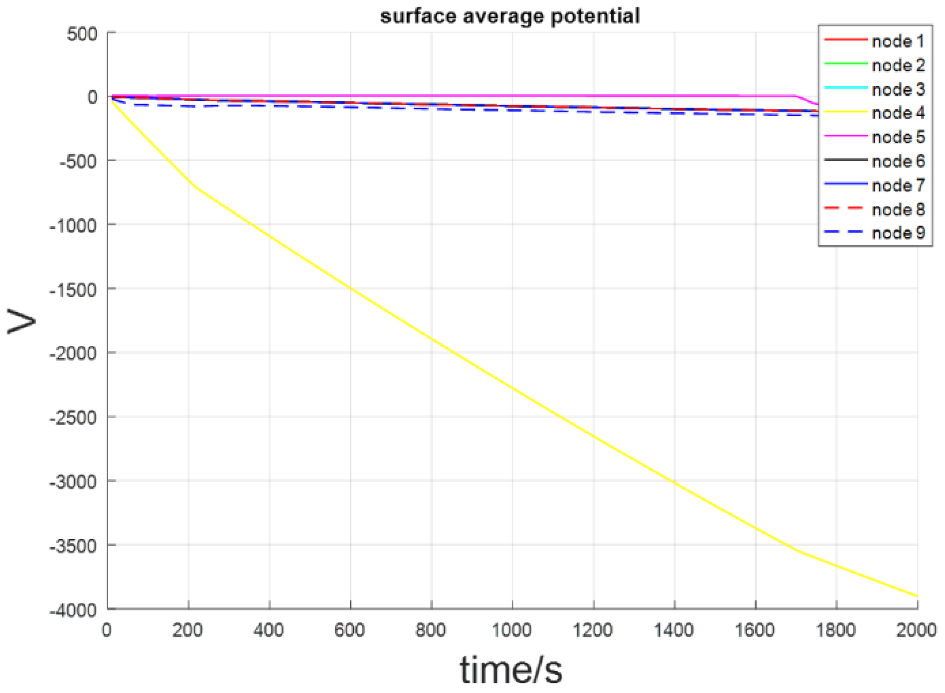
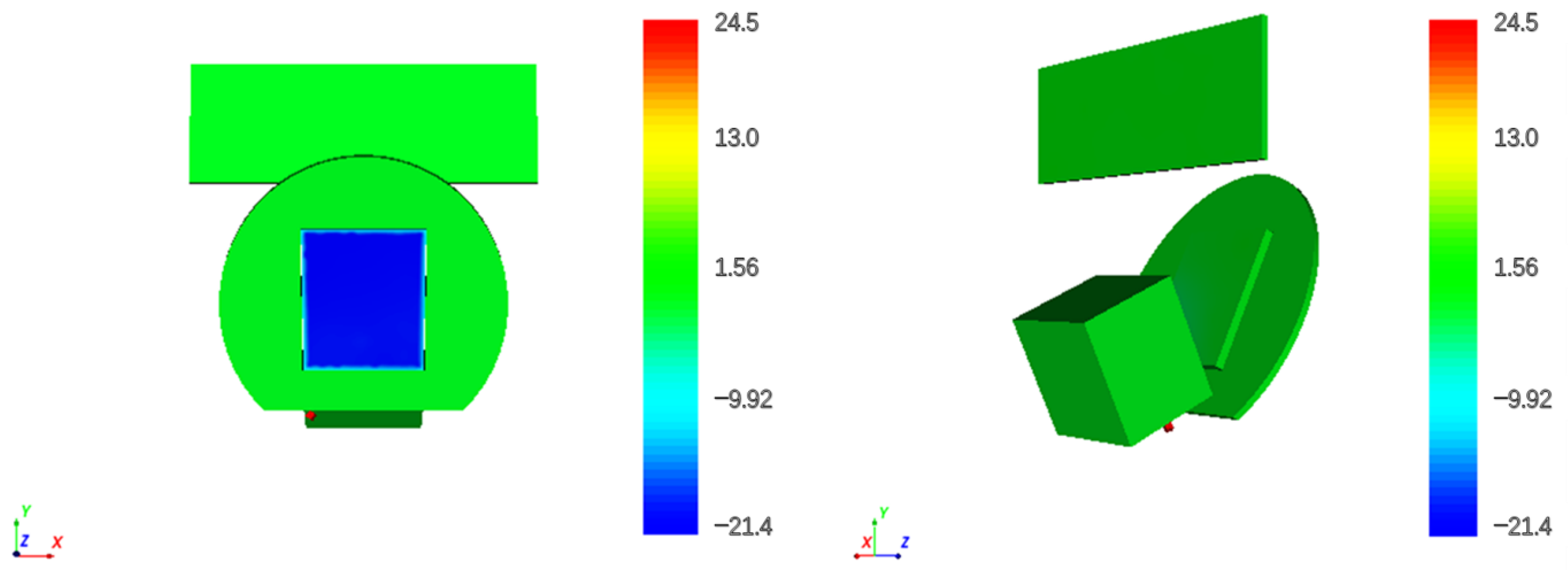
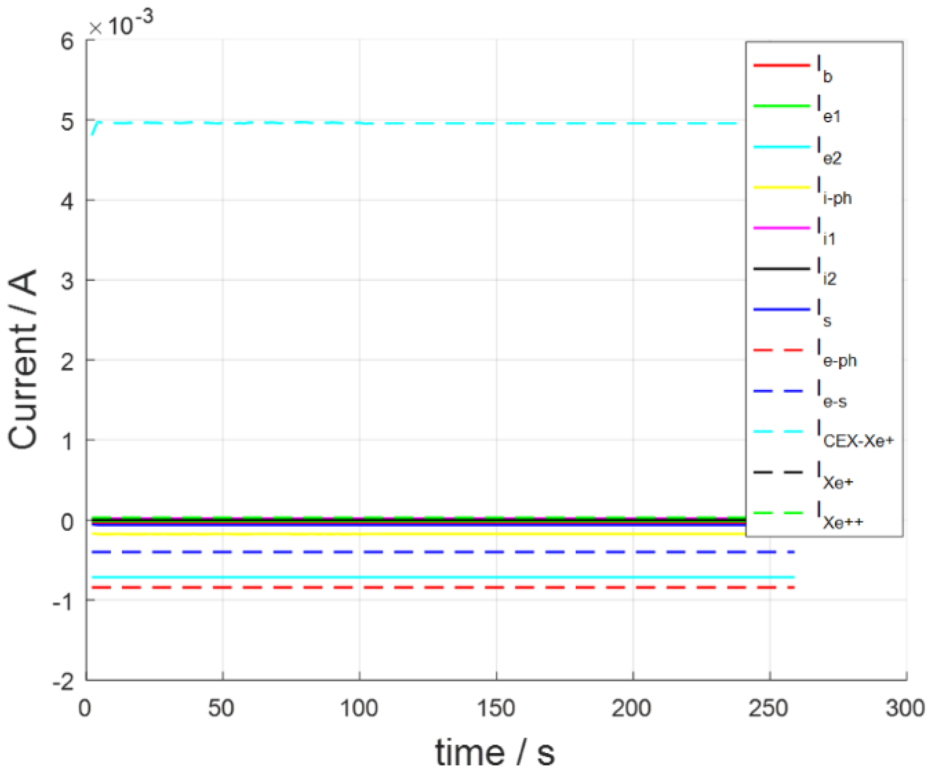
  • With the Hall thruster closed, the glass and other areas are in the vicinity of the existence of a great potential difference, about 3740 V. This region is highly susceptible to electrostatic discharge phenomena, necessitating a certain level of protection to prevent discharges that could impact the performance of nearby payloads.
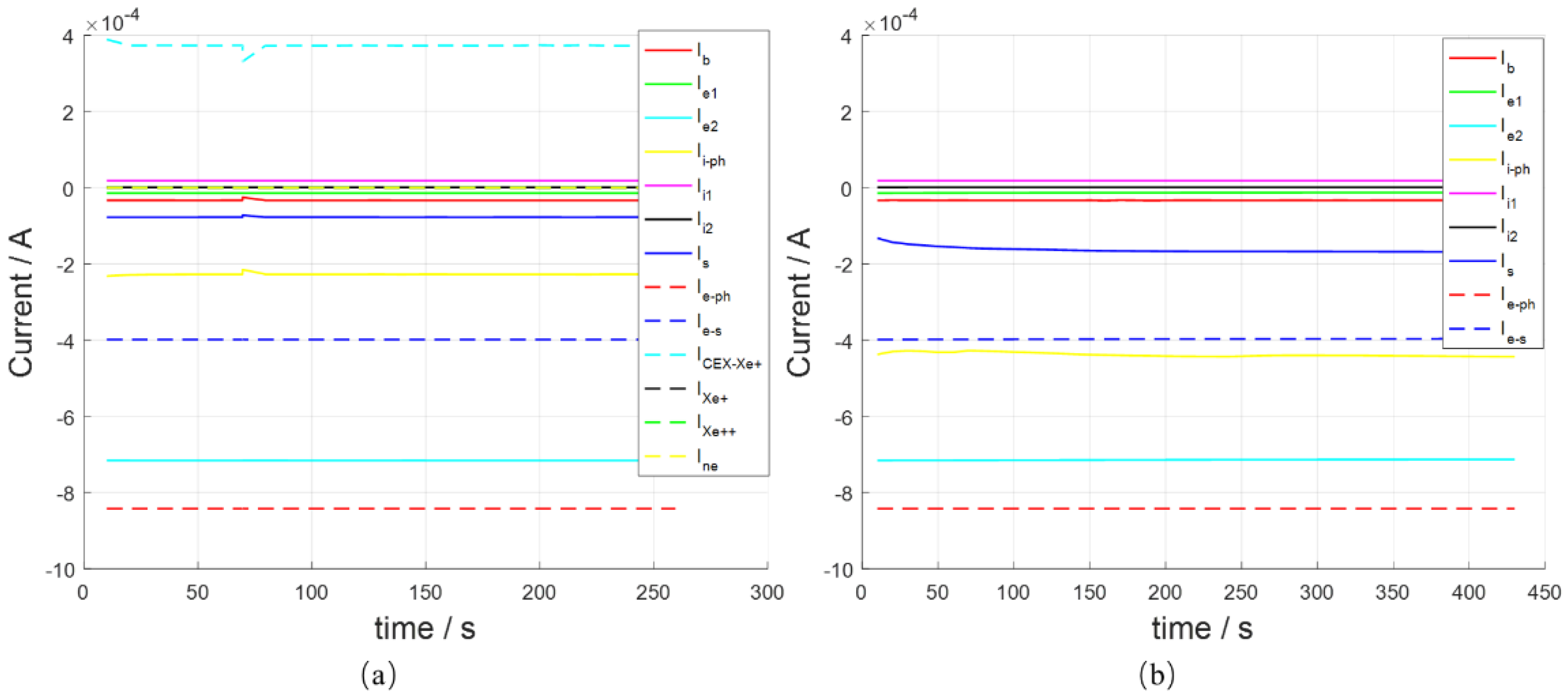
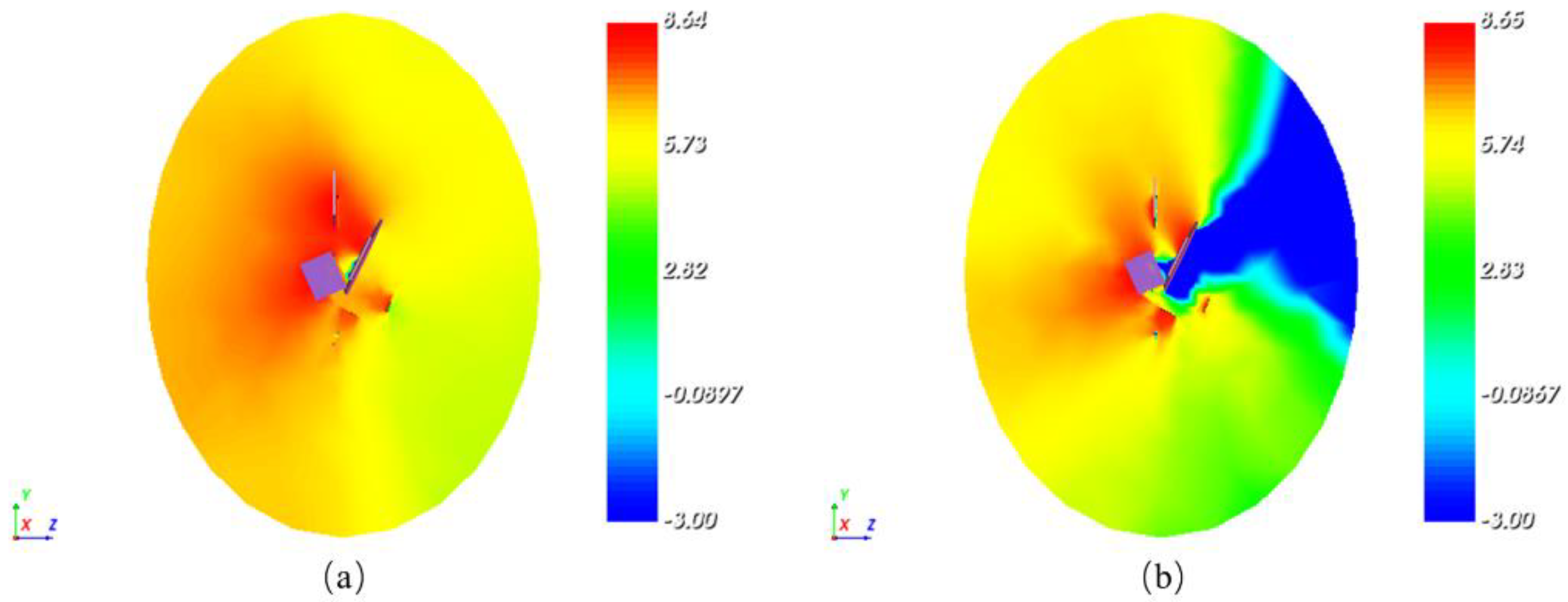
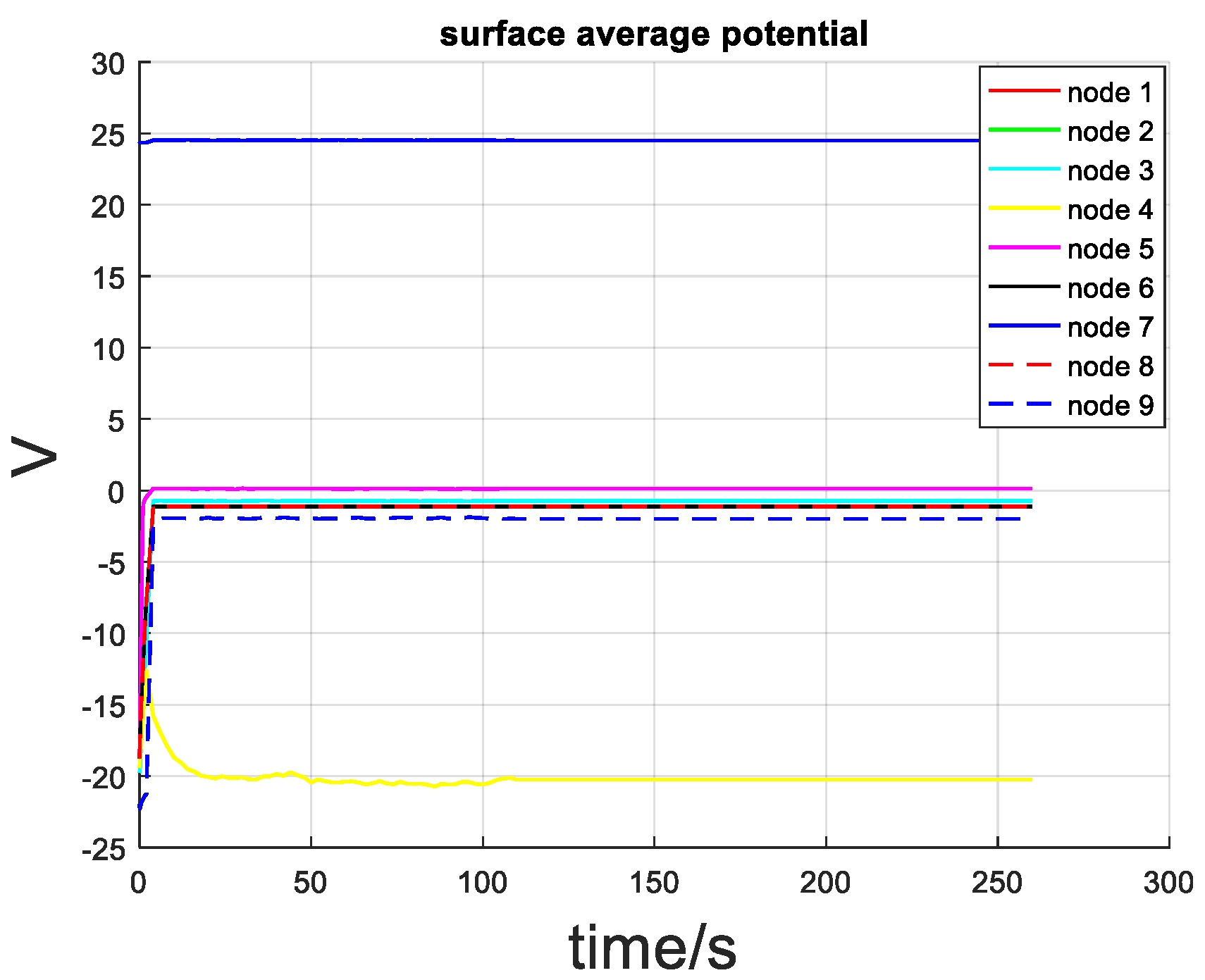
  • The Hall thruster plume has a major effect on the spacecraft surface charging potential, while the influence of the space environment has less of an effect on the surface potential, which is mainly affected by the charge exchange ions in the plume.
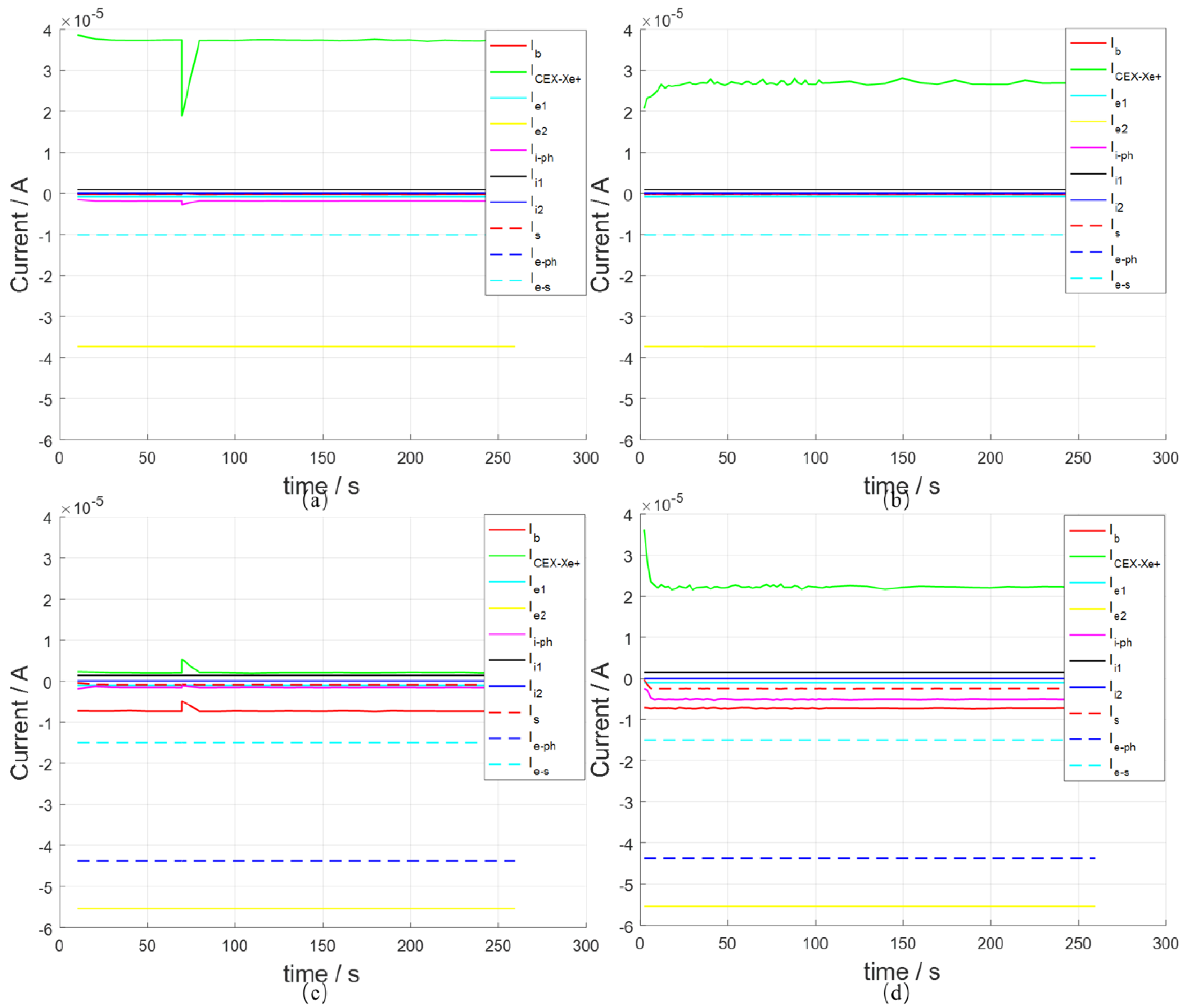
  • The position of the thrusters has almost no effect on the overall surface charging of the satellite, and the surface charging potential of Position 2, where the thrusters are located closer to the main body of the spacecraft, is only 1.3 V higher than the surface charging potential of Position 1. However, when the thruster is in Position 2, more CEX_Xe+ is attracted to the spacecraft surface, which results in a greater deposition contamination of the spacecraft surface.
  • The spacecraft surface potential appears to be the maximum value of the glass surface; by their own shade, not light and poor conductivity of the material, the emission of photoelectrons is inhibited so that the surface potential of the charge moves to a higher position.
The results of this study not only help to deepen the understanding of the possible environmental impacts of Hall thrusters in practical applications, but also provide guidance for the design and selection of spacecraft suitable for specific missions. Through the detailed study of Hall thruster plumes, we can better understand the complex interaction between Hall thrusters and spacecraft, and thus provide a more reliable foundation for the successful execution of future space exploration missions. However, it is important to note that certain factors, such as the intensity of the plume, have not been thoroughly analyzed and investigated, so these conclusions still require further consideration and validation.

Author Contributions

Conceptualization, X.Z. and W.W.; methodology, X.Z. and W.W.; software, C.B.; validation, Z.Y., S.J., Q.C., L.Z. (Lichang Zhang) and L.Z. (Liguo Zhang); formal analysis, X.Z. and W.W.; investigation, Z.Y., S.J., Q.C., L.Z. (Lichang Zhang) and L.Z. (Liguo Zhang); resources, C.B.; data curation, W.W.; writing—original draft preparation, X.Z. and W.W.; writing—review and editing, Z.Z.; visualization, Z.W., S.J. and S.Z.; supervision, Y.S.; project administration, X.Z. and Y.S.; funding acquisition, C.B. All authors have read and agreed to the published version of the manuscript.

Funding

This research was funded by Convolutional Neural Network-based Algorithmic Recognition Algorithm for Particle Waveform Signals on Starboard FPGA Platforms, grant number 42204180.

Institutional Review Board Statement

Not applicable.

Informed Consent Statement

Not applicable.

Data Availability Statement

The original contributions presented in the study are included in the article, further inquiries can be directed to the corresponding author.

Acknowledgments

The authors would like to thank National Space Science Center, Chinese Academy of Sciences, University of Chinese Academy of Science; Shanghai Institute of Satellite Engineering and Shanghai Academy of Spaceflight Technology for their collaborative work in contributing to this study.

Conflicts of Interest

The authors declare no conflicts of interest.

References

  1. Tirila, V.G.; Demairé, A.; Ryan, C.N. Review of alternative propellants in Hall thrusters. Acta Astronaut. 2023, 212, 284–306. [Google Scholar] [CrossRef]
  2. Hang, G.; Li, S.; Kang, X.; Jin, Y.; Sun, W. Current Space Application Status and Future Prospect of Hall Electric Propulsion. J. Propuls. Technol. 2023, 6, 38–51. [Google Scholar] [CrossRef]
  3. Bapat, A.; Salunkhe, P.B.; Patil, A.V. Hall-effect thrusters for deep-space missions: A review. IEEE Trans. Plasma Sci. 2022, 50, 189–202. [Google Scholar] [CrossRef]
  4. Koons, H.C.; Mazur, J.E.; Selesnick, R.S.; Blake, J.B.; Fennell, J.F.; Roeder, J.L.; Anderson, P.C. The impact of the space environment on space systems. NASA STI/Recon Tech. Rep. N 1999, 69036–69041. [Google Scholar]
  5. Gupta, S.B.; Kalaria, K.R.; Vaghela, N.P.; Mukherjee, S.; Joshi, R.S.; Puthanveettil, S.E.; Shankaran, M.; Ekkundi, R.S. An overview of spacecraft charging research in India: Spacecraft plasma interaction experiments—SPIX-II. IEEE Trans. Plasma Sci. 2014, 42, 1072–1077. [Google Scholar] [CrossRef]
  6. Feng, N.; Li, D.; Yang, S.; Chen, Y.; Zhao, C.; Tang, D. Theory Study of Ion Thruster Plume to Spacecraft Surface Charging. High-Volt. Technol. 2016, 5, 1449–1454. [Google Scholar] [CrossRef]
  7. Garrett, H.B. The charging of spacecraft surfaces. Rev. Geophys. 1981, 19, 577–616. [Google Scholar] [CrossRef]
  8. Lieberman, M.A.; Lichtenberg, A.J. Principles of plasma discharges and materials processing. MRS Bull. 1994, 30, 899–901. [Google Scholar]
  9. Allen, J.E.; Annaratone, B.M.; de Angelis, U. On the orbital motion limited theory for a small body at floating potential in a Maxwellian plasma. J. Plasma Phys. 2000, 63, 299–309. [Google Scholar] [CrossRef]
  10. Sjogren, A.; Eriksson, A.I.; Cully, C.M. Simulation of potential measurements around a photoemitting spacecraft in a flowing plasma. IEEE Trans. Plasma Sci. 2012, 40, 1257–1261. [Google Scholar] [CrossRef]
  11. Filleul, F.; Sutherland, O.; Cipriani, F.; Charles, C. BepiColombo: A Platform for Improving Modeling of Electric Propulsion-Spacecraft Interactions. Front. Space Technol. 2021, 2, 639819. [Google Scholar] [CrossRef]
  12. Zheng, Y.; Zhang, Q.; Xiang, H.; Yao, S.; Zheng, Y.; Quan, L. Surface charging and dose monitor on geosynchronous orbit satellite. Open Astron. 2023, 32, 20220211. [Google Scholar] [CrossRef]
  13. Cho, M.; Sumida, T.; Masui, H.; Toyoda, K.; Kim, J.H.; Hatta, S.; Wong, F.K.; Hoang, B. Spacecraft charging analysis of large GEO satellites using MUSCAT. IEEE Trans. Plasma Sci. 2012, 40, 1248–1256. [Google Scholar] [CrossRef]
  14. Zhao, C.; Li, D.; Yang, S.; Qin, X.; Wang, J.; Chen, Y.; Tang, D.; Shi, L. Simulation of Surface Charging of Geosynchronous Orbit Spacecraft. Chin. J. Vac. Sci. Technol. 2014, 12, 1279–1284. [Google Scholar] [CrossRef]
  15. Secretariat, E.C.S.S. Space Environment. ECSS-E-10-04A 2008, ESA Publications Division [Internet]. 2000. Available online: www.spacewx.com/Docs/ECSS-EST-10-04C_15Nov2008.pdf (accessed on 29 January 2016).
  16. Xu, L.; Cai, M.; Yang, T.; Han, J. Surface charging effect of the satellite SMILE. ActaPhysica Sin. 2020, 16, 199–206. [Google Scholar] [CrossRef]
Figure 1. Diagram of spacecraft surface current.
Applsci 14 02650 g001
Figure 2. Spacecraft geometric model diagram.
Applsci 14 02650 g002
Figure 3. The surface potential distribution of the spacecraft when the thruster is turned on.
Applsci 14 02650 g003
Figure 4. The charging process of the average surface potential at various nodes when the thruster is turned on.
Applsci 14 02650 g004
Figure 5. The spacecraft surface potential distribution when the thruster is turned off.
Applsci 14 02650 g005
Figure 6. The charging process of the average surface potential at various nodes when the thruster is turned off.
Applsci 14 02650 g006
Figure 7. Variation of total particle surface currents on the spacecraft under different thruster conditions: (a) thruster is turned on; (b) thruster is turned off.
Applsci 14 02650 g007
Figure 8. Density distribution of photoelectrons under two operating conditions: (a) thruster is turned on; (b) thruster is turned off.
Applsci 14 02650 g008
Figure 9. Surface potential distribution when the thruster is at Position 2.
Applsci 14 02650 g009
Figure 10. The charging process of the average surface potential at various nodes when the thruster is at Position 2.
Applsci 14 02650 g010
Figure 11. Variation of total surface particle currents on the spacecraft when the thruster is at Position 2.
Applsci 14 02650 g011
Figure 12. Variations in spacecraft surface currents over time at Nodes 4 and 9 with the thruster in two positions: (a) Thruster at Position 1, Node 4 current. (b) Thruster at Position 2, Node 4 current. (c) Thruster at Position 1, Node 9 current. (d) Thruster at Position 2, Node 9 current.
Applsci 14 02650 g012
Table 1. Circuit Nodes, Surface Materials, and Equivalent Circuit Parameter Settings.
Spacecraft ComponentsNodesSurface MaterialsConnected NodesEquivalent Circuit
main body (bottom)0Al
thruster (exit)1Al70 Ω
antenna (Z)2Al01 Ω
antenna (-Z)3Carbon fiber05000 Ω
glass (Z)4SiO2050 Ω
solar panel5Solar cell60.3 × 108 Ω
2.85 × 10⁻⁶ F
solar panel6Carbon fiber00 V
thruster7Al10 Ω
main body8Al05 Ω
glass (-Z)9SiO205000 Ω
Table 2. GEO extreme plasma environment parameters.
Density/(cm−3)Temperature/(keV)
elec10.20.4
elec21.227.5
ion10.60.2
ion21.328
Table 3. Collection of photoelectron current and Xe+ current.
Location of the ThrusterCollection of Photoelectron Current (A)Collection of Xe+ Current (A)
Node 411.8 × 10−63.75 × 10−5
202.75 × 10⁻⁵
Node 9102 × 10−6
25 × 10−62.25 × 10−5
Disclaimer/Publisher’s Note: The statements, opinions and data contained in all publications are solely those of the individual author(s) and contributor(s) and not of MDPI and/or the editor(s). MDPI and/or the editor(s) disclaim responsibility for any injury to people or property resulting from any ideas, methods, instructions or products referred to in the content.

