Article

Insertion Performance Study of an Inductive Weft Insertion System for Wide Weaving Machines

1
School of Mechanical Engineering and Automation, Wuhan Textile University, Wuhan 430200, China
2
Hubei Digital Textile Equipment Key Laboratory, Wuhan Textile University, Wuhan 430200, China
3
Hubei Provincial Engineering Research Center of Industrial Detonator Intelligent Assembly, Wuhan 430200, China
*
Author to whom correspondence should be addressed.
Appl. Sci. 2024, 14(7), 2687; https://doi.org/10.3390/app14072687
Submission received: 13 February 2024 / Revised: 16 March 2024 / Accepted: 20 March 2024 / Published: 22 March 2024

Abstract

:
Wide weaving machines traditionally enhance the weaving width by increasing the shuttle’s initial velocity. However, this approach introduces challenges like pronounced equipment vibration, elevated noise levels, heightened energy consumption, and a reduced lifespan. Moreover, its efficacy in significantly widening fabric is constrained. Addressing these concerns, this paper proposes a wide-width warp insertion solution that involves driving the high-temperature superconducting shuttle to achieve high-speed horizontal flight through a traveling magnetic field. The inductive weft insertion system structure of wide weaving machines comprises an insertion guideway with an iron core and wound electromagnetic coils. The shuttle consists of a high-temperature superconducting block and a conductive plate, serving as the driving element. By establishing the equivalent circuit of the weft insertion guideway and the suspended shuttle, the calculation formula for the dynamic driving performance of the weft insertion guideway is obtained. Utilizing a transient 3D magnetic field simulation model, the impact of parameters like the current frequency, shuttle conductive plate thickness, and suspension gap on weft insertion performance is explored. Successful wide-width weft insertion motion is achieved by controlling coil input current parameters. Finally, an experimental platform is constructed to validate the correctness of the weft insertion system structure and simulation model through practical experiments.

1. Introduction

Weaving machines are crucial pieces of mechanical equipment in textile production, and the fabrics they produce find extensive applications in various fields such as clothing, home textiles, aerospace [1], military defense, rail transportation, marine vessels, hydraulic construction, environmental protection, and more [2]. In particular, lightweight and wide carbon fiber fabrics exhibit characteristics such as a high strength, a high modulus, corrosion resistance, fatigue resistance, and seamless construction [3]. When used over large areas, they possess greater overall strength and stability [4]. Currently, the usual approach to enhance the initial velocity of the shuttle, thus increasing the weaving speed and width of the loom, involves improving the mechanical shuttle-throwing structure or employing electromagnetic launching methods. The Swiss company Sulzer improved the shuttle-throwing structure by replacing the fixed cam with a rotating cam, optimizing the cam’s motion curve. This modification reduces the friction between the cam and the shuttle-throwing lever, resulting in a 1.7% increase in the mechanical efficiency of the shuttle-throwing machine [5]. Mirjalilil [6] studied the electromagnetic driving force of the weaving machine’s electromagnetic emission coil. Owlia [7,8,9], from Yazd University, Iran, further utilized the electromagnetic emission coil to accelerate the ferromagnetic pellets that draw the warp threads. Through experimental research on the projectile ejection speed under different parameters of the electromagnetic coil, they established an adaptive neural network model that accurately predicts the projectile speed. Xu [4,10] designed a multi-stage electromagnetic emission structure to increase the initial speed of the warp inserter and concluded that a warp inserter initial speed as high as 126 m/s is required to achieve a 12 m wide fabric. Compared to the mechanical shuttle insertion method, electromagnetic warp insertion provides a faster initial speed for warp insertion, allowing the yarn to travel a greater distance in the shuttle space. However, accelerating the warp inserter to extremely high speeds in a short period results in excessive acceleration for both the inserter itself and the tensioned yarn, leading to severe fluctuations in yarn tension and causing warp thread breakage issues [11,12]. Taking cotton yarn with a strength of 15 cN/tex and a linear density of 200 tex as an exampled, its maximum tensile strength is 30 N, which cannot meet the requirements of high-acceleration wide-width weft insertion. This is particularly problematic in the production of lightweight and wide-width fabrics, as the high acceleration of ultra-fine yarns increases the risk of breakage, limiting the range of wide-width fabrics that can be produced using this method. In summary, whether through improving the shuttle mechanism or changing the warping method, both approaches have limitations in increasing fabric width, and they impose high demands on mechanical structures and yarn strength. Therefore, this paper proposes a high-temperature superconducting magnetic levitation inductive electromagnetic warping scheme. This scheme utilizes the traveling magnetic field generated when the coil winding is energized with an AC to guide the shuttle during the warping process. The levitation force of the shuttle during warping is provided by the high-temperature superconductor. Compared to existing wide-width warping methods, this scheme possesses the following characteristics:
(1)
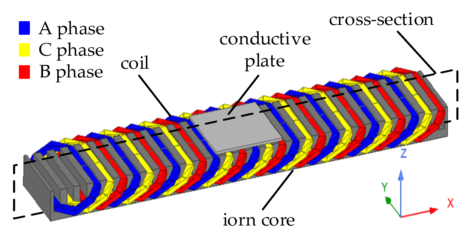
Using the electromagnetic traction wound around the iron core as the force to pull the shuttle, achieving a super-wide weft insertion can be realized by increasing the length of the coil and the iron core, no longer restricted by the initial velocity of the shuttle. Moreover, since the installation position of the weft insertion guideway is below the warp threads, it is not limited by the size of the shuttle opening, making the design of the weft insertion guideway more flexible and convenient to install.
(2)
Utilizing the levitation force generated by high-temperature superconductors in the magnetic field of the permanent magnet array to support the suspended shuttle, there is no actual contact between the shuttle and the weft insertion guideway and warp threads. This eliminates issues such as wear, heating, noise, and vibration caused by friction during the weft insertion process, contributing to an extended equipment lifespan.
In this paper, a novel structure for the weft insertion guideway was designed. Based on the technical specifications of the weft insertion process of the loom, various structural parameters of the weft insertion guideway were calculated. On this basis, a mathematical model and a simulation model of the weft insertion guideway-shuttle-weft yarn were established. These efforts sought to provide valuable insights for the design and manufacturing of high-performance wide-width looms.

2. Weft Insertion System Structure and Operating Principles

The weft insertion system can be divided into three parts: a weft insertion guideway, a permanent magnet array, and a magnetic levitation shuttle (hereinafter referred to as the shuttle). The three-dimensional structure is illustrated in Figure 1a. The weft insertion guideway is installed below the lower warp, with two permanent magnet arrays mounted on either side of it. The shuttle is suspended above the weft insertion guideway and permanent magnet arrays, positioned at an angle between the upper and lower warps. The weft insertion guideway consists of an iron core made from stacked silicon steel sheets and electromagnetic traction coils. The electromagnetic traction coils are wound in a short-distance double-layer stacking (i.e., “half-filled slot”) fashion on the teeth of the iron core, forming three groups of windings. In the winding connection scheme shown in Figure 1b, S represents the number of slots on the iron core of the weft insertion guideway. Each coil of the winding spans two iron core slots, with the center of two adjacent magnetic poles spanning three iron core slots. The slot–tooth pitch is 60° in the electrical angle. Figure 1c depicts the schematic structure of the shuttle shown in Figure 1a. The shuttle consists of a conductive plate, high-temperature superconductor, and a fixed plate. The conductive plate is embedded beneath the shuttle, with its lower surface parallel to the lower surface of the fixed plate. At the tail of the shuttle, there is a selvedge device designed to clamp and guide the weft yarn during insertion. Inside the shuttle, there are cavities on each side of the conductive plate, intended for securing the high-temperature superconductor and containing liquid nitrogen.
When a suitable symmetrical three-phase alternating current is applied to the electromagnetic coil windings, a traveling magnetic field is generated in the gap between the warp insertion guideway and the suspended shuttle. This results in the induction of eddy currents in the shuttle’s conductive plate. The interaction between the eddy current magnetic field and the source magnetic field of the warp insertion guideway generates traction force, thereby driving the shuttle to pull the weft yarn and achieve weft insertion.
Simultaneously, after the superconducting material inside the shuttle’s two cavities is cooled with liquid nitrogen, the change in the magnetic field induces a superconducting current within the material. Consequently, a magnetic field opposite to the external magnetic field is generated inside the superconductor, aiming to counteract the influence of the external magnetic field. Two opposing magnetic fields enable the superconductor to stably levitate above the permanent magnet arrays on both sides of the weft insertion guideway, providing levitation force equal to the weight of the shuttle and sufficient guiding force to maintain shuttle stability.
By appropriately designing the structural dimensions of the conductive plate and changing the frequency of the input current, stable and rapid weft insertion motion can be maintained under continuously changing yarn tension and suspension height.

3. Calculation of Weft Insertion Performance Parameters

3.1. Equivalent Circuit of the Weft Insertion System

The driving part of the weft insertion system consists of the guideway and the conductive plate, with the permanent magnet array installed on both sides of the guideway. The impact of the permanent magnet array on the weft insertion system’s performance can be neglected. Therefore, when studying the weft insertion system’s performance, it is sufficient to focus on the guideway and the conductive plate and establish an equivalent circuit. The electromagnetic traction coils are wound around the core of the weft insertion guideway in a “half-filled slot” manner, and there is an end effect at both ends of the core. In situations where the thickness of the conductive plate and the air gap are relatively large, the impact of the leakage reactance and skin effect of the conductive plate cannot be ignored. Let K r ( s ) and K x ( s ) be correction factors for the resistance and magnetizing reactance of the conductive plate due to the longitudinal dynamic end effect, and let C r ( s ) and C x ( s ) be correction factors for the resistance and magnetizing reactance of the conductive plate due to the transverse end effect, respectively. K f is the correction factor for the resistance of the conductive plate due to the skin effect. The equivalent circuit of the weft insertion guideway and the conductive plate can be represented as shown in Figure 2.
In this figure, r 1 is the resistance of the electromagnetic traction coil, x 1 is the leakage reactance of the electromagnetic traction coil, x m 0 is the magnetizing reactance, r 2 is the resistance of the conductive plate referred to the electromagnetic traction coil, and x 2 is the leakage reactance of the conductive plate.
In one-dimensional field analysis [13], we can separate the longitudinal and transverse end effects and then superimpose the separately processed results to obtain the analytical result that includes the total end effects. At the same time, according to the relationship of equal complex power in the field circuit, we can obtain the equations for K r ( s ) , K x ( s ) , C r ( s ) , and C x ( s ) . These are all equations about the slip ratio, and when the slip ratio is very small, C r ( s ) and C x ( s ) can be written separately as
C r ( s ) = s G { Re 2 [ T ] + Im 2 [ T ] } Re [ T ]
C x ( s ) = { Re 2 [ T ] + Im 2 [ T ] } Im [ T ]
In the above equation,
T = j [ r 2 + ( 1 r ) λ α a tanh α a ]
r 2 = 1 1 + j s G
λ = 1 1 + 1 r tanh α a tanh k ( c a )
where G is the quality factor, 2 a is the width of the weft insertion guideway core, 2c is the transverse length of the conductive plate, α = c τ , k = π τ , and τ is the polar distance of the weft insertion guideway.
In the process of warp insertion, the angle between the upper warp and the lower warp is small, and the space available for installing the warp insertion guideway is limited. Therefore, the gap thickness of the designed guideway and the thickness of the conductive plate in this paper are relatively small. Considering the uniformity of the conductive plate [14], the influence of secondary leakage inductance and the skin effect of the secondary conductor on the electromagnetic warp-insertion guideway characteristics can be neglected. Moreover, during the warp-insertion motion, the shuttle primarily operates in the central portion of the warp-insertion guideway. At this point, the influence of end effects can also be neglected, i.e., setting K r = K x = C x = K f = 1 and x 2 = 0 . The equivalent circuit depicted in Figure 2 can be simplified to the approximate equivalent circuit shown in Figure 3.
The reactive power equality relationship gives the magnetizing reactance as in Equation (6):
x m 0 = 4 m 1 μ 0 ( W 1 k w 1 ) 2 a V s π k δ k μ δ p e
where m 1 is the number of phases in the power source, μ 0 is the vacuum permeability, W 1 is the number of turns per phase connected in series in the weft insertion guideway winding, k w 1 is the winding factor, k δ and k μ are the gap factor and saturation factor of the weft insertion guideway, δ is the gap thickness between the weft insertion guideway and the conducting plate, and p e is the equivalent number of pole pairs.
Based on the principle of equal complex power in the field path and Weber’s law, the equivalent resistance of the conductor plate assigned to the weft insertion guideway is obtained as follows:
r 2 = 4 m 1 ρ 2 ( W 1 k w 1 ) 2 2 p e 2 a τ d
where ρ 2 is the volume conductivity of the conductor plate and d is the thickness of the conductor plate.
The starting internal power factor refers to the internal power factor of the weft insertion system during the startup process, reflecting the power factor condition of the internal components of the weft insertion system. Its expression is as follows:
cos θ i = 1 1 + ( C r r 2 s x m 0 ) 2
The primary per-phase resistance is given by Equation (9):
r 1 = ρ 1 2 L c p W 1 A
where ρ 1 is the resistivity of the guideway coil winding, L c p is the average half-turn length of the winding, and A is the cross-sectional area of the winding.
The per-phase leakage inductance of the guideway coil winding is given by Equation (10):
x 1 = 15.8 f 100 ( W 1 100 ) 2 2 a q 1 ( λ s p + λ t + λ e + λ d p e )
where f is the power supply frequency, q 1 is the number of slots per phase per pole of the guideway, p is the pole pair number, and λ s , λ t , λ e ,   and   λ d are the leakage magnetic conductances for the slot, tooth end, winding end, and harmonic, respectively.
Letting k μ = 1 , by combining Equations (6)–(8), we can derive the formula for calculating the thickness of the conductive plate as given in Equation (11):
δ d 2 f τ 2 s μ 0 1 cos 2 θ i π C r ρ 2 k δ cos θ i
Also, since the synchronous speed of the warp insertion guideway is V S = 2 f τ , the above equation can be expressed as a linear equation in terms of δ as
d = π C r ρ 2 cos θ i V S τ s μ 0 1 cos 2 θ i k δ δ
The above equation indicates that, in the case where other parameters of the weft insertion system have been determined, the thickness can be expressed as having a proportional relationship with the air gap. In order to obtain the maximum traction force, the thickness of the conductive plate is determined only by the gap thickness between the warp insertion guideway and the shuttle. Moreover, the selection of the conductive plate thickness should monotonically increase with the increase in gap thickness.

3.2. The Calculation of Warp Insertion Performance

Based on the aforementioned approximate equivalent circuit of the warp insertion guideway and the corresponding parameter calculation formulas, the performance calculation of the warp insertion guideway can be completed. Let U 1 be the input phase voltage of the warp insertion guideway winding, and let m 1 be the number of phases in the power supply.
The expression for the winding phase current, neglecting the asymmetry between phases, can be represented as
I 1 ( s ) = U 1 s C r r 2 j 1 x m 0 1 + ( s C r r 2 j 1 x m 0 ) ( r 1 + j x 1 ) ( A )
Therefore, the power factor of the warp insertion guideway can be expressed as
cos φ = cos ( arg I 1 ( 1.0 ) )
Unlike cos θ i , cos φ represents the power factor of the entire weft insertion system, indicating the power factor level of the weft insertion system during startup.
The magnitude of the traction force of the warp insertion guideway is given by
F ( s ) = m 1 C r r 2 V s s U 1 2 [ 1 + ( s C r r 2 j 1 x m 0 ) ( r 1 + j x 1 ) ] ( N )
The startup input power is given by
P 1 = m 1 U 1 I 1 ( 1.0 ) cos φ
The startup synchronous power is given by
P δ = F V s
Assuming that during the warp insertion process, the shuttle moves only along the warp insertion guideway, while neglecting mechanical losses, the startup synchronous efficiency of the warp insertion system is given by
η c = P δ P 1

4. Results Analysis and Validation

4.1. Simulation Verification

In the design process of the warp insertion system, the core task is the study of the traction force of the warp insertion guideway. To verify the correctness of the formula for calculating the traction force of the warp insertion guideway, the structural parameters of the warp insertion guideway were calculated based on the formula for the linear motor structure [15]. We established a transient magnetic field 3D simulation model for the warp insertion system, as shown in Figure 4.
In Figure 4, the three-phase coils are wound around the core of the warp insertion system using a short-distance double-layer winding method, and the coil connection is the same as shown in Figure 1. The conductive plate of the shuttle is located above the warp insertion system. The excitation source for the three-phase coils is assumed to be a three-phase voltage source, and the voltage expression is given by Equation (19). The simulation model has the remaining parameters listed in Table 1.
{ V A ( t ) = 180 sin ( 2 π f t ) V b ( t ) = 180 sin ( 2 π f t + 2 π 3 ) V b ( t ) = 180 sin ( 2 π f t + 4 π 3 )
After setting up the simulation parameters, with a simulation duration of 100 ms and a step size of 1 ms, Figure 5 shows the magnetic field contour of the cross-section of the warp insertion guideway and the distribution of the induced magnetic field strength on the conductor plate when the power supply frequency is 50 Hz. From left to right, the subfigures depict the magnetic field characteristics at simulation times of 60 ms, 65 ms, and 70 ms, respectively. In each subfigure, the lower part illustrates the magnetic field generated by the weft insertion guideway, including the magnetic flux distribution, while the upper part displays the distribution of induced magnetic field intensity and direction in the conducting plate. From Figure 5, it can be observed that after applying three-phase voltage, the warp insertion guideway generates a rapidly moving wave magnetic field to the right, inducing an eddy current magnetic field in the conductor plate. Under the interaction of these two magnetic fields, the warp insertion guideway generates a continuous traction force on the shuttle, causing the shuttle to move to the right and achieve warp insertion. By using a variable frequency drive to provide three-phase voltage with the opposite phase sequence, the direction of the traction force can be changed.
To further investigate the impact of various parameters on the traction force of the drafting guideway, simulations were conducted to separately analyze the variation in the traction force with parameters such as the thickness of the conductive plate, drafting guideway slip rate, and power frequency. Subsequently, the simulation results of the latter two parameters were compared and analyzed with the theoretical values calculated.
Figure 6 shows the variation curve of the traction force as a function of the thickness of the conductive plate when the slip rate is 1 (shuttle at rest) and the power frequency is 50 Hz. In Figure 6, it can be observed that at gap thicknesses of 6 mm, 8 mm, and 10 mm, the traction force reaches its maximum when the thickness of the conductive plate is 3 mm, 4 mm, and 5 mm, respectively. This is roughly consistent with the relationship between the conductive plate and gap thickness in Equation (12), with an error of 2.67%. To ensure that the shuttle is not affected by the warp during the drawing-in process and to leave a margin in the suspension height, the initial suspension height of the shuttle should be around 10 mm. Therefore, when using the conductive plate as the driving force for the shuttle, in order to obtain greater starting traction force and reduce the starting distance, the optimal thickness of the conductive plate is 5 mm.
Figure 7 shows the curves of the traction force and efficiency of the weft insertion guideway with respect to the slip rate when the air gap thickness is 10 mm, the power frequency is 50 Hz, and the conductive plate thickness is 5 mm. In Figure 7, it can be observed that as the slip rate gradually increases, both the traction force and efficiency show an increasing trend followed by a decrease, reaching their maximum values at a slip rate of 0.3. This is because when the slip rate is less than 0.3, there is a traction force generated in the secondary conductive plate due to the induced eddy current, and it increases with an increase in the slip rate. However, when the slip rate exceeds 0.3, the energy generated by the induced eddy current in the secondary conductive plate is dissipated in the form of heat, leading to a decrease in both the traction force and efficiency.
Figure 8 depicts the curve of the traction force of the weft insertion guideway with respect to the power frequency when the gap thickness is 10 mm, the slip rate is 0.3, and the thickness of the conductive plate is 5 mm. In Figure 8, it can be observed that the traction force increases first and then decreases with the power frequency, reaching its maximum at 60 Hz. This is due to the fact that, with the current magnitude unchanged, higher electrical frequencies result in an increased eddy current and hysteresis losses. Therefore, to ensure sufficient traction force for the shuttle during start-up and weaving, and to reduce energy losses, the rated slip ratio of the warp-insertion system should be around 0.3. This implies that the weaving machine should operate at a high speed, and the optimal power frequency is 60 Hz.

4.2. Experimental Verification

To validate the accuracy of the analytical and simulation calculations, a prototype of the weft insertion guideway was manufactured, and an experimental platform was set up, as shown in Figure 9. The experimental platform consisted of a variable frequency drive, a weft insertion guideway, a shuttle conductive plate, a tension sensor, and a sliding rail. The support force provided by the sliding rail replaced the suspension force of the superconductor, and a tension sensor was used to measure the traction force of the weft insertion guideway. The output voltage of the variable frequency drive used in the experiment is given by Equation (19), with a frequency ranging from 0 to 100 Hz. The structural parameters of the experimental platform are listed in Table 1.
Figure 10 depicts the variation of the traction force exerted by the weft insertion guideway on the conductive plate with the frequency of the power source when the conductive plate thickness is 5 mm, the air gap thickness is 10 mm, and the slip ratio is 1. As seen in Figure 10, the data results for the traction force from the analytical calculations, simulation calculations, and experimental measurements align closely with changes in the power source frequency. This confirms the accuracy of the simulated model for the weft insertion guideway and conductive plate established in this study. These findings hold significant implications for the design of an inductive weft insertion guideway in wide-width looms.

5. Conclusions

In addressing the challenges of wide weaving, this paper proposed a wide-width warp insertion solution, detailing the structure of an inductive weft insertion system for wide weaving machines. The equivalent circuit of the weft insertion guideway and the suspended shuttle was established and simplified, resulting in the derivation of the calculation formula for the mechanical performance of the weft insertion guideway. Finally, feasibility experiments were designed and conducted to validate the proposed wide-width inductive weft insertion structure. The following conclusions are drawn:
(1)
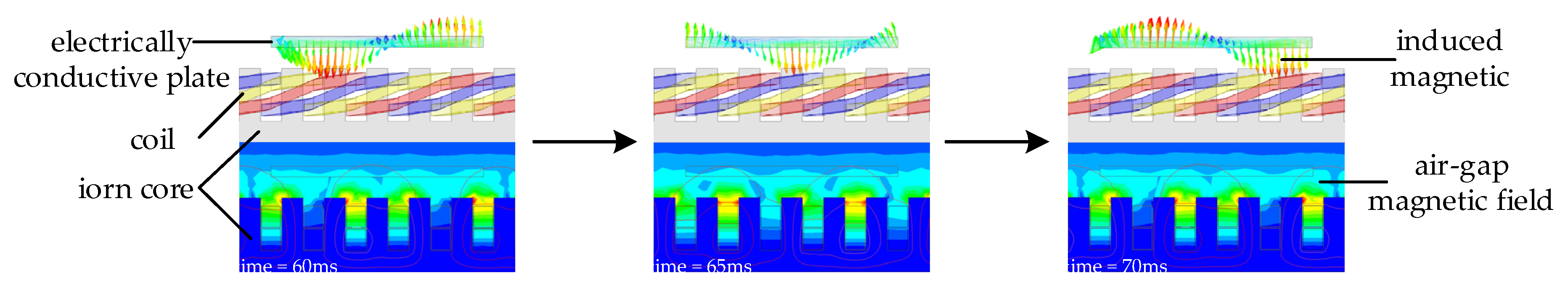
After applying three-phase AC power, the electromagnetic coils continuously generate a rapidly moving unidirectional magnetic field. This field consistently provides stable traction force to the suspended shuttle during the warp insertion process, allowing the weaving machine to achieve a wide warp insertion width without being constrained by the initial velocity of the shuttle.
(2)
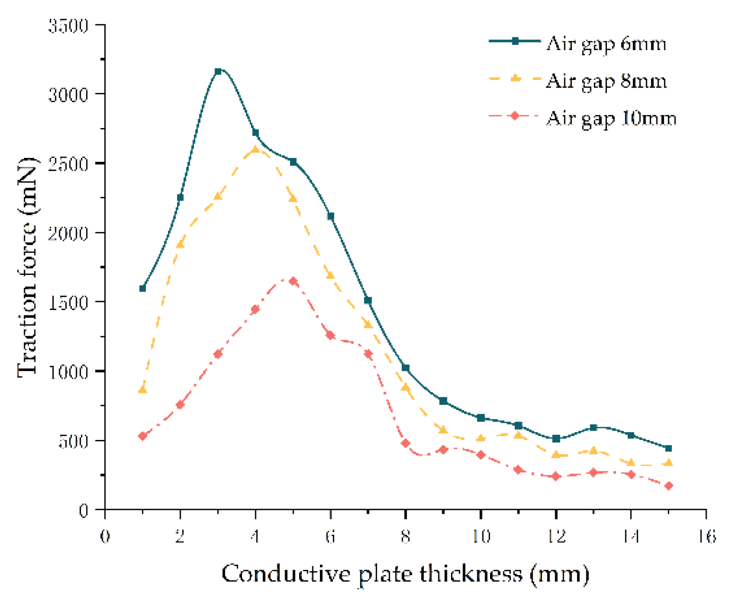
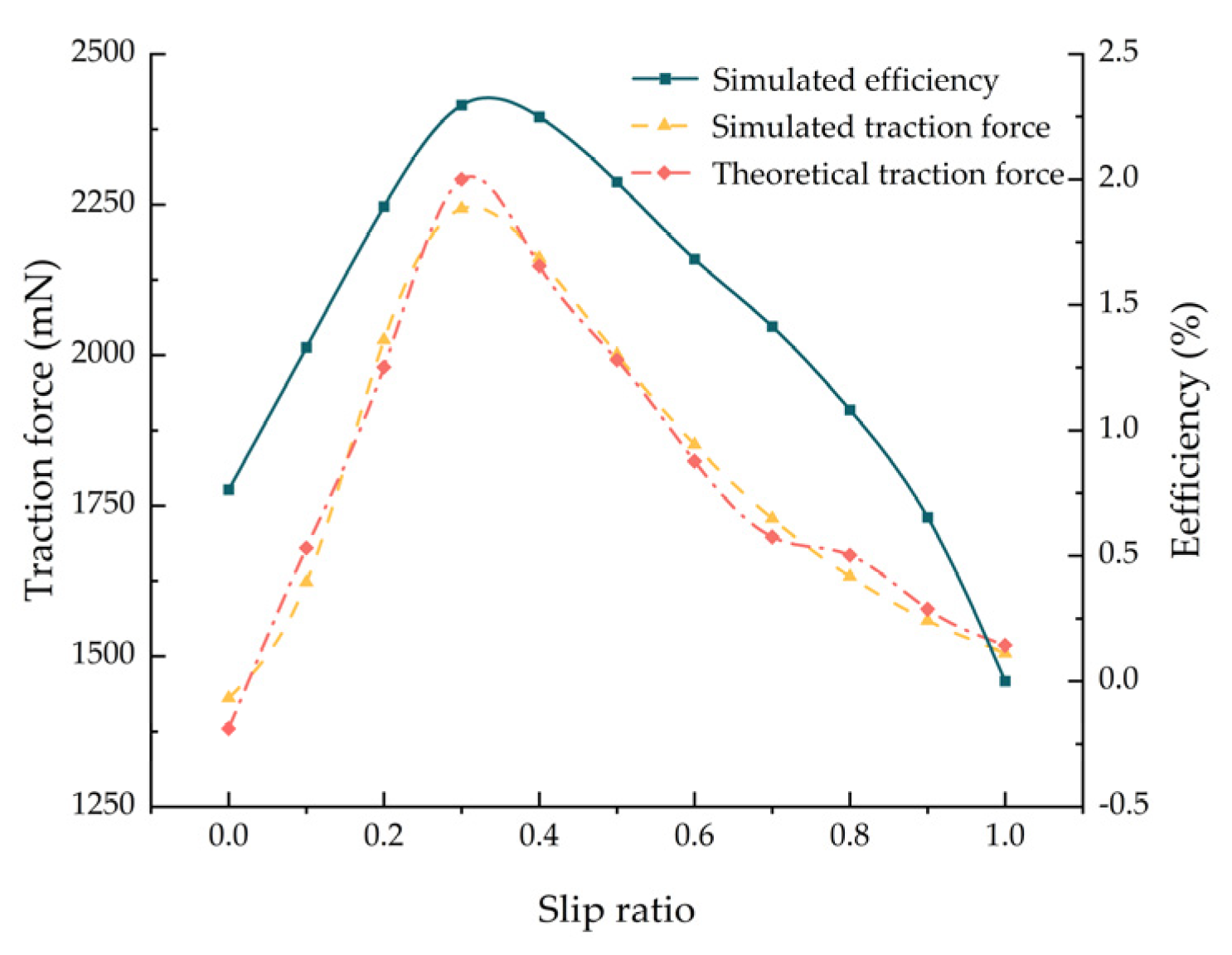
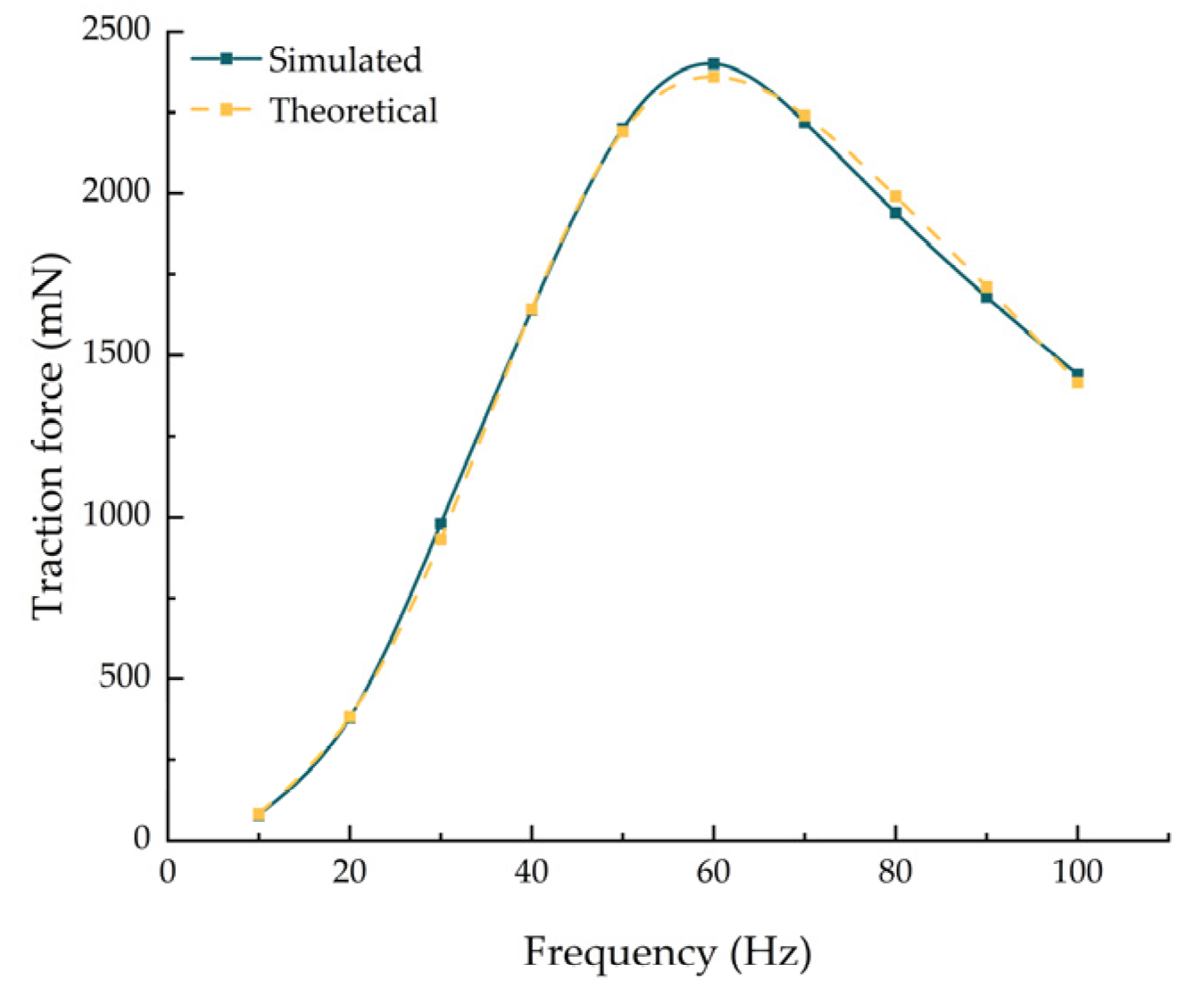
This study investigated the impact of various parameters, including shuttle structure, misalignment ratio, and current frequency, on the performance of the warp insertion guideway. The optimal design parameters for the warp insertion system, aiming to achieve maximum traction force and minimize energy loss, were determined: a shuttle suspension height of 10 mm, a thickness of 5 mm for the shuttle conductive plate, a misalignment ratio of 0.3, and a current frequency of 60 Hz. These findings provide a theoretical foundation for the application of the inductive warp insertion system in wide weaving machines.

Author Contributions

Conceptualization, C.Z. and Y.L.; Data curation, Y.L. and Y.P.; Funding acquisition, C.L. and X.Z. (Xiaoyan Zuo); Methodology, Y.P. and Y.W.; Software, C.L. and X.Z. (Xiaoyan Zuo); Supervision, C.Z. and X.Z. (Xiangyang Zhou); Validation, X.Z. (Xiaoyan Zuo), C.X. and X.Z. (Xiangyang Zhou); Writing—original draft, Y.L. All authors will be informed about each step of manuscript processing including submission, revision, revision reminder, etc. via emails from our system or assigned Assistant Editor. All authors have read and agreed to the published version of the manuscript.

Funding

This project is supported by the National Natural Science Foundation of China (Project No. 51875414), Wuhan Applied Basic Frontier Project (2022013988065209), Wuhan Knowledge Innovation Special Project (2023010201010115).

Institutional Review Board Statement

Not applicable.

Informed Consent Statement

Not applicable.

Data Availability Statement

Data are contained within the article.

Conflicts of Interest

The authors declare no conflicts of interest.

References

  1. Cherston, J.; Veysset, D.; Sun, Y.; Wilbert, J.H.S.; Yano, H.; Nelson, K.A.; Murari, S.; Paradiso, J.A. Large-area electronic skins in space: Vision and preflight characterization for first aerospace piezoelectric e-textile. In Proceedings of the Sensors and Smart Structures Technologies for Civil, Mechanical, and Aerospace Systems 2020, Online, 27 April–8 May 2020; pp. 239–252. [Google Scholar]
  2. Daria, M.; Krzysztof, L.; Jakub, M. Characteristics of biodegradable textiles used in environmental engineering: A comprehensive review. J. Clean. Prod. 2020, 268, 122129. [Google Scholar] [CrossRef]
  3. Liu, Y.; Zwingmann, B.; Schlaich, M. Carbon fiber reinforced polymer for cable structures—A review. Polymers 2015, 7, 2078–2099. [Google Scholar] [CrossRef]
  4. Xu, Q.; Mei, S.; Yan, X.; Islam, M.M.; Chen, Z.; Wang, S.; Zhang, Z. Analysis of the magnetic field and electromagnetic force of a non-striking weft insertion system for super broad-width looms, based on an electromagnetic launcher. Text. Res. J. 2019, 89, 4620–4631. [Google Scholar] [CrossRef]
  5. Markus, G. Gripper Head for the Insertion of Weft Threads on a Gripper Weaving Machine. U.S. Patent 8,875,747(B2), 4 November 2014. [Google Scholar]
  6. Mirjalili, S.A. Using Electromagnetic Force in Weft Insertion of a Loom. Fibres Text. East. Eur. 2005, 13, 67–70. [Google Scholar]
  7. Owlia, E.; Mirjalili, S.A. The effect of launcher parameters on the projectile velocity in laboratory electromagnetic weft insertion system. J. Text. Inst. 2021, 112, 1232–1239. [Google Scholar] [CrossRef]
  8. Owlia, E.; Mirjalili, S.A.; Shahnazari, M. Design and modeling of an electromagnetic launcher for weft insertion system. Text. Res. J. 2019, 89, 834–844. [Google Scholar] [CrossRef]
  9. Owlia, E. Optimization of the projectile velocity in electromagnetic weft insertion system by genetic algorithm. J. Text. Inst. 2023, 114, 364–370. [Google Scholar] [CrossRef]
  10. Xu, Q.; Cui, X.; Mei, S.; He, Y.; Chen, Z.; Meng, F. Structural Performance Optimization Design of Continuously Accelerating Electromagnetic Weft Insertion System. Appl. Sci.—Basel 2022, 12, 3611. [Google Scholar] [CrossRef]
  11. Hossain, M.m.; Hossain, N.; Naim, A.M.E. Thread breakage in modern loom and efficiency. Int. J. Curr. Sci. Res. Rev. 2020, 2, 24–35. [Google Scholar] [CrossRef]
  12. Gulcan, S.; Rifat, A.H.; Mine, A.; Recep, E. Warp tension distribution over the warp width and its effect on fabric’s breaking strength distribution over the fabric width in woven fabrics. Tekst. Ve Konfeksiyon 2011, 21, 36–41. [Google Scholar]
  13. Zhang, Z.; Liu, H.; Song, T.; Zhang, Q.; Yang, L.; Bi, K. One dimensional analytical model considering end effects for analysis of electromagnetic pressure characteristics of annular linear induction electromagnetic pump. Ann. Nucl. Energy 2022, 165, 108766. [Google Scholar] [CrossRef]
  14. Samimi, M.; Hassannia, A. Investigation of Multi-Layer Secondary Concept of an Electromagnetic Launcher. IEEE Trans. Energy Convers. 2022, 37, 921–926. [Google Scholar] [CrossRef]
  15. Wang, H.; Feng, H.; Xu, X.; Si, J. Modeling analysis and parameters calculation of permanent magnet linear synchronous motor. J. Comput. 2013, 8, 463–470. [Google Scholar] [CrossRef]
Figure 1. Structure of the weft insertion system.
Applsci 14 02687 g001
Figure 2. Equivalent circuit of weft insertion guideway and conductive plate.
Applsci 14 02687 g002
Figure 3. Weft insertion guideway and conductive plate approximate equivalent circuits.
Applsci 14 02687 g003
Figure 4. Weft insertion guideway–conductive plate simulation model.
Applsci 14 02687 g004
Figure 5. Magnetic field properties of weft insertion guideway.
Applsci 14 02687 g005
Figure 6. Traction force-conductive plate thickness relationship.
Applsci 14 02687 g006
Figure 7. Traction force and efficiency–slip ratio relationship.
Applsci 14 02687 g007
Figure 8. Traction force–current frequency relationship.
Applsci 14 02687 g008
Figure 9. Weft insertion guideway experimental platform.
Applsci 14 02687 g009
Figure 10. Comparison of traction force results.
Applsci 14 02687 g010
Table 1. Simulation parameters.
ProjectParameterProjectParameter
Iron Core MaterialSilicon Steel DW-465Winding Turns96
Iron Core Width (mm)100Warp Insertion Pole Pairs10
Iron Core Length (mm)600Conductor Plate MaterialAluminum
Iron Core Height (mm)35Conductor Plate Width (mm)100
Iron Core Tooth Width (mm)10Conductor Plate Thickness (mm)100
Iron Core Tooth Height (mm)25Conductor Plate Thickness (mm)1–20
Iron Core Slot Width (mm)10Air Gap Height (mm)10
Winding MaterialCopperPower Supply Frequency10~100 Hz
Disclaimer/Publisher’s Note: The statements, opinions and data contained in all publications are solely those of the individual author(s) and contributor(s) and not of MDPI and/or the editor(s). MDPI and/or the editor(s) disclaim responsibility for any injury to people or property resulting from any ideas, methods, instructions or products referred to in the content.

