Article

Stability Analysis of the Rapid Heating Multilayer Structure Mold by the Contact Error and Thickness of Layers

1
Department of Mechanical Engineering, Korea University, Seoul 02841, Republic of Korea
2
Clean Energy Transition R&D Department, Korea Institute of Industrial Technology, Jeju 63243, Republic of Korea
*
Authors to whom correspondence should be addressed.
Appl. Sci. 2024, 14(7), 2813; https://doi.org/10.3390/app14072813
Submission received: 29 February 2024 / Revised: 14 March 2024 / Accepted: 26 March 2024 / Published: 27 March 2024
(This article belongs to the Special Issue Advanced Manufacturing and Precision Machining)

Abstract

:
Rapid heating of the mold surface is necessary for the high-gloss, high-productivity injection molding process. A rapid heating mold system that uses a carbon nanotube (CNT) as a heating element was investigated because of its structure. For CNT web film to be utilized in the injection molding process, heating must be applied inside the mold. That can cause poor contact at the contact area between the mold and the CNT heating element, leading to local temperature deviation and resistance changes that reduce the heating stability of the CNT surface element. Additionally, the multilayer structure of the CNT web film can cause heat-transfer performance variations due to the different layer thicknesses. To address these issues, an adjustable flush was constructed at the contact area between the electrode inside the mold and the insulator to analyze the heating behavior of the CNT heating element as a function of dimensional deviation. The thermal durability of the CNT web film was also evaluated by analyzing the Raman spectra and measuring resistance changes caused by local overheating. The film can withstand high temperatures, with a flush limit value of 0.3 m m . An optimization analysis was conducted to determine the ideal thicknesses of the multilayer CNT web film, insulator, and electrical insulator. Optimal layer thicknesses were found to be 10 μ m , 5 m m , and 0.5 m m , respectively. The main variables of the rapid heating mold required for application to the injection process were identified and reflected in the mold design to suggest directions for commercialization.

1. Introduction

Rapid heating cycle molding (RHCM) has gained attention recently as it can significantly enhance the quality of molded parts. RHCM is especially useful regarding surface quality and gloss, as it eliminates the need for additional processes, such as sanding and painting, which are required for conventional injection molding (CIM) [1,2]. Moreover, RHCM can reduce production costs by shortening the product cycle time. However, if cooling is excessive in CIM, defects may occur in the molded product due to low mold surface temperature. These defects can reduce the surface quality of the product and require additional processing. RHCM may also be applied in the field of microinjection molding [3]. If the cavity surface of the mold is rapidly heated during the resin injection time and maintained above the glass transition temperature of the polymer or the melting point of the semi-crystalline polymer, friction and flow resistance are reduced during resin injection [4,5,6]. That enables high-quality injection, even for delicate shapes. RHCM is being explored as a production method for precise error control when injecting camera lenses and light guide plates used in smartphones and autonomous vehicles.
The main difference between CIM and RHCM is how the mold temperature is controlled [7]. In the CIM process, the mold temperature is maintained at a constant temperature by circulating coolant. The temperature of the mold is kept constant at the desired level during the entire molding cycle. In the CIM process, the mold temperature is maintained at a much lower level than the resin’s glass transition temperature or melting point, making the production cycle efficient. The low-temperature cavity of the CIM process causes the resin to solidify during the resin injection process and form a frozen layer between the hot polymer melt and the cold cavity surface. That leads to defects, such as weld lines, flow marks, swirl marks, low gloss, and cooling to low reproducibility, in the final molded product [8]. However, in the RHCM process, the cavity surface temperature of the mold is brought to a certain level above the glass transition temperature or melting point of the resin used in the process, and the temperature is maintained as the resin is injected. Once the injection is complete, the heating process ends, and the resin filling the cavity is solidified by rapid cooling. The RHCM process has the advantage of increasing the production cycle’s efficiency through rapid heating and cooling. It overcomes the limitations of the CIM process, making it possible to produce high-quality molded products in a short time.
In order to implement the RHCM process, which has many advantages in injection molding, methods for rapidly heating and cooling the mold are being actively explored. Rapid mold heating is a critical technology for RHCM. Various heating methods such as infrared heating [9,10,11], induction heating [12], high-frequency proximity heating [13], gas heating [14], resistance heating [15,16,17], and steam heating [18] have been studied. Among them, resistance heating with cartridge heaters and steam heaters is widely used in the industry. The RHCM process applied in this way is widely used to replace the CIM process in specific industries that require high-gloss, weld line-free products. It is typically used for TV panels, automotive parts, and other exterior parts.
Cartridge heating and steam heating methods are widely used but have some limitations. These methods involve heating the entire mold by applying a pipe and cartridge heater inside the mold. Because the heat capacity of the mold is large, it is difficult to immediately and accurately control the temperature of the cavity surface using this heating method. Because of this, there is a time delay in heating the cavity surface, and because the structure of the channel where the pipeline and cartridge heater are applied is heated linearly, the temperature distribution is not uniform. Because of these issues, these methods are mainly used for injection molding large parts such as TV panels and automobile parts. They are unsuitable for producing sophisticated parts containing nano or micro units. Steam heating requires a high-pressure steam generator and boiler as additional equipment and many additional facilities, such as steam supply pipes. In addition, once used, steam has the disadvantage of being difficult to recover, resulting in significant energy waste [2].
Surface heating elements complementing the heating method applied through channels are also being investigated. A mold heating method has been developed using a surface heating element. A thin metal film is employed as a heating layer [19]. Recently, a new rapid surface heater has been generated by CVD coating graphene on a silicon wafer [20]. These surface heating elements attract attention as alternatives to linear heating elements because they provide uniform and stable temperature distribution in the application range. However, in the case of thin metal films, the resistance when applying actual power is so low that a large current is easily applied, which reduces electrical stability and is unsuitable for application to molded products of complex shapes. Surface heating elements using graphene coating are easily produced by coating various shapes. However, it is challenging to ensure electrical safety during the process because the area where power is applied and heated is exposed, and impurities in the surrounding environment easily cause discharge, reducing safety.
A multilayer structure mold has been designed to ensure electrical safety using CNT web film as a surface heating element. Reflection of errors occurring in the design of the multilayer structure mold and optimization design was performed to secure good heat-transfer performance.

2. Experiment and Methods

2.1. Fabrication of CNT Web Film Heater

The CNT web film, which serves as a rapid heating source, is produced through the direct spinning method [21]. This film is made by injecting a CNT precursor solution mixed with acetone (94 w t . % ), thiophene (4.8 w t . % ), ferrocene (1.2 w t . % ), and hydrogen gas into a high-temperature furnace. The manufacturing process involves setting the temperature of the high-temperature furnace to 1200 °C, the injection rate to 35 mL / h , and the hydrogen flow rate to 2200 s c c m . After the process, the CNT fiber is wound through a cylindrical roll to form a web film, as shown in Figure 1. To stabilize the CNT web film and ensure heat generation uniformity, the CNTs were densified by immersion in isopropyl alcohol (IPA) solution and then underwent a 2-roll pressing process in the post-process [22].

2.2. Multilayer Structure Mold

A multilayer structure mold was designed to apply CNT web film as a heater in the RHCM process, and rapid heating experiments were conducted. A computer-controlled DC supplier applies electricity (60 V) to the CNT web film and heats the mold cavity surface. The DC controller and infrared (IR) camera transmit the resistance change and temperature data to the computer, respectively (see Figure 2). As a heating source used in this rapid heating mold, the CNT web film generates Joule heat through direct electricity flows. Since electricity is directly applied to the CNT web film, the mold part in contact with the CNT web film is insulated. Therefore, the multilayer structure mold used in this heat-transfer experiment was electrically insulated and was stacked in the following order: mold metal, insulator, CNT web film, insulator, and mold metal, as shown in the cross-sectional view in Figure 3c. The mold was designed as a flat plate, and the CNT web film was also applied to the shape of the flat plate (see Figure 3d). A CNT web film layer exists along with the busbar, which is an electrode, to apply electricity to the CNT web film inside the multilayer structure mold. However, a flush can occur between the busbar and insulator during assembly and parts processing due to tolerances. Because of this flush, the CNT web film inside the multilayer mold cannot fully contact the insulator, resulting in non-contact areas. Hence, when heating is applied with electricity, the CNT web film is oxidized and damaged in non-contact areas, causing a short circuit and making stable heating difficult. To address this problem, an experimental mold set flush differences of 0 mm, 0.1 mm, and 0.3 mm between the busbar and insulator inside the multilayer mold. The damage to the CNT web film based on flush size was measured through Raman spectroscopy. The size of the mold made for the experiment was approximately 200 × 100 × 50 mm, and the main physical properties are listed in Table 1. The multilayer structure mold uses materials such as C1100 and Nak80, which have high thermal conductivity. CNT web film’s thermal conductivity is relatively lower than that of these materials. However, the physical property provided in Table 1 is the out-of-plane direction (vertical) thermal conductivity. The in-plane direction thermal conductivity exceeds 600 W / m · K , surpassing that of C1100. By this, when the Joule heat was generated by CNT web film with electricity, the entire film and the mold cavity surface were both heated uniformly.

2.3. Optimization of Multilayer Structure Mold

A multilayer structure mold is a type of structure that involves stacking materials with different physical properties. It requires an optimized design that considers the heat transfer from CNT web film (heat source) to the cavity surface that needs to be heated. The multilayer structure consists of mold metal, an electrical insulator, CNT web film, an insulator, and mold metal, and the thickness of the cavity surface is fixed at 5 m m to withstand an injection pressure of about 100 M P a . To perform optimization analysis on a multilayer structure mold, the thickness of the electrical insulator varied between 0.25 m m , 0.5 m m , 1 m m , 2 m m , and 4 m m , while the thickness of the CNT web film varied between 5 μ m , 10 μ m , 23 μ m , and 37 μ m . Also, the thickness of the insulator varied between 0.5 m m , 1 m m , 2 m m , 4 m m , and 10 m m . Multilayer structures were combined for each material thickness, and heat-transfer analysis was performed. The CNT web film has a specific resistance of about 0.00027 Ω c m , and a constant power density of 57 W / c m 2 was applied during the test.

2.4. Numerical Simulation for Multilayer Structure Mold

To evaluate the heating performance of the multilayer structure mold, numerical simulation was performed by effectively coupled electrical and thermal finite element analyses. CNT web film, which serves as a heat source, generates Joule heat when electricity flows through it. Joule heat is calculated as Equation (1).
Q ˙ = σ · J 2
Q ˙ + · k T T = ρ C T d T d t
J is current density, and σ is electrical resistivity. The temperature change of CNT web film is calculated by the transient heat conduction equation as shown in Equation (2). ρ , k , and C refer to the material’s density, thermal conductivity, and specific heat. In the multilayer structure mold, each mold layer is tightly attached to the other layers. Hence, the thermal contact conductance of each layer was fixed (Table 2).

3. Results

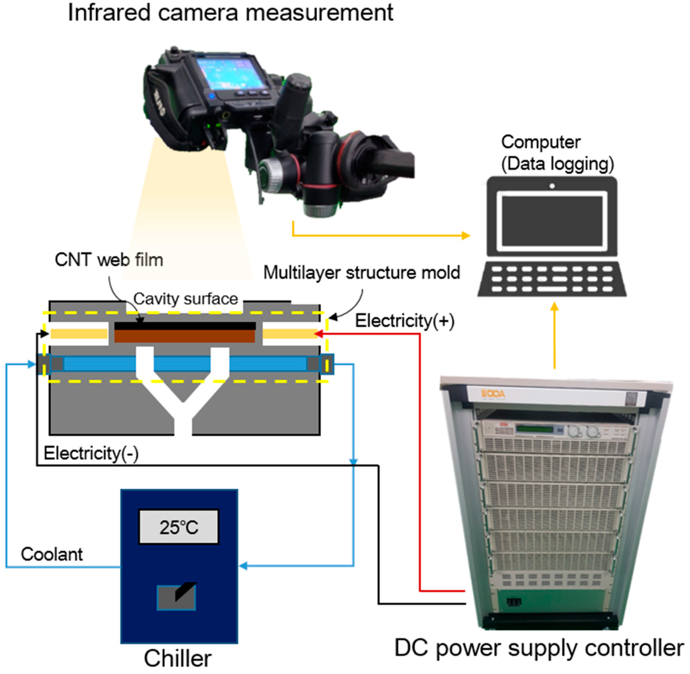
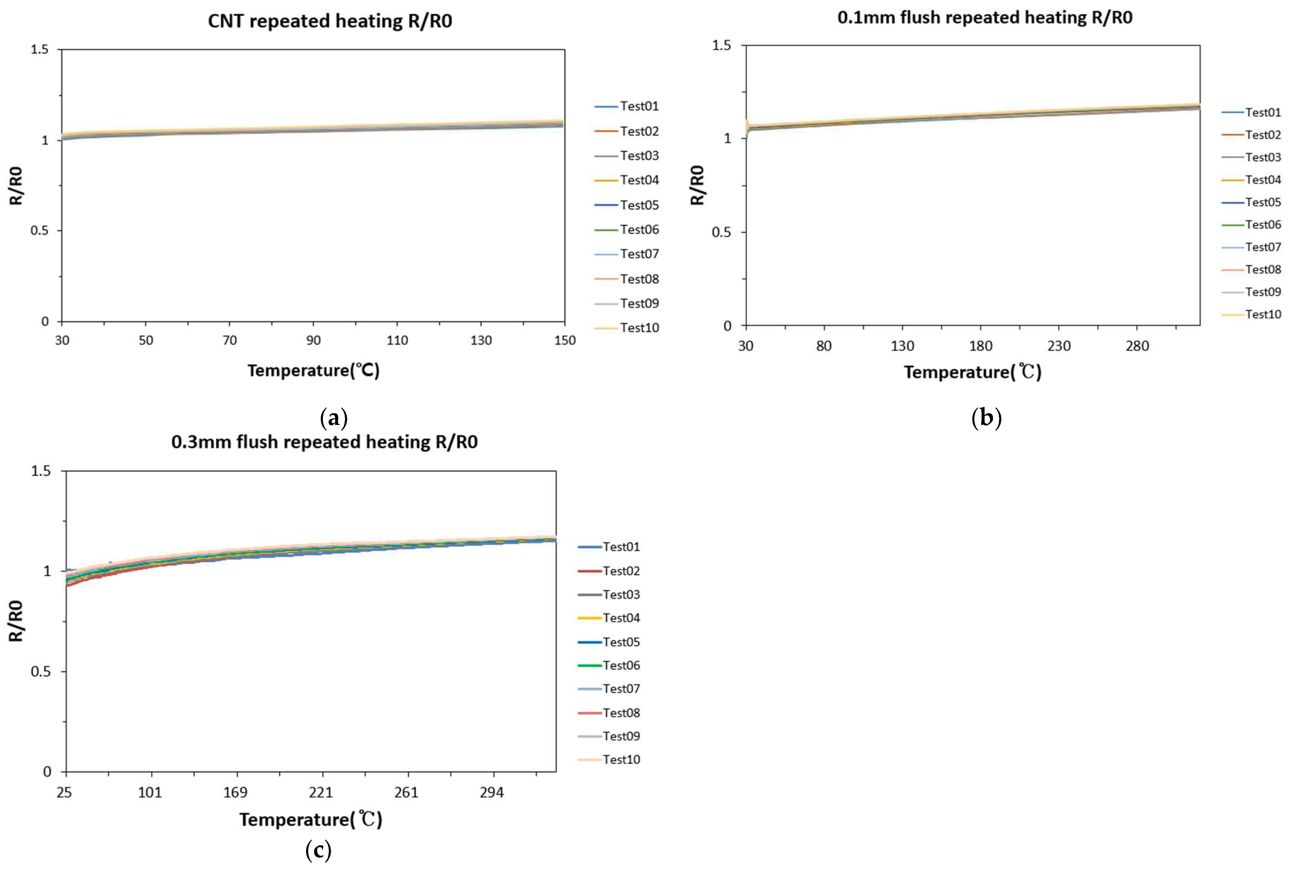
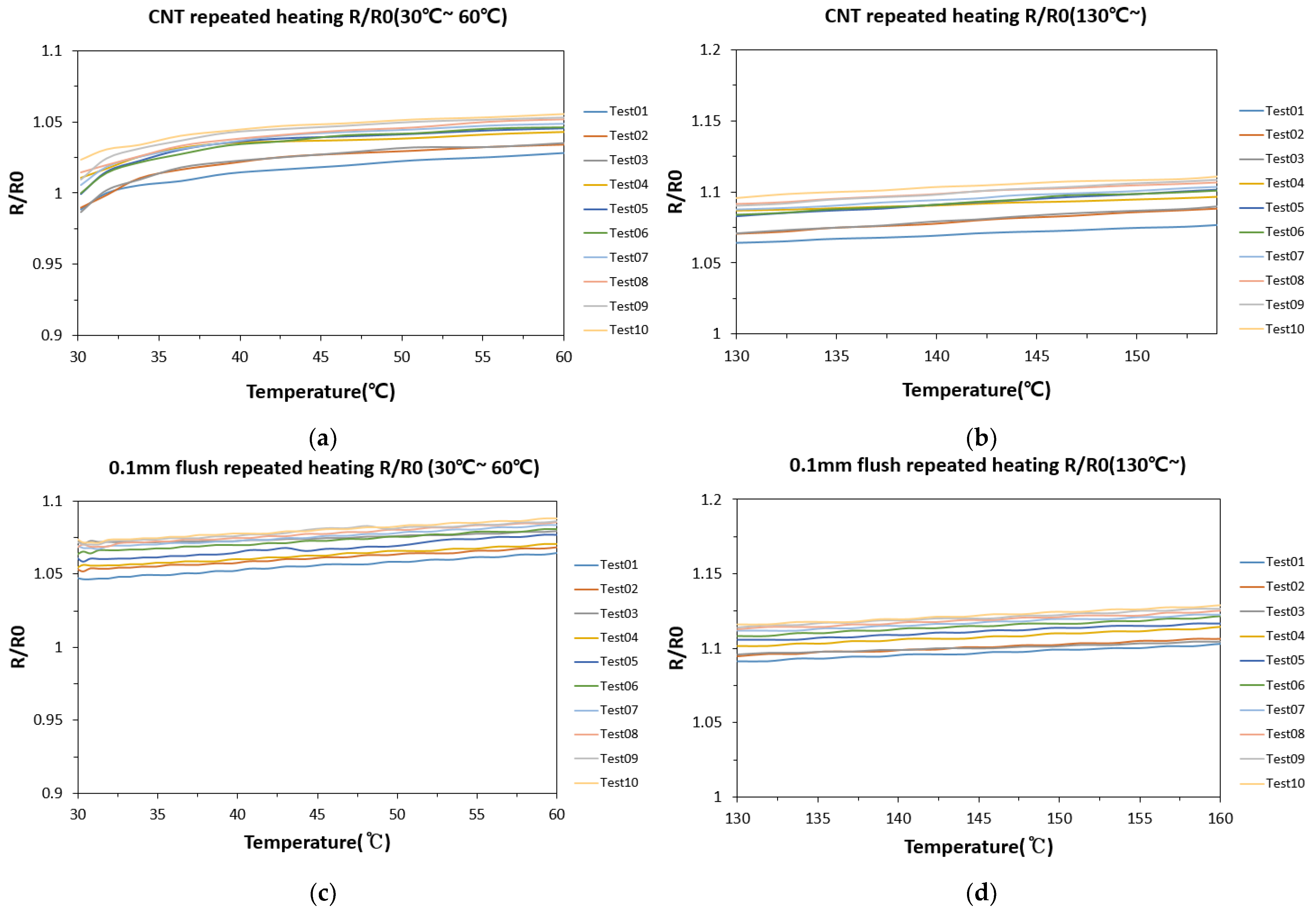
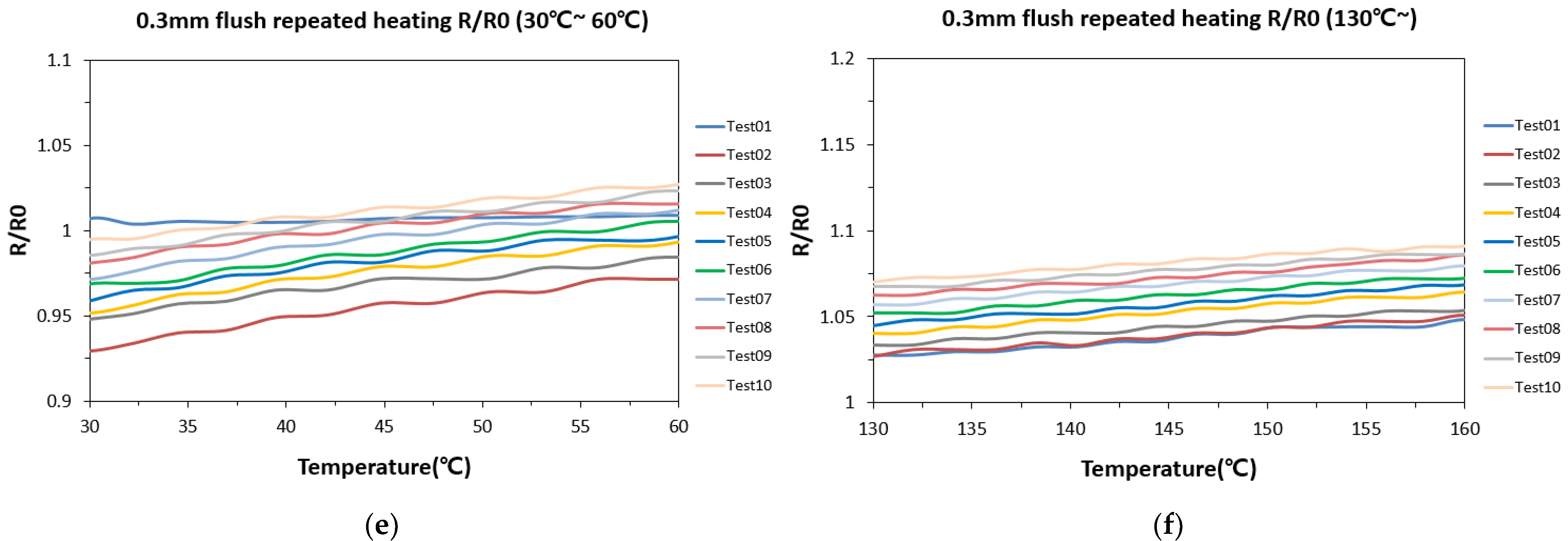
3.1. Flush Mold Heating Test

When 2.5 k W was applied to a single-phase mold without a flush, the temperature of the mold steel was heated to 150 °C. As the temperature increased, resistance increased, showing PTC (Positive Temperature Coefficient of Resistance) characteristics. Both showed PTC characteristics when heated regardless of the presence or absence of flush (see Figure 4). When heating the mold, the change in resistance was measured in the low-temperature range (30~60 °C) and high-temperature range (130 °C or above) (see Figure 5). The rate of change in the normalized R value in the low-temperature range was 2.4%. In the high-temperature range, it was 2.3%, and the change rate in resistance was similar across the entire temperature range. In the flush test mold, the flush between the busbar and the bottom insulator was set to 0 m m , 0.1 m m , and 0.3 m m , and power was applied to observe the change in resistance of the CNT web film. The variation rates of CNT web film’s normalized R with a flush of 0.1 mm and 0.3 mm were found to be 2.9% and 9.6% in the low-temperature range and 2.7% and 4.3% in the high-temperature range, respectively. In all experiments, the resistance change rate in the high-temperature section was lower than in the low-temperature section. That appears to be a characteristic of the resistance change converging and becoming constant by the aging phenomenon of the CNT web film when heated above a specific temperature. When the flush was 0 m m or 0.1 m m , resistance changes were similar to those in the low- and high-temperature ranges. However, when the flush was 0.3 m m , the resistance change in the low-temperature range was 2.2 times higher than that in the high-temperature range. In addition, when comparing the resistance of each repeated experiment in the low-temperature section, an abnormal phenomenon was observed in which the resistance decreased. When the flush inside the mold is over 0.3 m m , it seems to cause damage to the CNT web film during heating.

3.2. Raman Spectroscopy Measurements of CNT Web Film

CNT web film was measured using Raman spectroscopy to directly observe the damage to the CNT web film after repeated flush mold heating experiments. As shown in Figure 6, five points of the CNT web film were designated and observed. At the P1 point, the actual contact part and the non-contact part were separated and measured into P1-1 and P1-2 points, and the Raman measurement results are shown in Figure 7. The degree of defect in the CNT web film was confirmed through the D / G peak. The sample’s P0, P1-1, P1-2, P2, and P3 points with a flush of 0 m m presented D / G peaks of 0.18, 0.16, 0.18, 0.14, and 0.14 on average, respectively. Each point of the 0.1 m m sample presented   D / G peaks of 0.18, 0.18, 0.21, 0.35, and 0.39, respectively. Each point of the 0.3 m m sample presented D / G peaks of 0.23, 0.26, 0.41, 0.25, and 0.31. When there was no flush (0 m m ), similar peak values were presented at all points, and no defects appeared. However, the defect caused by the flush showed a maximum peak of 0.41 at the P1-2 point of 0.3 m m . Hence, a non-contact overheating defect occurs when the flush is over 0.3 mm.

3.3. Heat-Transfer Analysis by the Thickness of Layers

The heat-transfer efficiency was compared, as shown in Figure 8, by changing the thickness of each layer in the multilayer structure mold. To improve the heat-transfer efficiency of the multilayer structure mold and find the optimal thickness of each layer, comparisons of heating rates with varying material thickness and simulation analysis were conducted using the Ansys simulation tool. The detailed simulation setup is listed in Table 3. To verify the simulation model before optimization analysis, one-cycle heating performance was verified by comparing analysis and experimental data (see Figure 8e). The simulation model presented a maximum error of 12.6% during heating, but the maximum heating temperature was very similar, with an error of approximately 0.5%. The simulation model was verified with an average error of 9.4%. Based on this simulation model, the heat-transfer performance of each layer in the multilayer structure mold was analyzed. In Figure 8b, it can be seen that as the thickness of the CNT web film decreases, heat-transfer performance reaches its maximums at 10 μ m and 5 μ m . In Figure 8c,d, it can be seen that the heat-transfer performance increases as the insulator thickness increases and the thickness of the electrical insulator decreases, respectively. The maximum heat-transfer performance was achieved when the insulator thickness was over 5 m m and the electrical insulator thickness was 0.25 m m . Finally, the thicknesses of the multilayer structure mold’s CNT web film, insulator, and electrical insulator were selected as 10 μ m , 5 m m , and 0.5 m m , respectively. In the case of electrical insulators, thinner thicknesses improve heat-transfer performance, but for safety reasons, a thickness of at least 0.5 m m should be applied for electrical insulation. Additionally, the one-cycle heating performance of the RHCM mold with optimal thickness was compared to the CIM mold applied with cartridge heaters. It was confirmed that RHCM heats approximately four times faster than CIM.

3.4. Surface Temperature Uniformity

The heat-transfer analysis model was verified by comparing it with heating experiment data, reflecting the thickness of each layer of the final selected multilayer mold. As shown in Figure 9, a similar temperature distribution was observed during heating. According to the analysis model, the maximum temperature reached was 176 °C, while the experimental results showed a similar maximum temperature of about 177 °C. The maximum error between the simulation model and the experimental results was 12%, with the average error staying within 10%, indicating comparable behavior. Similar temperature trends were observed during the heating period, as shown in Figure 9c.
T u = 100 × 1 T t T p T p
In the experiment, the temperature uniformity T u is calculated as Equation (3) based on the target temperature of about 170 °C. T t is the target temperature, and T P represents the measured temperature at the point. Temperature uniformity was 95.7%, 97.8%, 99.3%, 96.8%, 99%, and 99% at points 1–6, respectively, with an average uniformity of 98% at the highest temperature point. In the CIM process, temperature uniformities at the same point were 83.9%, 85%, 94.5%, 84.1%, 85.3%, and 95.8% at points 1–6, with an average temperature uniformity of 88.1%.

4. Conclusions

Problems that appear in the mold design stage for implementing a rapid heating process using CNT web film as a heat source were identified by designing variables. When applying CNT web film to multilayer structure molds, processing and assembly errors may cause non-contact areas called flush, damaging the CNT web film when heated.
(1)
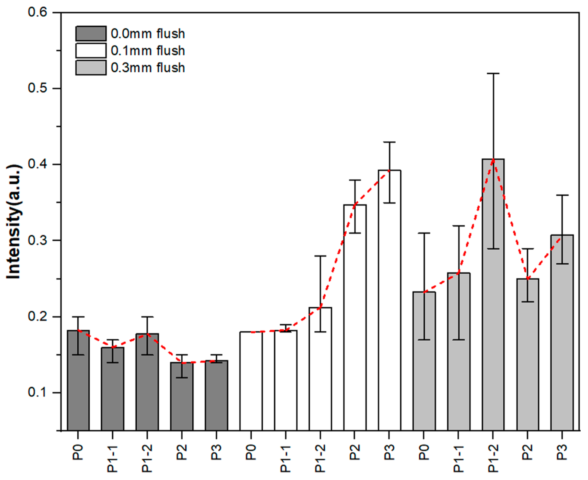
CNT web film was applied by setting flush of 0 m m , 0.1 m m , and 0.3 m m through a flush test mold, and the damage to CNT web film after heating was measured through changes in resistance and Raman spectroscopy.
(2)
When 0.1 m m flush was applied, the resistance change and D / G peak did not show much difference from the 0 m m flush sample, confirming that the flush was within the allowable value. However, when applying a 0.3 m m flush, the resistance change rates in the repeated experiment were highest in the low- and high-temperature ranges, and the D / G peak value of Raman spectroscopy was also highest. It was confirmed that it is inappropriate to apply CNT web film as a heat source in a multilayer structure with a flush of 0.3 m m or above. As the flush increases, the non-contact area of the CNT web film becomes more extensive, and it is relatively overheated during heating, confirming that the effect of oxidation is more significant than in other areas. For the stable implementation of a rapid heating multilayer structure mold with a CNT web film, it is necessary to design the flush level of the multilayer structure to be less than 0.3 m m .
(3)
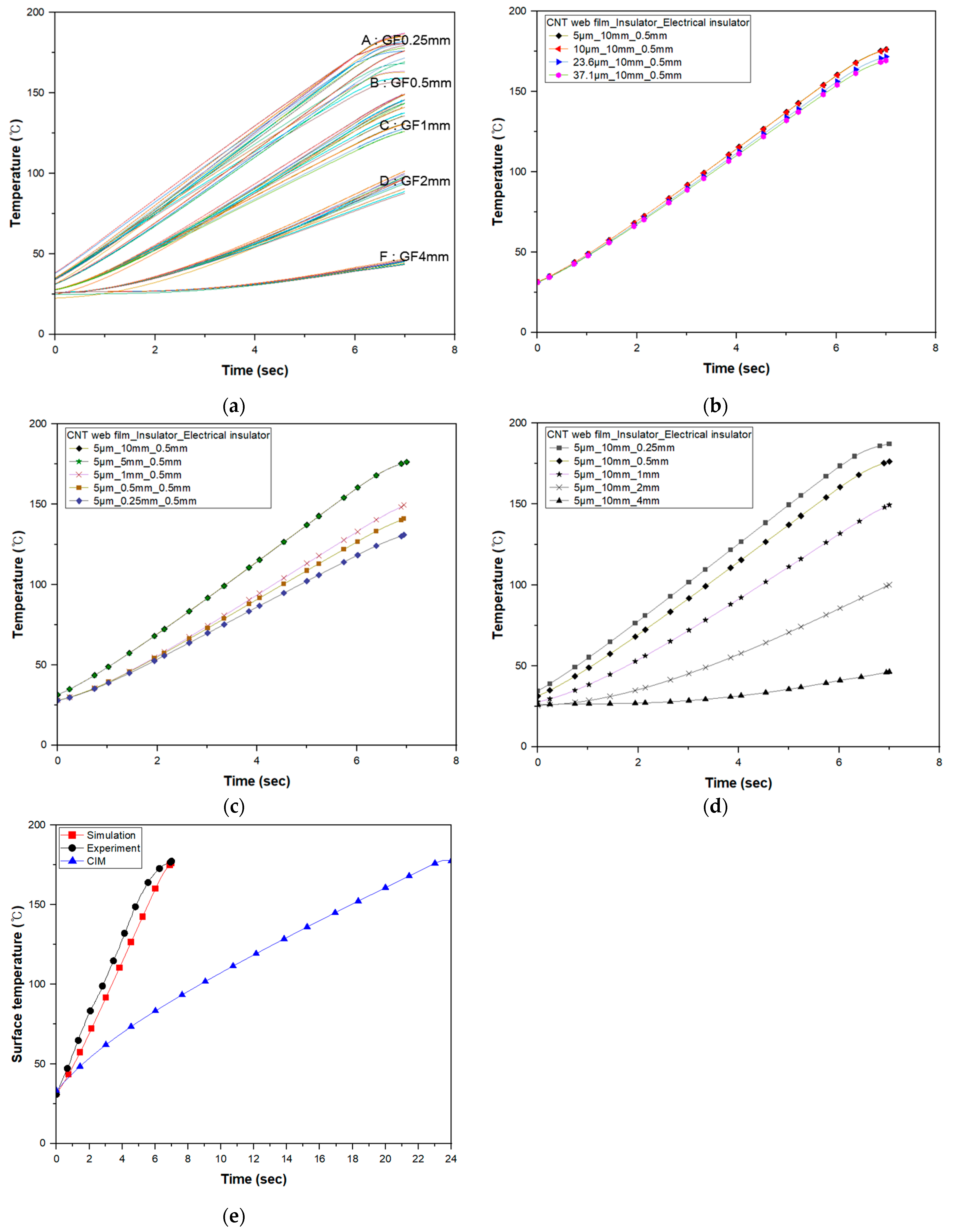
Optimization analysis was performed by combining the thicknesses of each material. The thicknesses of the CNT web film were 5 μ m , 10 μ m , 24 μ m , and 37 μ m . Insulator thicknesses were 0.25 m m , 0.5 m m , 1 m m , 5 m m , and 10 m m . The thicknesses of the electrical insulator were 0.25 m m , 0.5 m m , 1 m m , 2 m m , and 4 m m . As a result of the analysis, heat-transfer performance increased as the thickness of the CNT web film and electrical insulator decreased, and heat-transfer performance increased as the thickness of the insulator increased. The heat-transfer performance of the CNT web film converged below 10 μ m , and that of the insulator converged above 5 m m . Electrical insulators show better performance as they decrease. However, a thickness of at least 0.5 m m was selected for insulation safety. Heat-transfer performance in the direction of the cavity surface varies depending on the thickness of the insulator to block heat-transfer to the back of the mold and the electrical insulator located between the cavity surface and the CNT web film. The heat flow direction was toward the cavity surface when the electrical insulator was thinner than the insulator. That caused maximum heat-transfer performance to be observed.
(4)
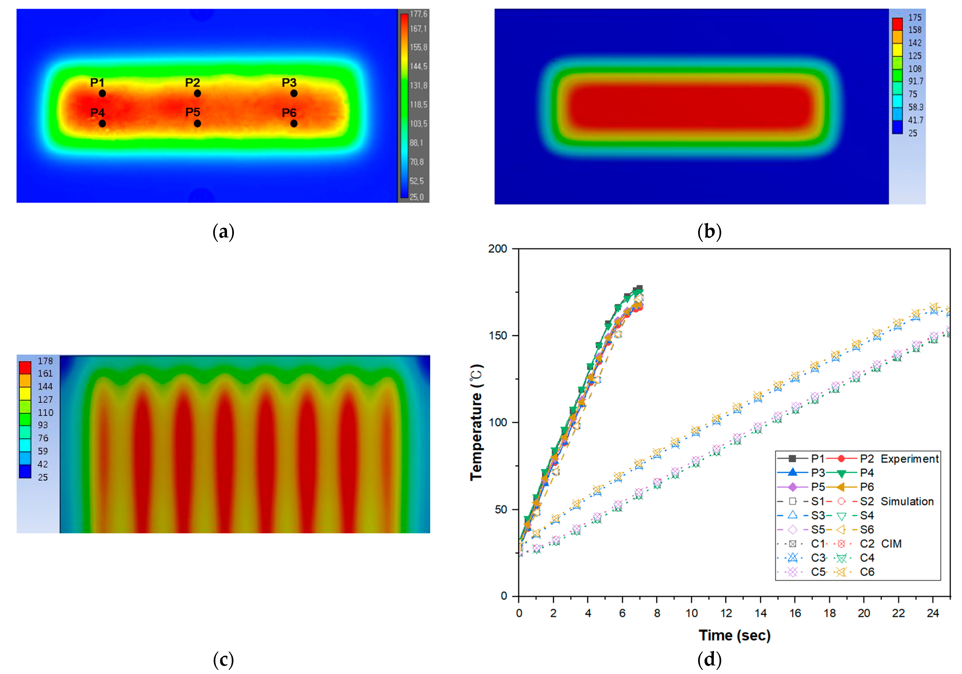
When comparing RHCM and CIM using cartridge heaters, the heating performance of the multilayer structure mold (RHCM) was heated more than four times faster than with CIM. The maximum heating rates in the RHCM mold and CIM mold were 21 °C/s and 5 °C/s, respectively. RHCM mold temperature uniformity was also higher by more than 10% for RHCM, with an average of 98% compared to 88% for CIM.
The rapid heating injection mold with the multilayer structure designed in this study has the advantage of a faster heating rate compared to the existing rapid heating technique. It also has significant advantages in production and cost, with low facility investment costs. In the future, the main variables of the rapid heating mold required for application to the injection process will be identified and reflected in the mold design to increase the durability and stabilization of the technology.

Author Contributions

Conceptualization, Y.K.; Formal analysis, H.L.; Investigation, H.L.; Methodology, Y.K. and W.C.; Validation, H.L.; Writing—original draft, H.L.; Writing—review and editing, Y.K. and W.C. All authors have read and agreed to the published version of the manuscript.

Funding

This work was supported by the Technology Innovation Program (Grant No. 20004272) funded by the Ministry of Trade, Industry and Energy, Republic of Korea.

Institutional Review Board Statement

Not applicable.

Informed Consent Statement

Not applicable.

Data Availability Statement

The original contributions presented in the study are included in the article, further inquiries can be directed to the corresponding author.

Conflicts of Interest

The authors declare no conflicts of interest.

References

  1. Park, K.; Sohn, D.-H.; Cho, K.-H. Eliminating Weldlines of an Injection-Molded Part with the Aid of High-Frequency Induction Heating. J. Mech. Sci. Technol. 2010, 24, 149–152. [Google Scholar] [CrossRef]
  2. Wang, G.; Hui, Y.; Lei, Z.; Guoqun, Z. Research on Temperature and Pressure Responses in the Rapid Mold Heating and Cooling Method Based on Annular Cooling Channels and Electric Heating. Int. J. Heat Mass Transf. 2018, 116, 1192–1203. [Google Scholar] [CrossRef]
  3. Chen, S.-C.; Wang, Y.-C.; Liu, S.-C.; Cin, J.-C. Mold Temperature Variation for Assisting Micro-Molding of DVD Micro-Featured Substrate and Dummy Using Pulsed Cooling. Sens. Actuators A Phys. 2009, 151, 87–93. [Google Scholar] [CrossRef]
  4. Chen, S.-C.; Jong, W.-R.; Chang, Y.-J.; Chang, J.-A.; Cin, J.-C. Rapid Mold Temperature Variation for Assisting the Micro Injection of High Aspect Ratio Micro-Feature Parts Using Induction Heating Technology. J. Micromech. Microeng. 2006, 16, 1783–1791. [Google Scholar] [CrossRef]
  5. Huang, M.; Tai, N. Experimental Rapid Surface Heating by Induction for Micro-injection Molding of Light-guided Plates. J. Appl. Polym. Sci. 2009, 113, 1345–1354. [Google Scholar] [CrossRef]
  6. Chen, S.-C.; Chang, Y.; Chang, Y.-P.; Chen, Y.-C.; Tseng, C.-Y. Effect of Cavity Surface Coating on Mold Temperature Variation and the Quality of Injection Molded Parts. Int. Commun. Heat Mass Transf. 2009, 36, 1030–1035. [Google Scholar] [CrossRef]
  7. Wang, G.; Zhao, G.; Li, H.; Guan, Y. Research of Thermal Response Simulation and Mold Structure Optimization for Rapid Heat Cycle Molding Processes, Respectively, with Steam Heating and Electric Heating. Mater. Des. 2010, 31, 382–395. [Google Scholar] [CrossRef]
  8. Theilade, U.A.; Hansen, H.N. Surface Microstructure Replication in Injection Molding. Int. J. Adv. Manuf. Technol. 2007, 33, 157–166. [Google Scholar] [CrossRef]
  9. Chang, P.; Hwang, S. Experimental Investigation of Infrared Rapid Surface Heating for Injection Molding. J. Appl. Polym. Sci. 2006, 102, 3704–3713. [Google Scholar] [CrossRef]
  10. Menotti, S.; Hansen, H.N.; Bissacco, G.; Calaon, M.; Tang, P.T.; Ravn, C. Injection Molding of Nanopatterned Surfaces in the Sub-Micrometer Range with Induction Heating Aid. Int. J. Adv. Manuf. Technol. 2014, 74, 907–916. [Google Scholar] [CrossRef]
  11. Chen, S.-C.; Jong, W.-R.; Chang, J.-A. Dynamic Mold Surface Temperature Control Using Induction Heating and Its Effects on the Surface Appearance of Weld Line. J. Appl. Polym. Sci. 2006, 101, 1174–1180. [Google Scholar] [CrossRef]
  12. Guerrier, P.; Tosello, G.; Nielsen, K.K.; Hattel, J.H. Three-Dimensional Numerical Modeling of an Induction Heated Injection Molding Tool with Flow Visualization. Int. J. Adv. Manuf. Technol. 2016, 85, 643–660. [Google Scholar] [CrossRef]
  13. Yao, D.; Kimerling, T.E.; Kim, B. High-frequency Proximity Heating for Injection Molding Applications. Polym. Eng. Sci. 2006, 46, 938–945. [Google Scholar] [CrossRef]
  14. Chen, S.-C.; Chien, R.-D.; Lin, S.-H.; Lin, M.-C.; Chang, J.-A. Feasibility Evaluation of Gas-Assisted Heating for Mold Surface Temperature Control during Injection Molding Process. Int. Commun. Heat. Mass. Transf. 2009, 36, 806–812. [Google Scholar] [CrossRef]
  15. Yao, D.; Kim, B. Development of Rapid Heating and Cooling Systems for Injection Molding Applications. Polym. Eng. Sci. 2002, 42, 2295–2481. [Google Scholar] [CrossRef]
  16. Kim, Y.; Choi, Y.; Kang, S. Replication of High Density Optical Disc Using Injection Mold with MEMS Heater. Microsyst. Technol. 2005, 11, 464–469. [Google Scholar] [CrossRef]
  17. Wang, G.; Zhao, G.; Wang, X. Development and Evaluation of a New Rapid Mold Heating and Cooling Method for Rapid Heat Cycle Molding. Int. J. Heat Mass Transf. 2014, 78, 99–111. [Google Scholar] [CrossRef]
  18. Jeng, M.-C.; Chen, S.-C.; Minh, P.S.; Chang, J.-A.; Chung, C. Rapid Mold Temperature Control in Injection Molding by Using Steam Heating. Int. Commun. Heat Mass Transf. 2010, 37, 1295–1304. [Google Scholar] [CrossRef]
  19. Lee, J.; Turng, L.-S. Improving Surface Quality of Microcellular Injection Molded Parts through Mold Surface Temperature Manipulation with Thin Film Insulation. Polym. Eng. Sci. 2010, 50, 1281–1289. [Google Scholar] [CrossRef]
  20. Yang, H.; Yilmaz, G.; Han, G.; Eriten, M.; Zhang, Z.; Yu, S.; Shi, M.; Yan, H.; Yang, W.; Xie, P.; et al. A Quick Response and Tribologically Durable Graphene Heater for Rapid Heat Cycle Molding and Its Applications in Injection Molding. Appl. Therm. Eng. 2020, 167, 114791. [Google Scholar] [CrossRef]
  21. Li, Y.-L.; Kinloch, I.A.; Windle, A.H. Direct Spinning of Carbon Nanotube Fibers from Chemical Vapor Deposition Synthesis. Science 2004, 304, 276–278. [Google Scholar] [CrossRef] [PubMed]
  22. Kim, H.W.; Ha, J.H.; Song, H.J.; Park, J.H.; Jeong, Y.J. Rapid and Durable Electric Heating Characteristics of Carbon Nanotube Web Film. Conf. Korean Soc. Precis. Eng. 2020, 1, 799. [Google Scholar]
Figure 1. Fabrication of CNT web film.
Applsci 14 02813 g001
Figure 2. Schematic view of RHCM experiment.
Applsci 14 02813 g002
Figure 3. RHCM multilayer structure mold: (a) test mold, (b) inside of the test mold, (c) cross-sectional view of A-A’, (d) each layer of the multilayer structure mold.
Applsci 14 02813 g003
Figure 4. Resistance variation of CNT web film by flush: (a) 0 mm flush, (b) 0.1 mm flush, (c) 0.3 mm flush.
Applsci 14 02813 g004
Figure 5. Resistance variation of CNT web film by flush and temperature range: (a) 0 m m flush at 30 °C < T < 60 °C, (b) 0 mm flush at 130 °C < T , (c) 0.1 m m flush at 30 °C < T < 60 °C, (d) 0.1 m m flush at 130 °C < T , (e) 0.3 m m flush at 30 °C < T < 60 °C, (f) 0.3 mm flush at 130 °C < T .
Applsci 14 02813 g005aApplsci 14 02813 g005b
Figure 6. Measuring points (a) 4 measuring points of CNT web film, (b) Detail points in P1.
Applsci 14 02813 g006
Figure 7. Results of Raman spectroscopy of CNT web film.
Applsci 14 02813 g007
Figure 8. Temperature response of multilayer structure mold: (a) total data of various thicknesses, (b) CNT web film thickness variation, (c) insulator thickness variation, (d) electronical insulator variation, (e) verification of simulation model and comparison of RHCM and CIM.
Applsci 14 02813 g008
Figure 9. Temperature uniformity of multilayer structure mold: (a) RHCM experiment temperature contour, (b) RHCM simulation temperature contour, (c) CIM mold temperature contour, (d) temperature response of 6 points.
Applsci 14 02813 g009
Table 1. Properties of the materials for the multilayer test mold.
MaterialComponentDensity
( g / c m 3 )
Conductivity
( W / m · K )
Specific Heat
( J / g · K )
Resistivity   ( O h m · c m )
NAK80Core plate7.841.330.4812.63 × 10−5
CNT web filmHeater0.41(In-plane) 14.65
(Out-of-plane) 600
0.7162.49 × 10−3
C1100Bus bar8.89390.790.3851.7 × 10−8
Glass fiber fabricElectrical insulator1.261.50.651 × 1025
ISOL600Insulator1.630.330.88-
Table 2. Thermal contact conductance of multilayer structure mold.
Materials Thermal   Contact   Conductance   ( W / m 2 · K )
Nak80Electric insulator2900
Electric insulatorCNT web film30,000
CNT web filmInsulator1000
Table 3. Multilayer structure mold CNT web film, insulator, and electrical insulator optimizing parameters.
Material Thickness   Levels   ( m m ) Power   Density   ( W / c m 2 )
CNT web film0.0050.010.0230.037 57
Insulator0.51241057
Electric insulator0.250.512 457
Disclaimer/Publisher’s Note: The statements, opinions and data contained in all publications are solely those of the individual author(s) and contributor(s) and not of MDPI and/or the editor(s). MDPI and/or the editor(s) disclaim responsibility for any injury to people or property resulting from any ideas, methods, instructions or products referred to in the content.

