Featured Application
This work will help in the development of new methods for fixing test specimens to the exciters aimed at increasing the safety of vibration testing and the time efficiency of test preparation.
Abstract
The use of electric drives and energy storage devices in vehicles presents fresh challenges for system designers. Among these is addressing the susceptibility of battery packs to mechanical vibrations, necessitating vibration testing. In failure scenarios, like a battery fire, swiftly detaching the battery pack from the vibration platform is vital. It is also essential to ensure that the mounting system—fixture and fastener—effectively transfers vibration between the exciter and the battery pack. The article discusses the basic requirements for the fixture of specimens subjected to vibration testing and fastening it to a slip table of head expander, giving a better understanding of its role. It then presents the results of a theoretical analysis of the fixing forces and their laboratory testing using prototype customized fastening solutions with potential for use in vibration testing. The results of the conducted research and analyses demonstrate that non-standard mounting techniques have limited potential to replace screw mountings in vibration testing, particularly as fully universal techniques. However, the generated mounting forces, with potential resulting from the possibility of tailored implementation of the tested mounting techniques in the design of tables or head expanders, appropriately designed, justify further research work in this area.
1. Introduction
1.1. Lithium Ion Battery Packs in Electric Vehicles and Their Safety Issues
Over the years, lithium ion batteries (LIBs), introduced by Sony [1] in 1991, have established themselves as the dominant choice for powering a wide array of consumer electronics due to their high energy and power density compared to other types of batteries, as well as falling costs. Lithium ion batteries have also been widely adopted in the automotive industry, significantly propelling vehicle electrification. This is demonstrated by the increasing global production of various EVs, exceeding 10 million units in 2022, with forecasts for 2023 projecting sales of about 14 million units [2,3], including battery electric vehicles (BEVs), hybrid electric vehicles (HEVs), plug-in hybrid electric vehicles (PHEVs), and fuel cell electric vehicles (FCVs).
Electric vehicles use lithium ion batteries in the form of battery packs, which consist of connected cells, as shown in Figure 1 [4]. These cells are often first assembled into modules and then combined into battery packs. A battery pack also includes a battery management system (BMS), battery enclosures, thermal management system (TMS), connectors and cables, a voltage regulator, and safety features [5].

Figure 1.
Cell, module, and battery pack utilization of lithium ion batteries.
In automotive engineering, the design of battery packs involves a large number of cells, their complex interconnections, and monitoring systems. This approach not only offers benefits but also entails risks, which include the following [6,7,8,9,10,11]:
- Voltage and temperature sensitivity—LIBs are sensitive to high temperatures and voltage irregularities, which can lead to malfunctions or degradation of battery performance;
- Electrical hazards—short circuits and overcharging, which can cause overheating, fire, or explosion may occur;
- Physical damage risks—physical impacts during vehicle collisions lead to safety hazards, like short circuits or leakage of hazardous materials;
- Environmental hazards during transport—the batteries pose risks during transportation due to their reactive nature;
- Fire and explosion hazards—due to the chemical composition and energy density of Li-ion batteries, there is a risk of fire and explosion, which can be caused by different types of abuse (e.g., thermal abuse, electrical abuse, and mechanical abuse) and internal short circuit;
- Thermal runaway risk—the dense packing of a large number of lithium ion batteries (LIBs) in a battery pack increases the risk of thermal runaway (TR) due to the self-heating of the LIBs;
- Risk of cascading failures—in battery packs, failure in one cell can lead to a cascading effect, causing widespread damage to the entire battery system.
1.2. Safety Standards for Lithium Ion Batteries
The widespread adoption of lithium ion battery technology with the concomitant risks of their use in vehicles has necessitated the development of global standards and regulations to ensure their safe introduction into automotive industry [6,7,11]. The United Nations Economic Commission for Europe (UNECE) issues type approval regulations, creating consistent technical guidelines for vehicles and components. In the US, the National Highway Traffic Safety Administration (NHTSA) sets safety requirements through the Federal Motor Vehicle Safety Standards (FMVSS) [6,7].
The standards focus on different aspects, such as the following [6,7,11,12,13,14,15]:
- Electrical safety tests (e.g., IEC 62133, UL 2054, UL1642)—overcharge, short-circuit, over-discharge;
- Mechanical safety test [7]—vibration and shock tests (e.g., IEC 62133, UN 38.3, ISO 12405, ECE R100), the nail penetration test (e.g., IEC 62133, UL 1642), and drop testing (e.g., IEC 62133, UN 38.3;
- Thermal safety tests environmental (e.g., IEC 62133, IEC 61960, UL 1642, ECE R100, UN 38.3)—high/low temperature exposure, thermal cycling;
- Other environmental safety—humidity tests (e.g., IEC 60068-2-78), low pressure (altitude) tests (e.g., IEC 62133, UL 1642), dust and water resistance (e.g., IEC 60529), and the salt spray test.
These tests help to identify weak points in battery systems and evaluate their behavior in harsh situations. The result of revealing weaknesses in the batteries under investigation may be mechanical or electrical damage to the batteries and, as a result, initiation of a thermal runaway (TR) of the battery, ending in a battery fire. TR is a chain reaction causing overheating, combustion, or even explosion of batteries. TR can stem from both external factors, like abuse, and internal factors, like manufacturing impurities. The severity of the consequences depends on multiple variables, such as the state of charge, charging/discharging rate, cell type, history, and materials. International, national, and regional standards set pass/fail criteria for battery tests. For instance, some standards, like UN/ECE-R100.02 [13], UL 2580 [14], and ISO 12405-4 [16], require no fire, explosion, rupture, or leakage under foreseeable misuse.
1.3. Safety of Lithium Ion Battery Testing
The TR process results in fires accompanied by the release of vast amounts of heat [9,17]. In the case of using a battery pack in an electric vehicle, extinguishing fires in individual cells is extremely challenging due to their integration into modules and the entire battery pack being covered by the battery pack enclosure. This often leads to fire and the destruction of the entire vehicle [18,19].
Safety verification of battery packs during tests at research facilities carries a higher likelihood of such fires. With similar difficulties in extinguishing fires in integrated cells and the substantial heat generated, there is an increased risk of serious damage to expensive research infrastructure and threats to the health and life of the research personnel. The risk is further amplified by the production of large quantities of highly toxic gases.
The simplest way to ensure the safety of battery pack vibrational tests is to conduct them in isolated rooms, accepting the risk of ignition of the testing device without additional protections. There are also trends in increasing the safety levels by attempting to control fires at vibration test stations, such as the setup by Data Physics [20], which implemented sample shielding and a water mist fire suppression system. Despite these shields, this solution still exposes the environment to the effects of ignition, such as the emission of harmful gases and hot fragments detaching from the batteries. Leaving a burning battery on the vibration exciter head causes the transfer of a large amount of heat to the inside of the exciter and risks damaging it.
The presented risks associated with battery testing, related to the significant health hazards for the personnel and economic risks for research laboratories, necessitate the search for effective methods of protecting personnel and battery testing equipment during tests in testing laboratories. Particularly important are vibration testing laboratories using expensive testing equipment—electrodynamics exciters (shakers), slip tables and sensors, and acquisition systems.
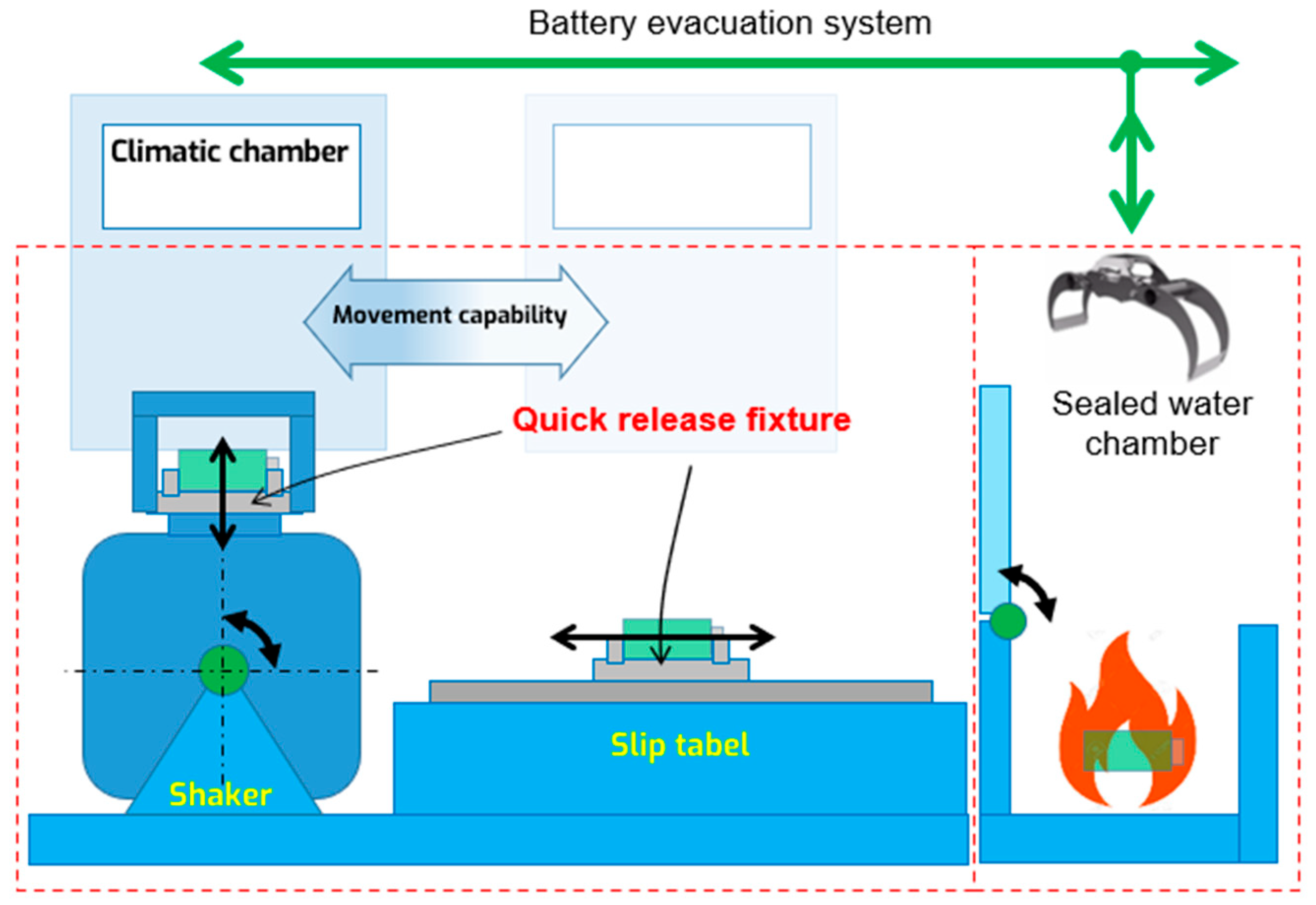
Given the difficulties in extinguishing fires in lithium ion cells enclosed in battery pack casings, and the harmful effect of high temperature on the vibration exciter in the testing laboratory, it is advisable not to isolate the battery pack in which thermal runaway has begun at the station but to quickly evacuate it from the vibration table (a headexpander or slip table) to, for example, a fire-extinguishing chamber filled with water, which according to the literature is the most efficient method of extinguishing a fire [21]. Such a system was prototyped by the ENVIBRA Research & Development Group as part of the project “High fire safety stand for vibration testing of electric vehicle battery modules and full battery packs”; a schematic of the system is shown in Figure 2. In addition, the chamber can also absorb toxic gases and store them in a sealed tank for later disposal. In the absence of a fire, the stand can be used to observe and monitor the behavior of the sample after the vibration tests.

Figure 2.
Innovative concept of protection for the battery pack test equipment.
The implementation of this system for protecting the infrastructure and extinguishing the battery is hindered by the currently used method of attaching the battery to the vibration table on the vibration test stand—with dozens to hundreds of bolts—requiring tens of minutes for disconnecting the battery from the stand. The large number of fasteners is necessary due to the need for a rigid grip on the battery, ensuring the transmission of vibrations from the exciter to the specimen or the device under test (DUT)—in this case Li-ion battery packs—without changes in amplitude beyond normative tolerances.
A solution to the problem would be to use a fastening (clamping) system that has the ability to quickly disconnect, which would in turn allow rapid evacuation of the battery pack from the test stand. But it is also essential to ensure that the mounting system effectively transfers vibration between the vibration exciter and the battery pack.
1.4. Aim of the Research
The aim of the manuscript is to present the results of a theoretical analysis and experimental tests on the feasibility of using specimen (DUT) assembly techniques that allow for their quick disconnection from the vibration table. This takes into account, on the one hand, the multiplicity of quick disconnecting options, and on the other hand, the ability to properly transfer vibrations between the table and the sample being tested.
The manuscript is organized as follows. Section 1 presents the background of the problem of fire hazards during the testing of electric car battery packs and the innovative concept of rapid removal of batteries from the test stand.
Section 2 presents the basic assumptions for the conducting of vibration testing focusing on the existing methods of mounting (fastening) test specimens to a vibration table with a discussion of the requirements for mounting methods.
Section 3 analyzes potential non-standard mounting techniques, reviewing the potential of vacuum, electromagnetic, and mechanical techniques to generate clamping forces, along with an analysis of their other advantages and disadvantages from the standpoint of vibration testing.
Section 4 presents a study of prototype quick disassembly mounts made using vacuum and electromagnetic mounts to experimentally evaluate the ability of these mounts to properly transmit vibrations from a vibrating table to the test specimen.
Section 5 summarizes the results of the conducted theoretical analysis and the realized experimental tests.
1.5. The Paper’s Contribution to the Field of EV Battery Pack Vibration Testing
This paper makes a substantial contribution to the field of EV battery pack vibration testing. It summarizes the risks of usage and testing of lithium ion batteries (LIBs). It critically evaluates traditional methods of DUT fastening during vibration testing and introduces innovative alternative solutions aimed at improving both safety and efficiency in vibration testing. It explores the feasibility of utilizing vacuum and electromagnetic fastening systems as potential alternatives to conventional screw connections for fastening EV battery packs during vibration tests, thereby reducing setup and takedown times. The paper outlines the potential benefits of these non-standard mounting techniques. Building upon background information about fixture and fastening requirements for vibration testing and providing technical data on alternative fastening devices, the paper conducts a comprehensive theoretical analysis and experimental investigations. It compares crucial aspects of these methods, including the cost of ready-to-use clamps, mass per fixture surface, fastening force, and battery disconnection time. Additionally, it provides an experimental validation of their transmittance capabilities and the maximum value for sinusoidal sweep tests. The research findings enrich academic discourse and have practical implications for improving the reliability and safety of EV battery pack vibration testing.
2. Mechanical Vibration Tests
Mechanical vibration tests are one type of tests performed to evaluate battery safety, as vibrations are an unavoidable occurrence during the exploitation of every vehicle. ISO 12405 specifies test procedures for lithium ion battery packs and systems which are connected to the electric propulsion system of electrically propelled vehicles [16]. There are tests which are performed for battery packs/systems and those which are used for electric/electronic devices [22].
Vibration profiles simulate real-world conditions and aim to identify design flaws and enhance battery durability. The test described in the paper [23] showed that a standard vibration test for Li-ion batteries should cover a wide frequency range with a lot of low-frequency content. The frequency content must be well above 200 Hz, or alternatively a separate test should be carried out for electronic devices with higher-frequency content.
Various standards and regulations prescribe various vibration testing methods, employing sine wave (fixed frequency, sweep and resonance) and random profiles. These profiles stem from measurements in conventional vehicles at locations relevant to EV battery installation. Vibration test profiles specified in standards typically derive from guidelines in UN 38.3:2019 [12], IEC 60068-2-64:2008 [24], or SAE J2380_202112 [25]. Different testing conditions are applied for battery packs (up to 200 Hz) and cells (up to 2000 Hz), reflecting the variance in mass of the battery device under test (DUT). Throughout the test, the DUT undergoes predetermined vibration levels designed to mimic the operational lifecycle’s exposure to vibrations.
2.1. Vibration Tests Equipement
Mechanical vibration tests are performed using the following essential components [26,27,28]:
- Electrodynamic vibration exciters (shakers)—devices producing mechanical vibration based on an electrical current provided from a power amplifier; when the armature coils are supplied with an alternating current, they produce an alternating magnetic field which will causes the armature to move;
- Slip plate (table)—the slip table is placed on an extremely smooth stone surface and a hydraulic pump delivers oil through holes in this stone, reducing friction between the slip table and the surface on which it rests, meaning that the table is excited by horizontally oriented shakers;
- Power amplifiers—supplies the vibrator with the electric power necessary to generate vibration motion according to a control signal from closed-loop control system;
- Accelerometers—measures the vibration motion; during vibration tests they allow researchers to verify the vibratory levels reached by chosen DUT regions;
- Closed-loop control systems—allow researchers to check and control the vibration levels on the vibrator table according to the specified values for the test;
- Fixture—connects the DUT and the vibrator moving part and transmits the vibratory motion to the DUT.
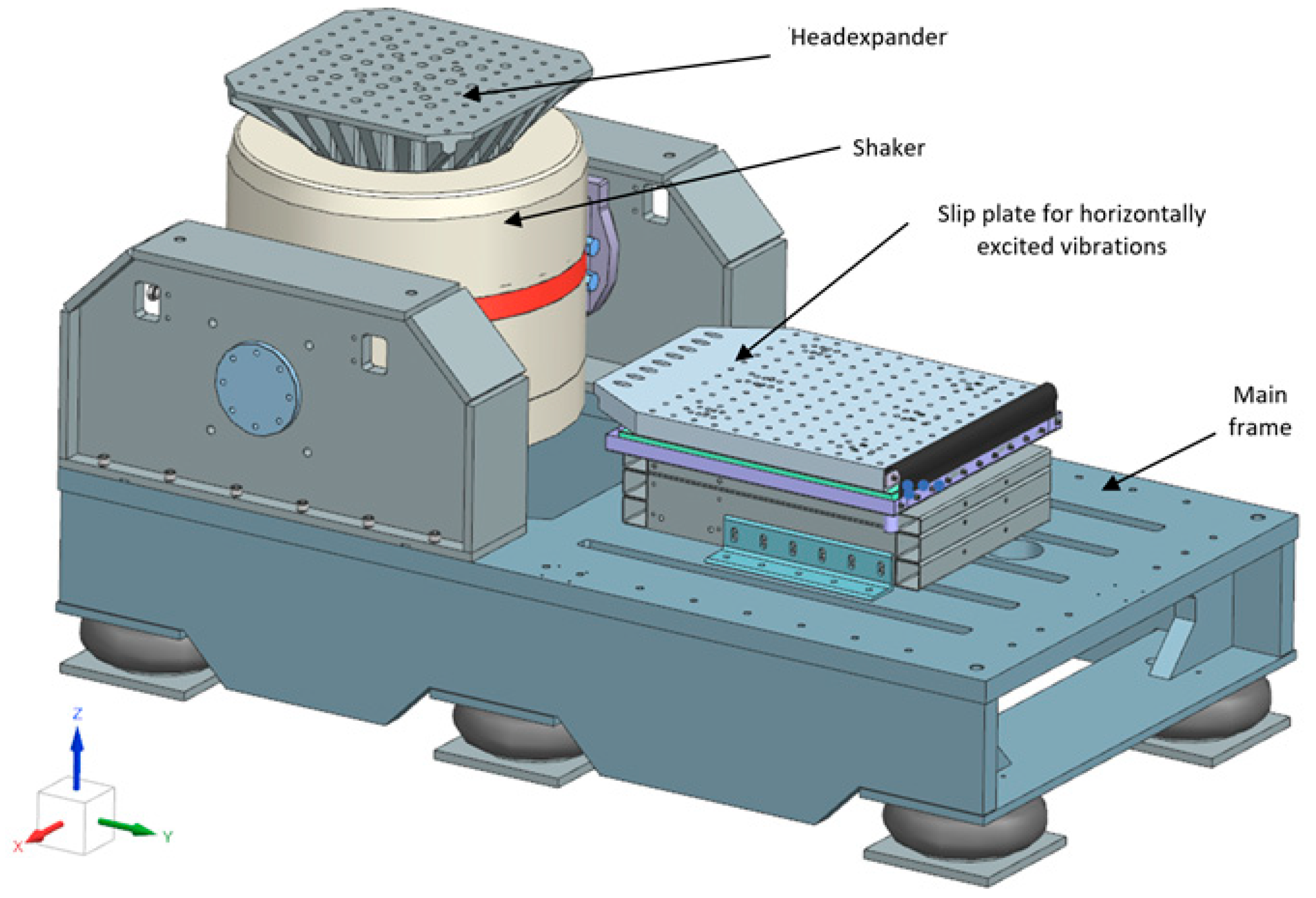
Using the aforementioned equipment, it is possible to subject the test samples to forced vibration signals, such as sinusoidal (sine wave), sweep sinusoidal, random, and shocks. These signals can be used to conduct durability tests, multiaxial vibration tests and simulations of vibrations occurring during transport. The construction of such a research workstation is shown in Figure 3.
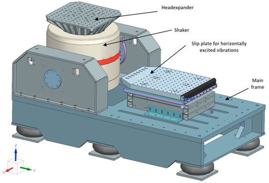
Figure 3.
Electrodynamic shaker for vertical vibration tests with a head expander and for horizontal vibration tests with a slip plate (table).
Commercially available electrodynamic shakers usually cover the useful operating frequency range between 5 Hz and 2000 Hz [28]. The force generated by an electrodynamic vibrator varies according to the input signal, which can be periodic, transient, or random, or a combination of all those types. The maximum acceleration provided by the vibrator to the DUT depends on the total moving mass (fixture + DUT + armature).
In order to meet the standards required for vibration testing at variable temperatures (−40 °C to +120 °C), temperature and humidity chambers superimposed on the inductor are also used.
2.2. Vibration Test Fixtures
In vibration testing, a vibration test fixture and its fasteners play crucial roles in ensuring accurate and reliable test results.
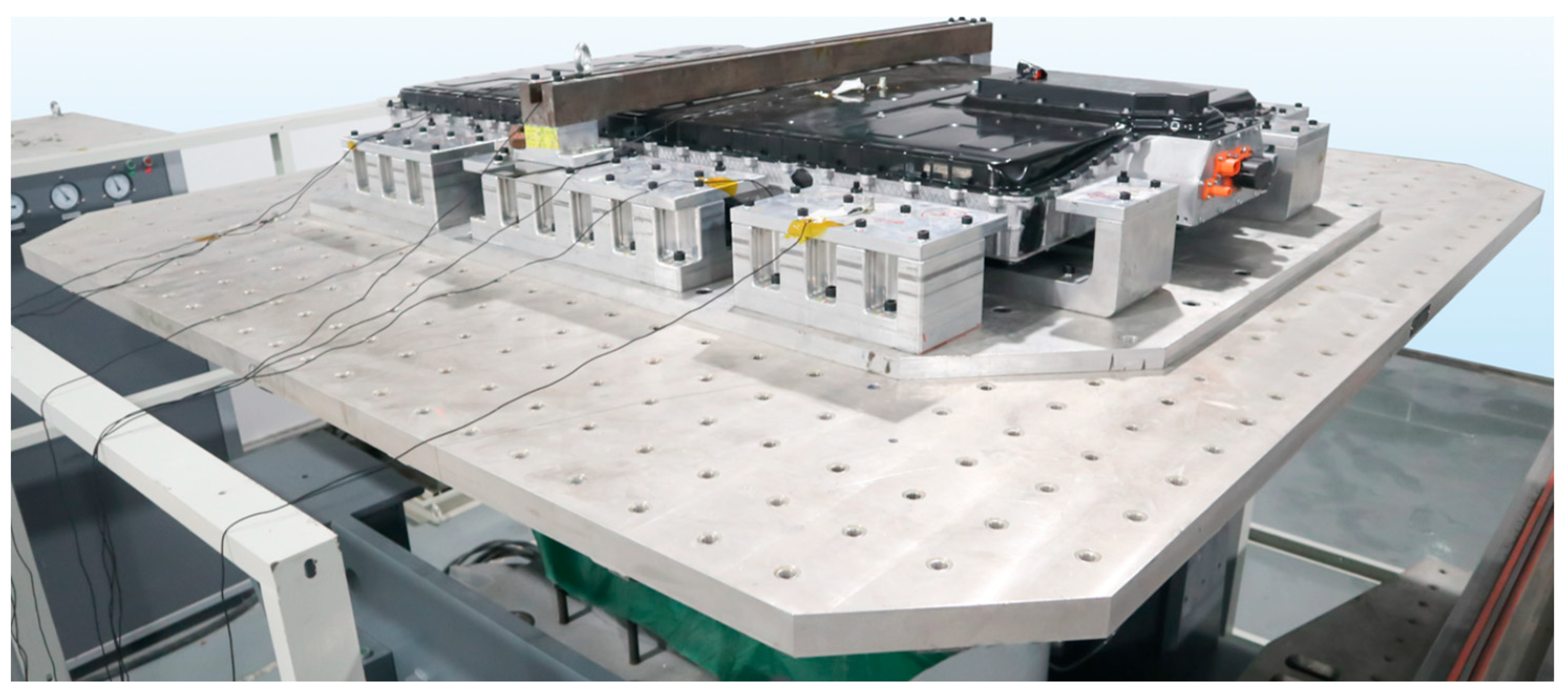
A vibration test fixture is a specialized device designed to securely hold and position the DUT or specimen during a vibration test, as in Figure 4. The primary purpose of the fixture is to simulate (together with the rest of the vibration test equipment) the real-world conditions under which the DUT will operate, allowing for accurate assessment of its performance, durability, and potential failure modes under vibration.
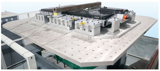
Figure 4.
Examples of a car’s battery pack fastened to the fixture on a slip table [29].
The main reason to fabricate a vibration test fixture is that it is not possible to mount the DUT directly to the vibration table or armature due to the following issues:
- The DUT mounting hole pattern not matching the vibration table hole pattern;
- The DUT size being much bigger than the size of the armature;
- The necessity for the DUT to be mounted in a certain orientation (for example: car audio systems, aircraft avionics, unmanned aerial vehicle cameras, etc.).
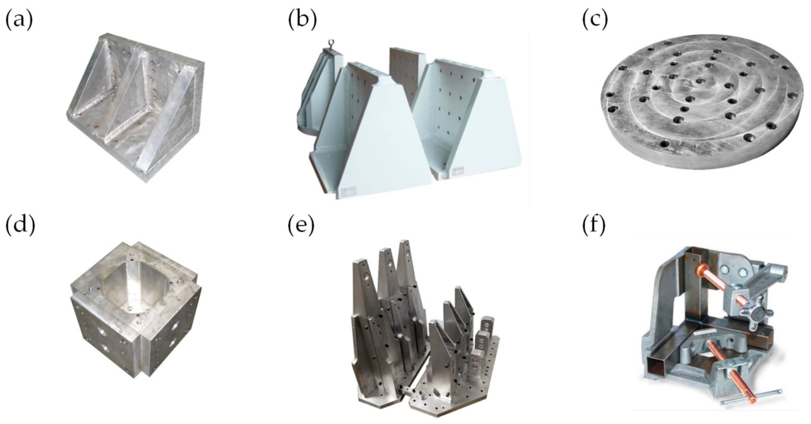
Figure 5 shows the standard fixture shapes, like L, T, plates, cubes, or a tri-axis, which are used for DUTs with flat mounting surfaces. For DUTs with complex shapes or mounting points, custom fixtures are created specifically for a given object [30,31].

Figure 5.
Examples of standard shape vibration test fixtures: (a) L type, (b) T type, (c) plate, and (d) cube. Special test fixtures: (e) custom fixture and (f) tri-axis fixture (on the base [30,31]).
There are many requirements for the vibration test fixtures, such as the following:
- 1.
- The shape of the fixture—the fixture for attaching the DUT to the vibration equipment must match the shape of the exciter table and fit the test object. It utilizes specific points on the DUT, such as feet or screw holes, to replicate real-world force application. The DUT is mounted as it would be in actual use, but the fixture is designed to be stiffer to endure the intense vibrations of accelerated testing;
- 2.
- Transmissibility (most important)—defined as the ratio of output to input vibration acceleration amplitudes at each test frequency, crucial for vibration testing, it requires the fixture to evenly transfer vibratory energy to the DUT across all frequencies. Ideally, it should maintain unitary transmissibility within the test range, with minimal distortion. However, practical limitations, like weight and cost, lead to imperfections, causing resonance or attenuation in vibration transfer;
- 3.
- The Natural vibration frequency of a fixture should be lower than the required frequency in the tests to avoid resonance phenomena. An ideal fixture couples the motion from the vibrator to the DUT with high fidelity, with zero distortion at all amplitudes and frequencies used in the test. Practical limitations, like weight and cost, lead to imperfections, causing resonance or attenuation in vibration transfer;
- 4.
- Mass—the fixture should be lightweight to maximize the acceleration achievable by the vibration exciter, allowing for simultaneous testing of multiple samples and improved cost efficiency. Fixtures should be low profile and keep the sample as close to the system input as possible;
- 5.
- Stiffness—to achieve reliable results with good transmission and minimal resonance, the system must be stiff and rigid. High stiffness in the vibration test fixture is necessary for efficient force transfer from the table to the test object with minimal loss and distortion. A light yet stiff fixture minimizes unwanted cross-axial motion and ensures high-fidelity motion transfer;
- 6.
- Cost—the fixture should be as cheap as possible, while retaining the aforementioned qualities. This depends on material and machining costs, but the fixture can also influence the cost of test preparation due to the labor costs connected with the device under test installation time and the later orientation changing time.
2.3. Standard Test Fixtures Fastening Methods
The device under test must be fastened to the fixture and the fixture has to be fastened to the head expander or the slip table. Technically, this is not the best choice when it comes to preventing relative motion, but it is the best choice if the fixture has to be used for different DUTs.
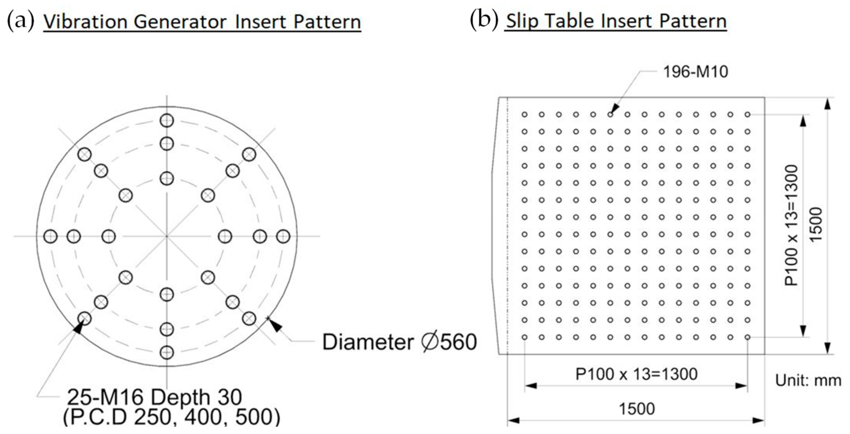
Head expanders and slip tables contain stainless steel threaded inserts, arranged according to a standard or client pattern—an example is shown in Figure 6. The choice of insert pattern depends on certain factors, such as the type of test object, its shape and size, the required attachment method, and the desired test conditions. Manufacturers of vibration test equipment often provide a range of options for inserts, allowing users to customize the setup based on their specific testing needs. Common grid patterns that are often used in vibration test equipment are in millimeters (25 × 25, 50 × 50, or 100 × 100) or in inches (1″ × 1″, 2″ × 2″, or 4″ × 4″).
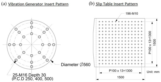
Figure 6.
Examples of the (a) head expander’s and (b) slip table’s insert pattern.
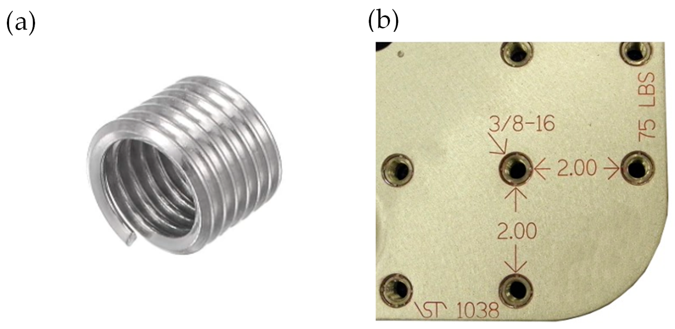
Figure 7 shows that the common thread sizes that are often used in vibration test equipment are the metric thread sizes M6, M8, M10, M12, and M16, and 1/4″-20, 3/8″-16, 1/2″-13, and 5/8″-11.

Figure 7.
An example of (a) an insert used in a head expander and (b) part of a head expander with the insert pattern size and thread indicated.
Using M8 grade 10.9 bolts for attaching the fixture to a sliding table or head expander, achieving a clamping force of 24 kN for a single bolt is theoretically possible. Even assuming that the clamping force is reduced due to insert properties to 70% of the mentioned value, this still amounts to about 16.8 kN. For a particular fixture design, the number of clamping screws can vary. For example, for a fixture base of 10 × 15 cm, using a 50 × 50 mm insert spacing pattern, it is possible to use 10 bolts to fasten the fixture only around the perimeter or 12 bolts to also fasten it with the internal bolts of the insert pattern. In the first case, a total force of 240 kN is obtained, and in the second case, the value is 288 kN. For a fixture base area of 150 cm2, a total average clamping force of either 1920 N/cm2 or 1600 N/cm2 is obtained. That force could be smaller if the fixture base were bigger and only the wedges on the perimeter were used.
The disadvantage of bolted connections is their large number (sometimes dozens) and, thus, the time required to precisely tighten so many bolts, fastening the DUT to the testing stand. Based on the vibration test equipment supplier’s experience in assembling these types of large specimens (1500 mm/2000 mm), the screw fasteners are placed every 100 mm on the perimeter of the specimen. Then, 70 bolts are used (2 × 1500 + 2 × 2000)/100). Assuming manual disassembly with an electric screwdriver (10 s for every bolt), the total disassembly time will be 700 s (almost 12 min). Manual assembly is more difficult, as it requires the use of a torque wrench (30 s for every bolt). This increases the assembly time to 35 min.
In the case of complex fixture shapes and difficult access to the bolts, the necessary time might be even longer. While the need to disconnect the fixture at the end of the test only means extended downtime for the vibration testing equipment, in the case of an emergency situation, in which the device under test requires immediate removal from the head expander or slip table, this is a critical disadvantage that precludes the rapid evacuation of the device under test.
3. Mechanical Vibration Tests
3.1. Mechanical Quick-Release Clamp
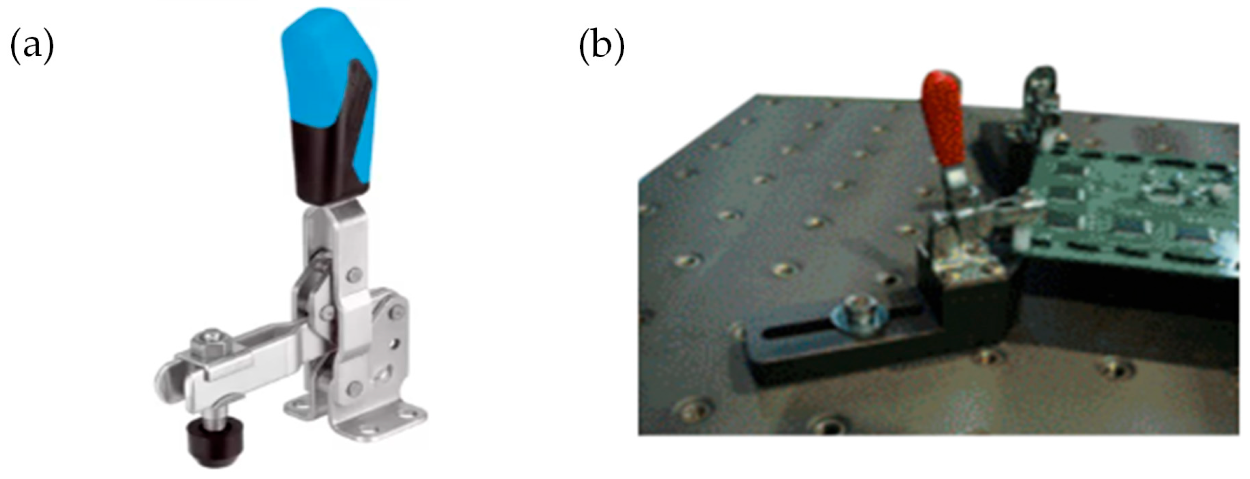
Analyzing the sources of knowledge about test specimen clamping methods, one also comes across information about the quick clamp fixture, which is an example of a quick-release fastening method. Such a solution, shown in Figure 8, is suitable for use on the production lines for small components, such as electronic items. With quick clamping, several tests can be repeated for the same product. The advantages of the quick clamp alone can significantly reduce both the installation time of test specimens and the hours of education and training. To sum up, the main advantages of the quick clamp fixture are the ease of use, getting started quickly, and reducing installation time.
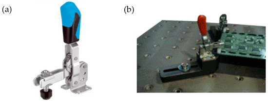
Figure 8.
An example of (a) a quick clamp fixture [32] used for (b) small electronic element fastening [33].
Such a quick toggle clamp is presented in Figure 8—it generates a fastening force of up to 1500 N. The mass of the clamp is about 0.13 kg. The larger clamp with a mass of 0.5 kg provides a clamping force of 2800 N [32,33].
3.2. Hydraulic Quick-Release Clamp
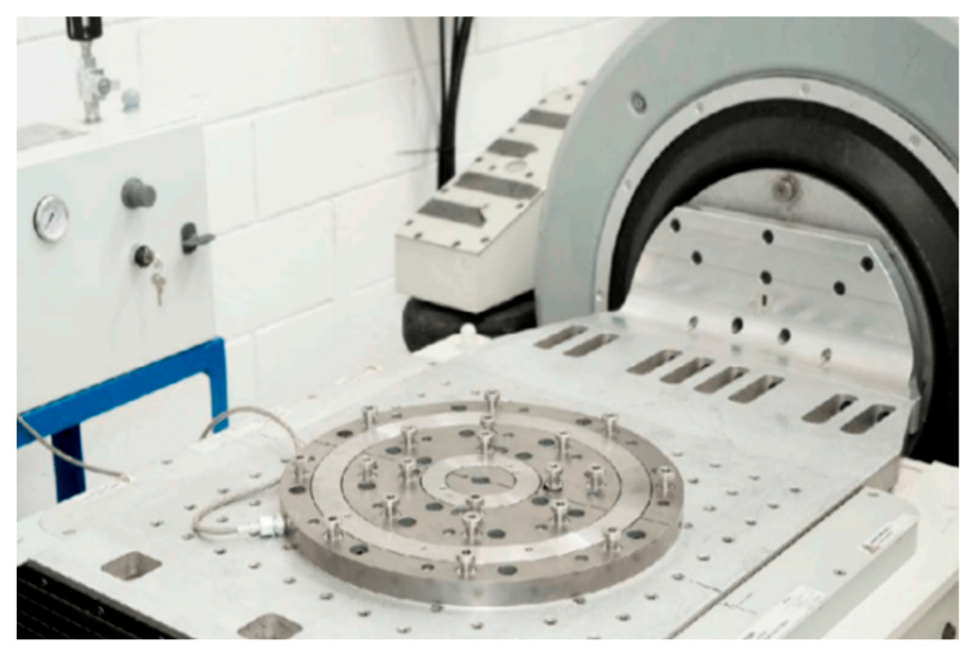
Another solution for a quick-release fastening method is a system which offers quick clamping functionality using hydraulic piston in a shape of a ring to tighten bolts and produce clamping force, fastening the DUT together with base plate of clamping device and fixture [34].
Instead of tightening the bolts by screwing them in, the same effect is achieved by shortening the distance between the bolt heads and the base against which the fixture rests by dividing the base into a fixed part (with bolts) and a movable part in the form of a hydraulic cylinder with a ring shaped piston. The solution is shown in Figure 9. The manufacturer states that the achieved clamping force is comparable with that generated with the use of bolts.

Figure 9.
Hydraulic quick clamp on a slip table.
This device significantly reduces the time needed to prepare for tests. Bolts no longer have to be tightened, so the manual work consists only of positioning the clamp. Operations that used to take up a considerable amount of time and, thus, increased the cost of the test, can take up as little time as half a minute. The manufacturer states that it takes less than 20 s to change the vibration axis of the DUT. Time savings multiply with each excitation axis tested.
The tightening is equivalent to the screws tightened to torque, and it has been positively evaluated both on the shaker and the slip table for sine, random, and shock tests in a frequency range up to 2000 Hz. The quick release of the whole setup makes it very safe and speeds up sample isolation in the event of a fire when testing the electric battery.
4. Potential Non-Standard Mounting Techniques Adaptable to Vibration Testing and Its Experimental Testing
4.1. Vacuum Clamping System
Vacuum clamping technology is a popular and effective method used in CNC (computer numerical control) machining to securely hold workpieces in place during the machining process. This technology relies on creating a vacuum between the workpiece and a clamping surface, typically a perforated table, to generate a strong holding force.
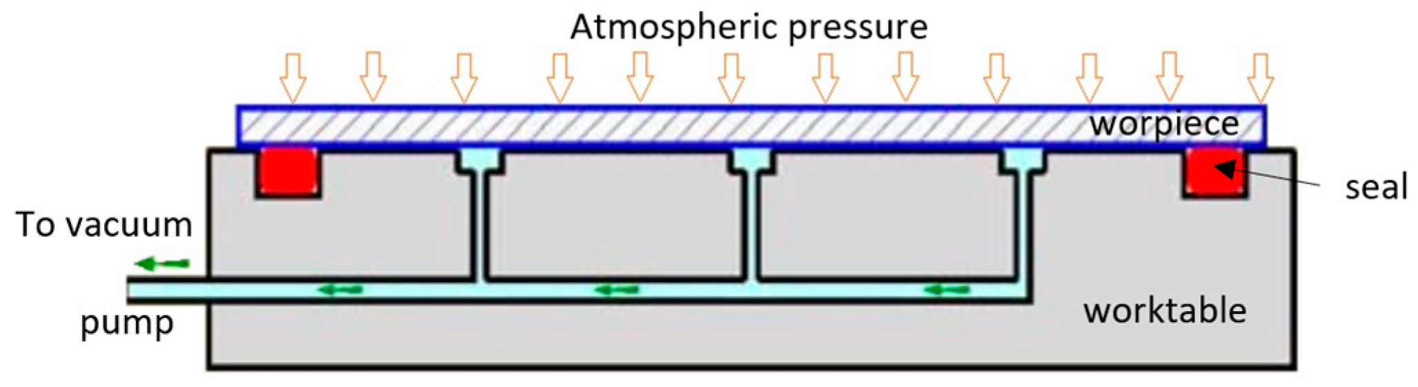
Vacuum clamping systems consist of a perforated worktable and a vacuum pump. The workpiece is placed on the perforated table, and a vacuum is created underneath the workpiece by the vacuum pump. As air is evacuated from the space between the workpiece and the table, atmospheric pressure forces the workpiece against the table, securely holding it in place. The schematic drawing of a vacuum clamp is illustrated in Figure 10.

Figure 10.
Schematic drawing of the cross section through the vacuum clamp (on the base [35]).
As the atmospheric pressure is 101,325 Pa (approximately 0.1 MPa or 10.1 N/cm2), the possible clamping force per 1 cm2 in an ideal vacuum will be equal to 10.1 N. In practice, commercially available vacuum pumps allow 80 to 90% of this value (8.1…9.1 N/cm2). For example, a workpiece with an area of 100 × 200 mm could be attached to the holder with a force of around 1600 N. Although this value is 8.4 times lower than the force exerted by a single M6 grade 10.9 bolt, it is often sufficient to hold a workpiece stationary during machining.
The clamping force was also tested experimentally on a rig (Figure 11) using a steel plate measuring 100 × 150 mm attached to a vacuum clamping system. The detachment force was set by an M12 screw, with the average break force at 936 N. The theoretical force was in a range of 947…1064 N, due to the smaller area (117 cm2) on which the vacuum was acting. Equation (1) is as follows:
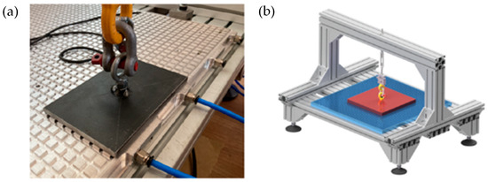
Figure 11.
Vacuum clamp during clamping force test: (a) vacuum clamp and (b) test stand.
The area being smaller than the resulting directly from the steel plate’s dimensions was due to the grid size (12.5) and the slot size (4 mm) of the vacuum table. The actual surface area of vacuum interaction on the test plate was (6 × 14.5 − 4 = 83 mm × 10 × 14.5 − 4 = 141 mm).
The masses of vacuum clamping plates from various manufacturers range from 0.005 to 0.008 kg per 1 cm2 for clamp heights of 20 or 30 mm, amounting to around 18 to 29 kg for a 600 × 600 mm plate.
The advantages of vacuum clamps include the following:
- Versatility: ability to hold various materials, such as non-ferrous metals, wood, plastics, and composites;
- No point of mechanical contact: eliminates the risk of deformation or damage due to clamping;
- Reduced setup time: quick adaptation for different sizes and shapes of workpieces.
The disadvantages of vacuum clamps include the following:
- Limited holding force: lower compared to electromagnetic chucks or mechanical clamps;
- Dependence on seal quality: effectiveness relies on the quality of seals and the workpiece surface;
- Higher operating costs: continuous energy needed to maintain the vacuum;
- The DUT size is much bigger than the size of armature;
- Complex setup: vacuum clamps require more technical knowledge and initial investment in equipment.
4.2. Electromagnetic Clamping Systems
Electromagnetic chucks or clamps (Figure 12) work using electromagnetism via a coil with a ferromagnetic core. Direct current (DC) through the coil magnetizes the core, creating a strong magnetic field to hold ferrous materials. These chucks consist of insulated wire coils wound around a ferromagnetic core to enhance the magnetic force. The magnetic field is controlled by a unit that enables quick magnetizing and demagnetizing.
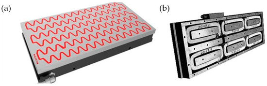
Figure 12.
View of the (a) electromagnetic chuck [36] and (b) the one without a cover [37].
The clamping force generated by electromagnetic clamps (chucks) per 1 cm2 of the clamping surface depends on the design and specifications of the particular electromagnetic clamp in use. There is no universal clamping force value that applies to all electromagnetic clamps, as the force generated can vary significantly based on such factors as the size of the clamp, the strength of the magnetic field, and the current passing through the coil. However, the analysis of catalogue data for various electromagnetic chucks indicates holding forces in the range of 100…150 N/cm2 [36].
The clamping force was also experimentally tested on the same rig as used for the testing of the vacuum clamp, with a steel plate measuring 100 × 150 mm. The obtained average break force equaled 5000 N, resulting in maximum fastening force of 33.3 N/cm2. This value was significantly lower than the catalogue value, due to the intentional use of a thinner yet lighter than recommended steel plate, to avoid oversizing the mass of the entire clamping device.
The masses of electromagnetic chucks are quite high due to the ferromagnetic materials used in their fabrication, as well as the thickness, which for medium-height chucks range from a few centimeters to several centimeters. For example, the type EMU electromagnetic chucks from BRAILLON MAGNETICS SAS [38] have a thickness range from 77 to 90 mm. An analysis of catalogue data for the weight of electromagnetic chucks of different holding areas (ranging from 200 × 600 mm to 600 × 1500 mm) yielded an average electromagnetic chuck mass per 1 cm2 of holding area equal to 0.055 kg/cm2 (results ranged from 0.049 to 0.060 kg/cm2).
The advantages of electromagnetic chucks are as follows:
- Strong holding power: can securely hold ferrous materials due to a strong magnetic field;
- Versatility and controllability: ability to hold different materials, with a control unit for easy activation or deactivation of the magnetic field;
- Adjustable holding force: the magnetic field’s strength can be adjusted to suit specific workpiece requirements;
- A uniform and consistent clamping force across the entire workpiece surface.
The disadvantages of electromagnetic chucks include the following:
- Quite high thickness and mass of the clamp, i.e., a 60 × 60 cm electromagnetic clamp weighs about 200 kg and is about 7–8 cm thick;
- Continuous power requirement: need a constant power supply, with backup necessary to prevent de-clamping during outages;
- Heat generation: prolonged use causes heat buildup in coils, affecting performance;
- Maintenance needs: require cooling and regular maintenance for reliable operation;
- Power and thermal management: careful attention to power and thermal aspects for efficient and safe operation is necessary;
- The cost of purchasing and installing can be relatively high.
4.3. Comparision of Bolt, Vacuum, and Electromagnetic Fastening Methods
To evaluate the potential of different mounting methods, it is necessary to compare their basic characteristics in terms of holding (clamping) force, speed of removal, weight, and cost. The result of comparing the holding forces is presented in Figure 13.
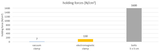
Figure 13.
Comparison of holding forces of vacuum, electromagnetic clamps, and bolts.
Electric car batteries are typically installed in the floors of cars, with low heights ranging from 110 to 180 mm. Given their average density of 2.2 kg per liter, this results in a mass per 1 cm2 of battery ranging from 0.024 to 0.039 kg. This information is crucial when considering the ability of different clamping systems, such as vacuum clamps and electromagnetic chucks, to transfer accelerations to the battery installation. For a vacuum clamp with a holding force of 7 N/cm2, it can transfer accelerations ranging from 20 to 33 g per 1 cm2 of holding area. In contrast, an electromagnetic chuck (for the catalogue value of holding force) can theoretically transfer accelerations in the range of 315 to 516 g (from 84 to 137 g for a thinner steel plate and 33N/cm2 of holding force) per 1 cm2 of holding area.
The comparison of the weight of different fastening systems was realized by comparing the weight of 1 cm2 of fastening surface because it is the main factor affecting the weight of a given holder and its fastening system.
The average material density of an electromagnetic holder is about 3 times greater than that of a vacuum holder, and similarly the height is 3 to 3.5 times greater, resulting in about 10 more mass per 1 cm2. That is why an average electromagnetic chuck mass per 1 cm2 of holding area is equal to 0.055 kg/cm2 and the mass of a vacuum clamp per 1 cm2 of its surface area ranges from 0.005 to 0.008 kg for clamp heights of 20 to 30 mm. For the holding area of 60 × 60 cm this results in a difference of between about 18 to 28 and almost 200 kg. A large mass of electromagnetic clamps requires very powerful electromagnetic vibration exciters or substantially limits the obtainable vibration accelerations or masses of the DUT. The comparison of the weight of different fastening systems is presented in Figure 14.
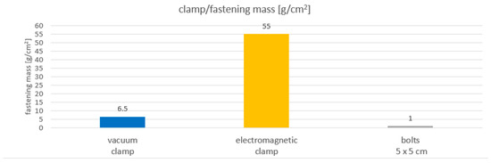
Figure 14.
Comparison of the masses of vacuum, electromagnetic clamps, and bolts.
Looking at the cost of different fastening techniques, it can be said that the cheapest solution are bolts. The price of one hundred of them is about EUR 20. The cost of a 60 × 60 vacuum plate is about EUR 1100, and the cost of three electromagnetic chucks with dimension 20 × 60 cm is about EUR 8500 with additional costs for control units for the electromagnets of around EUR 1000.
A comparison of the disassembly (release) time makes the screws, unrivaled in other parameters, useless for the purpose of creating a system for rapid evacuation of the battery pack under test from the test stand. Pneumatic and electromagnetic mounts allow the DUT to be released from the head expander or the slide table in a matter of seconds, compared to over a dozen minutes for almost 70 bolts.
The performances of the electromagnetic chucks and the vacuum clamping systems in the presence of vibrations can vary, and their suitability depends on the specific requirements of a given application. Due to their strong magnetic holding force, electromagnetic can better transfer vibrations from the base to the workpiece (in this case, the device under test). Vacuum clamping systems can introduce vibration absorption, as the vacuum seal between the workpiece and the table surface can act as a cushion, reducing the transmission of vibrations. In the case of electromagnetic clamps, vibrations can potentially cause wear and tear on electromagnetic chuck components, leading to increased maintenance requirements and a reduced lifespan.
5. Experimental Tests of Vibration Transmissibility of Prototype Non-Standard Mounting Techniques—Materials and Methods
The ENVIBRA Research & Development Group, as a part of the research projectPOIR.01.01.01-00-0814/21—“High fire safety stand for vibration testing of electric vehicle battery modules and full battery packs”, conducted research on the suitability of non-standard fastening techniques in terms of their ability to transmit vibrations.
5.1. Objective of Experimental Studies
The primary objective of experimental tests on prototype mounting techniques of fixtures in vibration tests was to examine their actual function of vibration transmission through the fixture mounted to the headexpander using the tested non-standard mounting techniques, namely vacuum and electromagnetic fastenings. The vibration transmission function is the most crucial property of the fixture and fastening assembly, determining the correctness of the vibration tests. Detailed guidelines regarding the interpretation of transmittance in such studies are provided by the IEC 60068-2 standard [39]. This function should be interpreted as the ratio of vibration acceleration amplitudes between the point of their excitation (shaker armature) and the point of their reading (working surface of the fixture), as follows:
where
H(ω) = (Y (ω))/(X (ω)),
- H(ω)—transmittance in the frequency domain;
- Y (ω)—output signal in the frequency domain—amplitude spectrum of accelerations recorded by a sensor located at selected points on the tested fixtures;
- X (ω)—input signal in the frequency domain—amplitude spectrum of accelerations recorded by a sensor at the point of vibration excitation.
Importantly, the magnitude of H(ω) should be within a well-defined range in order for the vibration test to be performed correctly. The IEC 60068-2-6 defines these tolerances as follows: the compliance of the vertical acceleration amplitudes at the output to the vertical acceleration amplitude at the input should be between 0.75 and 1.25. A value of 1.0 means that the vibration is transmitted without distortion.
5.2. Object under Investigation
In order to obtain information about the actual vibration transmission properties of quick release mountings (fastenings able to be disconnected in times of less than a few seconds) realized by non-standard techniques, the following prototypes were made:
- Vacuum fastening fixtures;
- Electromagnetic clamp fixtures.
To correctly reproduce the operation of the complete system consisting of the headexpander, fixtures, fastening, and the DUT, a laboratory-scale model of the battery pack has been prepared.
5.2.1. Battery Pack Model
For the purposes of the research, it was assumed that the laboratory-scale battery model would have a mass of up to 60 kg and a surface area of 0.6 × 0.6 m. It was possible to adjust the mass of the prepared model (Figure 15) from 10 kg to 60 kg. These values were taken after rescaling the mass of an average battery (approximately 350 kg in size of approximately 2 × 1.5 m) to the laboratory area of 0.6 × 0.6 m.
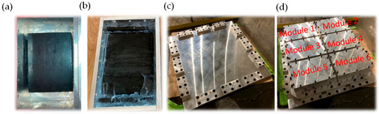
Figure 15.
Laboratory-scale model of the battery pack: (a) single module enclosure with rubber, (b) with rubber and silicone (c) fixture, and (d) fixture with the model of the battery pack.
The traction battery consists of a battery enclosure in which the battery cells or modules are placed. In order to closely mimic the assumed mass density of the modules and, thus, reproduce the dynamic behavior (natural vibrations) correctly, it was decided that its enclosure should be made of 10 mm thick aluminum plates and the volume should be filled with rubber plastic and silicone with a density of 1.1–1.3 kg/dm3 (like the cell filling), as in Figure 15b. Modules (from 2 to 6) were mounted on a single plate which was mounted to the fixture plate (Figure 15c) working with vacuum or electromagnetic fastening.
5.2.2. Electromagnetic Fastening
Figure 16a shows the electromagnetic fastening (green), consisting of two modules generating a magnetic field, attached by bolting to a headexpander made of magnesium alloy (grey). It is a standard commercial electromagnetic chuck from Elmag company, measuring 200 × 600 mm, capable of generating forces of up to 130 N/cm2, according to the manufacturer. The total clamping area is 2400 cm2, so the theoretical clamping force is 312,000 N.

Figure 16.
Electromagnetic chucks: (a) attached to the headexpander, (b) with fixture equipped with steel plate and battery model, and (c) thin steel plate localization.
In order to allow for the correct development of electromagnetic forces, a 3 mm thick steel plate (marked with a red arrow in Figure 16b) was attached under the fixture (orange color) by gluing with methacrylate glue (Figure 16c). A further increase in the thickness of the plate is undesirable, as it increases the weight of the already heavy fixture (90 kg in total). This additional mass significantly reduces the possibility of testing heavier samples or necessitates the purchase of a larger and much more expensive electromagnetic exciter.
Experiments were conducted so that only one component, the fastening, was changed in an excited system consisting of interconnected components. The other components, including the exciter, its head, the headexpander, and the battery sample model, remained unchanged. This makes it possible to conclude positively on the comparability of the tested mounting techniques and to assess the potential of the tested solutions for their implementation on an industrial scale.
5.2.3. Vacuum Fastening
Figure 17a depicts a part of a vacuum fastening device bolted to a head expander. This is a standard Spreitzer vacuum plate with dimensions of 600 × 600 mm. A porous rubber gasket is arranged in the plate’s grooves to maintain the vacuum when the vacuum pump is activated. The maximum vacuum value is approximately 0.83 bar, resulting in a theoretical clamping force of 29,880 N. Figure 17b shows a battery model mounted on the second part of the vacuum fastening system—a flat aluminum plate with fixtures for the battery model, working in conjunction with the Spreitzer vacuum plate.

Figure 17.
The vacuum fastening: (a) bottom part—vacuum plate on the headexpander, (b) complete device with the battery pack model attached to an aluminum plate that is vacuum-sucked onto a vacuum plate.
The relatively low clamping force is a disadvantage of this fastening device, but its advantages include low weight (18 kg) and ease of generating and disabling clamping force (simply turning the vacuum pump on or off).
For comparison, another DUT battery pack model, attached with a standard mounting method—namely, a screw pattern directly connected to the head expander—was also prepared, as shown in Figure 18. Such an arrangement is distinguished by its high rigidity but lacks the function of quick disassembly.
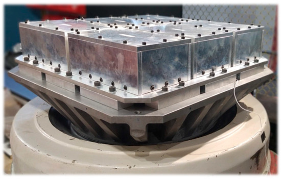
Figure 18.
Battery sample model bolted directly to the LDS V850 vibration system.
5.3. Scope of Tests and Measurement Equipment
In order to reproduce the actual operating conditions of the fastening devices, the tests were carried out under various conditions derived from the standards for battery pack testing. With reference to these standards, the following test parameters were selected: vertical vibration direction, sweeping with a sinusoidal signal from 5 to 200 Hz and return from 200 Hz to 5 Hz at a rate of 3 octaves per minute, and amplitudes from 10 m/s2 to 80 m/s2 for a maximum mass of 60 kg.
The following measuring apparatus and tools were used during the tests:
- An LDS V850 (Ling Dynamic Systems, Roystone, UK) exciter with a 440 mm head and 600 mm square headexpander, having a first natural frequency of 950 Hz with a UD APEX vibration exciter controller (Unholtz Dickie Corporation, Wallingford, CT, USA);
- A Dewesoft Sirius data acquisition system working with DewesoftX data recording and analysis software (Dewesoft d.o.o., Trbovlje, Slovenia);
- An Endevco 256HX-100 single-axis acceleration transducer (exciter control sensor), (Meggitt Sensing System, Irvine, CA, USA);
- An Endevco 751-100 uniaxial acceleration transducer (sensor No. 1) (Meggitt Sensing System, Irvine, CA, USA);
- A Dytran 3055D2 uniaxial acceleration transducer (sensor No. 2) (Dytran Instrument, Chatsworth, CA, USA);
- A Dytran 63C13 triaxial acceleration transducer (sensor No. 3) (Dytran Instrument, Chatsworth, CA, USA);
- A Dytran 3133A1 triaxial acceleration transducer (sensor No. 4) (Dytran Instrument, Chatsworth, CA, USA).
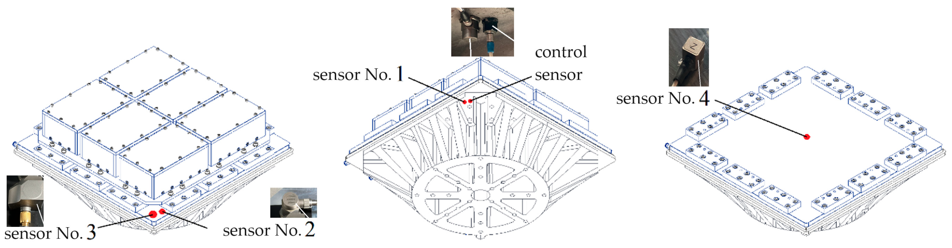
The head control sensor (necessary for the vibration exciter controller) was attached to the undersurface of the headexpander. Next to the control sensor, there was sensor No. 1, which was treated as an input sensor for transmittance determination. Two output sensors, No. 2 and No. 3, were mounted on the corner of the flat aluminum plate, the second part of the vacuum fastening device. In addition, output sensor No. 4 was placed in the center of the flat aluminum plate under the sample. No signal was measured directly on the sample, as the purpose of the tests was to check the ability of the various fastening devices to transmit the specified accelerations. But the DUT battery pack model allowed an additional component to be introduced into the dynamics of the whole system, making the tests more meaningful. The arrangement of the vibration sensors fixed with glass-drying adhesive is shown in Figure 19.
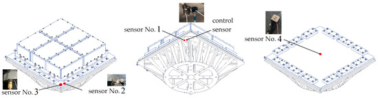
Figure 19.
The arrangement of vibration sensors during vertical vibration testing.
5.4. Measurement Data Processing
As previously mentioned, the Dewesoft Sirius data acquisition system was used for data acquisition, working with DewesoftX data recording and analysis software. This software was used for visualizing the transmittance function using two-dimensional plots, where the frequency is displayed on the y-axis in Hz and the gain is displayed on the x-axis (dimensionless value). The procedure for determining the transfer function curves proceeded in the following steps:
- Transformation of the signal from the time domain to the frequency domain via Fourier transform, as follows:where is any time function called the original function, and is a complex variable; the Dewesoft software allows for the selection of the windowing method, spectrum resolution, and preliminary low-pass filtering; Blackman windowing was chosen, with a resolution of 1.6 Hz and a cutoff frequency of 2000 Hz; the procedure was implemented for both the output and input signals.
- Determination of the ratio of the output and input signals in the frequency domain, thereby establishing the gain value as a dimensionless quantity.
- Plotting the charts of transmissibility.
6. Experimental Tests of Vibration Transmissibility of Prototype Non-Standard Mounting Techniques—Results
6.1. Electromagnetic Fastening
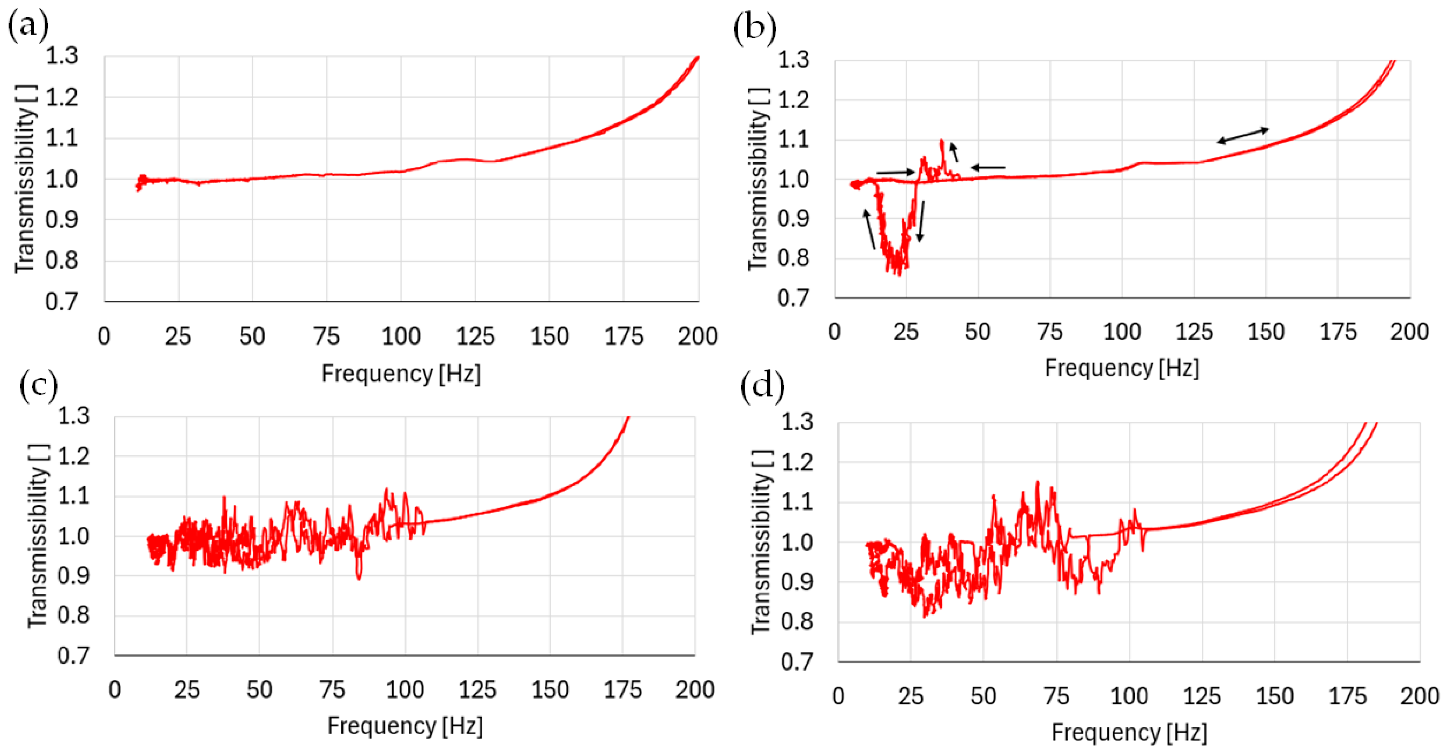
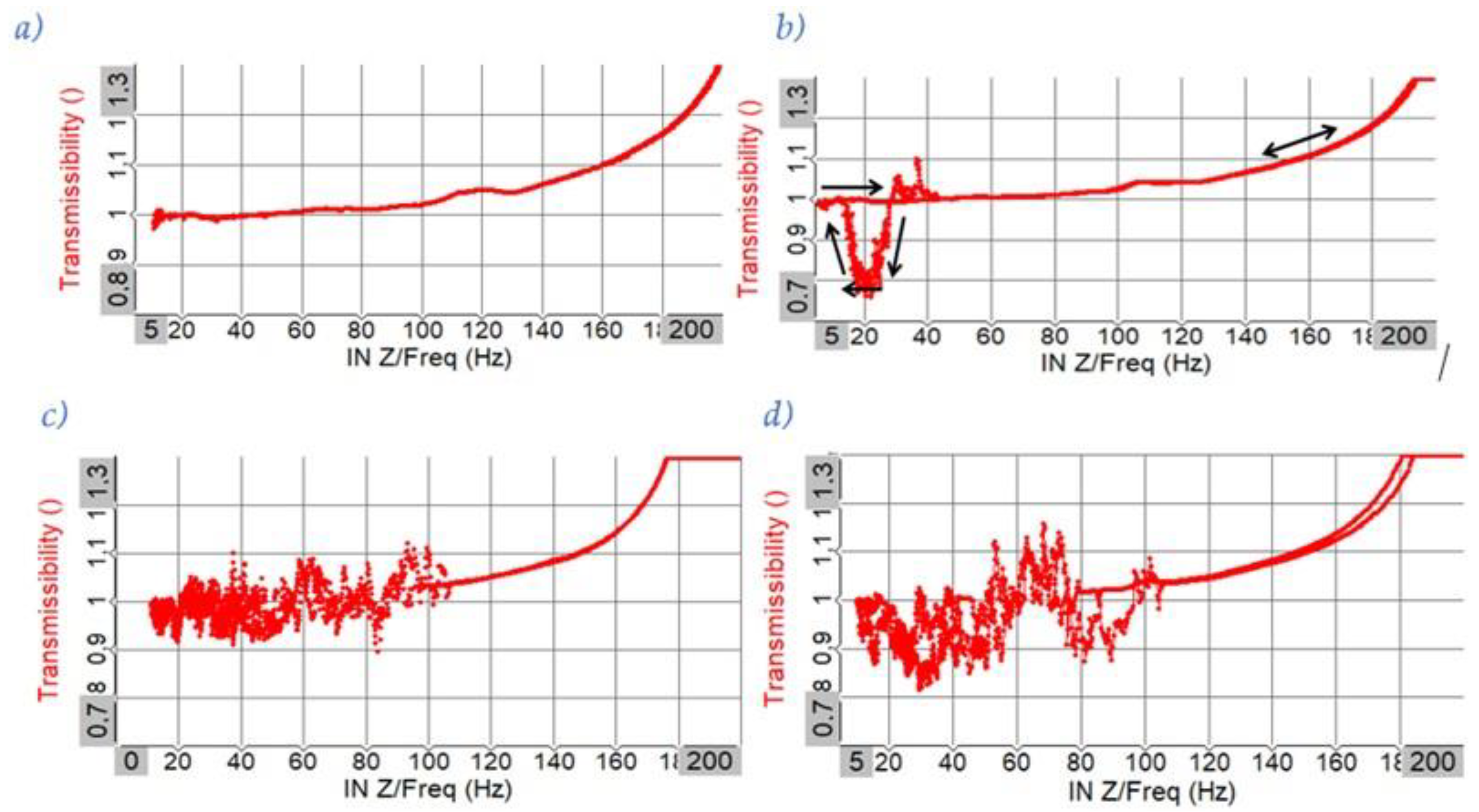
In the charts presented in Figure 20, the results of the experimentally obtained transmittance functions for the electromagnetic chuck at measurement point 2 are presented. The ordinate axis represents transmittance as a dimensionless quantity, and the abscissa axis represents the frequency in Hz.
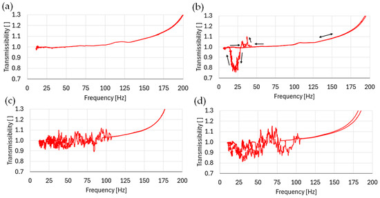
Figure 20.
Transmittance function for the electromagnetic chuck in the frequency domain for sensor no. 2: (a) test 1 g, (b) test 2 g, (c) test 4 g, and (d) test 8 g.
The determined transfer function functions show clear deviations from the requirements of the industry standard IEC 60068-2-6. In each case, the transmittance increases with frequency. Graph 20 (a) illustrates the changes in transmittance for acceleration equal to 1 g. Under these conditions, the transmittance changes in a predictable manner—it increases non-linearly. The situation is different for higher acceleration amplitudes. It was observed that it changes randomly and unpredictably without a trend in the low frequency range (up to 100 Hz). It was hypothesized that the cause of such a transfer function curve was the detachment of the sample from the holder due to insufficient holding force.
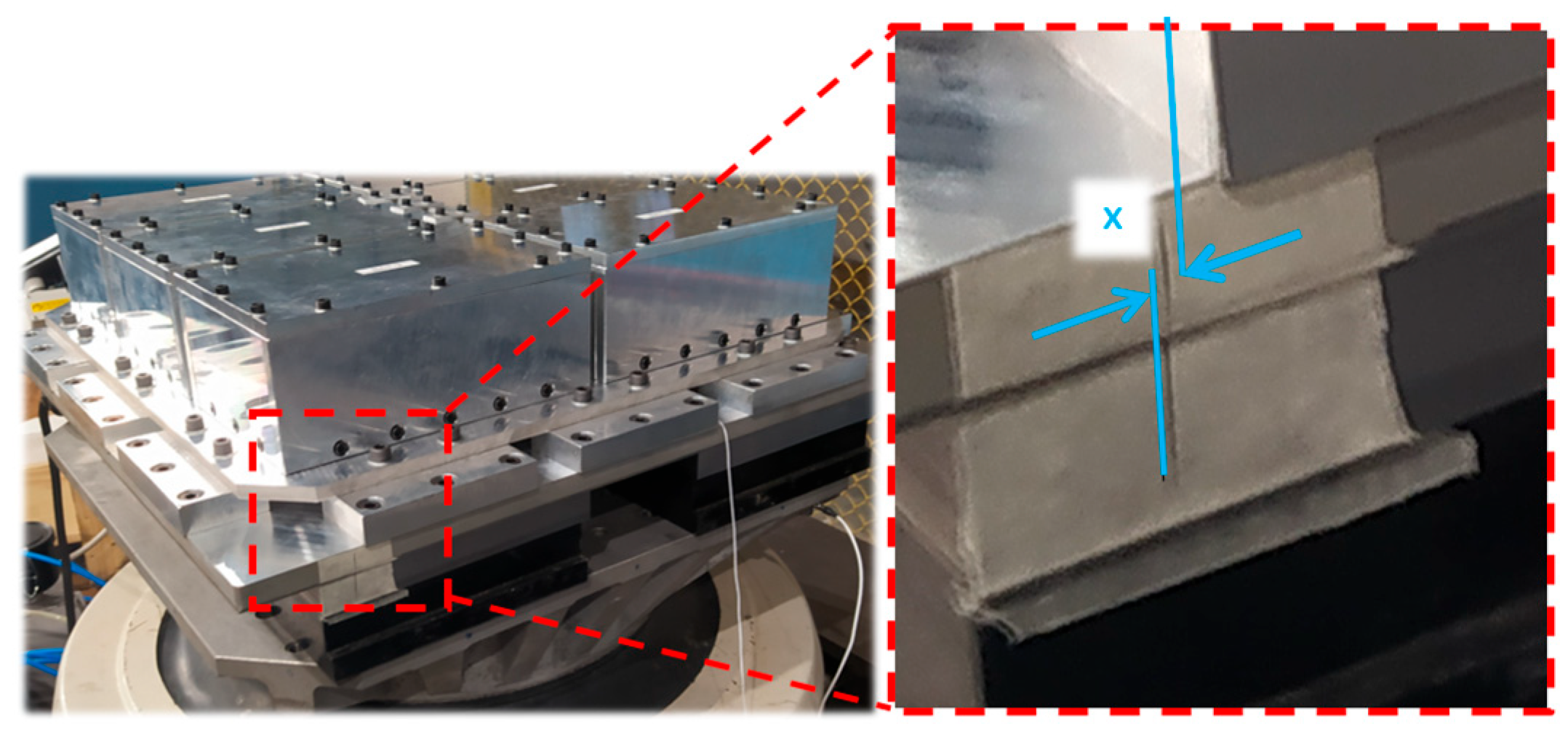
To confirm this assumption, an additional experiment was prepared (Figure 21). Paper tape was attached to the side surfaces of the holder. Before the vibrational experiment commenced, a line was drawn so that the dimension “×” from the drawing in Figure 21 was equal to 0. After conducting vibrational studies, a displacement of 2–3 mm was observed. Thus, the assumption was confirmed. This means, at the same time, that the electromagnetic holder in the presented configuration should not be used for vibrational tests.
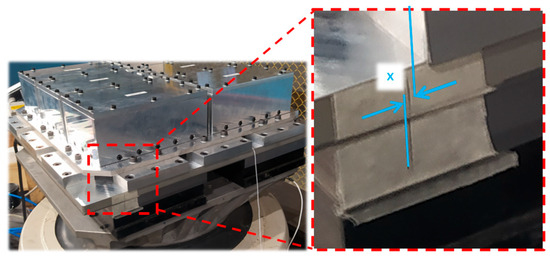
Figure 21.
View of paper tape with a mark indicating the susceptibility of the clamp to detaching during vibration.
A hypothesis was proposed that the steel plate placed under the holder was too thin. This prevented the proper development of the electromagnetic field and the generation of the desired clamping forces. Further increasing the thickness of the steel plate has an exceptionally adverse effect on the mass balance of an already heavy holder. Increasing the mass necessitates the installation of an exciter with a greater dynamic force, which in turn significantly affects investment, service, and operating costs. Additional research work is required in this area.
6.2. Vacuum Fastening
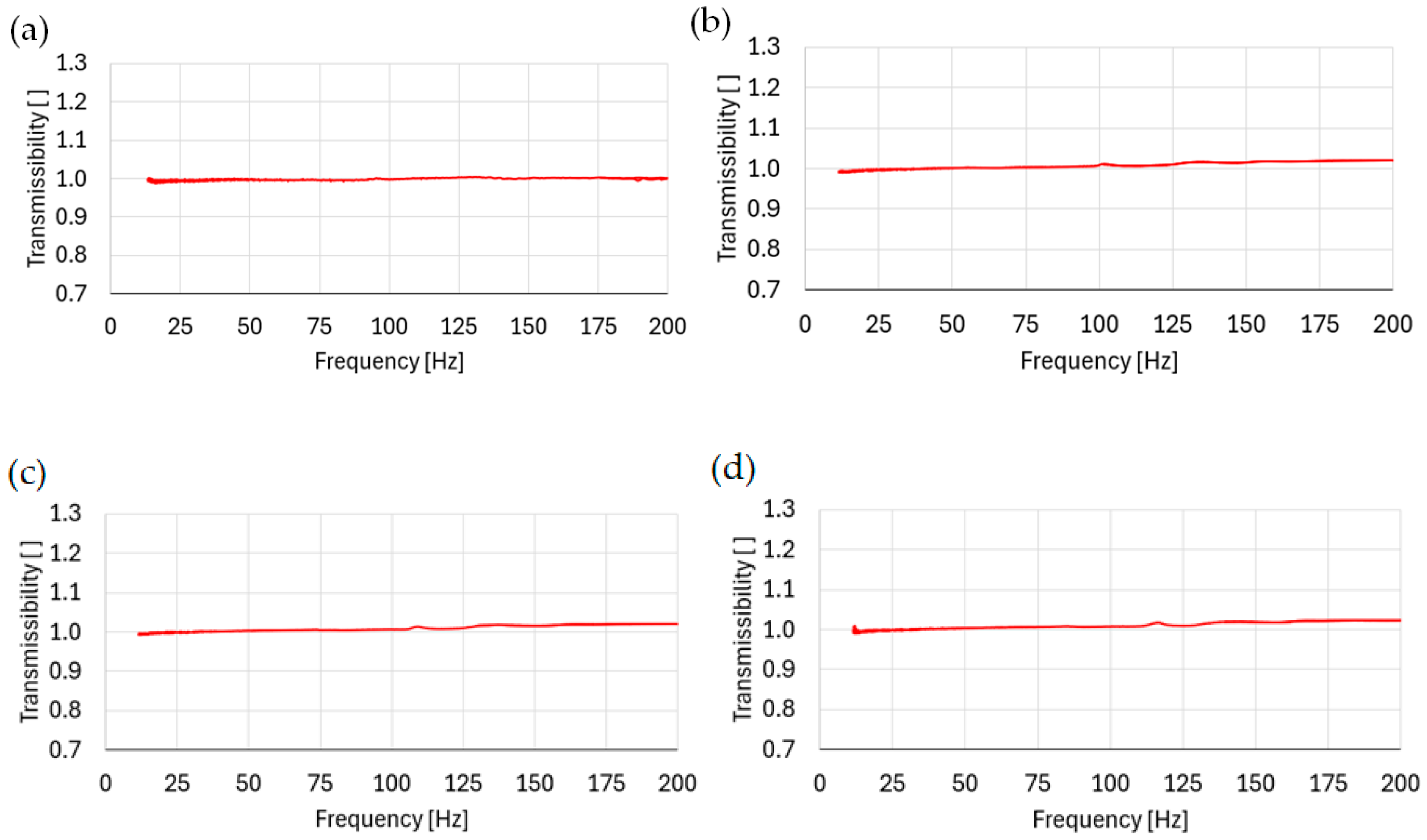
The charts in Figure 22 present the results of the experiments of the transmittance function for the vacuum clamp at measurement point 2. The ordinate axis represents transmittance as a dimensionless quantity, and the abscissa axis represents frequency in Hz. The results of the transmissibility function are much better aligned with the standard compared to electromagnetic clamp showing an almost straight line. The vacuum clamps for 1 g, 2 g, 4 g, and 8 g amplitudes of acceleration meet the requirements of the IEC 60068-2-6 standard.

Figure 22.
Transmittance function for the vacuum clamp in the frequency domain for sensor no. 2: (a) test 1 g, (b) test 2 g, (c) test 4 g, and (d) test 8 g.
6.3. Standard Mounting Method—Screw Pattern
The charts presented in Figure 23 present the results of experiments of the transmittance function for the standard mounting method, i.e., the screw pattern, at measurement point 2.
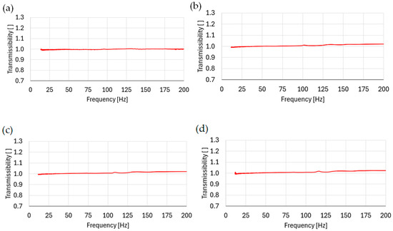
Figure 23.
Transmittance function for the standard mounting method, i.e., the screw pattern in the frequency domain for sensor no. 2: (a) test 1 g, (b) test 2 g, (c) test 4 g, and (d) test 8 g.
The ordinate axis represents transmittance as a dimensionless quantity, and the abscissa axis represents frequency in Hz. Straight lines representing transmittance were observed for the entire investigation spectrum.
The differences in the peak value of the transmittance function for the vacuum holder (Figure 22) and a screw connection system (Figure 23) result from the different designs of the two fixtures, as well as their different stiffnesses and mass distributions. The fact that the vacuum mount has a higher amplitude amplification than the screw mounting indicates a poorer ability to transmit vibrations without alterations. Nevertheless, for the operating conditions presented, both solutions meet the normative requirements.
6.4. Comparison of Transmittance Functions of Tested Fastening Methods
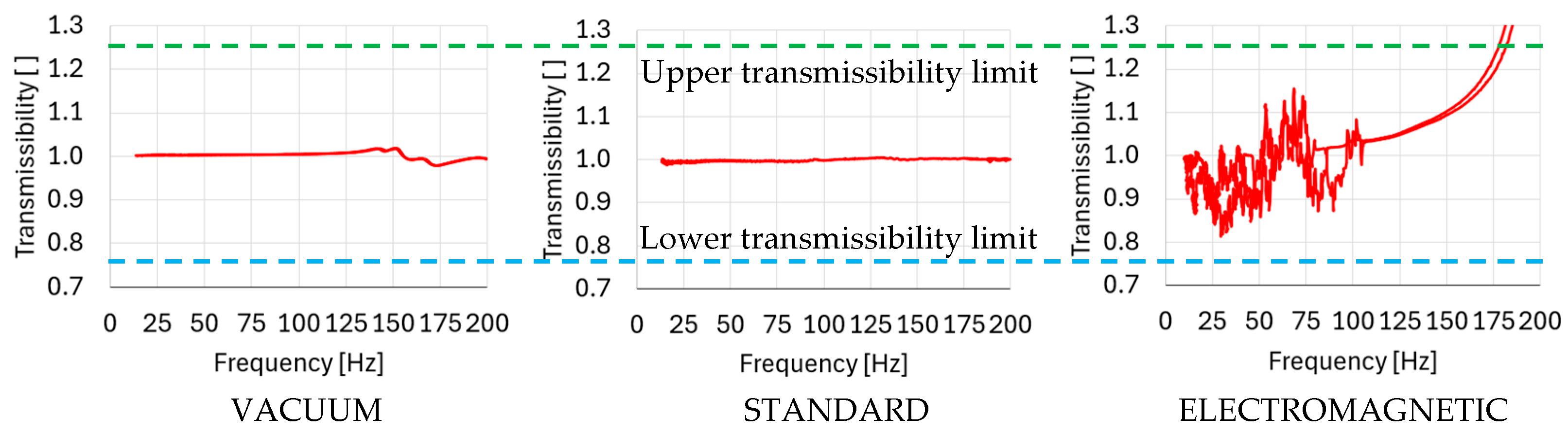
The conducted experimental studies on the transmittance of various mounting techniques have shown that bolted connections are characterized by the most favorable transmittance function profile—throughout the entire examined range of 0–200 Hz, an almost constant value was observed. Slightly worse results, with deviations of about 2–3% from the constant value, were obtained for the vacuum chuck, which demonstrates its significant potential for use as a mounting technique with the possibility of rapid disassembly in vibration studies. A comparison of the transfer functions for the presented mounting techniques is illustrated in Figure 24.
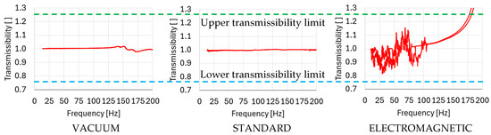
Figure 24.
Comparison of transfer functions for the presented boundary conditions.
For the electromagnetic chuck, the obtained results disqualified the tested prototype from applications in vibration studies. The transmittance function exceeded the threshold level (1.25) already at around 170 Hz, and as the frequency increased, it grew at a very rapid pace, multiplying the amplitudes of the induced vibrations. The cause of this situation could presumably be due to the following two factors:
- 1.
- Resonance of internal structures in the electromagnetic chuck. There is a coil embedded in a soft material inside, which may induce such adverse effects;
- 2.
- Insufficient thickness of a ferromagnetic material plate (3 mm steel sheet) that was used trying to avoid an excessive weight increase in the prototype electromagnetic chuck, which, however, prevented the proper development of electromagnetic forces.
7. Conclusions
The theoretical analysis and experiments carried out highlighted the important role of DUT fastenings and fixtures in vibration testing. It was shown that they must be characterized by various, often contradictory features, of which, however, the most important are those that ensure the functional correctness of the tests carried out—the ability to transmit vibrations from the headexpander to the DUT with as little alteration as possible over the entire range of vibration amplitudes and accelerations used in the tests. A comparison of features of investigated fastening techniques is shortly presented in Table 1 and described in the further part of the conclusion.

Table 1.
A comparison of features of investigated fastening techniques.
The theoretical analysis showed that the commonly used bolted fastenings are difficult to replace due to their unbeatable clamping forces, weight, and cost. The only problem is the assembly and disassembly time of the multiple bolted connections, which is crucial for the concept of rapid evacuation of a battery under fire from the test site. This drawback persuaded the authors to carry out a theoretical analysis and experimental tests to assess the potential of using non-standard mounting techniques, i.e., vacuum and electromagnetic fixtures, with quick and automated release capabilities.
The analyses and tests carried out showed that the range of fastening forces is much smaller for the proposed non-standard methods, at only about 7…8 N/cm2 of area for vacuum clamping and from about 33 to 100…130 N/cm2 of area for electromagnetic clamping, compared with values in the order of 1600 N/cm2 for the bolted fastenings.
Furthermore, when comparing the mounting devices’ weights, the screw pattern at 1 g/cm2 per clamp surface area is unrivalled against the 6.5 g/cm2 and 55 g/cm2 of the vacuum and electromagnetic clamp surface areas, respectively.
The final test, however, was meant to test the transmittance of the prototype implementations of the vacuum and electromagnetic mounting techniques. As a result of the tests, the electromagnetic fastening was disqualified, as it quickly lost the ability to transmit vibrations to the fixture as required by the standard (transmittance differing from one by no more than ±25%). An additional major disadvantage was its very high weight.
In contrast, in the frequency range investigated in the tests (up to 200 Hz), vacuum clamping remained within the boundaries defined in the standard, showing a potential for use in vibration tests. Its transmittance in this frequency range differed by no more than 3%. At the same time, the relatively low mass of the fixture has the potential for further reduction through the possibility of integrating the lower part of the fixture with the headexpander and the upper part with the fixture.
These results show that even if the holding forces of vacuum clamping may be considerably lower, they can still be adequate for transmitting vibrations with necessary amplitudes.
The implementation of alternative clamping methods, such as vacuum clamping, could significantly enhance the efficiency and safety of electric vehicle battery vibration testing. This research contributes to the field of vibration testing and also has broader implications for safety and efficiency in the rapidly evolving domain of electric vehicle technology.
Author Contributions
Conceptualization, G.Ś. and M.S.; methodology, G.Ś. and M.S.; software, M.S.; formal analysis, G.Ś.; investigation, G.Ś., M.S. and J.M.; resources W.K.; data curation, M.S. and J.M.; writing—original draft preparation, G.Ś. and M.S.; writing—review and editing, G.Ś., M.S. and J.M.; visualization, M.S. and J.M.; supervision, G.Ś. and M.S.; project administration, W.K. and M.S.; funding acquisition, W.K. and M.S. All authors have read and agreed to the published version of the manuscript.
Funding
The research was carried out under the project POIR.01.01.01-00-0814/21—“High fire safety stand for vibration testing of electric vehicle battery modules and full battery packs” co-financed by the European Union from the European Regional Development Fund under the Intelligent Development Program. The project is implemented under the competition of the National Centre for Research and Development: Fast Track. 
Institutional Review Board Statement
Not applicable.
Informed Consent Statement
Not applicable.
Data Availability Statement
The data presented in this study are available within the article.
Conflicts of Interest
The authors declare no conflicts of interest.
References
- Yoshio, N. Lithium ion secondary batteries; past 10yearsandthefuture. J. Power Sources 2001, 100, 101–106. [Google Scholar]
- Global EV Sales for 2023H1. Available online: https://www.ev-volumes.com/news/global-ev-sales-for-2023-h1/ (accessed on 8 January 2024).
- IEA. Electric Car Sales, 2016–2023, IEA, Paris. Licence: CCBY4.0. Available online: https://www.iea.org/data-and-statistics/charts/electric-car-sales-2016-2023 (accessed on 8 January 2024).
- Shashank, A.; Shen, W.; Ajay, K. Review of mechanical design and strategic placement technique of a robust battery pack for electric vehicles. Renew. Sustain. Energy Rev. 2016, 60, 1319–1331. [Google Scholar]
- Zwicker, M.F.R.; Moghadam, M.; Zhang, W.; Nielsen, C.V. Automotive battery pack manufacturing—Are view of battery to tab joining. J. Adv. Join. Process. 2020, 1, 100017. [Google Scholar] [CrossRef]
- Ruiz, A.; Phrang, A.; Omar, N.; Van Den Bossche, P.; Kriston, A.; Boon-Brett, L. Are view of international abuse testing standards and regulations for lithium ion batteries in electric and hybrid electric vehicles. Renew. Sustain. Energy Rev. 2017, 81, 1427–1452. [Google Scholar] [CrossRef]
- Lai, X.; Yao, J.; Jin, C.; Feng, X.; Wang, H.; Xu, C.; Zheng, Y.A. Review of Lithium-Ion Battery Failure Hazards: Test Standards, Accident Analysis, and Safety Suggestions. Batteries 2022, 8, 248. [Google Scholar] [CrossRef]
- Li, J.; Wang, J.; Xie, J.; Jiang, J. Risk assessment of lithium-ion battery road transportation using the data-driven Bayesian network considering battery self-heating. Process Saf. Environ. Prot. 2023, 175, 715–731. [Google Scholar] [CrossRef]
- Feng, X.; Ouyang, M.; Liu, X.; Lu, L.; Xia, Y.; He, X. Thermal runaway mechanism of lithium ion battery for electric vehicles: Are view. Energy Storage Mater. 2018, 10, 246–267. [Google Scholar] [CrossRef]
- Chombo, P.V.; Laoonual, Y.; Wongwises, S. Lessons from the Electric Vehicle Crashworthiness Leading to Battery Fire. Energies 2021, 14, 4802. [Google Scholar] [CrossRef]
- Chen, Y.; Kang, Y.; Zhao, Y.; Wang, L.; Liu, J.; Li, Y.; Liang, Z.; He, X.; Li, X.; Tavajohi, N.; et al. A review of lithium-ion battery safety concerns: The issues, strategies, and testing standards. J. Energy Chem. 2021, 59, 83–99. [Google Scholar] [CrossRef]
- UN. 38.3 Rev.7, Recommendations on the Transport of Dangerous Goods; Manual of Tests and Criteria; UN: New York, NY, USA; Geneva, Switzerland, 2019. [Google Scholar]
- UN/ECE. Regulation No. 100.02. Uniform Provisions Concerning the Approval of Vehicles with Regard to Specific Requirements for the Electric Power Train; UNECE: Geneva, Switzerland, 2013. [Google Scholar]
- UL 2580; Batteries for Use in Electric Vehicles. UL Standard: Northbrook, IL, USA, 2013.
- SAE J2464; Electric and Hybrid Electric Vehicle Rechargeable Energy Storage System (RESS) Safety and Abuse Testing. Society of Automotive Engineers: Pittsburgh, PA, USA, 2021.
- ISO 12405-4:2018; Electrically Propelled Road Vehicles—Test Specification for Lithium-Ion Traction Battery Packs and Systems Part 4: Performance Testing. ISO: Geneva, Switzerland, 2018.
- Li, H.; Peng, W.; Yang, X.; Chen, H.; Sun, J.; Wang, Q. Full-Scale Experimental Study on the Combustion Behavior of Lithium-Ion Battery Pack Used for Electric Vehicle. Fire Technol. 2020, 56, 2545–2564. [Google Scholar] [CrossRef]
- Sun, P.; Bisschop, R.; Niu, H.; Huang, X. A Review of Battery Fires in Electric Vehicles. Fire Technol. 2020, 56, 1361–1410. [Google Scholar] [CrossRef]
- Kukreja, J.; Nguyen, T.; Siegmund, T.; Chen, W.; Tsutsui, W.; Balakrishnan, K.; Liao, H.; Parab, N. Crash analysis of a conceptual electric vehicle with a damage-tolerant battery pack. Extrem. Mech. Lett. 2016, 9, 371–378. [Google Scholar] [CrossRef]
- Electric Vehicle Battery Testing. Available online: https://www.dataphysics.com/applications/shaker-testing-and-vibration-control/automotive-vibration-testing/electric-vehicle-battery-testing/ (accessed on 8 January 2024).
- Ghiji, M.; Novozhilov, V.; Moinuddin, K.; Joseph, P.; Burch, I.; Suendermann, B.; Gamble, G. A Review of Lithium-Ion Battery Fire Suppression. Energies 2020, 13, 5117. [Google Scholar] [CrossRef]
- Kovachev, G.; Ellersdorfer, C.; Gstrein, G.; Hanzu, I.; Wilkening, H.M.R.; Werling, T.; Schauwecker, F.; Sinz, W. Safety assessment of electrically cycled cells at high temperatures under mechanical crush loads. E-transportation 2020, 6, 100087. [Google Scholar] [CrossRef]
- Lang, J.F.; Kjell, G. Comparing vibration measurements in an electric vehicle with standard vibration requirements for Li-ion batteries using power spectral density analysis. Int. J. Electr. Hybrid Veh. 2015, 7, 272–286. [Google Scholar] [CrossRef]
- IEC 60068-2-64; Environmental Testing—Part 2-64: Tests—Test Fh: Vibration, Broadband Random and Guidance. IEC: Geneva, Switzerland, 2008.
- SAE J2380_202112; Vibration Testing of Electric Vehicle Batteries. Society of Automotive Engineers: Pittsburgh, PA, USA, 2021.
- McConnell, K.G.; Varoto, P.S. Vibration Testing Theory and Practice, 2nd ed.; John Wiley & Sons: Hoboken, NJ, USA, 2008. [Google Scholar]
- An Introduction to Sentek Dynamics Vibration Testing Systems. Available online: https://www.sentekdynamics.com/s/Introduction-to-Sentek-Dynamics-Vibration-Testing-Systems.pdf (accessed on 10 January 2024).
- Barros, E.D.; Souto, C.D. Evaluation of a Vibration Test Fixture. Int. J. Acoust. Vib. 2017, 22, 348–352. [Google Scholar]
- Automotive Vibration Testing, Applied Technical Services. Available online: https://atslab.com/automotive-testing/automotive-vibration-testing/ (accessed on 28 January 2024).
- Raut, S.S.; Madgulkar, N.A.; Sathe, S.A.; Wadkar, S.P.; Sathe, T. Study of Vibration Fixtures. Int. J. Curr. Eng. Technol. 2017, 7, 75–77. [Google Scholar]
- Custom Vibration Testing Fixtures. Available online: https://paragonsystems.net/testing-services/vibration-fixtures-manufacturer/ (accessed on 29 January 2024).
- Toggle Clamps. Available online: https://www.halderusa.com/PM/Standard-Parts/Clamping-Elements/Toggle-Clamps (accessed on 27 January 2024).
- Clamping Fixture. Available online: https://www.vibsource.com/quick-clamping-fixture.html (accessed on 27 January 2024).
- EP4080187(A1)—Accessory Plate, Fixture and Machine for Vibration-Tests. Available online: https://pl.espacenet.com/publicationDetails/biblio?II=0&ND=3&adjacent=true&locale=pl_PL&FT=D&date=20221026&CC=EP&NR=4080187A1&KC=A1# (accessed on 27 January 2024).
- Vacuum Clamping Devices. Available online: http://www.boehm-feinmechanik.com/html/vacuum_clamping_devices.html (accessed on 24 January 2024).
- ElmagWave Electromagnetic Chuck for Surface Grinding. Available online: https://eshop.walmagmagnetics.com/Manufacturer/en-US/47/elmag-wave-electromagnetic-chuck (accessed on 28 January 2024).
- Magnetoool Inc.—Repair Facilities. Available online: https://www.magnetoolinc.com/products/repair-facilities/ (accessed on 25 January 2024).
- Electromagnetic and Electropermanent Magnetic Chucks–Grinding. Available online: https://pl.braillon.com/electromagnetic-and-electropermanent-magnetic-chucks-grinding.html (accessed on 28 January 2024).
- IEC 60068-2-6; Environmental Testing—Part 2–6: Tests—Test Fc: Vibration (Sinusoidal). IEC: Geneva, Switzerland, 2007.


Disclaimer/Publisher’s Note: The statements, opinions and data contained in all publications are solely those of the individual author(s) and contributor(s) and not of MDPI and/or the editor(s). MDPI and/or the editor(s) disclaim responsibility for any injury to people or property resulting from any ideas, methods, instructions or products referred to in the content. |
© 2024 by the authors. Licensee MDPI, Basel, Switzerland. This article is an open access article distributed under the terms and conditions of the Creative Commons Attribution (CC BY) license (https://creativecommons.org/licenses/by/4.0/).