Article

Multi-Material Optimization for Lattice Materials Based on Nash Equilibrium

School of Aeronautic Science and Engineering, Beihang University, 37 Xueyuan Road, Beijing 100191, China
*
Author to whom correspondence should be addressed.
Appl. Sci. 2024, 14(7), 2934; https://doi.org/10.3390/app14072934
Submission received: 29 February 2024 / Revised: 26 March 2024 / Accepted: 27 March 2024 / Published: 30 March 2024
(This article belongs to the Section Additive Manufacturing Technologies)

Abstract

:
Lattice materials are regarded as a new family of promising materials with high specific strength and low density. However, in the optimization of lattice materials, it is difficult in general to determine the material distribution in lattice structures due to the complex optimization formulations and overlaps between different materials. Thus, the article proposes to use the Nash equilibrium to address the multi-material optimization problem. Moreover, a suppression formula is investigated to tackle the issue of material overlapping. The proposed method is validated using a cantilever beam example, showing superior optimization results compared to single-material methods, with a maximum improvement of 20.5%. Moreover, the feasibility and stability of the approach are evaluated through L-shaped beam examples, demonstrating its capability to effectively allocate materials based on their properties and associated stress conditions within the design. Additionally, an MBB test demonstrates superior stiffness in the proposed optimized specimen compared to the unoptimized one.

1. Introduction

Lattice materials [1], characterized by high porosity and periodicity, have attracted great interest in the field of structural light weight [2,3]. In addition to their excellent mechanical properties, they also have functional properties such as energy absorption [4] and thermal applications [5,6]. So they are widely used in fields such as the automotive industry [7], aerospace industry [8,9], biomedical industry [10], etc. Recently, with the advancement in additive manufacturing (AM) technology [11], effective manufacturing methods for lattice materials with complex geometric shapes have emerged. Consequently, research on the configuration of lattice materials at the mesoscale and the design of topological configurations at the macroscale have garnered significant attention from scholars.
Unlike conventional materials, the performance of lattice materials at the macroscale depends on the topologies and size of the unit cell inside the lattice at the mesoscale [12]. This implies that different geometry units have different mechanical properties. Therefore, in order to obtain better stiffness of the lattice structure, scholars have deepened the research on the mechanical properties of lattice materials.
Due to the large amount of mesoscopic topologies [13] inside the lattice materials, direct structural modeling and analysis would result in a huge workload, and universal finite element methods are no longer applicable. Equivalent computation approaches, such as the representative volume element (RVE) method [14] and homogenization method [15], have been proposed to reduce computational costs. Yan [16] compared the prediction results of the equivalent properties of lattice materials with periodic mesostructures using these two methods. Zhang et al. [17] proposed the extended multiscale finite element method (EMsFEM). This method not only takes into account the absolute size of the mesostructure of lattice materials but also enables easy implementation. It can optimize the design of lattice materials for complex engineering structures with practical shapes, loads, and boundaries. Furthermore, there have been efforts by scholars to employ particle-based methods, such as the Elastic Network Model [18], Molecular Dynamics [19] and Monte Carlo [20], in order to predict the mechanical characteristics of lattice materials. This approach involves treating the nodes of the lattice as individual particles and analyzing the material’s properties by simulating the interactions between these particles. Such a method is particularly well suited for investigating the mesostructure and localized properties of materials.
Assisted by methods for calculating the equivalent properties of lattice materials, we can delve deeper into the design of lattice materials to explore their performance, enabling the feasibility of multi-material optimization for lattice materials.
Topology optimization is a technique that enables the rational distribution of materials within a specific design domain, based on specific boundary conditions and constraints [15]. For over thirty years, different topology optimization methods [21,22,23,24] have been proposed. However, most studies focused on single-material optimization. In some specialized fields where there are higher requirements for structural materials, single-material solutions cannot meet the usage demands. As a result, multi-material optimization has garnered widespread attention. Therefore, there is considerable interest in developing topology optimization methods for multi-material structures. Compared to optimizing single-material structures, optimizing multi-material structures presents greater challenges. Firstly, a reasonable optimization formulation is needed to effectively represent different materials within the design domain while also facilitating sensitivity analysis. Additionally, it is necessary to add appropriate constraints to prevent overlap between different materials, ensuring that the final optimization result aligns with subsequent manufacturing requirements.
Currently, in the field of multi-material optimization research, the most widely studied method is the topology optimization method for multi-material composite structures based on SIMP (Solid Isotropic Material with Penalization). Bendsøe and Sigmund [15] combined SIMP with the Voigt bound, H-S bound, and R-V material interpolation methods to address multi-material topology optimization problems. Meanwhile, Sigmund [25] also proposed a mixed material interpolation method for the topology design of multi-physics compliant mechanisms. This method is based on the SIMP interpolation method to interpolate solid and empty materials, and the H-S upper and lower boundary weight method to interpolate solid materials. However, due to the large number of design variables involved in this optimization method, the optimization solution process is slow. When studying the optimization problem of composite materials, Stegmann and Lund [26] proposed a Discrete Material Optimization (DMO) method, which utilizes gradient information and mathematical programming to solve discrete optimization problems. Here, the equivalent material properties of the unit are obtained as the linear weighted average values of each material property. The advantage of this multi-material interpolation method lies in the gradual decrease in weight coefficients corresponding to other design variables as the value of a particular design variable increases. Meanwhile, Zhou and Wang [27] described an optimization method based on the phase field approach, using a generalized Cahn–Hilliard model to address the topological optimization of multi-material structures. Due to its straightforward concept and ease of differentiation, this multi-material interpolation method is also widely applied for material interpolation in topology optimization problems of multi-material composite structures. Hvejse and Lund [28] extended the SIMP and Rational Approximation of Material Properties (RAMP) interpolation models for two-phase materials, thereby providing two material interpolation models that can be applied to interpolate any number of materials. Tajs-Zielińska and Bochenek [29] introduced an efficient heuristic topology generator for the topology optimization of graded multi-material structures. This method does not necessitate gradient calculation and is straightforward to implement numerically. Zheng et al. [30] extended a Matlab code for multi-material topology optimization on the classic 88-line code [31] and made the code openly available for scholars to facilitate learning and the exchange of ideas.
While several methods have been discussed above, game theory can also be applied to address the allocation of different materials within the design domain in multi-material optimization. Game theory, a branch of applied mathematics, serves as an analytical tool for making optimal choices in decision-making problems. In structural optimization, the goal is to find the best solution within a limited set of options. From a certain standpoint, it can be argued that game theory essentially functions as an optimization method. Sohrabi and Karim [32] summarized research that combines game theory and optimization algorithms, highlighting the close correlation between game theory and optimization concepts. Many studies utilize their combinations to address a wide array of problems. Greiner et al. [33] listed the applications of evolutionary algorithms based on game theory in structural optimization and skeletal structures. Additionally, the Nash evolutionary algorithm demonstrates superior performance compared to other algorithms in terms of convergence speed and optimization effectiveness when addressing structural problems such as the reconstruction inverse problem (RIP) [34], fully stressed design (FSD) [35], and minimum constrained weight (MCW) [36].
Currently, Nash game theory has found widespread applications in the field of multi-objective and multidisciplinary optimization problems. Holmberg et al. [37] used generalized Nash equilibrium to solve topology optimization with uncertain loading; applying the game theory framework they proposed allows for the formulation of a wide range of related structural optimization problems. Hubbal et al. [38] explored a multidisciplinary topology optimization design problem under thermal–structural coupling using Nash game theory. Périaux et al. [39] used game theory and genetic algorithms for the shape optimization of a nozzle. Desideri [40] applied game theory to aero-structural aircraft wing shape optimization.
In this paper, we propose to use the Nash equilibrium [41] to solve the material distribution problem brought about in the design of lattice materials at the mesoscale. In Section 2, we introduce an EMsFEM for solving the equivalent mechanical properties of lattice materials. In Section 3, we briefly introduce the Nash equilibrium theory and propose multi-material optimization formulations based on Nash equilibrium. Meanwhile, we address the problem of material overlap through a suppression formula. In Section 4, we validate this method’s superior optimization effect by compare it with the results of the single-material optimization method and a L-shaped beam examples conducted to validate feasibility of the method. Finally, we utilize 3D-printing technology to produce the specimens for tests.

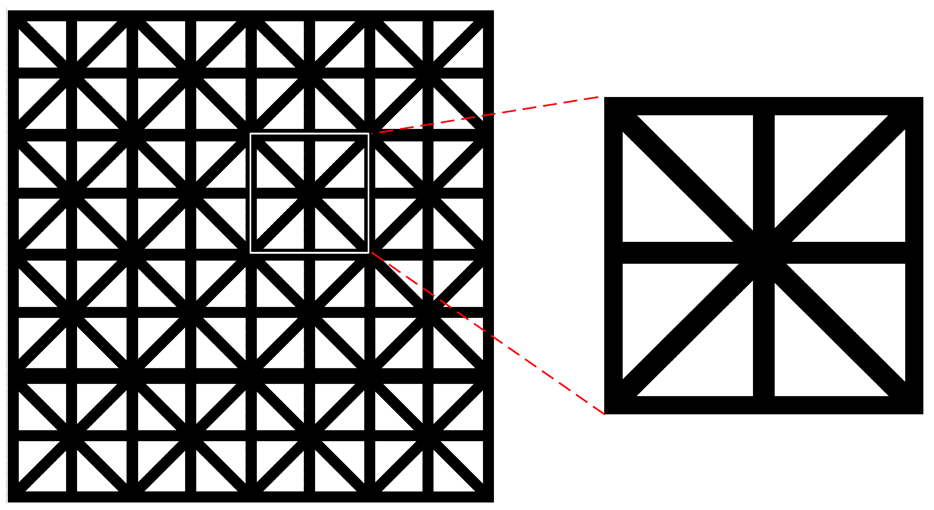
2. Analysis of Equivalent Mechanical Properties of Lattice Materials

EMsFEM is similar to the traditional finite element method (FEM) [42]. Its basic principle is to equate an RVE at the mesoscale to an macro-element in the FEM.The FEM is then applied to solve the equivalent stiffness matrix of the RVE. Typically, we consider such an RVE as a unit cell, illustrated in Figure 1. In this study, EMsFEM is chosen as the method for determining the equivalent stiffness of lattice materials.
In this approach, we identify a periodic region within the lattice material structure, considering it a unit cell with a truss structure at the mesoscale and a four-node finite element at the macro scale.
In a macroelement, the displacement of nodes inside the cell and macronodes needs to meet the following conditions:
u = N u
In Equation (1), u represents the displacement of nodes in the truss structure, while u represents the displacement of four macronodes, and N is the base function, which can represent the relationship between the displacement of macronodes and mesonodes. They are expanded as follows:
u = u 1 , v 1 , u 2 , v 2 , , u n , v n T , N = N x 1 T , N y 1 T , N x 2 T , N y 2 T , , N x n T , N y n T T u = u 1 , v 1 , u 2 , v 2 , u 3 , v 3 , u 4 , v 4 T
where N x i T and N y i T are further developed as follows:
N x i = N 1 x x i , N 1 x y i , N 2 x x i , N 2 x y i , N 3 x x i , N 3 x y i , N 4 x x i , N 4 x y i N y i = N 1 y x i , N 1 y y i , N 2 y x i , N 2 y y i , N 3 y x i , N 3 y y i , N 4 y x i , N 4 y y i
It is important to note that, as the unit cell is treated as a truss structure, we must ensure that the deformation of the mesounit cell, the continuity of the macroelement, and the displacement of the rigid body are satisfied during the macroelement’s deformation. Continuity in this context means that at the macroscale, the displacement of adjacent elements should be consistent—referred to as Requirement N j x y i = 0 ; i , j = 1 , 2 , 3 , 4 , i j . Additionally, to meet the rigid body displacement requirements of the element, it also needs to fulfill Requirement j = 1 4 N j x y i = 0 for any i. In terms of selecting the construction method of the base function, there are three methods [17] to construct the basis function: the method based on linear boundary conditions, the method based on oversampling technology, and the method based on periodic boundary conditions. Given that this article focuses on heterogeneous unit cells, we choose periodic boundary conditions to construct the base function.

2.1. Solution of Base Function

The solution of truss node displacement u can be considered a quadratic programming problem with equality constraints based on the principle of minimum potential energy:
f i n d u min Π = 1 2 u T K g u f T u s . t . B u = b
where Π is the finite element expression of the potential energy functional; K g is the global stiffness matrix of the mesotruss structure; B u = b is the constraint on displacement u ; B is a constraint matrix of order w × n ; w is the number of constraints; n is the total number of degrees of freedom; and b is the constraint case. This optimization problem can be solved by the Lagrange multiplier method, and the Lagrange function can be constructed by introducing Lagrange multiplier λ :
L u , λ = 1 2 u T K g u f T u λ T B u b
By considering u L u , λ = 0 and u L u , λ = 0 , we obtain:
K g B T B 0 u λ = f b
Taking into account Equations (1) and (2), the solution to Equation (5) is as follows:
u ¯ = Q f + R T b R = B K g 1 B T 1 B K g 1
From Equation (1), the base function can be expressed as:
N = u = R 1 T b 1 , R 2 T b 2 , , R i T b i , , R 8 T b 8

2.2. Solution of Equivalent Stiffness Matrix

We can consider the lattice material as a truss composed of bars as shown in Figure 2, where the strain energy of each bar is:
U e = 1 2 k e Δ L 2
where k e = E A L is the stiffness of the rod in the local coordinate system, E is the Young’s modulus of the rod; A is the cross-sectional area of rod; θ is the angle between the bar and the horizontal plane; and L is the length of the rod. Δ L is the deformation of the rod as follows:
Δ L = c o s θ u 1 s i n θ v 1 + c o s θ u 2 + s i n θ v 2 = θ e u e
The equivalent stiffness matrix of the element of the bar is:
K E = e N e T θ e T k e θ e N e

3. Multi-Material Optimization Formulations Based on Nash Equilibrium

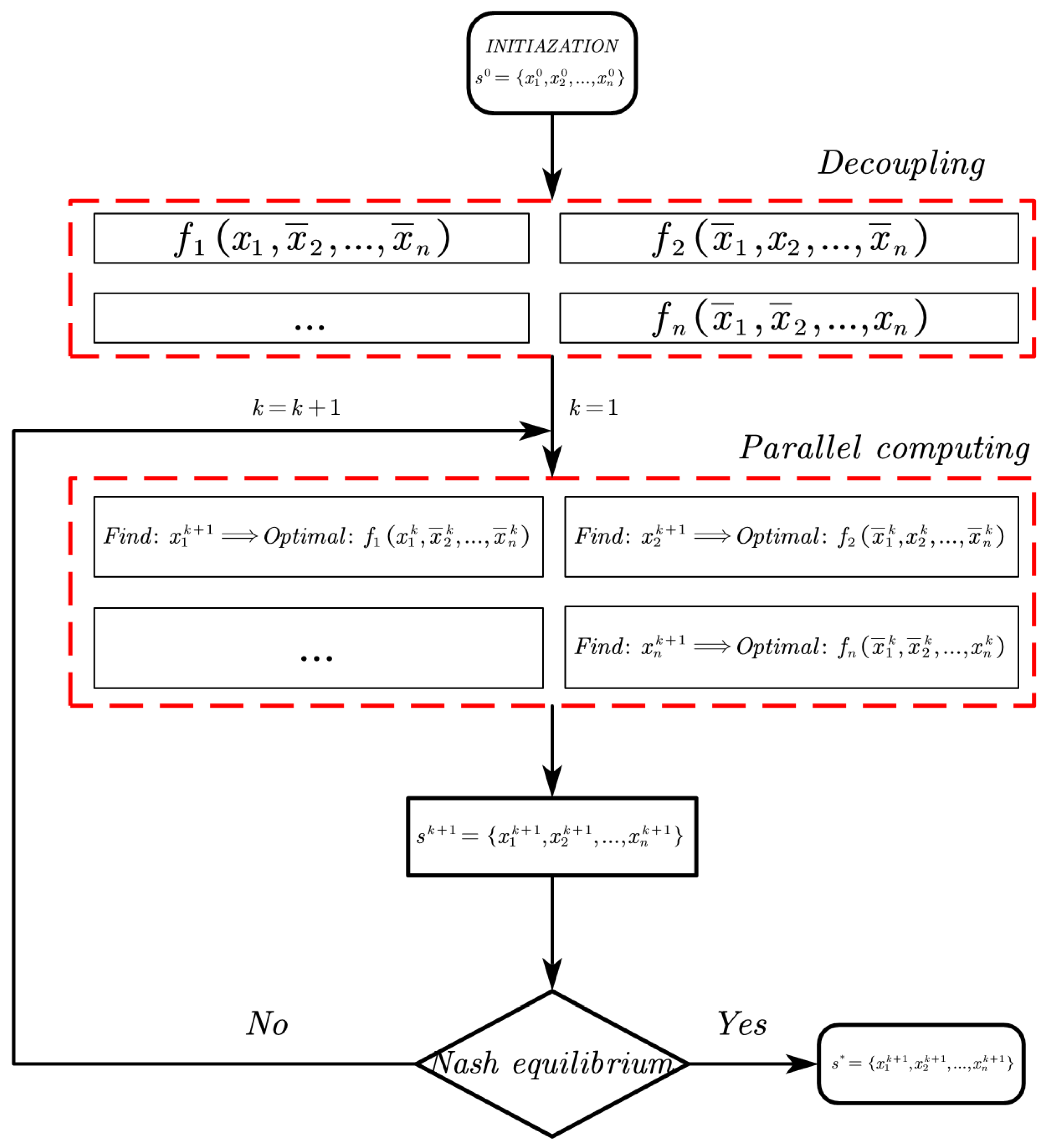
3.1. Nash Equilibrium Theory

The Nash game as proposed by Nash in his doctoral thesis [41], refers to a concept in game theory. In his paper, John Nash provided detailed explanations regarding the theory of non-cooperative equilibrium in games and the existence of equilibrium solutions. The fundamental concept of the Nash game is that each participant aims to maximize their own profits by independently selecting strategies from their respective strategy sets, while assuming that the strategies chosen by other participants remain unchanged.
In the context of multi-material structural optimization based on Nash game theory, we assume that the design variables for each material are denoted as S i . The set of all possible combinations in the game can be translated as:
S = S 1 S 2 S n
In each game, the set composed of each material in k-th round on each element is:
S i k = { x 1 k , x 2 k , , x n k } S
The game process for each material in round k + 1 is:
F i n d : x i k + 1 max f i ( x ¯ 1 k , , x i k , , x ¯ n k ) , i N
The game process described above continues until no participant can unilaterally change their strategy to further increase their profits. At this point, the combination of strategies chosen by each individual is referred to as the Nash equilibrium, described by Equation (15)
f i ( x 1 * , , x i * , , x n * ) f i ( x 1 * , , x j , , x n * ) , i , j N
Because all parties in the Nash equilibrium strategy are independent of each other, the game can run in parallel, so the Nash equilibrium strategy is naturally applicable to solving problems with parallel characteristics. Figure 3 shows the flow chart of multidisciplinary and multi-objective optimization problems based on the Nash equilibrium strategy. In this figure, f is the decoupled sub-function, which can be calculated in parallel in the iteration.

3.2. Multi-Material Optimization Formulations

For the optimization problem of multi-material structures, each material can be considered a game player, and the objective function associated with each material represents the player’s profit. The optimization problem for multi-material structures can be seen as a scenario in which all players in the game choose units to fill their respective design domains, aiming to optimize their individual objective functions.
According to Figure 3, the solution steps of the Nash game-based multi-material structure optimization problem are as follows: decouple the multi-material structure optimization problem into subproblems, where each subproblem corresponds to a single material. Then, independently solve these subproblems using commonly used topology optimization methods for single-material structures. In this article, the EMsFEM-based single-material optimization method is applied to solve these subproblems.

3.3. Optimization Subproblem Formulations

Unlike the Solid Isotropic Material with Penalization interpolation model commonly used in traditional topology optimization problems for single-material structures [22], the material interpolation model used in the optimization subproblem is shown in Equation (16). The equivalent stiffness matrix of each element is obtained by adding different materials at the corresponding element:
K e = i = 1 m K E M s F E M ( a i )
This paper employs the EMsFEM method to solve the material equivalent stiffness in a series of decoupled optimization subproblems. In each of these subproblems, only the design variable a e i corresponding to the specific material needs to be optimized, while the design variables of the other materials remain fixed at their values from the previous game.
The mathematical model of the optimization subproblem is shown in Equation (17):
F i n d : a i = [ a 1 i , a 2 i , , a D i ] T M i n i m i z e : C ( a i ) = F T U ( a i ) = e = 1 D u e T [ i = 1 m K E M s F E M ( a i ) ] u e S u b j e c t t o : V i ( x i ) = a i V 0 = e = 1 D a e i V e , i = 1 , 2 , , m F = KU 0 < a min a e i a max , i = 1 , 2 , , D i = 1 m a e i a max x ej constant , j = 1 , 2 , , m , j i
where a is the design variables of different materials, which is a D m matrix, D is the number of elements in the structure, and m represents the type of material. C ( a ) is the compliance; the equivalent stiffness matrix of element is calculated from EMsFEM. x e j c o n s t a n t means that when the design variables involved in this subproblem are optimized, the design variables of other subproblems remain unchanged. In this article, we choose the optimization criteria (OC) to update the design variables in the subproblem. The OC algorithm is an optimization criterion derived using the Lagrange multiplier method and the Karush–Kuhn–Tucker (KKT) conditions, which is Equation (18):
x e n e w = max ( x min , x e r ) , x e B e η max ( x min , x e r ) min ( x max , x e + r ) , x e B e η min ( x max , x e + r ) x e B e η , max ( x min , x e r ) x e B e η min ( x max , x e + r )
where r is a limit of the iteration step size of the design variable, η is the damping coefficient, generally taken as 0.5, and the B e is written as:
B e = c ( x ˜ ) x e ( λ v ( x ˜ ) x e ) 1
The optimization algorithm necessitates the derivation of both the objective function and the constraint with respect to the design variable. In this article, the multi-material optimization problem is decoupled into a single-material optimization subproblem, so the solution method for the derivative is also the same as that for the single-material optimization method [43].

3.4. Material Overlap Phenomenon And Solution

In this method, there are m types of materials and D macrostructural finite element elements. From Equation (17), it is evident that different materials can have design variables located at the same position within the design domain as depicted in the materials layout shown in Figure 4; this phenomenon is commonly referred to as material overlap.
In this article, we adopt an effective method to solve this problem. The solution is to restrict the materials that contribute less to the element stiffness after each iteration. The specific method is as follows:
  • After each iteration, search for overlapped elements in the entire design domain. The set of these supersaturated elements is:
    M = { e x e 1 + x e 2 + x e m > δ , e = 1 , 2 , D }
    where δ is the threshold value. When the design variable within a design domain exceeds a threshold, it is considered an overlapped element.
  • Calculate the equivalent stiffness of each material within the overlapped elements.
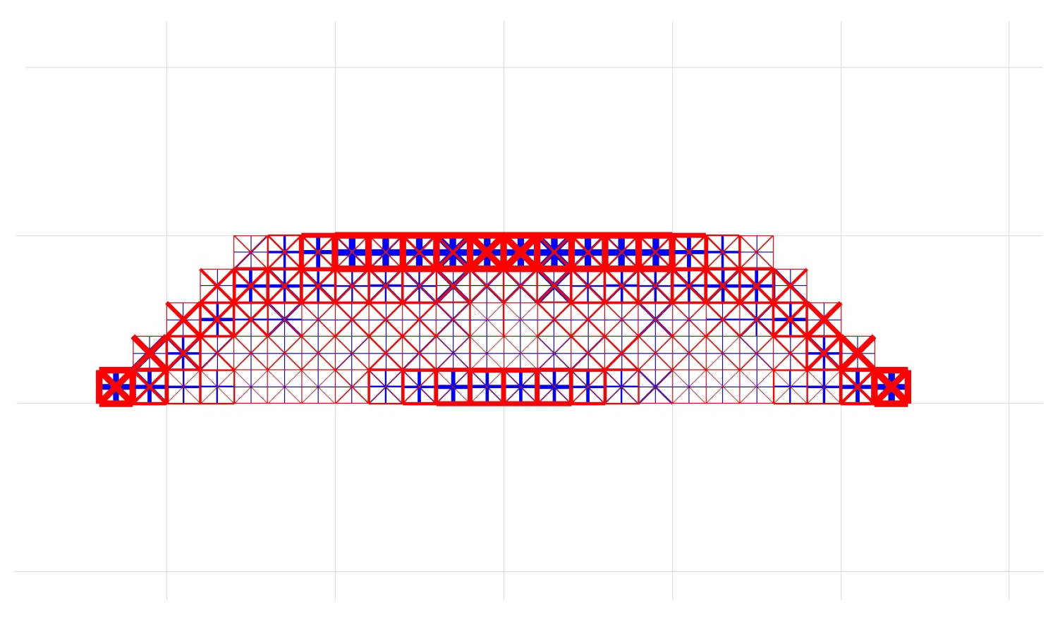
  • Compare the equivalent stiffness of each material within the overlapped elements, keep the design variable of material with the largest equivalent stiffness unchanged, and then restrict the design variables of other materials as follows:
    x e i = x e i , x e j = α x e j i f   E e i = max ( K e 1 , K e 2 , , K e m ) ( i j , j = 1 , 2 , m )
    where α is the penalty coefficient, which is generally taken as 0.5 based on engineering experience. The optimization results after adding suppression methods are shown in Figure 5, which can verify the effectiveness of the method.

4. Numerical Examples and Tests

In this section, we presented two examples and one test to validate the method proposed in this paper, which involves the intermediate layer being made of a single-structural material (called Material 1) shown in Figure 6 and a double cross-structural material (called Material 2) shown in Figure 7. Meanwhile, both have the same Young’s modulus with 2.0 × 10¹⁰ Pa. Regarding the mechanical properties of these two materials, they are typically determined using homogenization methods [15]. Wang et al. [44] conducted a mechanical performance analysis of these two materials. The results indicate that Material 1 exhibits superior tensile and compressive strength compared to Material 2, while Material 2 demonstrates better shear resistance compared to Material 1.

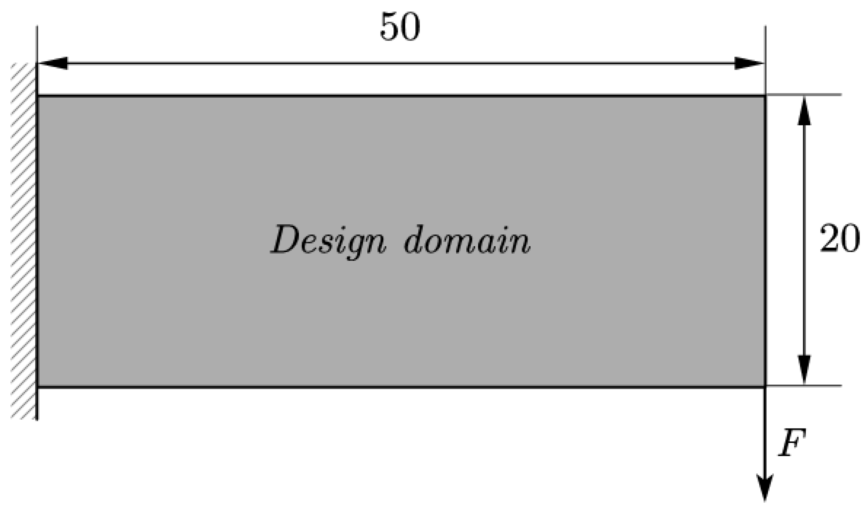
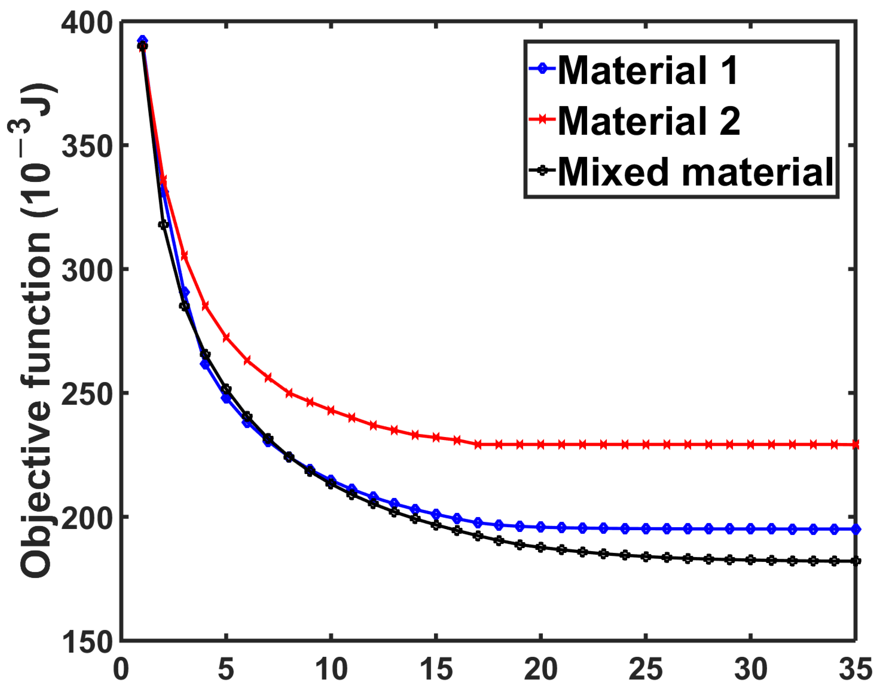
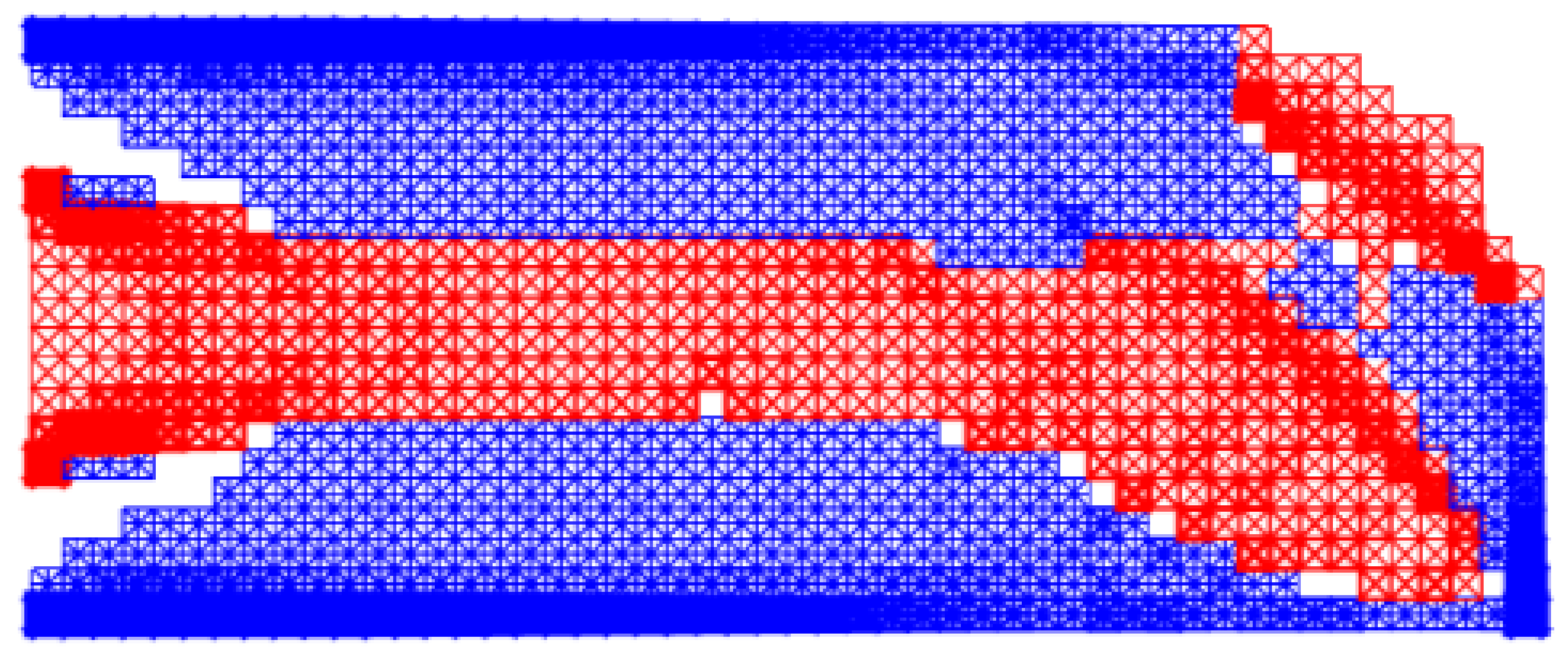
4.1. Cantilever Beam
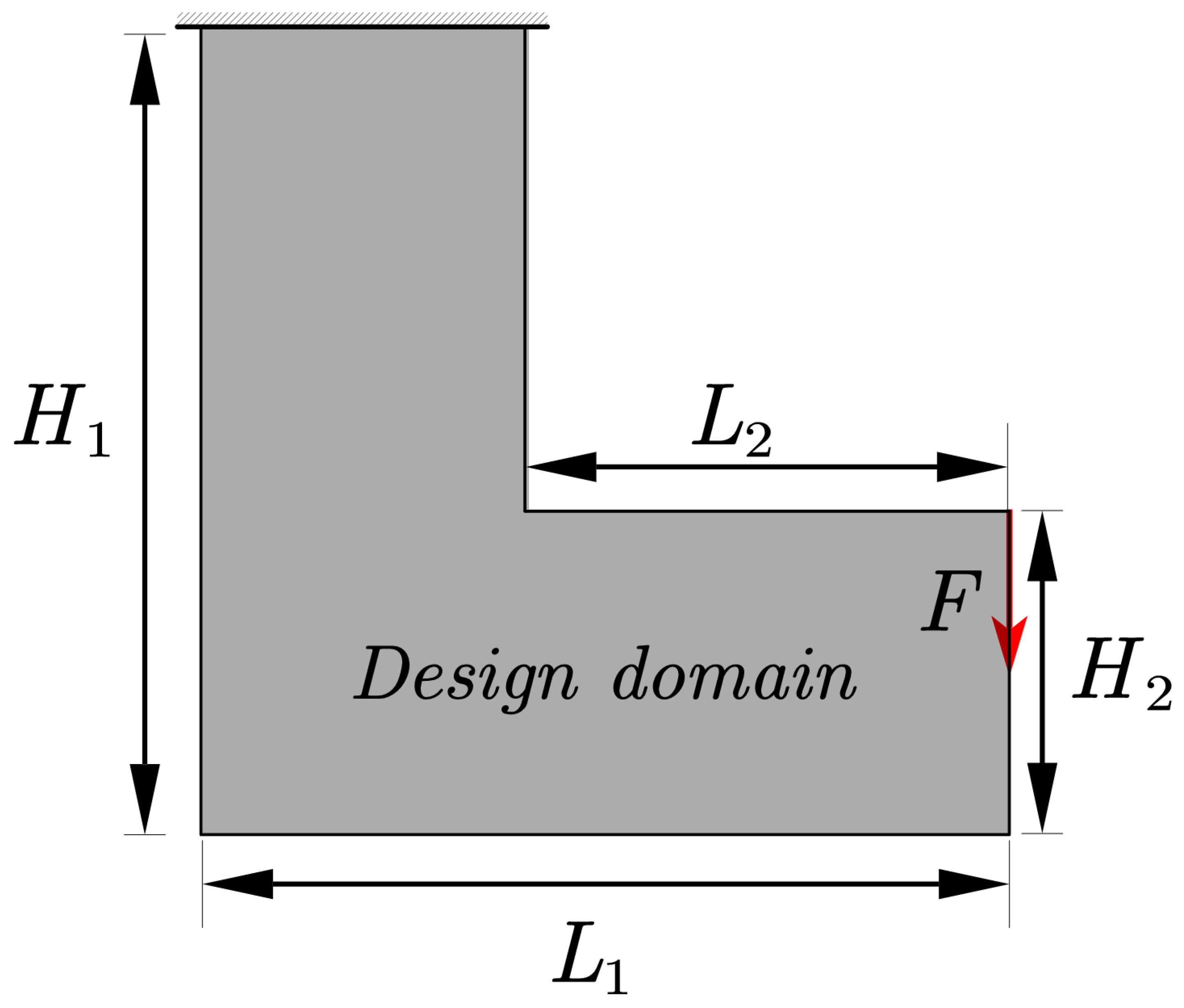
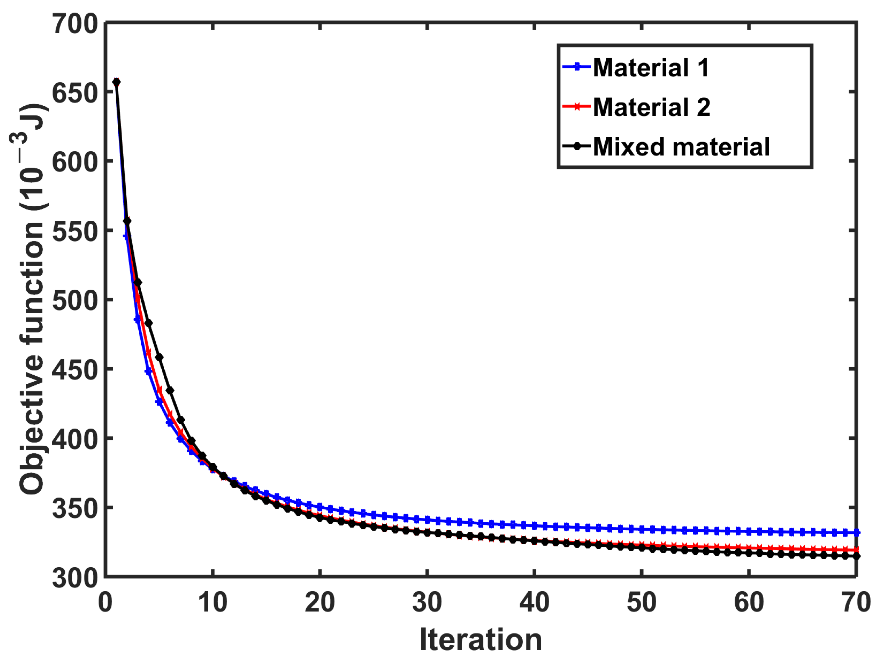
To illustrate the advantages of our method, we compare the performance results of using the single-material optimization method [43] (SMOM) and multi-material optimization method (MMOM) in this article. The example of the cantilever beam is shown in Figure 8. The cantilever beam dimensions are defined with a length of 50 mm and a height of 20 mm. A vertical unit load is applied at the lower right corner in a downward direction.
In SMOM, we adopt Material 1 (with a volume constraint of 0.2) and Material 2 (with a volume constraint of 0.2). In MMOM, we employ two types of materials, each subject to a volume constraint of 0.1, for the optimization process. The structure is divided into 50 × 20 elements while keeping the other material properties unchanged in these three methods.
The compliance iteration histories for the examples are depicted in Figure 9. In all examples, the compliance exhibits a notable reduction in the initial 20 iterations, followed by a gradual convergence rate, ultimately reaching convergence after 93 iterations. Figure 10 illustrates that in the cantilever beam example, the optimized design featuring a mixed material exhibits superior stiffness compared to the optimized design utilizing a single material. Specifically, the stiffness is measured at 0.182 J, representing a 6.67% reduction compared to Material 1 (0.195 J) and 20.5% reduction compared to Material 2 (0.229 J).
The optimized structure is depicted in Figure 11. It can be observed that in the structural design of the cantilever beam, Material 1, known for its robust tensile and compressive performance, is strategically distributed on the upper and lower sides of the cantilever beam. Meanwhile, Material 2, recognized for its excellent shear resistance, is distributed in the transition stage and the middle. This highlights an efficient materials distribution within the design domain.

4.2. L-Shaped Beam

In this example, the L-shaped beam to be optimized is shown in Figure 12. The parameters of the beam are L1 = 100 mm, L2 = 60 mm, H1 = 100 mm, and H2 = 60 mm. The upper edge of the structure is constrained, while a unit vertical downward load is applied to the lower right corner. We select the cross-sectional area of two materials as the design variable, with a variation range of 0-0.2. The design domain is discretized into 6400 elements, with volume constraints of 0.1 for each of the two materials. Similarly, we employ three methods: Material 1, Material 2, and a combination of materials, to optimize the design.
In Figure 13, it is evident that all three optimization problems converge after 70 iterations, with objective functions showing a significant decrease in the initial 20 iterations, followed by a slower convergence rate.
In terms of computational cost, the Nash equilibrium method applied in this article is utilized to concurrently solve the equivalent stiffness matrix for different materials. As depicted in Figure 14, there is minimal disparity in the computational costs among the three methods, averaging 155 s per iteration step.
Figure 15 shows the optimization results and the distribution of materials within the design domain. It is evident that Material 1 (blue in the figure), possessing a higher equivalent elastic modulus, is strategically distributed in areas experiencing significant tensile and compressive loads within the structure. Conversely, Material 2 (red in the figure), having a higher shear modulus, is allocated in regions where shear stress is predominant. This rational distribution of the two materials within the design domain results in an optimized structure with increased stiffness.

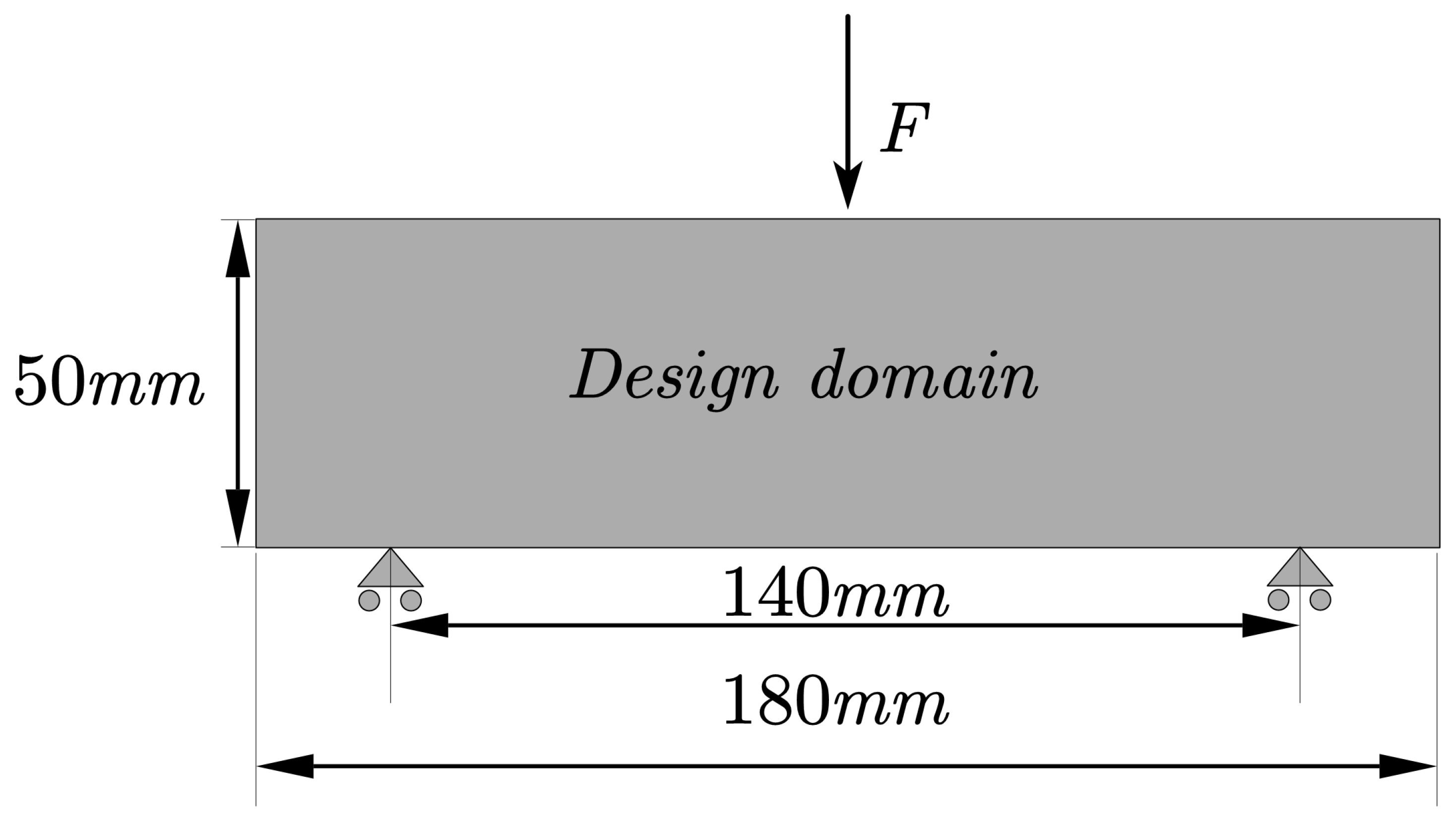
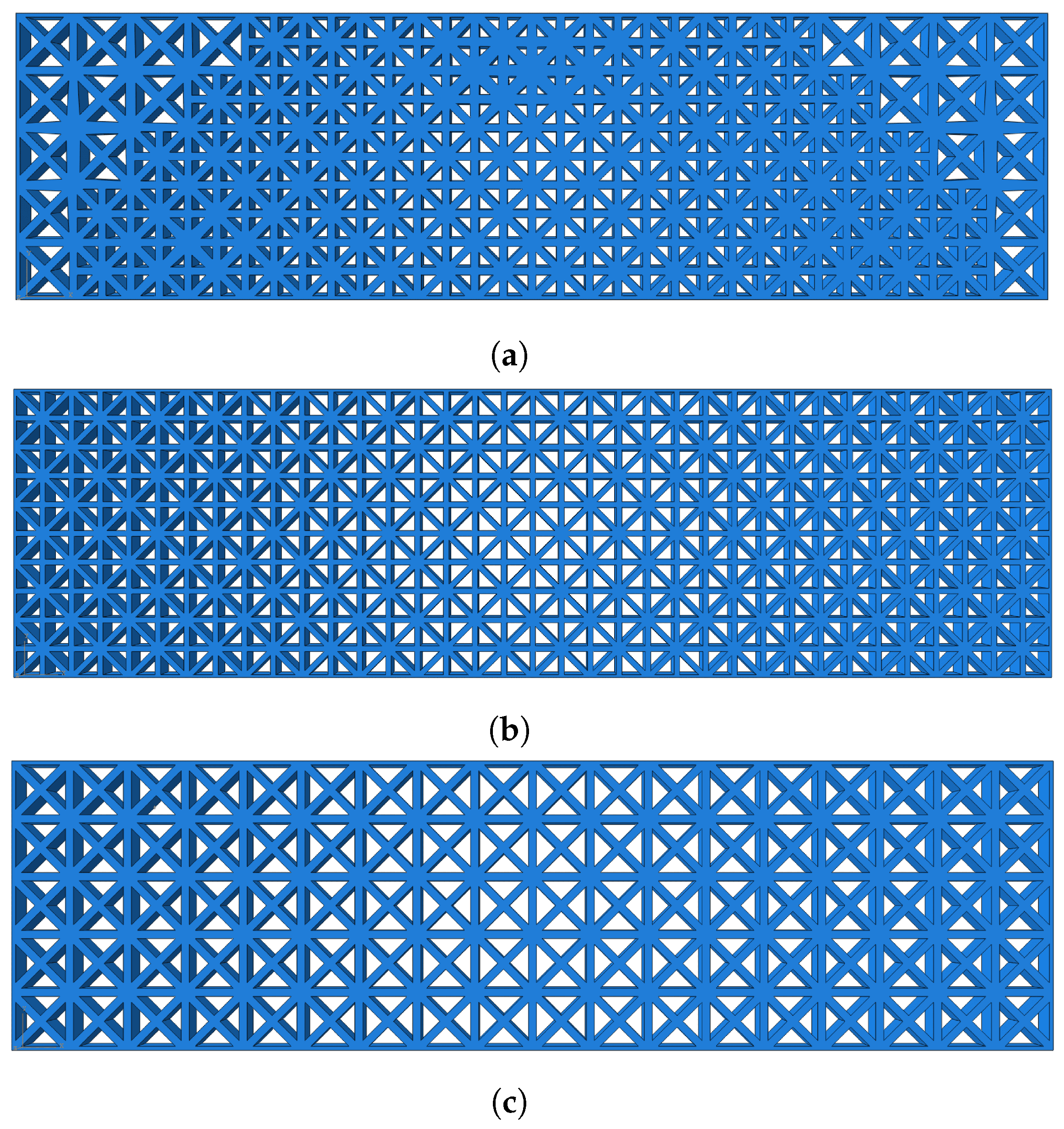
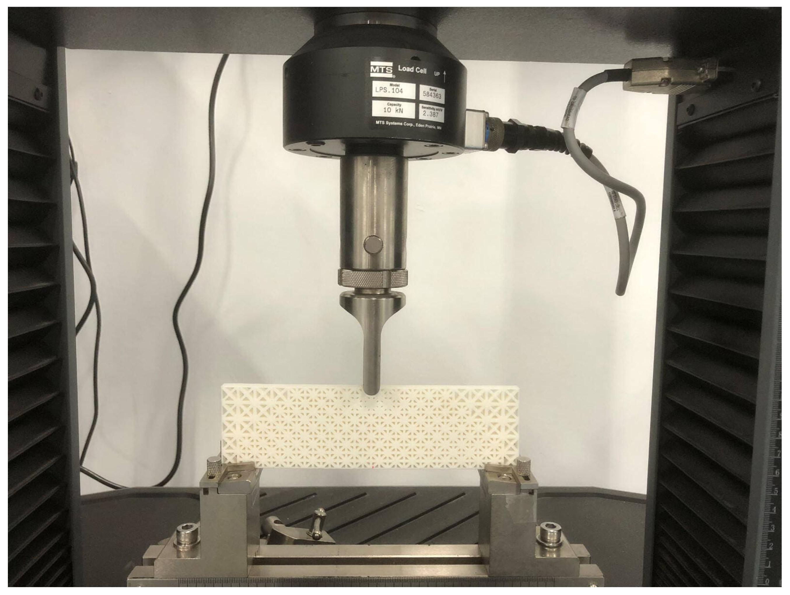
4.3. Three-Point Bending Test

In this section, we validate the optimization method proposed in this article through a three-point bending test. The structure, shown in Figure 16, is an MBB beam with a structural design domain of 180 mm × 50 mm and thickness of 8 mm. The midpoint of the upper edge of the structure is subjected to a vertical downward load while being symmetrically supported at a distance of 140 mm from the lower edge of the structure.
The design domain was discretized into 18 × 5 elements, with volume constraints of 0.2 for each of the two materials. Figure 17 shows the optimized structure of multiple materials, the unoptimized structure of Material 1, and the unoptimized structure of Material 2.
We can efficiently fabricate the optimized structure with the assistance of 3D-printing technology. As depicted in Figure 18, the specimens are produced using a 3D printer based on the Fused Deposition Modeling (FDM) technique [45]. Polylactic acid (PLA) is applied as the material, characterized by an elastic modulus of 3500 MPa, Poisson’s ratio of 0.2, and density of 1400 kg/m3. Considering the test requirements and printer precision, the design variables are confined within the range of 0.6 mm to 2 mm. Moreover, the post-processing techniques introduced by Liao et al. [46] are utilized for further enhancement of the optimized structure. The weights of the fabricated specimens are 56.82 g, 57.30 g, and 57.83 g, respectively.
The specimens are slowly loaded onto the MTS Exceed E43 Electronic Universal Testing Machine (10 KN) manufactured by MTS Systems Corporation in Shenzhen, China, at a longitudinal displacement speed of 1 mm/min. The test process is shown in Figure 19.
The force–displacement characteristics of the three types of MBB beam structures in the test are illustrated in Figure 20. It is evident that among the three force–displacement curves, the optimized structure exhibits a steeper slope compared to the other two, indicating that the multi-material optimized structure possesses superior stiffness performance in comparison to the unoptimized single-material structures.

5. Conclusions

This article introduces a multi-material optimization method based on the Nash equilibrium for lattice materials. EMsFEM is applied to resolve the equivalent mechanical properties of lattice materials. The Nash equilibrium is introduced to solve multi-material optimization problems. Considering the problem of material overlap, an effective suppression method is proposed. To validate the effectiveness of the proposed method, a cantilever beam example is implemented. The results demonstrate that the proposed method has better optimization results compared to the optimization method using a single material. The feasibility and stability of the method are evaluated using a L-shaped beam examples. The results indicate that materials with a higher equivalent elastic modulus are primarily allocated to regions experiencing tensile and compressive stress within the design area. Conversely, materials with a higher equivalent shear modulus are distributed in areas subject to significant shear stress. This finding highlights the capability of the method to effectively allocate materials based on their respective properties and the associated stress conditions within the design. Finally, we demonstrate through an MBB test that the proposed optimized specimen exhibits superior stiffness performance in comparison to the unoptimized specimen.

Author Contributions

Conceptualization, Y.X.; methodology, Y.X. and S.L.; validation, S.L. and W.H.; investigation, Y.X.; writing—original draft preparation, Y.X.; writing—review and editing, S.L.; visualization, W.H.; supervision, S.L.; funding acquisition, S.L. All authors have read and agreed to the published version of the manuscript.

Funding

This research was funded by the School of Aeronautic Science and Engineering at Beihang University.

Institutional Review Board Statement

Not applicable.

Informed Consent Statement

Not applicable.

Data Availability Statement

The data presented in this study are available on request from the corresponding author. The data are not publicly available due to privacy.

Acknowledgments

The authors are deeply grateful to the anonymous reviewers for their constructive comments, which have significantly enhanced the quality and presentation of this paper.

Conflicts of Interest

The authors declare no conflict of interest.

References

  1. Xiong, J.; Mines, R.; Ghosh, R.; Vaziri, A.; Ma, L.; Ohrndorf, A.; Christ, H.J.; Wu, L. Advanced Micro-Lattice Materials. Adv. Eng. Mater. 2015, 17, 1253–1264. [Google Scholar] [CrossRef]
  2. Surjadi, J.U.; Gao, L.; Du, H.; Li, X.; Xiong, X.; Fang, N.X.; Lu, Y. Mechanical Metamaterials and Their Engineering Applications. Adv. Eng. Mater. 2019, 21, 1800864. [Google Scholar] [CrossRef]
  3. Han, S.C.; Lee, J.W.; Kang, K. A New Type of Low Density Material: Shellular. Adv. Mater. 2015, 27, 5506–5511. [Google Scholar] [CrossRef]
  4. Sun, Z.; Guo, Y.; Shim, V. Deformation and energy absorption characteristics of additively-manufactured polymeric lattice structures—Effects of cell topology and material anisotropy. Thin-Walled Struct. 2021, 169, 108420. [Google Scholar] [CrossRef]
  5. Sajjad, U.; ur Rehman, T.; Ali, M.; Park, C.W.; Yan, W.M. Manufacturing and potential applications of lattice structures in thermal systems: A comprehensive review of recent advances. Int. J. Heat Mass Transf. 2022, 198, 123352. [Google Scholar] [CrossRef]
  6. Fawaz, A.; Hua, Y.; Le Corre, S.; Fan, Y.; Luo, L. Topology optimization of heat exchangers: A review. Energy 2022, 252, 124053. [Google Scholar] [CrossRef]
  7. Aslan, B.; Yıldız, A.R. Optimum design of automobile components using lattice structures for additive manufacturing. Mater. Test. 2020, 62, 633–639. [Google Scholar] [CrossRef]
  8. Wang, C.; Zhu, J.; Wu, M.; Hou, J.; Zhou, H.; Meng, L.; Li, C.; Zhang, W. Multi-scale design and optimization for solid-lattice hybrid structures and their application to aerospace vehicle components. Chin. J. Aeronaut. 2021, 34, 386–398. [Google Scholar] [CrossRef]
  9. Zhu, J.H.; Zhang, W.H.; Xia, L. Topology Optimization in Aircraft and Aerospace Structures Design. Arch. Comput. Methods Eng. 2016, 23, 595–622. [Google Scholar] [CrossRef]
  10. Hulme, J.; Sakhaei, A.H.; Shafiee, M. Mechanical analysis and additive manufacturing of 3D-printed lattice materials for bone scaffolds. Mater. Today Proc. 2023. [Google Scholar] [CrossRef]
  11. Uribe-Lam, E.; Treviño-Quintanilla, C.D.; Cuan-Urquizo, E.; Olvera-Silva, O. Use of additive manufacturing for the fabrication of cellular and lattice materials: A review. Mater. Manuf. Process. 2021, 36, 257–280. [Google Scholar] [CrossRef]
  12. Wallach, J.; Gibson, L. Mechanical behavior of a three-dimensional truss material. Int. J. Solids Struct. 2001, 38, 7181–7196. [Google Scholar] [CrossRef]
  13. Quintana-Alonso, I.; Fleck, N.A. Fracture of Brittle Lattice Materials: A Review. Major Accomplishments in Composite Materials and Sandwich Structures; Springer Science & Business Media: Berlin/Heidelberg, Germany, 2010. [Google Scholar]
  14. Willis, J.R. Variational and Related Methods for the Overall Properties of Composites. Adv. Appl. Mech. 1981, 21, 1–78. [Google Scholar]
  15. Bendsoe, M.P.; Sigmund, O. Material interpolation schemes in topology optimization. Arch. Appl. Mech. 1999, 69, 635–654. [Google Scholar] [CrossRef]
  16. Yan, J. Preddicion of equivalent elastic properties of truss materials with periodic microstructure and the scale effects. Acta Mech. Solida Sin. 2005, 26, 421. [Google Scholar]
  17. Zhang, H.W.; Wu, J.K.; Lv, J.; Fu, Z.D. Extended multiscale finite element method for mechanical analysis of heterogeneous materials. Acta Mech. Solida Sin. 2010, 26, 899–920. [Google Scholar] [CrossRef]
  18. Berinskii, I. Elastic networks to model auxetic properties of cellular materials. Int. J. Mech. Sci. 2016, 115–116, 481–488. [Google Scholar] [CrossRef]
  19. Safina, L.; Baimova, J.; Krylova, K.; Murzaev, R.; Mulyukov, R. Simulation of metal-graphene composites by molecular dynamics: A review. Lett. Mater. 2020, 10, 351–360. [Google Scholar] [CrossRef]
  20. Liu, T.; Guessasma, S.; Zhu, J.; Zhang, W. Designing Cellular Structures for Additive Manufacturing Using Voronoi–Monte Carlo Approach. Polymers 2019, 11, 1158. [Google Scholar] [CrossRef]
  21. Bendsøe, M.P.; Kikuchi, N. Generating optimal topologies in structural design using a homogenization method. Comput. Methods Appl. Mech. Eng. 1988, 71, 197–224. [Google Scholar] [CrossRef]
  22. Bendsoe, M.P.; Sigmund, O. Topology Optimization: Theory, Methods, and Applications; Springer Science & Business Media: Berlin/Heidelberg, Germany, 2003. [Google Scholar]
  23. Allaire, G.; Jouve, F. Structural Optimization by the Level-Set Method; Birkhäuser: Basel, Switzerland, 2003. [Google Scholar]
  24. Sigmund, O.; Maute, K. Topology optimization approaches. Struct. Multidiscip. Optim. 2013, 48, 1031–1055. [Google Scholar] [CrossRef]
  25. Sigmund, O. Design of multiphysics actuators using topology optimization—Part II: Two-material structures. Comput. Methods Appl. Mech. Eng. 2001, 190, 6605–6627. [Google Scholar] [CrossRef]
  26. Stegmann, J.; Lund, E. Discrete material optimization of general composite shell structures. Int. J. Numer. Methods Eng. 2007, 62, 2009–2027. [Google Scholar] [CrossRef]
  27. Zhou, S.; Wang, M.Y. Multimaterial structural topology optimization with a generalized Cahn–Hilliard model of multiphase transition. Struct. Multidiscip. Optim. 2007, 33, 89–111. [Google Scholar] [CrossRef]
  28. Hvejsel, C.F.; Lund, E. Material interpolation schemes for unified topology and multi-material optimization. Struct. Multidiscip. Optim. 2011, 43, 811–825. [Google Scholar] [CrossRef]
  29. Tajs-Zielińska, K.; Bochenek, B. Cellular Automata Approach to Topology Optimization of Graded Multi-Material Structures. Appl. Sci. 2023, 13, 2929. [Google Scholar] [CrossRef]
  30. Zheng, R.; Yi, B.; Peng, X.; Yoon, G.H. An Efficient Code for the Multi-Material Topology Optimization of 2D/3D Continuum Structures Written in Matlab. Appl. Sci. 2024, 14, 657. [Google Scholar] [CrossRef]
  31. Andreassen, E.; Clausen, A.; Schevenels, M.; Lazarov, B.S.; Sigmund, O. Efficient topology optimization in MATLAB using 88 lines of code. Struct. Multidiscip. Optim. 2011, 43, 1–16. [Google Scholar] [CrossRef]
  32. Sohrabi, M.K.; Azgomi, H. A Survey on the Combined Use of Optimization Methods and Game Theory. Arch. Comput. Methods Eng. 2020, 27, 59–80. [Google Scholar] [CrossRef]
  33. Greiner, D.; Periaux, J.; Emperador, J.M.; Galván, B.; Winter, G. Game Theory Based Evolutionary Algorithms: A Review with Nash Applications in Structural Engineering Optimization Problems. Arch. Comput. Methods Eng. 2017, 24, 703–750. [Google Scholar] [CrossRef]
  34. Louis, A.K. Feature reconstruction in inverse problems. Inverse Probl. 2011, 27, 065010. [Google Scholar] [CrossRef]
  35. Maxwell, J.C. I.—On Reciprocal Figures, Frames, and Diagrams of Forces. Trans. R. Soc. Edinb. 1870, 26, 1–40. [Google Scholar] [CrossRef]
  36. Greiner, D.; Emperador, J.M.; Winter, G. Single and multiobjective frame optimization by evolutionary algorithms and the auto-adaptive rebirth operator. Comput. Methods Appl. Mech. Eng. 2004, 193, 3711–3743. [Google Scholar] [CrossRef]
  37. Holmberg, E.; Thore, C.J.; Klarbring, A. Game theory approach to robust topology optimization with uncertain loading. Struct. Multidiscip. Optim. 2017, 55, 1383–1397. [Google Scholar] [CrossRef]
  38. Habbal, A.; Petersson, J.; Thellner, M. Multidisciplinary topology optimization solved as a Nash game. Int. J. Numer. Methods Eng. 2010, 61, 949–963. [Google Scholar] [CrossRef]
  39. Périaux, J.; Chen, H.Q.; Mantel, B.; Sefrioui, M.; Sui, H.T. Combining game theory and genetic algorithms with application to DDM-nozzle optimization problems. Finite Elem. Anal. Des. 2001, 37, 417–429. [Google Scholar] [CrossRef]
  40. Desideri, J.A. Platform for Prioritized Multi-Objective Optimization by Metamodel-Assisted Nash Games; Inria Sophia Antipolis: Valbonne, France, 2019. [Google Scholar]
  41. Nash, J.F. Equilibrium Points in N-Person Games. Proc. Natl. Acad. Sci. USA 1950, 36, 48–49. [Google Scholar] [CrossRef]
  42. Dhatt, G.; Lefrançois, E.; Touzot, G. Finite Element Method; John Wiley & Sons: Hoboken, NJ, USA, 2012. [Google Scholar]
  43. Wu, T.; Li, S. An efficient multiscale optimization method for conformal lattice materials. Struct. Multidiscip. Optim. 2021, 63, 1063–1083. [Google Scholar] [CrossRef]
  44. Chuang, W.; Hong, Z.J.; Hong, Z.W.; Ying, L.S.; Jie, K. Concurrent topology optimization design of structures and non-uniform parameterized lattice microstructures. Struct. Multidiscip. Optim. 2018, 58, 35–50. [Google Scholar]
  45. Mohamed, O.A.; Masood, S.H.; Bhowmik, J.L. Optimization of fused deposition modeling process parameters:a review of current research and future prospects. Adv. Manuf. 2015, 3, 42–53. [Google Scholar] [CrossRef]
  46. Liao, Z. Graded-density Lattice Structure Optimization Design Based on Topology Optimization. J. Mech. Eng. 2019, 55, 65. [Google Scholar] [CrossRef]
Figure 1. Macrostructure and mesoscopic representative volume element.
Applsci 14 02934 g001
Figure 2. Element of the bar with angle θ relative to the horizontal plane.
Applsci 14 02934 g002
Figure 3. The flow chart of multidisciplinary and multi-objective optimization problems based on the Nash equilibrium strategy.
Applsci 14 02934 g003
Figure 4. The occurrence of element overlap, where different materials are combined, is considered unacceptable in manufacturing.
Applsci 14 02934 g004
Figure 5. Optimized results after suppression, showing that different materials remain independent within their respective elements.
Applsci 14 02934 g005
Figure 6. Material 1 with design variable A 1 .
Applsci 14 02934 g006
Figure 7. Material 2 with design variable A 2 .
Applsci 14 02934 g007
Figure 8. A cantilever beam structure with length of 50 mm and width of 20 mm.
Applsci 14 02934 g008
Figure 9. The optimization process of the cantilever beam, where the objective functions of the three methods converge rapidly in the first 15 steps of the iteration and slowly around 25 steps.
Applsci 14 02934 g009
Figure 10. The best solution of the cantilever beam is that mixed materials (0.182 J) are 6.67% stronger than Material 1 (0.195 J) and 20.5% stronger than Material 2 (0.229 J).
Applsci 14 02934 g010
Figure 11. Blue represents material 1, red represents material 2, and optimized cantilever beam that achieves reasonable distribution of two materials.
Applsci 14 02934 g011
Figure 12. L-shaped beam structure with L1 = 100 mm, L2 = 60 mm, H1 = 100 mm, and H2 = 60 mm.The top is constrained by a fixed support, and the red arrow represents a unit vertical downward force.
Applsci 14 02934 g012
Figure 13. The optimization process of L-shaped beam. The optimized objective function values of the three methods: mixed material, 0.315 J; Material 2, 0.319 J; Material 1, 0.332 J.
Applsci 14 02934 g013
Figure 14. The iteration time for each step of the three methods is between 150 s and 166 s, so there is not much difference in the optimization time cost among the three methods.
Applsci 14 02934 g014
Figure 15. Optimized L-shaped beam structure, where two materials achieve a reasonable distribution within the design domain based on their own mechanical properties.
Applsci 14 02934 g015
Figure 16. Messerschmitt–Bolkow–Blohm (MBB) beam structure for three-point bending test.
Applsci 14 02934 g016
Figure 17. Models for 3D printing: (a) optimized model, (b) Material 1 model, (c) Material 2 model.
Applsci 14 02934 g017
Figure 18. The upper part is the optimized specimen, the middle part is the unoptimized Material 1 specimen, and the lower part is the unoptimized Material 2 specimen.
Applsci 14 02934 g018
Figure 19. The device used is MTS Exceed E43 Electronic Universal Testing Machine (10KN) with a loading speed of 1 mm per minute.
Applsci 14 02934 g019
Figure 20. Test results: The horizontal axis represents the vertical displacement at the loading point, while the vertical axis represents the magnitude of pressure applied to the displacement.
Applsci 14 02934 g020
Disclaimer/Publisher’s Note: The statements, opinions and data contained in all publications are solely those of the individual author(s) and contributor(s) and not of MDPI and/or the editor(s). MDPI and/or the editor(s) disclaim responsibility for any injury to people or property resulting from any ideas, methods, instructions or products referred to in the content.

