Abstract
With the further development of China’s coal resources, mining operations are constantly transferred to the deep soft rock. As such, the mine roadway is under the action of high geostress, the surrounding rock body engineering properties are poor, the overall strength is low, the traditional support method struggles to meet the needs of safe production, and the surrounding rock control has become a major technical challenge. This paper relies on the actual project, analyzes the destabilization mechanism of the roadway, analyzes the deformation of the peripheral rock of the deep roadway, determines the physical and mechanical parameters of the peripheral rock through indoor tests, establishes numerical analysis model, proposes to adopt the joint support scheme of anchor rods + anchor cables + a 36U-type steel metal bracket + a laying net + a laying mat + filling behind the wall, and monitors the displacement of peripheral rock of the roadway on a regular basis by using the numerical display convergence meter, and then obtains the displacement of the peripheral rock of the roadway after excavation as well as under the influence of the quarrying movement. Under the influence of the roadway perimeter rock displacement, we evaluate the reasonableness of the support program, as well as the safe and effective control of the roadway perimeter rock, to achieve the ideal roadway perimeter rock support and control effect.
1. Introduction
As the most important energy source in China, coal is mainly mined by open-pit mining and shaft mining. Shaft mining has always been the most important mining method in China, and the biggest problem faced by this mining method is how to effectively control the roadway rock. In recent years, China’s roadway perimeter rock has mainly used a combination of anchor rods, anchor cables, and steel supports. In most cases, these support methods can be economical and effective in maintaining the stability of the roadway perimeter rock [1,2,3,4,5,6]. As the main structure of the anchor network support, the anchor can maximize the self-supporting ability of the surrounding rock and actively reinforce the surrounding rock, while the timing of anchor application is the most important factor affecting anchor support. In the actual project, the anchor system not only has to withstand the pressure of the original rock, but it is also subject to the influence of the mining pressure, which means that the designed support structure must be able to withstand the original rock stress and mining pressure, so as to achieve the expected support effect. However, as the mining conditions become more and more complex, such as with weak and fragile peripheral rock, peripheral rock stress increases, i.e., if you do not adjust the original support, it will lead to the support structure becoming damaged, or even failing. This requires a specific analysis of the specific surrounding rock conditions to avoid situations where the anchor force is excessive is some places while being insufficient in others [7,8,9].
In order to reduce operating costs and to ensure safe production at the same time, the roadway support program also needs to be more economical and reasonable, improve support efficiency, and reduce support costs. Coal mine roadway excavation and support is a complex process of dynamic change, generally following the “gravitational field disturbance—support—stress field balance” model. With such a law of change, the corresponding roadway support parameters need to be adjusted according to the specific circumstances to ensure that the stress balance of the surrounding rock deformation can be controlled to ensure effective support [10,11,12,13].
With the gradual depletion of shallow coal resources, mining operations must be continuously developed in deeper locations. As such, the roadway will be in an environment of high geostress long-term action, and the traditional support structure will not meet the needs of safe production due to higher requirements for the support structure. The deep rock layer is characterized by a complex geological structure, high ground stress and rock fissure development, etc. Reasonable and effective control technology of deep tunnel perimeter rock can ensure safe production on the one hand and reduce the operation cost of the tunnel on the other hand, while increasing the digging efficiency at the same time. Under the influence of different geological conditions, seeking a more reasonable roadway support program is of great significance to the safe production of coal mines [14,15,16,17,18,19]. Therefore, this paper takes the 2500 transportation roadway of a mine as the engineering background and puts forward the concept of “stress-balanced” support, which reduces the support cost and improves the comprehensive benefit on the basis of effective control of roadway perimeter rock.
2. Roadway Surrounding Rock Control Technology
The factors that determine the stability of the surrounding rock mainly include the strength of the surrounding rock, the stress of the surrounding rock, and the supporting structure. Therefore, the key to maintaining the stability of the tunnel perimeter rock lies in improving the strength of the perimeter rock, reducing the pressure of the perimeter rock, and a reasonable support scheme. Peripheral rock stress mainly comes from the concentration of peripheral rock stress after tunneling and mining pressure, which leads to deformation of the peripheral rock, which, if not controlled, will lead to excessive deformation and even collapse. Reasonable arrangement of the roadway location can reduce the impact of mining but is subject to the constraints of mining conditions. Unpressurizing the surrounding rock can reduce the pressure of the surrounding rock to a certain extent, and grouting can also reinforce the surrounding rock and improve the strength of the surrounding rock. However, the support structure is an active measure, which plays a decisive role in controlling the deformation of the surrounding rock [20,21,22,23].
2.1. Mechanics of Roadway Destabilization
Stratum pressure is the inevitable result of the stress redistribution after roadway excavation and the interaction with surrounding rock deformation, which is also the essence of the mechanism leading to roadway instability. If the stress exceeds the plastic limit or strength limit of the surrounding rock, the surrounding rock will be deformed and broken. Loosening pressure, deformation pressure, and expansion pressure work together, and if the support structure is not timely or provides an insufficient support force, deformation pressure and expansion pressure will damage the surrounding rock, and then be transformed into loosening pressure, leading to the destruction of the entire surrounding rock structure due to instability.
Loosening pressure tends to appear in the roof and the two gangs of the roadway, and part of the surrounding rock after stress redistribution forms a loose body, which produces the effect of bubbling down and extrusion under the influence of stratigraphic conditions and the rock structure. In addition to the loosening pressure, the role of deformation pressure cannot be ignored. Under the action of secondary stress, stress redistribution produces stress concentration. Local elastic–plastic deformation of the surrounding rock will occur, and its deformation effect on the supporting structure produces pressure. If the rock body itself has high strength, the deformation range can be controlled within the allowable range, and then in the plastic zone boundary to form a strong supporting force holding ring structure. If the body comprises weak surrounding rock with low strength, the plastic deformation is difficult to effectively control, the surrounding rock ruptures, and the deformation pressure continues to increase, leading to the destabilization of the roadway. The resistance produced by the support structure basically comes from the deformation pressure of the surrounding rock. The earlier the support structure is applied, the smaller the plastic deformation of the surrounding rock is, and the greater the deformation pressure it can endure. On the contrary, the later the supporting structure is applied, the larger the plastic deformation of surrounding rock is, and the smaller the deformation pressure is. In conclusion, the timing of the support structure is very critical: too early and it will be subjected to excessive deformation pressure, leading to the destruction of the support structure; too late and there will be too large a deformation of the surrounding rock, which may lead to the destabilization of the surrounding rock and the formation of loosening pressure [24,25,26].
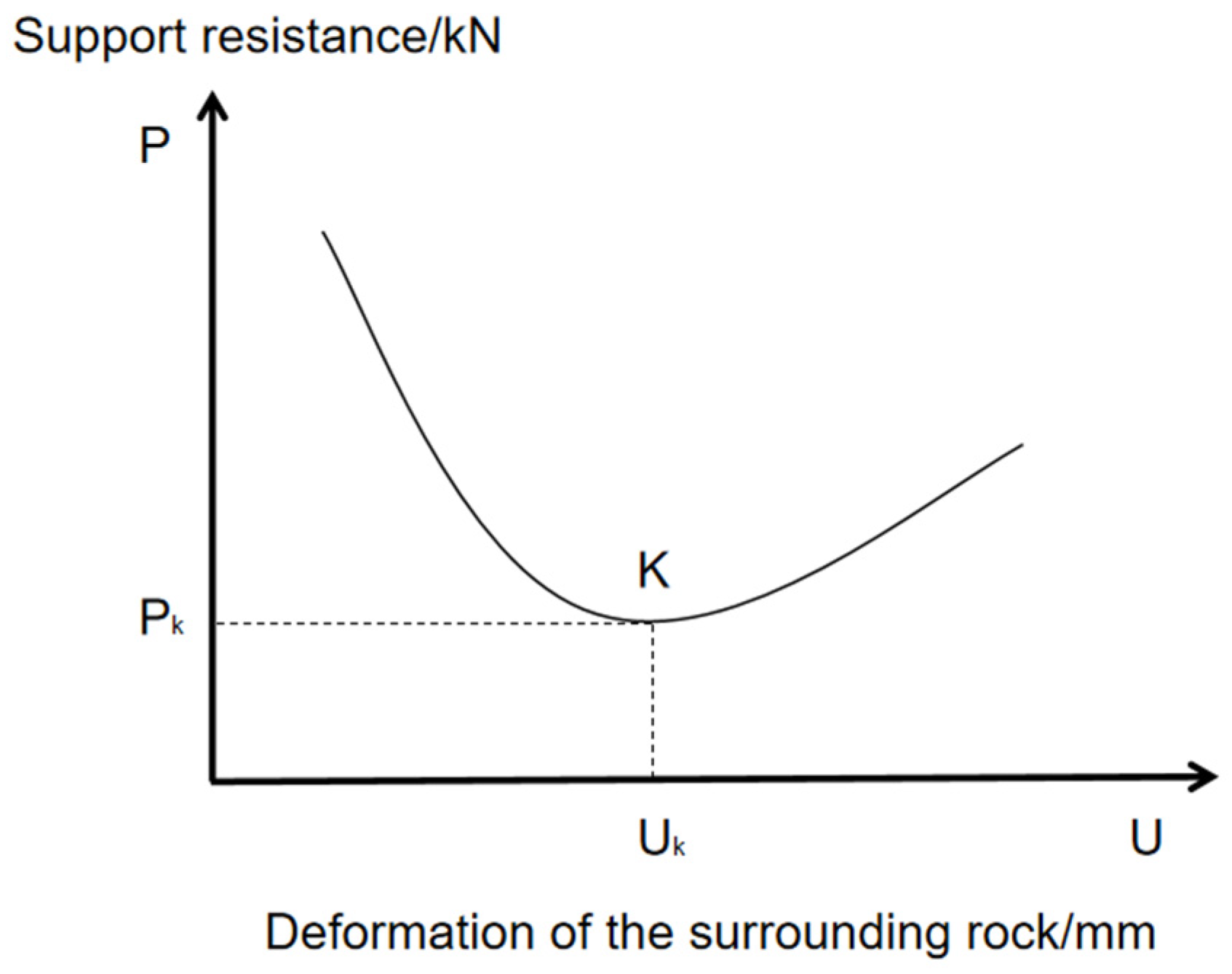
As far as coal mine roadway engineering is concerned, the surrounding rock of the roadway is usually a layered structure, mostly made up of soft rock. As such, its overall strength is low, constrained by the roadway layout, and often affected by the mining pressure. The rupture and delamination of the rock layer are the main causes of the damage to the roof of the roadway, and the elastic–plastic deformation of the surrounding rock is completed within a short period of time after the excavation. In order to prevent further deformation of the surrounding rock, it is necessary to have a suitable support timing and support program. The relationship curve between the peripheral rock deformation U and the support resistance P after tunneling is shown in Figure 1 [27]. In the relationship curve, it can be seen that if you want to minimize the peripheral rock deformation U, a larger support resistance P is required, resulting in higher requirements for the support structure. When the peripheral rock deformation U exceeds the maximum permissible value, the original peripheral rock structure will be damaged, resulting in the formation of a peripheral rock loose body and the formation of loose pressure on the supporting structure, increasing the load borne by the supporting structure. If the support is carried out at point K in the relationship curve, although the deformation of the surrounding rock increases in the short term, in the long term, the support is able to maintain the stability of the surrounding rock with the smallest support resistance, which better limits the development of deformation.
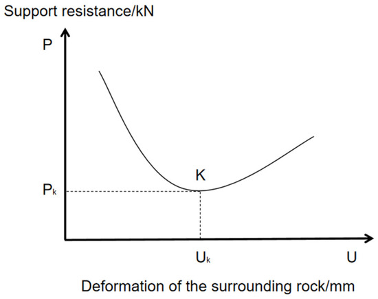
Figure 1.
Relationship curve between the deformation of the roadway enclosure and the support resisting force.
2.2. Analysis of Deformation of Broken Surrounding Rock in Deep Roadway
For the deep peripheral rock tunnel with a large burial depth, under the influence of long-term high geostress, it generally shows strong creep characteristics, and it is difficult to support. This kind of soft rock tunnel in the excavation after digging very easily produces plastic deformation, as the ground stress is strong, and the support structure undergoes deformation and fracturing until destruction. Therefore, after the roadway excavation, how to apply the support structure in a timely fashion, improve the self-supporting ability of the surrounding rock, control the loosening, and inhibit the deformation, are key to the controlling the surrounding rock.
For this reason, the damage mechanism of the roadway support, the distribution of the surrounding rock stress, and the creep phenomenon of the surrounding rock are inseparable and need to be studied as a whole. Assuming that the surrounding rock is uniform and that the roadway section is circular, under the action of radial stress, after a certain time ΔT, the radial creep distance of the surrounding rock is ; then, the creep rate υ of the surrounding rock is proportional to the radial gradient, as in the following Equation (1):
where is the radial stress in the surrounding rock at r from the center of the roadway, is the radial stresses in the surrounding rock around the roadway, is the radial distance of the surrounding rock around the roadway, is a point with zero distance from the center of the lane, and is the perimeter rock creep coefficient.
Therefore, in order to reduce the radial stress gradient of the surrounding rock, it is necessary to increase the bearing capacity of the support, which in turn increases the radial stress of the surrounding rock. In order to effectively control or even prevent the creep of the surrounding rock, theoretically, it is necessary to increase the radial stress of the surrounding rock around the roadway until it is equal to the original radial stress, i.e., , . If the back of the support wall is damaged by the extrusion of radial stress , then the rock becomes crushed. After squeezing into the support space, the back of the wall becomes a broken rock body, and the high stress area will be transferred to the deeper part of the surrounding rock. When the stress difference is certain, it can effectively reduce the creep rate and improve the supporting capacity of the supporting material.
Creep coefficient K is a parameter that describes the physical properties of the surrounding rock, as can be seen from Equation (1); if , then , which indicates that the surrounding rock is a stable rigid body and does not need any support. The larger the value of K, the stronger the creep of the surrounding rock. Therefore, the value of K has an important influence on the creep rate of the surrounding rock.
Since both the magnitude and direction of the creep rate of the surrounding rock are different, Equation (1) can be rewritten as follows:
Due to the different nature of the roadway enclosure, Equation (2) can be rewritten as follows:
If the creep phenomenon of the surrounding rock is regarded as a slow flow of a viscous medium, the movement of the surrounding rock should satisfy the following continuity equation:
Substituting Equation (3) into Equation (4) gives the following:
where are the rock creep coefficients in the corresponding axial directions, respectively.
Equation (5) can be referred to as the differential equation for creep of the roadway perimeter. This equation is valid for a certain range of R-domains beyond the roadway perimeter.
Obviously, as long as Equation (1) and Equation (5) hold, the boundary conditions of the enclosing rock in the R-domain are known, as follows:
or
where are the inner and outer boundaries of the roadway enclosure, respectively. is the perimeter rock creep per unit length around the roadway. is the stress distribution function on the R-domain boundary of the tunnel envelope. is the stress distribution function of the surrounding rock in the R domain. is the creep in the surrounding rock per unit length of the roadway boundary.
From the differential equation solution method, it can be seen that if the rock on the outer boundary of the R domain does not move, i.e., , and the stress distribution function on the inner boundary is known, or the amount of perimeter rock creep per unit length on the inner boundary is known, then the solution of the equation is unique; on the contrary, the artificial control of the amount of perimeter rock creep on the roadway can be adjusted to adjust the support load, the size of the deformation, and the direction of the support, so as to achieve the purpose of preventing the bracket and the support system from undergoing deformation and damage.
Therefore, allowing the surrounding rock to creep within a certain range and releasing a certain amount of pressure not only provides better bearing capacity and resistance to deformation in the surrounding rock, but also allows for a better response to the effects of mining pressure.
3. Engineering Application of Roadway Support Technology
3.1. Project Overview
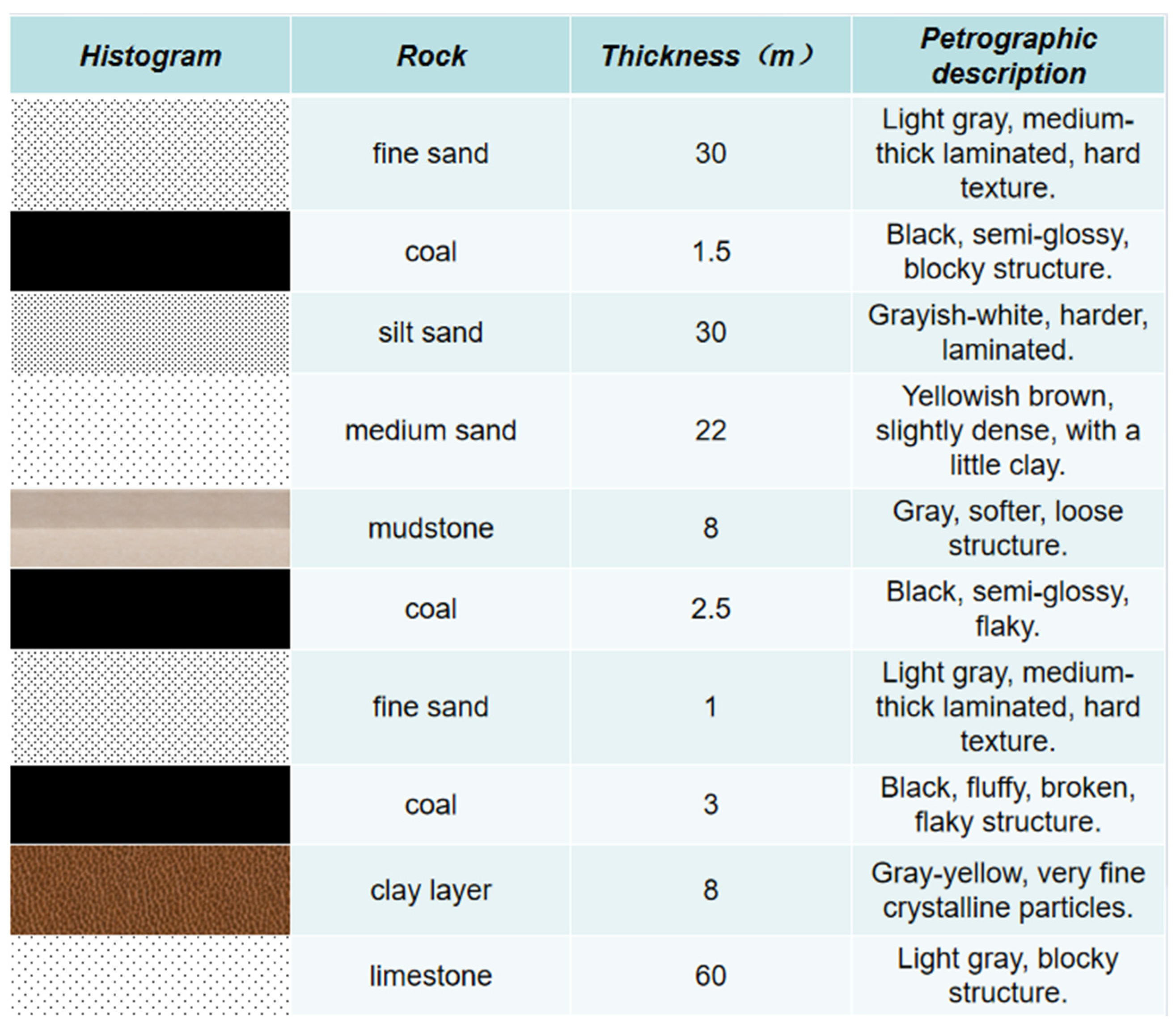
The 2500 transportation roadway is located in the 25th mining area of a mine. The coal seam is endowed between −350~−500 m, and the average depth of the roadway is 480 m. The overall direction of the coal seam is nearly east–west, with a nearly south tendency, and the tendency near the middle and the northern section is slightly west. The inclination of the coal seam in the southern part of the working face is 3°~5°, and the inclination of the coal seam in the northern part is 7°~9°. The industrial grade of the coal is long-flame coal, black, asphalt luster, shell-like fracture strip structure, and block structure. The endogenous fissure is more developed and brittle, with bright coal as the main component and dark coal as the second. Therefore, allowing the surrounding rock to creep within a certain range and releasing a certain amount of pressure not only allows for a better bearing capacity and a stronger ability to resist the deformation of the surrounding rock, but can also better cope with the effects brought about by the mining pressure. A comprehensive histogram of the coal rock is shown in Figure 2.

Figure 2.
Coal and rock composite histogram.
Due to the deeper burial of the coal seam, the original rock stress is larger, and the coal seam is subject to secondary tectonic stress. The first tectonic action is in the SW–NE direction, forming the various dorsal and vertical slopes in the area, and the second one is in the SE-NW direction, which cuts the various dorsal and vertical slopes to form a number of fractures; associated with the secondary tectonics, the formation of the two sets of joints within the seam is 45° to the tectonic direction, resulting in more severe structural damage to the coal seam. Associated with these two tectonics, two sets of joints at 45° to the tectonic direction were formed in the coal seam, resulting in serious structural damage to the coal seam and dense spacing of the joints, thus forming a weak face system favorable to the crushing of the top coal. The joints of the coal seam are shown in Table 1.

Table 1.
Coal seam jointing conditions.
3.2. Determination of the Physical and Mechanical Parameters of the Surrounding Rock
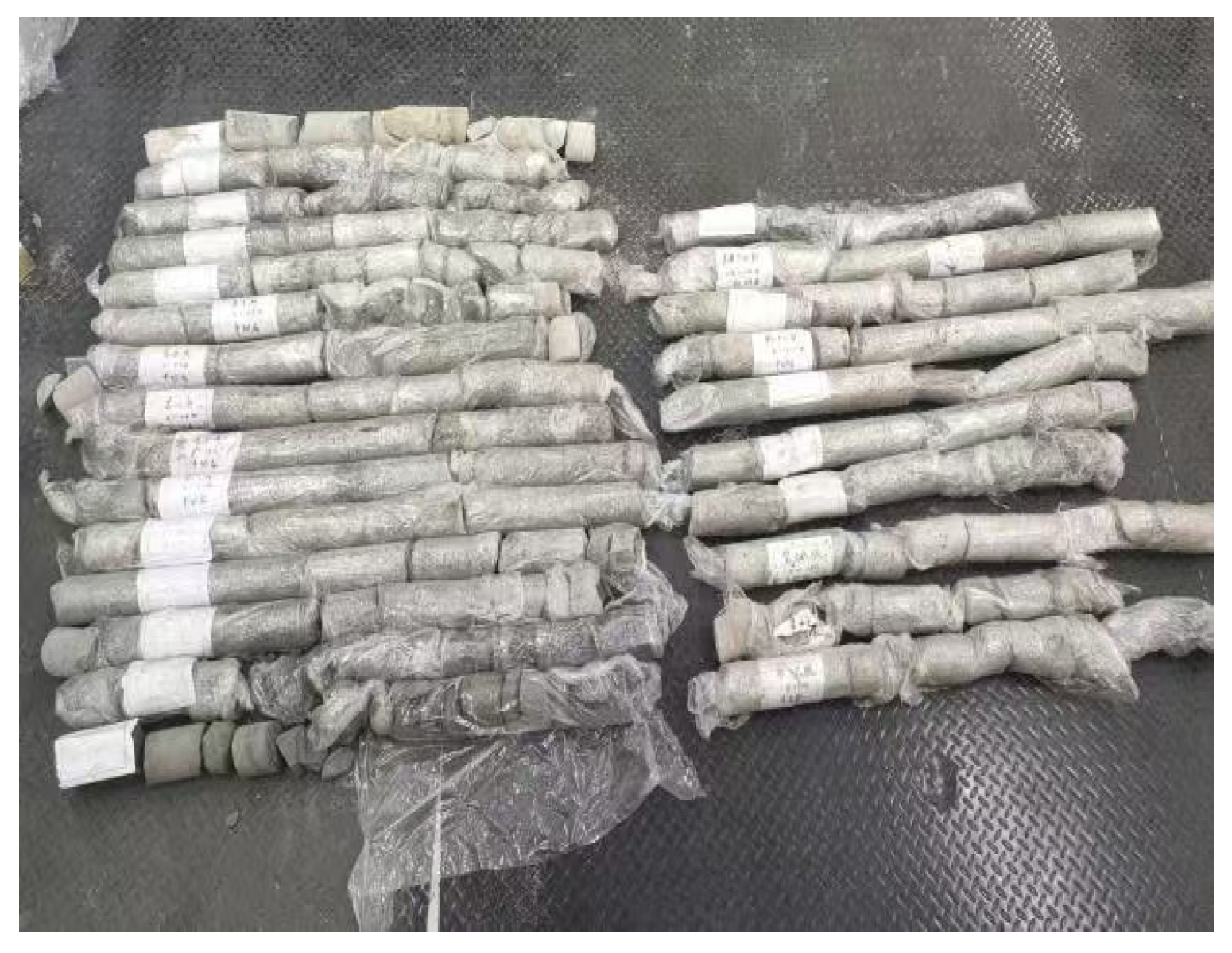
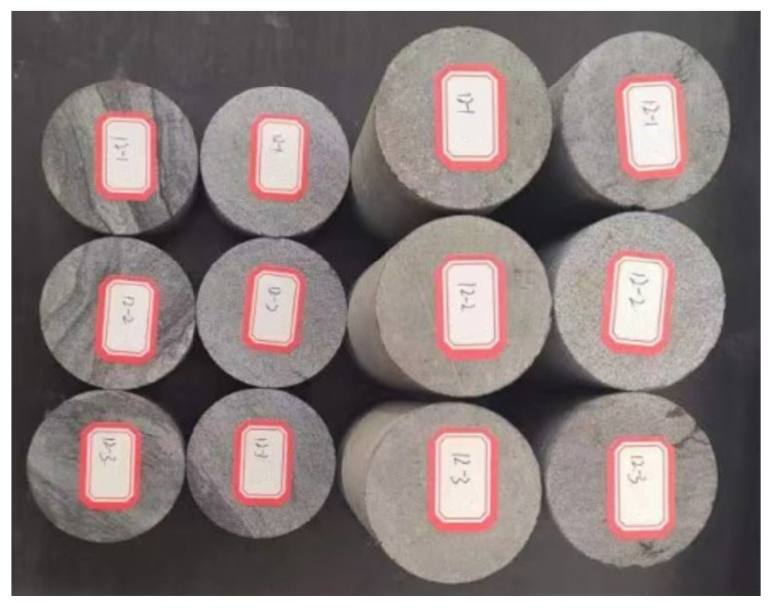
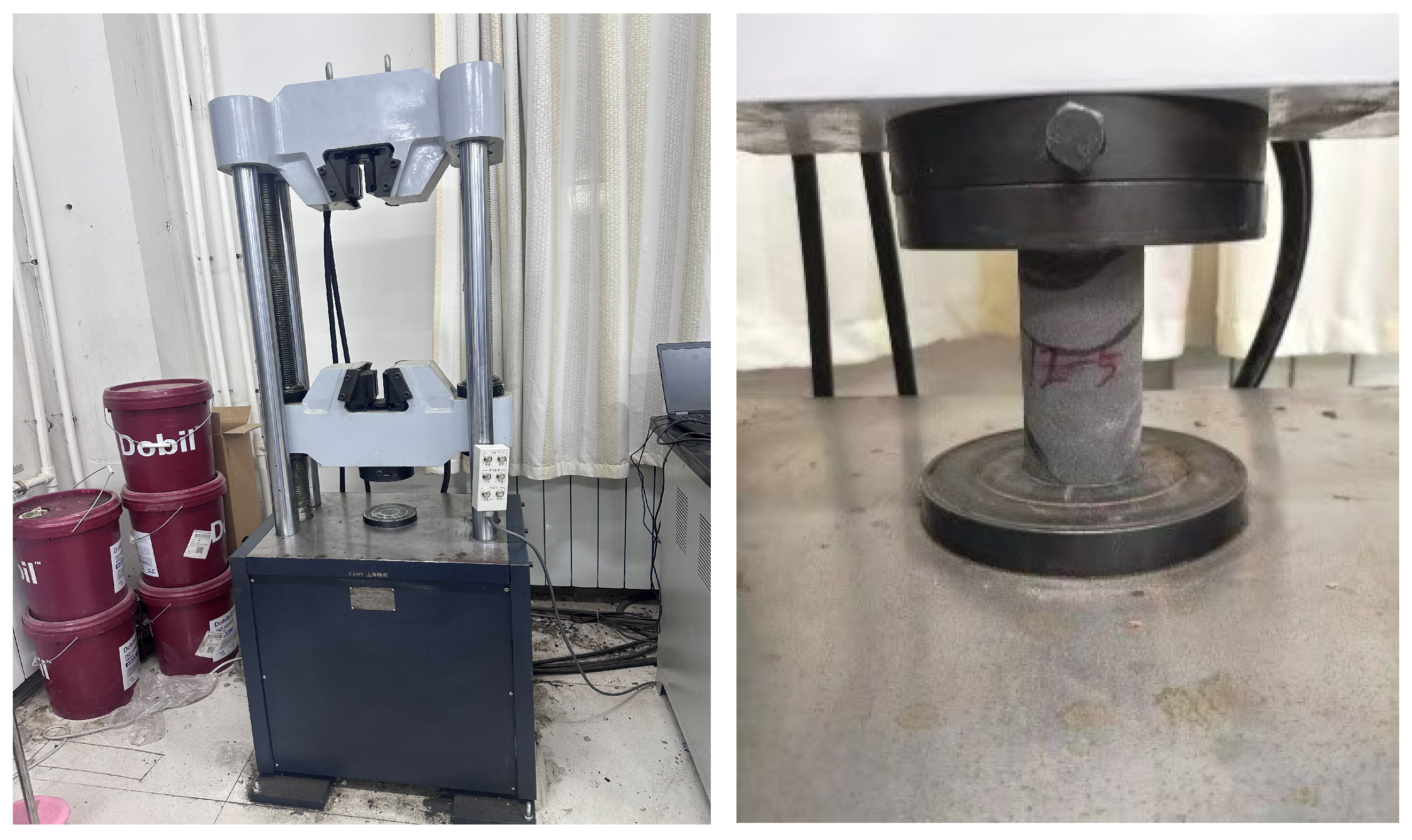
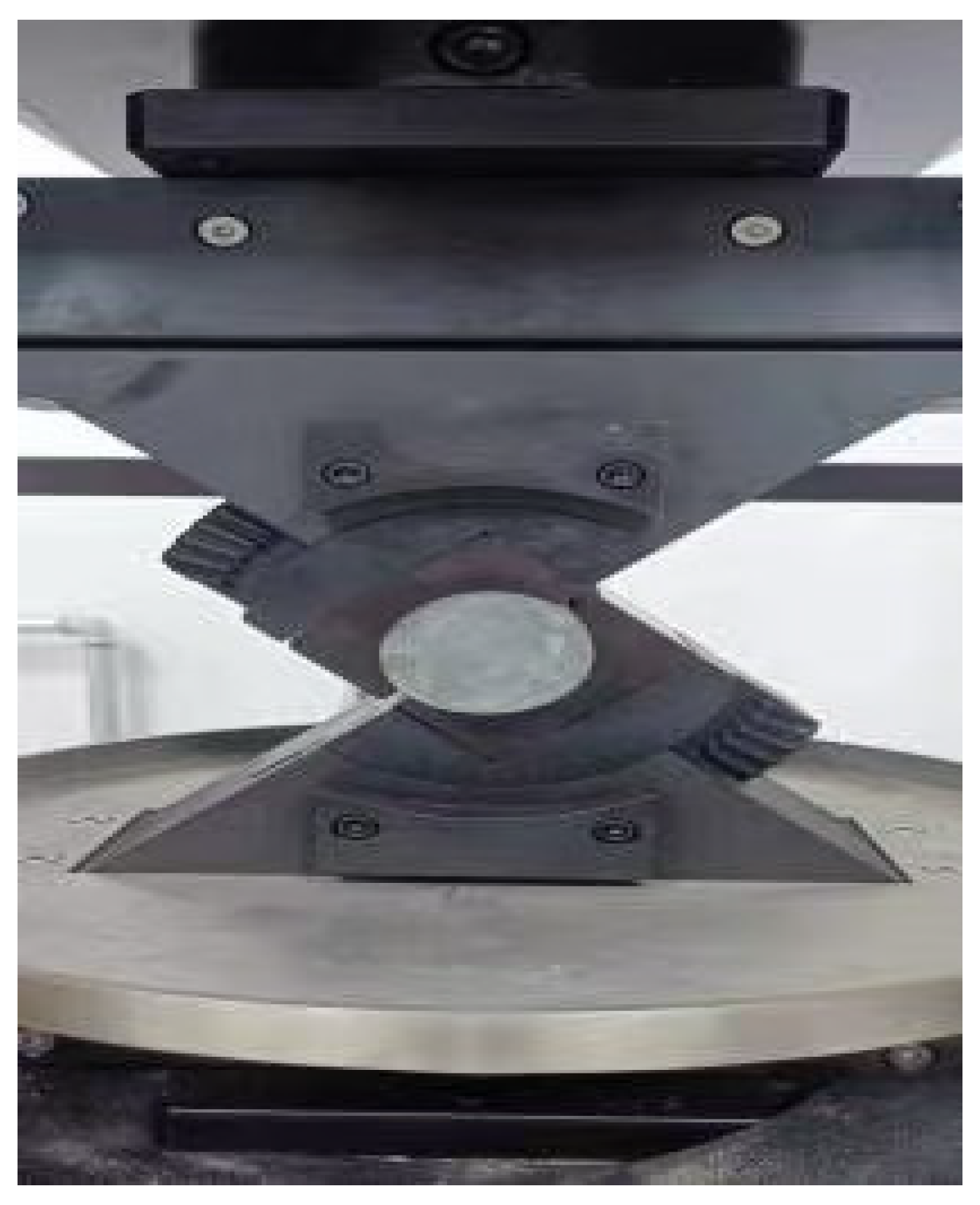
The physical and mechanical parameters of the surrounding rock are the basis for the theoretical study of underground engineering, engineering design, and construction, and are an important basis for the study of the support structure of the roadway and the stability control of the surrounding rock. According to the research needs, the 2500 transportation roadway of this mine is taken as the research object, and the top and bottom plates of the roadway are core-taken on the spot using a geological drilling machine. The drilled core samples are shown in Figure 3. The samples were sealed with cling film to be processed in the laboratory. All rock samples were cut and polished in the laboratory and finally processed into cylindrical specimens of Φ100 mm × 150 mm and Φ100 mm × 50 mm, as shown in Figure 4. Through the uniaxial compressive test, as shown in Figure 5, and shear test, as shown in Figure 6, the basic mechanical parameters, such as the uniaxial compressive strength of the peripheral rock of the roadway, were mainly determined, and the measured physical and mechanical parameters of the peripheral rock of the roadway are shown in Table 2.
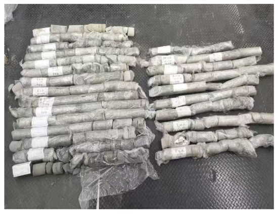
Figure 3.
Core samples drilled on site.
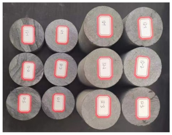
Figure 4.
Rock samples collected in the field.
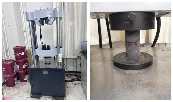
Figure 5.
Uniaxial compression test.
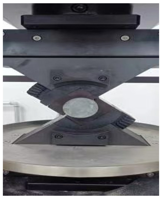
Figure 6.
Shear test.
Table 2.
Physical and mechanical parameters of the surrounding rock.
The mineral composition of rock is the main factor controlling its physical, mechanical, and hydro-physical properties, and is also an important basis for evaluating the water-bearing (isolation) performance and anti-mining deformation capacity of soft layer soil. Therefore, it is essential to determine and analyze the mineral composition of silty sandy rock and soil.
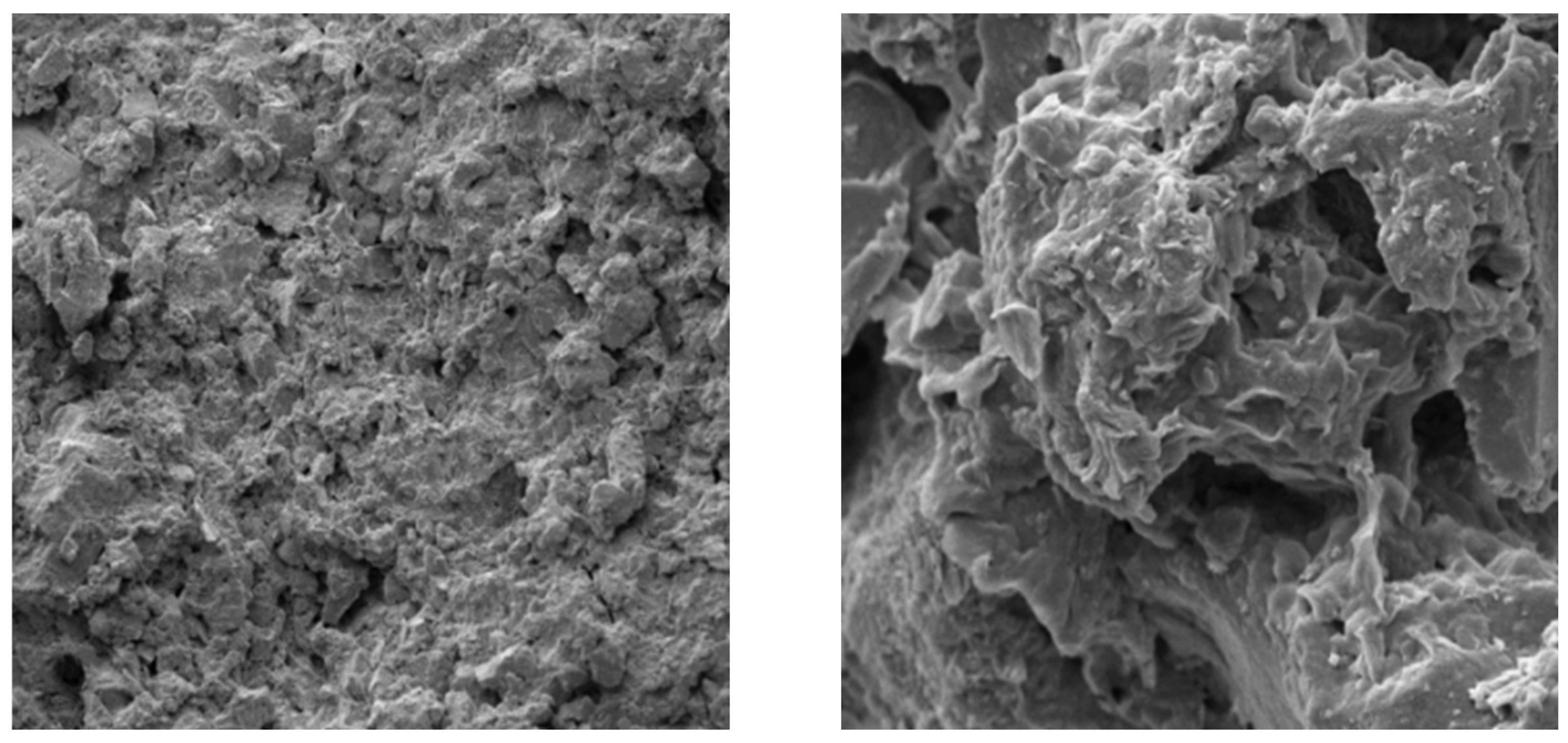
In order to analyze the internal structural characteristics of the specimens more intuitively, electron microscope scanning tests were carried out on the mudstone and sandstone samples, respectively, and the instrument model used for the SEM analysis was the Czech Republic: TESCAN MIRA LMS. The results of the scans are shown in Figure 7 and Figure 8. By observing the test results, it can be seen that the mudstone specimen is gray-black and blocky, with a relatively uniform particle size distribution, but the inter-grains are soft, with poor particle cementation and a relatively high amount of powdery sand grain. They also contain a large amount of quartz, feldspar, ilmenite, black mica, and a ilmenite mixing layer, as well as a small amount of iron oxides, calcite, monazite, barite, and other minerals. The sandstone specimen particles’ gravel diameter is small and gray–black, with good homogeneity and good cementation between the cement. In addition to the individual gravel sand gravel with an unequal gravel diameter, the other main mineral components are quartz, a montmorillonite or ilmenite mixed layer, chlorite, ilmenite, and so on.
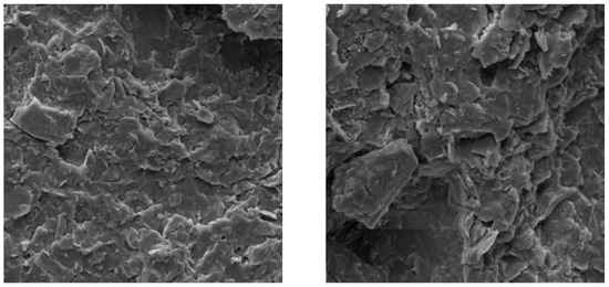
Figure 7.
Scan of the mudstone specimen.

Figure 8.
Scan of the sandstone specimen.
3.3. Numerical Modeling
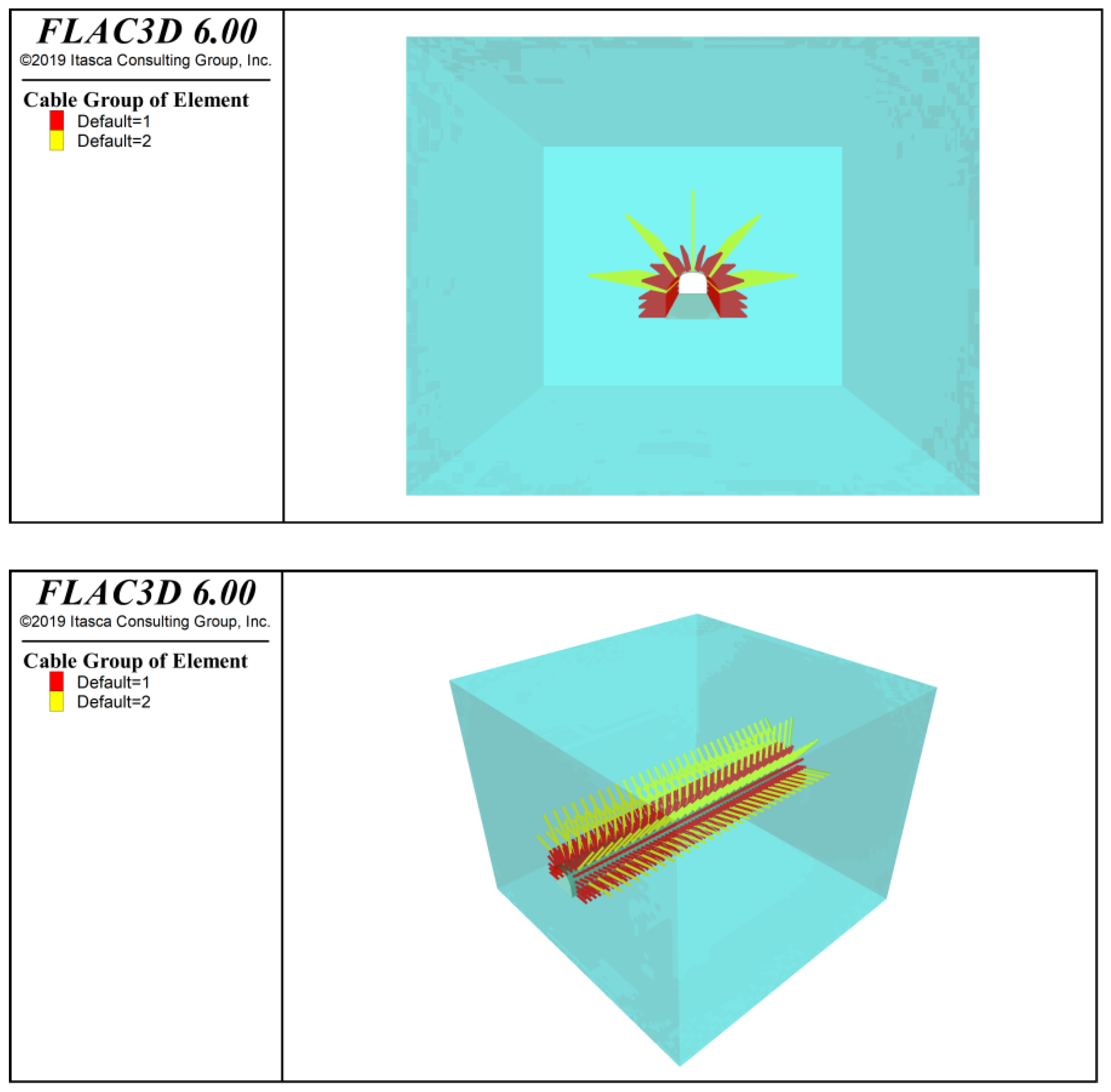
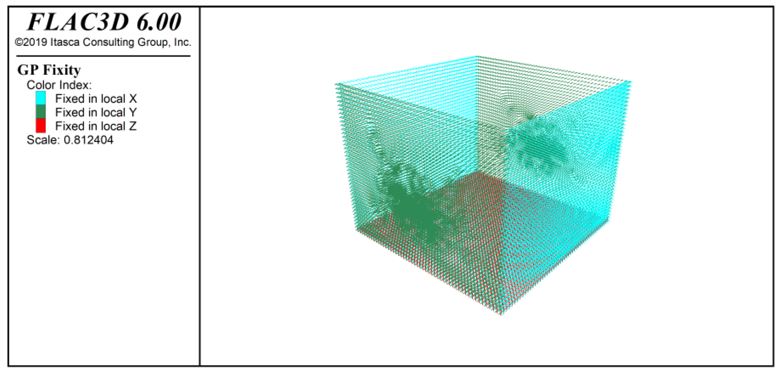
Based on the coal seam structure of the 2500 transportation roadway, the support structure is mainly made of materials, such as an anchor cable, anchor rods, steel bands, trays, and metal mesh. FLAC3D numerical simulation software (FLAC3D6.00) is used to analyze and study the problem and to establish a numerical analysis model to simulate the deformation of the surrounding rock under this support scheme. As shown in Figure 9, the model size is length × width × height = 50 m × 40 m × 45 m, and a total of 100,942 units are divided into the model, adopting the Moore–Cullen yield criterion. The model’s boundary conditions are rigid constraints at the bottom, with surrounding constraint horizontal displacement and a top stress boundary. The specific boundary conditions are shown in Figure 10.
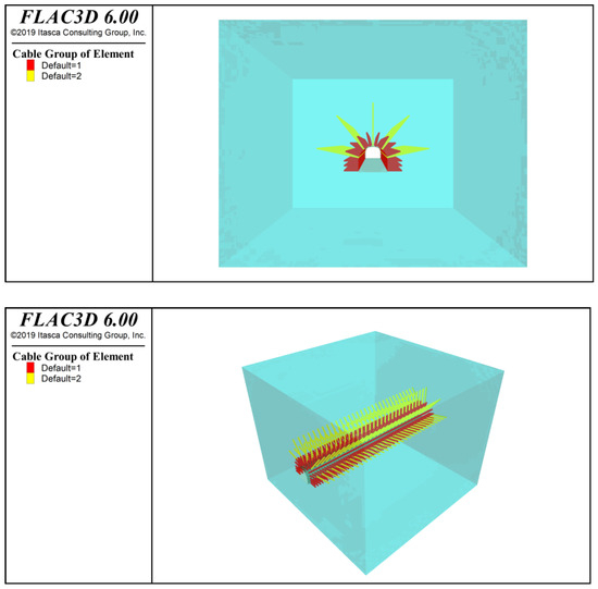
Figure 9.
Numerical analysis models.

Figure 10.
Numerical model boundary conditions.
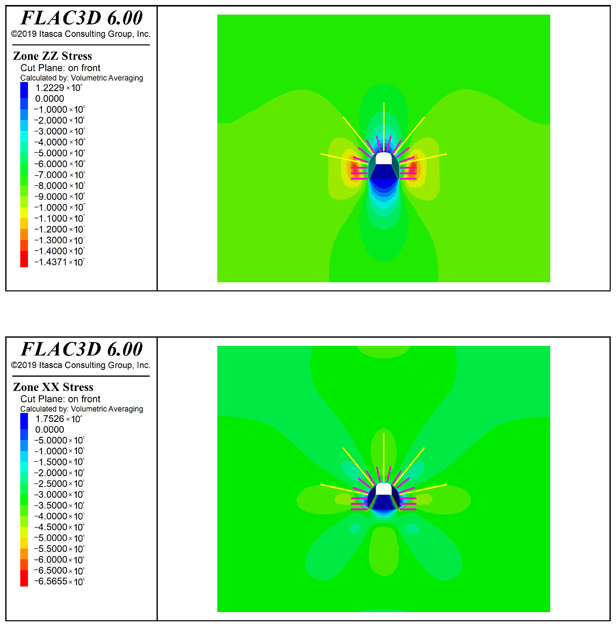
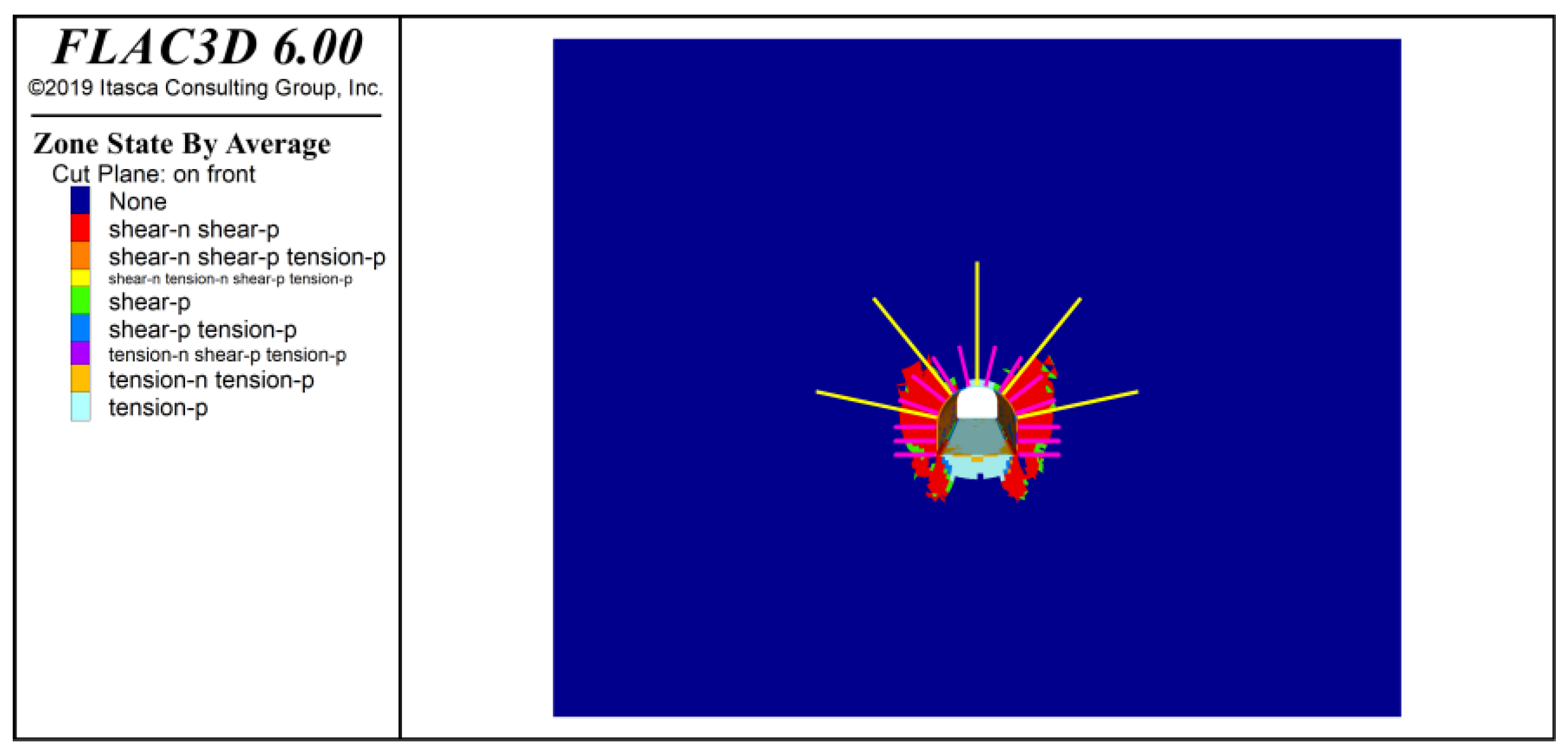
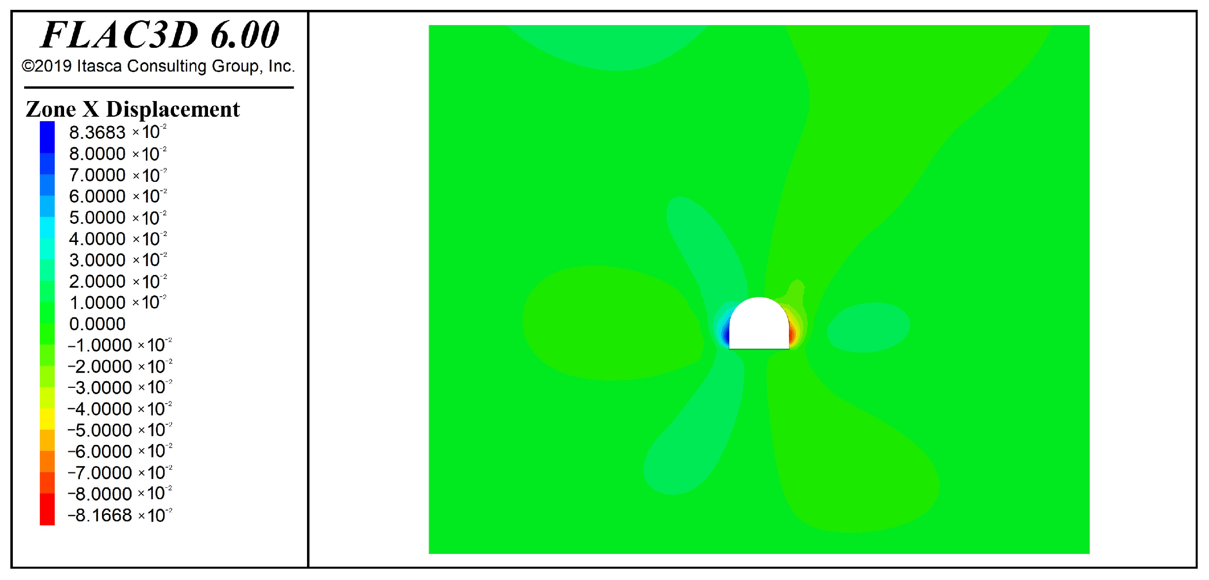
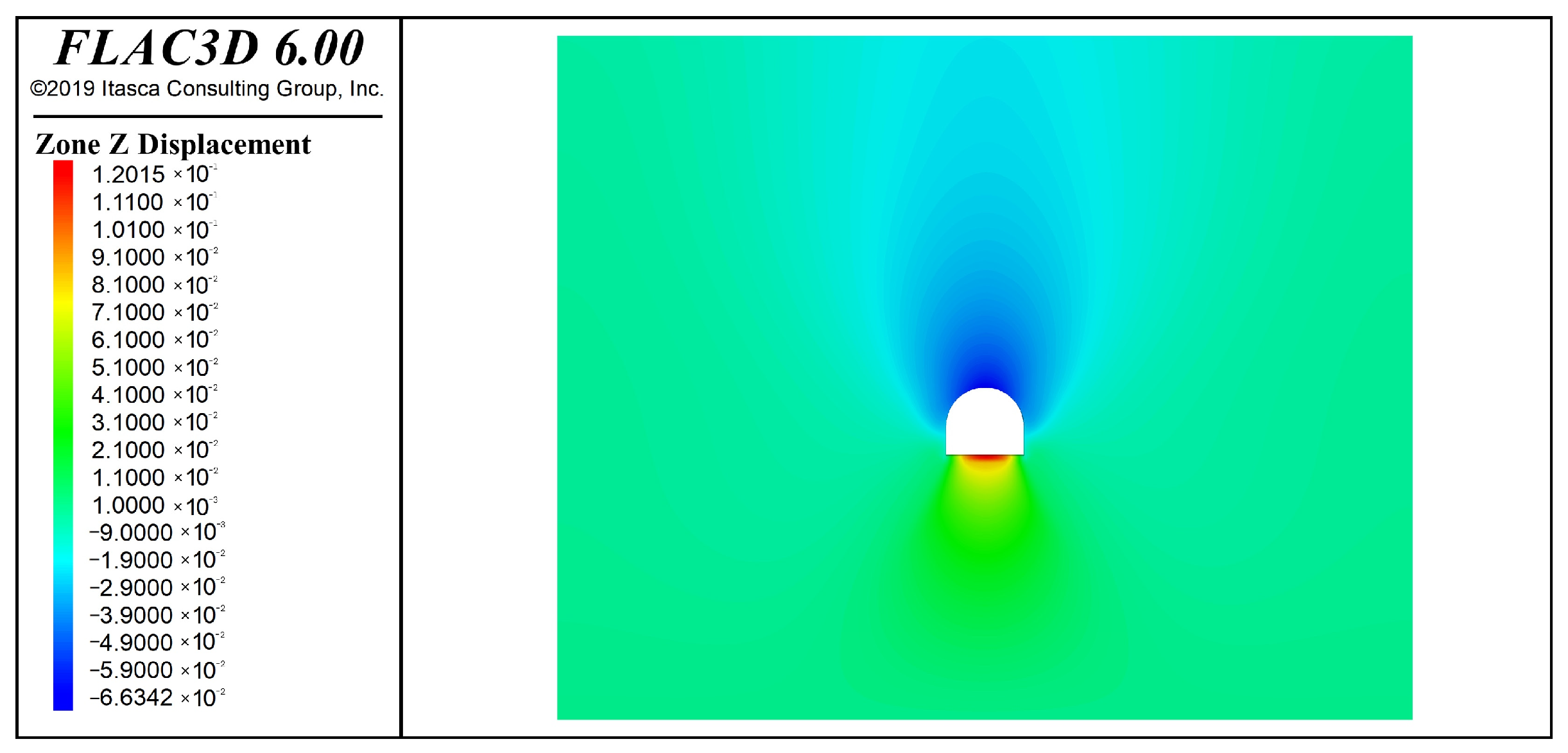
The buried depth of the roadway is 480 m. According to the ground stress calculation formula, the vertical stress of the roadway is 8.028 Mpa, and the pressure measurement coefficient is taken as 1. This stress is applied to the top and the gang part of the model, and the vertical and horizontal stresses are shown in Figure 11. The plastic zone is shown in Figure 12. The calculation results of the vertical and horizontal displacements of the roadway in the support scheme are shown in Figure 13 and Figure 14.
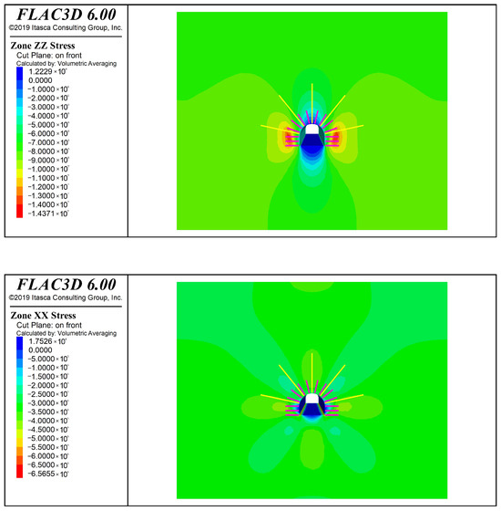
Figure 11.
Vertical and horizontal stress diagrams applied.
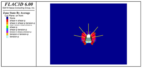
Figure 12.
Plastic zone of the surrounding rocks.
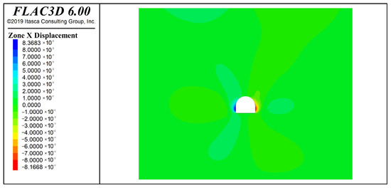
Figure 13.
Numerical simulation of the vertical deformation.
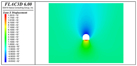
Figure 14.
Numerical simulation of the horizontal deformation.
Through the numerical simulation results, it can be seen that under this support scheme, the maximum values of roof subsidence and bottom bulge are 66.3 mm and 120 mm, respectively, while the total displacement is about 180 mm, and the displacement of the two gangs is about 165 mm. In summary, the numerical analysis results show that the support program can effectively control the deformation of the tunnel perimeter rock.
4. Roadway Support Program Design
The surrounding rock of the 2500 transportation roadway is soft and broken, with a large burial depth, high ground stress, and strong expansion, and the joints, fissures and laminations of the coal seam in this working face are developed. The seam is a soft rock coal seam. Its deformation is mainly characterized by fragmentation and expansion, and this deformation is characterized by the expansion of clay minerals after water absorption and disintegration and expansion after weathering and water loss. Both sides of the roadway have a large contraction and a serious bottom drum. According to the characteristics of the surrounding rock of the roof and bottom plate of the roadway, the support of this transportation roadway adopts the joint support method of anchor rods + anchor ropes + a 36U steel metal support + a laying net + laying mats + filling behind the wall (thickness of 300 mm concrete), and adopts the combination of permanent support + over-supporting + reinforcing support in terms of the support.
4.1. Design of Permanent Support Parameters
The permanent support is in the form of anchor rods + anchor cables.
- (1)
- The formula for calculating the total length of the anchor is as follows:
After calculation, the value of L is 1.12 m. The actual anchor of the working face is 2.4 m long, which is larger than the calculated value, and the length of the anchors used in the design meets the calculation requirements.
- (2)
- The spacing between rows of anchors is calculated as follows.
According to the suspension theory, the anchor anchoring force should be able to bear the weight of the rock body suspended by the anchor, i.e., as follows:
where is the anchor bar anchoring force (take 100 kN/root). is the safety factor (take 2) and is the row spacing between anchors.
After calculating the inter-row spacing of the anchors, a = 3.8 m, so the spacing of anchors was designed to be 0.8 m, and the row spacing was 0.8 m, which was less than 3.8 m to meet the calculation results.
- (3)
- The formula for calculating the total length of the anchor cable is as follows:
The length of the anchor cable going deeper into the more stable rock formation is determined by the following formula:
where is the safety factor (take 2). is the anchor diameter (take 28.6 mm). is the anchor cable tensile strength (take 1860 N/mm2). is the adhesion strength of the anchor cable to the anchoring agent (take 10 N/mm2).
The calculated length of anchor cable should be greater than or equal to 6.11 m. The length of anchor cable selected in the actual project is 7.3 m. The length of anchor cable selected in the design meets the calculation requirements.
- (4)
- Suspension theory was used to calculate the row spacing between anchor cables using the following formula:
After calculation, the distance between the rows of anchor cables is 2.7 m, while the distance between the rows of anchor cables is designed to be 1.6 m, which is less than 2.7 m and meets the support requirements.
4.2. Overhead Support and Reinforced Support
The face of the working face is arranged with equal strength anchors, and the face is maintained by using pallets with wooden plates. The 4.6 m clear width roadway is designed to construct one 2.4 m overhead support anchor on each side of the working face at 70° upward along the digging direction in each cycle. The row spacing between the anchors is 1.6 m × 1.6 m, and the anchor type is an MSGLD400/22 equal-strength all-threaded anchor, with a diameter of Φ22 mm, yield strength of 400 MPa, and a CKb2370 anchoring agent. The structure of the roadway support is shown in Figure 15.
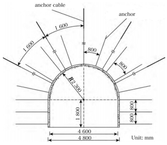
Figure 15.
Roadway support structure diagram.
The means of strengthening support adopts the combination mode of a metal bracket + hanging net + concrete filling behind the wall (or shotcrete), and the anchors outside the shed and the locking leg anchors and center pillars are used as a reinforcement support. The support design, according to the different geological conditions and changes, such as in the case of broken perimeter rock, tectonic zone, dynamic pressure zone, etc., increase the top of the gang anchor rods, allow for timely playing of the anchor cable, and provide follow up for the shelf shed support.
4.3. On-Site Monitoring of Perimeter Rock Deformation
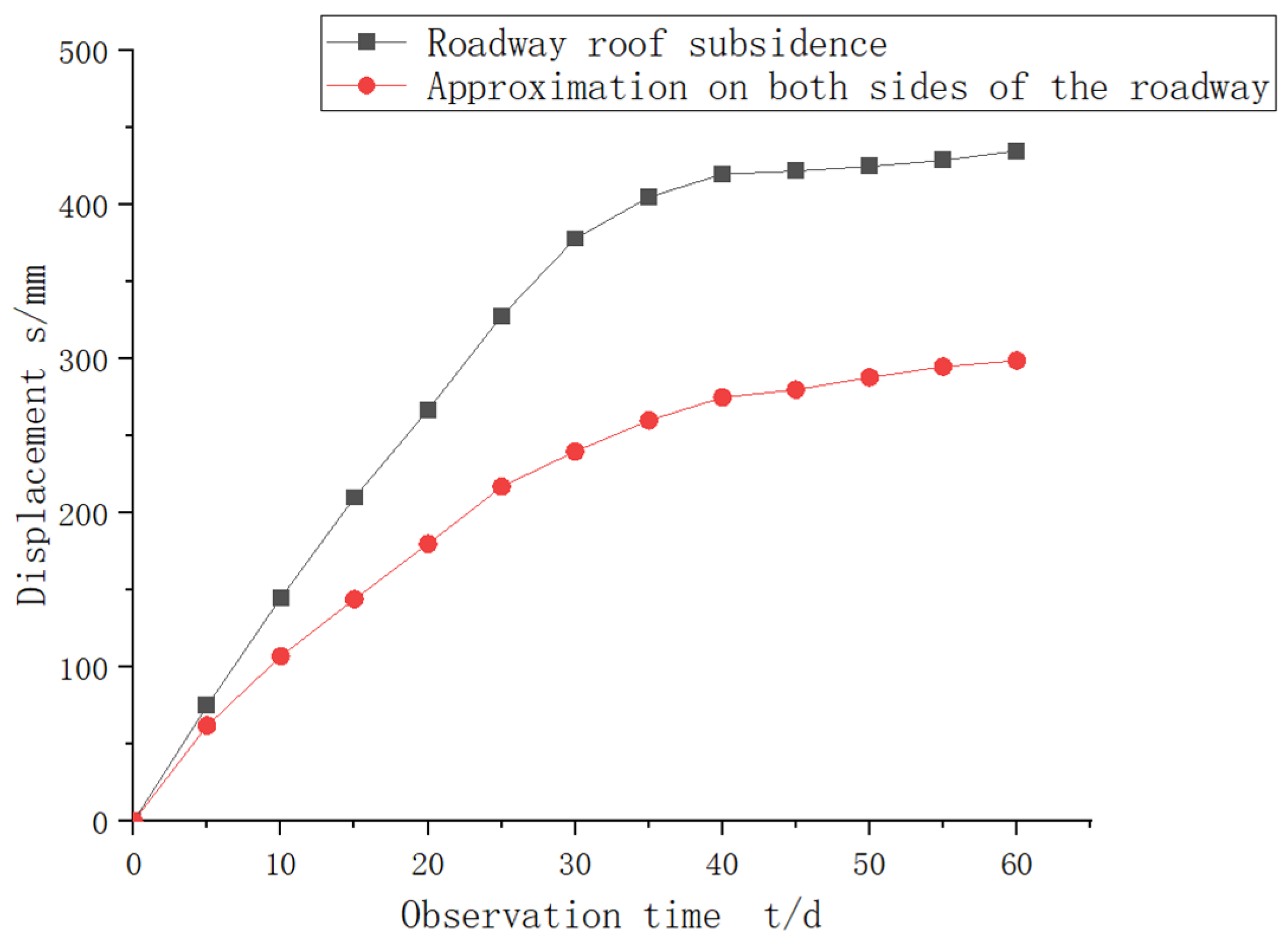
The amount of roof subsidence and the amount of approach to both sides of the roadway can reflect the deformation and movement of the surrounding rock, determine the stability of the surrounding rock, and evaluate the supporting effect and adaptability of the supporting structure of the comprehensive mining face. In China, within the roof control range of a comprehensive mining face, the amount of roof subsidence is generally required to be no greater than 100 mm per meter of mining height, so it will be strictly monitored and controlled to ensure that it does not exceed the safety limit. As can be seen from Figure 16, the maximum value of the roof subsidence of the roadway is 455 mm, and the maximum value of the displacement of the two sides of the roadway is 303 mm. It can be seen that the overall deformation of the roadway is within the permissible range, and the technical solution proposed in this paper can control the stability of the perimeter rock of the roadway. Although the displacement has tended stabilize, it should also be strictly monitored and controlled to ensure that it does not exceed the safety limit during the construction and maintenance of the roadway due to the long-term effects of the mining. Monitoring and control are essential to ensure that it does not exceed the safety limit.
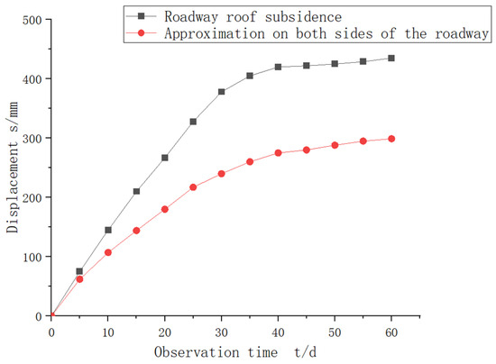
Figure 16.
Deformation curves for perimeter rock monitoring.
5. Conclusions
This paper takes the 2500 transport roadway of the 25th mining area of a mine as the engineering background, analyzes the destabilization mechanism of the roadway perimeter rock, analyzes the deformation of the perimeter rock of the deep roadway, determines the physical and mechanical parameters of the perimeter rock using indoor tests, simulates them using numerical analysis software, and proposes the roadway perimeter rock support scheme. The main conclusions are as follows:
- (1)
- The rupture and delamination of the rock layer are the main reasons for the damage to the roadway roof, and the elastic–plastic deformation of the surrounding rock has been completed shortly after digging in order to stop further deformation of the surrounding rock. This requires a suitable support timing and support program. Allowing the perimeter rock to creep within a certain range and releasing a certain amount of pressure not only results in a better bearing capacity and stronger resistance to perimeter rock deformation, but also allows the rock to better cope with the impact of mining pressure.
- (2)
- Using the rock samples taken from the site, the samples were subjected to an electron microscope scanning test and indoor triaxial test to obtain the physical and mechanical parameters of the surrounding rock of the roadway, and to establish a numerical model to calculate the maximum values of the roof subsidence and bottom bulge of the roadway. These values were found to be 66.3 mm and 120 mm, respectively, while the total amount of approximation was found to be about 180 mm, and the amount of approximation of the two gangs was found to be about 165 mm. The joint support program of an anchor rod + anchor cable + 36U steel metal support + netting + matting + backwall filling is proposed.
- (3)
- The displacement of the surrounding rock of the roadway is regularly monitored by the digital convergence meter, and the displacement of the surrounding rock of the roadway is obtained after the roadway is excavated and under the influence of mining. The maximum value of roof subsidence is 455 mm, and the maximum value of the two sides of the roadway is 303 mm. There are obvious convergence characteristics, and the support program can effectively control the deformation and damage of the surrounding rock.
Author Contributions
G.L.: Data curation, Conceptualization, Writing—original draft. Y.Y.: Methodology, Review and editing, Supervision, Funding acquisition. All authors have read and agreed to the published version of the manuscript.
Funding
This research received no external funding.
Institutional Review Board Statement
Not applicable.
Informed Consent Statement
Not applicable.
Data Availability Statement
The original contributions presented in the study are included in the article, further inquiries can be directed to the corresponding author. This research received no external funding.
Conflicts of Interest
The authors declare no conflicts of interest.
References
- He, M.; Xie, H.; Peng, S.; Jiang, Y. Study on rock mechanics in deep mining engineering. Yanshilixue Yu Gongcheng Xuebao/Chin. J. Rock Mech. Eng. 2005, 24, 2803–2813. [Google Scholar]
- Kang, H.; Fan, M.; Gao, F.; Zhang, H. Deformation and support of rock roadway at depth more than 1000 meters. Chin. J. Rock Mech. Eng. 2015, 34, 2227–2241. [Google Scholar]
- Yu, W.; Wang, W.; Huang, W.; Wu, H. Deformation mechanism and rework control technology of high stress and soft rock roadway. J. China Coal Soc. 2014, 39, 614–623. [Google Scholar]
- Zhao, C.; Li, Y.; Liu, G.; Huang, S. Study on surrounding rock support technology of deep soft rock roadway. Coal Sci. Technol. 2022, 50, 76–84. [Google Scholar]
- Ren, S.; Li, Z.; Zhou, W. Research on supporting technology of broken roof roadway in loose coal seam of coal mine. China Energy Environ. Prot. 2022, 44, 39–44. [Google Scholar]
- He, M. Latest progress of soft rock mechanics and engineering in China. J. Rock Mech. Geotech. Eng. 2014, 6, 165–179. [Google Scholar] [CrossRef]
- Guo, H.; Chen, X.; He, M.; Xi, S.; Tang, J. Frictional contact algorithm study on the numerical simulation of large deformations in deep soft rock tunnels. Min. Sci. Technol. 2010, 20, 524–529. [Google Scholar] [CrossRef]
- Gao, M.; Zhao, Y.; Li, M. Roof and support and bottom yielding support with whole section and O-shape control principle for soft rock roadway and engineering practice. Rock Soil Mech. 2014, 35, 2307–2313. [Google Scholar]
- He, M.; e Sousa, R.L.; Müller, A.; Vargas, E., Jr.; e Sousa, L.R.; Chen, X. Analysis of excessive deformations in tunnels for safety evaluation. Tunn. Undergr. Space Technol. 2015, 45, 190–202. [Google Scholar]
- Huang, M.; Zhou, Z.; Huang, Y.; Ou, J. A distributed self-sensing FRP anchor with built-in optical fiber sensor. Measurement 2013, 46, 1363–1370. [Google Scholar] [CrossRef]
- Huang, M.H.; Zhou, Z.; Ou, J.P. A novel durable intelligent fiber reinforced polymer anchor with embedded optical fiber Bragg grating sensors. Sci. China Technol. Sci. 2012, 55, 1455–1462. [Google Scholar] [CrossRef]
- Lai, L. Study on the overburden movement and ore pressure manifestation law of large-scale mining and high comprehensive mining surface. China Coal 2022, 48, 125–131. [Google Scholar]
- Liu, J. Study on the ore pressure law of thick coal seam comprehensive surface. Energy Technol. Manag. 2022, 47, 114–116. [Google Scholar]
- Huang, Q. Study on the movement law of overburden mining with large inclination angle. Coal Technol. 2019, 38, 39–43. [Google Scholar]
- Xu, H. Study on the law of ore pressure display in the working face with large inclination angle. China Min. Mag. 2022, 31, 102–109. [Google Scholar]
- Liu, J.; Dong, G. Study on the breaking law of roof of extra thick loose overlying coal mining face. Shanxi Coking Coal Sci. Technol. 2013, 37, 10–12+15. [Google Scholar]
- Jarred, D.J.; Haberfield, C.M. Tendon/grout interface performance in grouted anchors. In Ground Anchorages and Anchored Structures; Thomas Telford: London, UK, 1997. [Google Scholar]
- Stillborg, B. Experimental Investigation of Steel Cables for Rock Reinforcement in Hard Rock. Ph.D. Thesis, Lulea University of Technology, Luleå, Sweden, 1984. [Google Scholar]
- Goto, Y.; Obata, M.; Maeno, H.; Kobayashi, Y. Failure mechanism of new bond-type anchor anchor bolt subject to tension. J. Struct. Eng. 1993, 119, 1168–1187. [Google Scholar] [CrossRef]
- Cook, R.A. Behavior of chemically bonded anchors. J. Struct. Eng. 1993, 119, 2744–2762. [Google Scholar] [CrossRef]
- Obata, M.; Inoue, M.; Goto, Y. The failure mechanism and the pull-out strength of a bond-type anchor near a free edge. Mech. Mater. 1998, 28, 113–122. [Google Scholar] [CrossRef]
- Bylapudi, G. Corrosion of Rock Anchors in US Coal Mines. Master’s Thesis, Southern Illinois University at Carbondale, Carbondale, IL, USA, 2010. [Google Scholar]
- Zhang, G. Study on the law of roof collapse of the 3207 large mining height working face of Shanxi Holsinghe Coal Mine. Zhongzhou Coal 2016, 20, 68–70. [Google Scholar]
- Wang, H. Numerical analysis of the first collapse of the roof of the coal mining face. Energy Sci. Technol. 2022, 20, 22–27. [Google Scholar]
- Li, Z.; Wang, F.; Tian, B.; Wu, J.; Jing, L.; Zhang, H. Numerical simulation study on support technology of soft rock roadway in Daliu Coal Mine. China Coal 2022, 48, 20–26. [Google Scholar]
- Lin, T.; Liu, S.; Wang, M. Research on surrounding rock control technology of soft rock roadway based on combined support with O-type arch. China Coal 2015, 22, 60–63. [Google Scholar]
- Li, C.; Zhao, Y.; Zhang, J.; Ma, W.; Deng, X. Research on Control Mechanism and Supporting Technology of Peripheral Rock in Deep Soft Rock Roadway; China University of Mining and Technology Publishing House: Xuzhou, China, 2020; Volume 4, pp. 8–12. [Google Scholar]


Disclaimer/Publisher’s Note: The statements, opinions and data contained in all publications are solely those of the individual author(s) and contributor(s) and not of MDPI and/or the editor(s). MDPI and/or the editor(s) disclaim responsibility for any injury to people or property resulting from any ideas, methods, instructions or products referred to in the content. |
© 2024 by the authors. Licensee MDPI, Basel, Switzerland. This article is an open access article distributed under the terms and conditions of the Creative Commons Attribution (CC BY) license (https://creativecommons.org/licenses/by/4.0/).