Featured Application
Test plan creation for automated vehicles to assess the vehicles prior to public road testing and deployment.
Abstract
The growing complexity of autonomous vehicle functionalities poses significant challenges for vehicle testing, validation, and regulatory approval. Despite the availability of various testing protocols and standards, a harmonized and widely accepted method specifically targeting the selection of critical test scenarios—especially for safety assessments prior to public road testing—has not yet been developed. This study introduces a systematic methodology for selecting a minimum critical set of test scenarios tailored to an autonomous vehicle’s Operational Design Domain (ODD) and capabilities. Building on existing testing frameworks (e.g., EuroNCAP protocols, ISO standards, UNECE and EU regulations), the proposed method combines a structured questionnaire with a weighted cosine similarity based filtering mechanism to identify relevant scenarios from a robust database of over 1000 test cases. Further refinement using similarity metrics such as Euclidean and Manhattan distances ensures the elimination of redundant test scenarios. Application of the framework to real-world projects demonstrates significant alignment with expert-identified cases, while also identifying overlooked but relevant scenarios. By addressing the need for a structured and efficient scenario selection method, this work supports the advancement of systematic safety assurance for autonomous vehicles and provides a scalable solution for authorities and vehicle testing companies.
1. Introduction
In the past decade, as a result of the explosive growth in technology solutions, the automotive industry has undergone significant changes, resulting in the creation of highly automated functions meant to enhance traffic safety. However, the emerging systems pose serious challenges for professionals involved in vehicle testing and validation, as well as for the development of appropriate homologation procedures [1]. While previously, for more classical safety or assistance systems, test specifications consisted of a finite number of well-defined test cases, nowadays, for increasingly complex automation systems, the number of potential test cases has increased significantly. For example, in the past, testing an Electronic Stability Control (ESC) or Anti-lock Braking System (ABS) might have involved completing 10–15 test runs. Nowadays, defining test plans for certain Advanced Driver Assistance System (ADAS) functions could require over 50 or even more than 100 runs, especially in well-known assessment programs like European New Car Assessment Programme (EuroNCAP) active safety testing. The number of test runs required shows exponential growth. In the case of autonomous vehicles or Automated Driving Systems (ADS), an infinite number of traffic situations could easily generate thousands of relevant test scenarios in which the vehicle will have to perform adequately.
For autonomous vehicles, there are not yet any universally accepted regulations; their development is still taking place intensively within various working groups, such as at the UN and the EU [2,3]. Although there are various concepts for the appropriate selection of test cases, a unified procedure, especially with regard to the type approval of autonomous vehicles, has not yet been developed. Beyond type approval, other aspects such as liability, legislative issues or even interior designs, and necessary human–machine interfaces are not yet regulated or standardized [4].
One key milestone is the emergence of the New Assessment/Test Method for Automated Driving (NATM) document, which outlines a new test methodology for autonomous vehicles, relying on six main pillars, one of which is the possibility of generating a test scenario catalog [2]. The methodology is largely based on the methods established during the Pegasus project, according to which the concept of test scenarios has different contents and representations throughout the development process. The conceptual phase describes scenarios at a high level in natural language, while technical development and test scenario generation require representation with parameter spaces. The execution and evaluation of test scenarios require precisely defined cases in common data formats, which can be broken down into three levels of abstraction: functional, logical, and concrete [5].
Building on the work described in the above-mentioned studies, Regulation No. 171 was also developed, among others, which includes specific test cases for vehicles with higher levels of automation but allows for much greater flexibility in their exact definitions compared to the previous ADAS regulations, where both the manufacturer and the designated technical service such as Testing, Inspection, and Certification (TIC) companies play an important role. The regulation introduces requirements against Driver Control Assistance Systems (DCAS) including several basic test scenarios to which various more complex optional scenarios could also been defined [6]. These scenarios, among others, are also part of our utilized scenario database presented in the following sections.
In the EU, Implementing Regulation 2022/1426 outlines guidelines and proposals for testing autonomous vehicles. When developing test scenarios, it is important to select cases that are adapted to the Operational Design Domain (ODD). An interesting point is that the regulation suggests incorporating existing test scenarios into the catalog (e.g., from EuroNCAP) if they are well suited to a particular circumstance. The regulation has already been used in a Proof of Concept (PoC) project, in which it was determined that the currently available ADS solutions still have limitations that complicate their deployment into real-world traffic [7].
At the national level, Germany stands out as an example where the legal regulations allow for the type approval of ADS, but here again, the definition of appropriate test cases to fit the ODD is partly the responsibility of the manufacturer and the TIC companies, with no specific list of test cases that must be followed mandatorily [8].
The testing of ADAS functions and autonomous vehicles is increasingly incorporating various simulations, in addition to on-road testing. The latter is not foreign to more classical vehicle testing methods; however, while a comprehensible amount of so-called ‘field test’ kilometers were previously required, testing autonomous vehicles would necessitate billions of kilometers [9]. With the advancement of simulations, the time required for actual testing can be significantly reduced. However, examining the authenticity of simulations, the validation processes present particular challenges, and there are also few guidelines regarding their use in homologation [2,3,10,11]. Of course, simulations have many well-known benefits, such as implementing scenarios that would be difficult to reproduce in reality, or even the capability to run faster than real time and cost efficiency, but they also serve well in selecting the right test cases that later need to be evaluated under real-world conditions [12,13]. In simulation technologies, mixed reality technologies are becoming increasingly widespread. These technologies utilize the interactions of digital twins of both the proving ground and the test scenario participants. Among the most advanced methods are those where this integration can occur in real time, such as in various Vehicle-in-the-Loop (ViL) or Scenario-in-the-Loop (SciL) procedures [14]. The cyber–physical representation of the proving ground has become more widely accepted, and therefore more proving grounds are making Ultra-High Definition (UHD) resolution digital twins available before physical testing is conducted. This trend can be observed in several places, such as M-City (Ann Arbor, MI, USA) or even ZalaZONE (Zalaegerszeg, Hungary) being available within MATLAB/MathWorks® software environments [15].
Beyond simulation and public road testing, closed, secure test tracks continue to play a key role in the examination of autonomous vehicles and will continue to do so [16]. During proving ground trials, test scenarios for autonomous vehicles can be defined and categorized in several ways, for example, by considering safety or comfort aspects, as well as adjusting to the planned operational domain of the vehicle. For autonomous vehicles, it is also necessary to properly define the ODD and the vehicle’s responses to objects encountered within the ODD, known as Object and Event Detection and Response (OEDR). There are already standardized approaches to adequately describing the ODD, such as those by the Society of Automotive Engineers (SAE) or British Standards Institution (BSI), but even in this area, there is not necessarily a unified terminology for ODD elements and related concepts [17]. The definition of the ODD is an iterative process that should preferably be carried out in the relatively early stages of designing the autonomous function, but it may also be necessary to go back and refine certain attributes during the testing process, or even define new characteristics that were not anticipated earlier [18].
In the field of scenario generation for testing ADS, numerous scientific methods and technologies have been developed to address the growing demand for testing safe, energy-efficient, high-performance vehicle control strategies. The common approach in these methods is to enhance the efficiency of the testing process and accurately simulate real-world traffic situations. These methods often employ adaptive techniques that can adjust to environmental changes in real time, as well as reinforcement learning and optimization algorithms to identify and manage critical scenarios. Data-driven approaches and high-fidelity simulations also play a central role, ensuring that the widest range of relevant scenarios is examined during testing [19,20,21,22,23,24].
Based on the reviewed literature, it is apparent that although there are several well-utilizable approaches for both the selection of test cases and the proper definition of the ODD, none really address how to compile a collection of test cases tailored to a given autonomous function or vehicle with a relatively small number of already accepted test cases. Such a collection would allow for a high level of certainty in determining the safety level of the vehicle in critical cases, which could facilitate the efficiency of pre-deployment inspections aimed at testing purposes. In the everyday work of a TIC company, alongside the detailed and extensive testing campaigns aimed at discovering any misbehavior and conducting thorough inspections, it is also crucial to assess the vehicles before public road testing or deployment. This assessment ensures that we identify any potential issues early on. Therefore, a more generic method must be developed to provide a clear picture of the vehicles’ readiness and general safety.
In this article, we present a method that allows for the definition and selection of test cases for an autonomous vehicle to test safety-critical situations in a test track environment. Our primary objective was to develop a test planning methodology based on existing regulatory-based scenarios. Although there are currently few standardized or regulatory test cases specifically designed for autonomous vehicles, many ADAS functions share significant similarities with automated driving features—both technologically and in terms of test conditions. Therefore, we also used established ADAS test cases as a starting point. Our intention was to work with industry-accepted scenarios rather than generate entirely new ones, which would require extensive parameterization and result in a large number of test cases—making the process both time-consuming and costly.
In our work, we also define a set of preliminary input parameters gathered through a questionnaire, which allows us to select the appropriate cases for the given vehicle to conduct the aforementioned tests. The method developed in this way can be particularly well utilized for pre-deployment safety checks before releasing road vehicles for either operational or testing purposes in traffic, for which different authorities and TIC companies currently do not have harmonized, effective solutions. Since such test plans are often created in an ad hoc manner, relying heavily on engineering intuition and experience, we aimed to provide a more systematic and scientifically grounded selection process. This motivation led to the development of the methodology presented in our paper.
The structure of this work is as follows: In the Section 2, the developed methodology is presented, including the creation of a comprehensive test run database and the development and use of a structured questionnaire. In the Section 3, the applicability of the method is demonstrated using real-world projects, and the alignment of the selected scenarios with previous test plans is analyzed. Finally, in the Section 4, the findings are critically evaluated in the context of existing studies, and recommendations for future research and development are presented.
2. Materials and Methods
In the following subsections, we introduce our developed method for identifying relevant test scenarios. This includes the formulation of the test run database and the initial questionnaire, as well as the methods used for processing and ultimately comparing them. Figure 1 illustrates the developed methodology, providing a visual representation of the steps involved in our process. This figure serves as a guide to understanding the workflow and the integration of various components within our methodology.
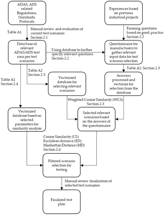
Figure 1.
Process of the developed methodology.
2.1. Review and Evaluation of Current Test Scenarios to Develop a Comprehensive Test Run Database
To create an appropriate test scenario catalog tailored to a given application, it is first necessary to gather the correct input data. For this purpose, a questionnaire was developed, which enabled a good approximation to filter for the appropriate test scenarios. Creating the questionnaire required a review of the current regulations, standards, and test protocols dealing with ADAS and autonomous vehicle testing, as well as ODD descriptions. Consequently, as an initial step in our work, we reviewed the available regulations that are in effect or soon to be enforced concerning ADAS features or autonomous vehicles, along with other decisive testing procedures, such as EuroNCAP protocols and ISO standards related to active safety (Table 1).

Table 1.
List of reviewed and processed regulations, standards, and protocols utilized for test run database development.
The goal was to gain a clearer picture of how the technology-driven working groups developing these regulations approach the problem. From the existing regulations, protocols, and standards, we gathered all the test runs per test scenarios, resulting in a list comprising more than 1000 test runs differing in parameters. We also collected the key parameters of the different runs into a database, which plays an important role in the selection of test cases. Processing the ADAS testing procedures was deemed especially important because many of them could be highly relevant to the testing of autonomous vehicles from a technological and vehicle dynamics perspective; hence, they definitely provide a good starting point in creating the planned scenario collection.
The collected parameters can be grouped into major categories based on their functionalities. Some parameters relate to the initial movement of the vehicle, such as speed, maneuver, and direction. Others pertain to the targets used (e.g., pedestrian, bicycle, car dummies), including the speed, movement, and direction of the target; overlap ratio; and target type. Additional parameters describe the specific movement of the vehicle during a test run, such as lateral speed or acceleration, or driver behavior during distraction. Environmental conditions, such as light conditions, lane markings, road edges, and traffic signs, are also considered. Not all parameters are applicable for each run, but they help compare scenarios focusing on similar functions.
Different regulations, protocols, and standards often use various terminologies to describe scenarios and define ranges, tolerances, and requirements. Therefore, we unified the terminology in the database to facilitate more effective processing in later steps (especially in the method introduced in Section 2.4). For example, in the case of the movement of the tested vehicle, i.e., Vehicle Under Test (VUT), various behaviors can be mentioned. We categorized these movements according to driving direction, such as turning left (‘Farside turn’) or right (‘Nearside turn’), driving ‘Forward’ or ‘Rearward’, or staying ‘Stationary’. Similarly, we limited the movement of targets compared to the movement of the VUT to parallel (‘Moving parallel’), perpendicular (‘Crossing’), and static (‘Stationary’) directions. In terms of the speed of the VUT and the targets, we also limited it to exact values if ranges or boundaries were given.
To ensure no useful information for testing is lost, we created relevant columns for comments where additional information can be provided if the available options do not satisfactorily describe the parameter. The parameters used for building the database, along with explanations where necessary, can be seen in Table A1 of Appendix A. Some of these parameters are selected for further analysis to help compare different runs from a similarity point of view. The method is described in Section 2.4.
2.2. Developing an Initial Questionnaire for Vehicle Developers to Aid in Selecting Test Scenarios
Prior to vehicle assessment projects, different manufacturers typically present the capabilities of their vehicle, as well as the targeted operating environment and conditions, in varying ways. Therefore, both defining the appropriate ODD and developing a test case catalogue that adequately covers it is an iterative task requiring extensive coordination and more meetings. To expedite this process, we developed a well-defined yet not overly complex and lengthy questionnaire. This questionnaire can facilitate preparation for discussions and enable the identification of relevant critical test scenarios at an early stage, especially when the vehicle needs to be tested also prior to public road testing.
To create the appropriate questionnaire, further processing of the test run catalog was necessary, while also contributing our experience from several industrial projects. It is important to formulate questions that allow for us to filter and thus narrow down the range of relevant test cases based on the given answers.
In the case of tests exclusive to autonomous vehicles, one important objective was to create suitable function groups that could be used to examine autonomous functions. This work was partially realized within the framework of an Austrian–Hungarian bilateral cooperation. The work fits in well with the previously mentioned NATM ‘multi-pillar’ approach and also relied heavily on the method developed in the course of earlier work when selecting test scenarios for measurements [25,26,27]. That project presents the definition function groups that examine whether the vehicle can respond to static or suddenly appearing objects, whether it can stay correctly in the lane, as well as its following and detection capabilities. An important input parameter when creating the questionnaire is whether the vehicle is capable of changing lanes, and if so, what the purpose is, for example, whether it is just for obstacle avoidance or planned overtaking, such as for optimization of the journey.
Among the regulations, there are also those that deal with the definition of ODDs, and, for example, the SAE J3016 standard provides a very detailed list of elements that an ODD description must cover. There are, of course, several overlaps, such as the grouping of different environments, which can well define input parameters. Based on these, we divided the possible operating environments into three groups as input parameters. The first group includes closed roads that have physical separation, at least two or more lanes in the same direction of travel, and do not contain crossing points or elements of the road network that would generally cause a stop. Typically, this includes highways and expressways. The design speed is typically higher here (generally 130 km/h in Europe, with a few exceptions).
The second group includes roads where the lanes are not physically separated from each other but that may have junctions, turning lanes, and roundabouts. These typically have a maximum of two lanes in the same direction, but more commonly one lane per direction. Rural or country roads mainly belong to this category, where the speed is more moderate but typically ranges from 50 to 100 km/h (in Europe).
The third group comprises urban areas, where there are intersections, traffic lights and signs, pedestrian crossings, roundabouts, as well as special lanes, sidewalks, and several other objects.
It is also important to examine whether the autonomous vehicle or function can handle potential transients between these environments, as well as whether it can properly exit the given environments, for example, leaving the highway or a particular road section, or turning at an intersection, i.e., whether it is capable of individually turning right or left not just for the purpose of following a predefined route, especially at intersections with high complexity [28].
Another important aspect is the handling of different traffic signs, such as adapting to changing speed limits, yielding or stopping at red lights or stop signs, and then restarting when the appropriate conditions are met.
When creating a questionnaire focused on input parameters, it is necessary to examine a few other important characteristics. These include the physical dimensions and Gross Vehicle Weight (GVW) of the vehicle and the purpose of its application (e.g., passenger or freight transport), which essentially can also define the vehicle category (M1–3; N1–3). Another important question is whether the vehicle can park autonomously and whether autonomous reversing is permitted.
It is important to highlight that the fundamental goal of the present work is the selection of critical test scenarios; therefore, it is essential to consider the vehicle as much as possible as a ‘black-box.’ We do not scrutinize the presence of various sensors, the architecture of sensor fusion, or the algorithms in detail, but instead focus on reactions in critical situations. However, independent of this, knowledge of the sensors as an input parameter is important from a functional safety standpoint to define scenarios that typically arise from sensor limitations.
Based on the above descriptions, we created a questionnaire that the manufacturer needs to fill out before we may select test scenarios for the subject vehicle. The questionnaire is presented in Appendix B. The questionnaire is designed to minimize free responses or open-ended question and to allow for respondents to select the most suitable characteristics for the vehicle from a given list. The use of closed-ended responses also helps to minimize the inclusion of subjective answers and the lack of precision in open-ended formulations, which could otherwise hinder effective filtering. Another reason for this is to reduce the need for manual processing later on; however, since during a project the focus is on a specific vehicle, it may still be worthwhile to have the responses and results reviewed by one of the experts at a TIC company. Besides some administrative information, the questionnaire contains 23 questions that focus on the given vehicle and application.
We also had the chance to try out the questionnaire with a few TIC company customers. The main purpose was to determine whether the questions were reasonable and clear. Based on the clients’ feedback, the questionnaire is clear, and they did not find it difficult to respond.
2.3. Defining Comparison Parameters: Aligning Questionnaire Responses with Database
To select the appropriate critical test cases, the vehicle manufacturer or designers must first fill out the questionnaire found in Appendix B. As mentioned in Section 2.1, a database of more than 1000 test runs was developed, with various parameters defined for each scenario. Our goal is to select the relevant scenarios from this database based on the answers from the questionnaire.
To ensure that the parameters used in test scenario database can be matched with the responses given in the questionnaire, we need to ensure compatibility. The process is illustrated in Figure 2. As previously mentioned, some questions are based on the analysis of database parameters and past experiences, allowing for certain test cases to be directly linked to relevant parameters. Out of the 23 vehicle-related questions in the questionnaire, 13 are used for selecting test cases. The remaining questions are more relevant for further vehicle assessment and functional safety analysis, which are not the focus of this work but are pertinent to the activities at a TIC company. Among the 13 questions, some are ‘yes/no’ questions, while others allow for multiple answers. The responses are processed automatically using appropriate Microsoft Excel® functions. For questions with multiple answer options, responses are stored in several columns using the one-hot encoding method. However, for some questions with multiple options, we only examine the presence of a capability without using the specific content of the answer for test case selection. Based on the responses, a unit vector consisting of 22 dimensions is created. Each of the 22 columns contains a relevant parameter, as shown in Table A2 in Appendix A.

Figure 2.
Process of evaluating questionnaire responses and test run database to generate the similarity vector.
To select the appropriate test scenarios, comparable vectors must be created from each row of the database. Initially, we manually pre-processed the database, extending it with additional parameters that follow the guidelines used when creating the questionnaire, including the following:
- Purpose (category of M or N);
- Dimension (1—≤3.5 t; 2—≤5 t; 3—≤12 t; 4—≥12 t);
- Target ODD (motorway (MW), rural road (RR), urban area (UA));
- Speed groups (1—v ≤ 30 km/h; 2—30 < v ≤ 50 km/h; 3—50 < v ≤ 100 km/h; 4—v > 100 km/h);
- Lane keeping;
- Stopping in front of static objects;
- Stopping in front of moving objects;
- Suddenly appearing objects;
- Minimum following distance;
- Detection range;
- Lane changing;
- Turning;
- Handling of traffic signs and rules;
- Handling of junctions;
- Relevance for standing passengers;
- Presence of driver;
- Parking;
- Reversing.
During pre-processing, we mainly examined whether the individual test cases were relevant to the given attribute and, in some cases, filled out the column based on values found in the original database (e.g., categorizing test runs into 1–4 categories based on speed, weight). In some cases, we also analyzed the test runs based on the applicability of a given parameter such as the typical ODD. Following this step, we used Microsoft Excel® functions to automatically create a 22-element unit vector from each row, similar to the questionnaire. The explanation for vector creation related to both the extended database and the questionnaire is provided in Table A2 of Appendix A.
Vectorizing data is a common approach when comparing large datasets. It is especially used in machine learning for tasks such as comparing different texts, images, and identifying relevant choices based on user preferences. To measure the similarity between vectors or datasets, various methods can be used. The most commonly used methods are Euclidean and Manhattan distances and cosine similarity [29,30,31].
To select the appropriate test scenarios, the vector created from the questionnaire (q) can be compared with each vector (rj) created from the database rows. We used weighted cosine similarity (WCS) for the procedure [30]. The weights (w) were defined in an array with the same number of dimensions as the vectors because the parameters stored in each vector have different importance for case selection. The weighting and explanations for the weights are also provided in Table A2. However, in the table, we proposed reasonable weights but kept the option to handle these flexible to be able to adapt better to specific vehicles. The used formula for the WCS to each test run (WCSRj) is as follows:
In Formula (1), j is the No. of the test run, and n is the dimension of the vector, which is 22 in our case.
This calculation is performed with every vector created from the database, essentially comparing the vehicle-related parameters with the parameter sets generated from each test run in the database. Based on this comparison, each test run will be assigned a value between 0 and 1. If this value is close to 1, the test run is considered relevant. It is important to establish a threshold value below which a test run is no longer considered relevant. The threshold can be selected in an adaptive manner, for example, based on the vehicle’s level of driving automation, defined in the SAE J3016TM standard. In the case of higher levels, it may be advisable to examine a larger number of test cases to ensure more robust results. However, it is also important to consider the testing environment and the type of vehicle involved. For instance, in the case of larger and heavier vehicles that could potentially cause greater harm—particularly in urban environments where Vulnerable Road Users (VRUs) may be at risk—it may be beneficial to examine more test runs, thereby lowering the threshold. Conversely, in highway environments or for passenger cars, fewer test cases may be sufficient.
During the vectorization of test cases described earlier, it may occur that two different test cases have identical vectors, resulting in the same cosine similarity value. This typically happens with test cases that are very similar to each other. To filter out overly similar test cases, we have implemented additional steps, which are detailed in the following section (Section 2.4).
2.4. Parameter Selection for Effective Filtering of Similar Test Runs
To filter out overly similar test runs, we subjected the original test run database to further processing. In this case, we also utilized vector formation. First, we selected the 10 key parameters that could cause minor or major variations in most runs. Then, using the appropriate Microsoft Excel® functions, we created a 11-dimensional vector (p) based on these parameters. In this instance, we did not only create binary vectors (0–1) but also used various values, ensuring that these values preferably fall within the range of −1 to 1. This approach prevents certain parameters (e.g., speed, which can be as high as 130 km/h) from having too much influence on the comparison, thereby distorting the results. The selected parameters are as follows:
- VUT speed [km/h];
- VUT direction;
- Target speed [km/h];
- Target movement;
- Target direction;
- Overlap;
- Obstruction;
- Lighting condition;
- Line type;
- Road type;
- Target type.
The processing methods used to assign numerical values to the parameters are detailed in Table A1 of Appendix A.
After selecting the relevant cases using WCS as described in Section 2.3, we calculated the cosine similarity (CS) from an 11-dimension vector containing only ‘1’ values (u) for test run parameters that produced identical values (CSRj) using the following formula:
In Formula (2), pj is the vector of the processed the run; j is the No. of the test run.
We sorted the calculated values from largest to smallest and then utilized two fundamental vector norms to measure distances: the ℓ1 norm, also known as the Manhattan Distance (MD), and the ℓ2 norm, known as the Euclidean Distance (ED). The MD calculates the distance between two points by summing the absolute differences of their coordinates [32]. Mathematically, in our case, for two neighboring processed test run vectors (pj and pj+1), the MD is calculated as follows using Formula (3):
The ED measures the straight-line distance between two points in Euclidean space. It is computed as the square root of the sum of the squared differences between corresponding coordinates of the vectors [32]. The ED is calculated for the same pj and pj+1 vectors with Formula (4):
Test runs with values below a certain threshold were considered too similar, and thus one or more of them were removed from the final test run collection. The threshold can be defined case by case. Based on our experiences, the threshold could be set between 0.1 and 2, depending on the purpose of the filtering, but 1 could be an ideal choice. In this case, an adaptive thresholding approach also can be used, introduced in case of WCS in the previous section (Section 2.3).
Based on our analysis during the testing of the methodology, we concluded that only scenarios that are highly similar to one another were filtered out, while those that differ more substantially remained in the dataset. Among the highly similar scenarios, it may be advisable to ensure that the most critical or hazardous one is retained. This selection could, for example, be based on the vehicle’s speed or the target object’s speed.
In the following section, we present an example calculation introducing the process of test scenario selection and also presenting the differences and advantages when using the MD or ED for selection using different thresholds.
3. Results
In the following section, we present a sample calculation based on the methodology described in Section 2.3 and Section 2.4. Additionally, we compile the appropriate scenario collection using vehicles from previous projects and analyze the extent to which the filtered scenario collection aligns with earlier test plans, which primarily relied on engineering expertise at a time when such a systematic method was not yet available.
3.1. Critical Test Scenario Selection Example Based on an Existing Vehicle
To perform the sample calculation, the first step is to select an autonomous vehicle or a vehicle equipped with an automated driving feature. The choice fell on a production vehicle with an L3 highway driving function and an automated parking feature. After completing the questionnaire, the responses shown in Table 2 were obtained. From these responses the highlighted were then used to create the vector necessary for filtering. Next, the WCS calculation was performed using Formula (1). As a result, 390 relevant test cases were identified from more than 1000 possible variations. Subsequently, using Formula (2) applying CS, the test runs were arranged in descending order based on the CS results. Following this, using Formulas (3) and (4) as described in Section 2.4, the MD and ED values were calculated. Based on these results, test runs that were too similar were excluded. During this process, we examined how the number of filtered cases evolved above 0 and 2 thresholds with a step size of 0.1.
Table 2.
Processed answers of the questionnaire and the created vectors with weights.
As shown in Figure 3, with the same threshold value, more test runs remain when using MD compared to ED. However, upon comparing the filtered cases, it is evident that the larger set provided by MD almost entirely contains the cases identified by ED in nearly all instances. Thus, we concluded that MD is preferable for creating a more comprehensive test case collection, while ED is better suited for higher-level overviews.

Figure 3.
Number of filtered test runs using calculation MD and ED.
If the threshold value is set to 1, it can be observed that 76 test runs are obtained for ED. After reviewing these cases based on professional expertise, a total of 13 cases were identified as not necessarily relevant for the given vehicle. As a result, over 80% of the test cases were deemed relevant. To further illustrate the filtering process and the rationale behind excluding highly similar test scenarios, a visual comparison of two nearly identical test runs is presented in Figure 4.
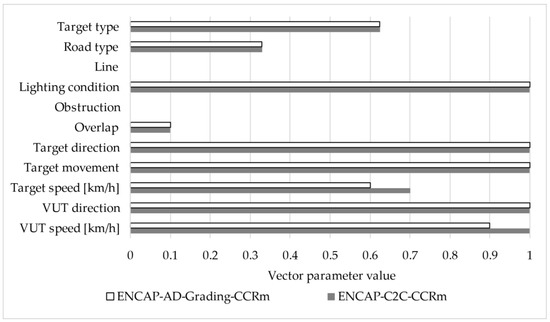
Figure 4.
Comparison of two highly similar test scenarios filtered based on ED threshold.
These scenarios differ only slightly in two parameters—VUT speed (100 km/h vs. 90 km/h) and target speed (70 km/h vs. 60 km/h)—while all other values remain identical. During the sorting process, their CS values were 0.832 and 0.829, respectively (rounded to three decimal places), and the ED between them was 0.14. Since this ED value falls below the applied threshold of 1, the test run ‘ENCAP-AD-Grading-CCR’ was excluded as redundant, while test run ‘ENCAP-C2C-CCRm’ was retained due to its slightly more critical characteristics.
A similar conclusion was reached when analyzing various threshold values. Based on these findings, we believe the developed methodology is well-suited for achieving the stated objectives.
To further examine the applicability of the methodology presented above, we conducted evaluations on two additional systems: a purely Level 3 highway diving system and a fully Automated Valet Parking System (AVPS). The results obtained from these evaluations, along with those related to the previously discussed vehicle, are summarized in Table 3 and illustrated in Figure 5. Based on the results, it can be concluded that the proposed method enables the selection of relevant scenarios effectively, while the proportion of irrelevant scenarios remained below 20% even in the worst-case scenario.
Table 3.
Number of initial, selected, filtered-out and irrelevant scenarios for three vehicles.
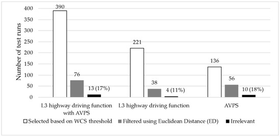
Figure 5.
Number of filtered test runs with irrelevant runs using ED for three different vehicles.
3.2. Proof of Concept: Comparing the Result of the Selection with Existing Vehicle-Specific Test Scenario Catalogues from Previous Projects
We also utilized our developed method to review previously completed projects of a TIC company to determine which scenarios should have been performed based on the filtering and compare the results with the test cases previously used. For this examination, we selected three past projects: two low-speed autonomous people mover vehicles with different capabilities and one automated highway driver function passenger car.
The scenarios used in the projects were mostly modified scenarios, although they often relied on the basic test runs found in the database. Therefore, we first identified which scenarios each one was based on or which test run group they best fit into. As a result, multiple test runs from the database could be assigned to certain previous test cases. This is significant because if we identify previous test plans’ individual runs with only one case, it is possible that during filtering, we might exclude the exact run to which the previous test case was assigned, even though this run might differ from its surroundings only in a parameter not relevant from the perspective of the previous test cases. In all three cases, we filtered using the threshold value of 1 described in Section 2.4. Based on this, we obtained the following results introduced in Table 4 supported by the illustration in Figure 6. In all three cases, the filtering allowed for us to identify several test runs that were not previously used but, upon expert review, would be relevant for testing. In all three cases, the number of not entirely relevant cases was not more than 20%. The lower match values can also be attributed to the fact that in these projects, there were instances where many very similar scenarios were applied, leading to the exclusion of related cases due to their similarity. In addition, we examined the filtered results not only in terms of quantity but also from a content-based perspective. We found that the majority of the matching scenarios were among the more well-defined and critical cases—those that had not undergone significant modifications in earlier stages and where the likelihood of collision with test objects was higher. This is likely due to the fact that, in our previous work, these well-defined test runs required fewer adjustments, making them easier to transfer from ADAS testing procedures to the evaluation of the ADS. The results can be further refined by adjusting the threshold values and WCS weighting, but this requires additional investigation.
Table 4.
Results of utilizing the developed method on test plans of pervious projects.

Figure 6.
Graphical representation of the results obtained by applying the developed methodology to test plans from previous projects.
4. Discussion
The methodology developed and presented in this study offers a systematic and efficient approach to selecting critical test scenarios for autonomous vehicles prior to their deployment in public traffic for testing or operational use. The key results demonstrate the practical applicability and relevance of a weighted cosine similarity-based filtering mechanism, combined with additional distance calculations, for scenario selection from a large database of over 1000 test cases. These results provide a foundation for improving safety validation and pre-deployment assessment of automated driving systems.
The broader implications of the developed methodology extend to multiple stakeholders across the automotive industry. For TIC companies, the methodology provides a clear framework for pre-deployment assessments, offering an efficient way to evaluate readiness and safety before public road testing. Manufacturers, on the other hand, could integrate this process into iterative design and development cycles to describing ODD and OEDR.
Moreover, the methodology demonstrates the value of leveraging existing protocols, standards, and regulations (e.g., EuroNCAP, UNECE, EU, ISO) to create standardized yet application-specific scenario catalogs. Such integration helps address regulatory gaps highlighted in recent discussions on the type approval of autonomous vehicles. For instance, by unifying terminology and parameters across diverse international testing frameworks, this study provides a foundation for comparative assessments, which is a noted challenge in the field.
From a technical perspective, the capability of the filtering process to maintain relevance in selected cases while avoiding excessive redundancy ensures that critical safety gaps are addressed without overburdening simulation or testing resources. The application of Manhattan and Euclidean distances for filtering adds further refinement, enabling flexibility in the precision of scenario selection based on testing objectives. This capability could be particularly beneficial for public authorities (supported by TICs) as they scale up ADS-related type approval frameworks.
Future developments could focus on expanding the test run database by incorporating additional standards, upcoming UNECE/EU regulations, and EuroNCAP protocols as they become available. By integrating these new standards and regulations, the methodology can be further refined to ensure an even more comprehensive and precise selection of test scenarios. Based on the continuous monitoring of the work of UN and EU working groups, as well as that of EuroNCAP and standardization bodies, we recommend updating the database on an annual basis.
The primary objective of our work was to facilitate the definition of testing procedures related to type approval practices commonly used in Europe, as currently there is no harmonized procedure among Member States regarding the pre-registration examination of such vehicles. Consequently, our methodology is grounded in regulations that are also applied within the European context—though not exclusively—since most UN regulations are valid across multiple continents. Several non-European countries, such as Japan, Turkey, and Australia, also conduct type approval based on these frameworks. Therefore, the proposed methodology may potentially be applicable in these regions as well.
Limitations
While this study presents a systematic and efficient methodology for selecting critical test scenarios for autonomous vehicles, a few limitations remain that warrant further exploration.
First, while the weighting system for the WCS calculation provides flexibility, the assignment of weights remains an area for further investigation. The default weights used in this study were based on expert judgement and case-specific adjustments; however, a more data-driven approach (e.g., machine learning optimization) could further enhance this process. Future studies could explore tuning these weights dynamically based on historical scenario relevance or real-world testing data.
Second, this study focuses on scenario filtering without delving deeply into the execution or evaluation of the filtered test scenarios. While this work emphasizes safety-critical selection, future research could aim to verify the real-world safety impact of the chosen scenarios using experimental trials or high-fidelity simulations. Additionally, the integration of reinforcement learning or other adaptive scenario generation techniques, as explored in prior studies, could further enhance the coverage of safety-critical ODDs.
Third, the scope of the scenario database may not fully capture rare edge cases or extreme environmental conditions (e.g., adverse weather, low visibility). These long-tail scenarios are critical for robust safety validation. Expanding the database to include such variables, along with performance feedback and incident data from real-world deployments, could enhance coverage and relevance.
Fourth, although the validation conducted in this study successfully matched a significant portion of the selected scenarios with relevant test applications, expanding validation efforts to a larger variety of autonomous functionalities and real-world deployment cases would provide more generalized insights into the effectiveness of the methodology.
Finally, the methodology is grounded in European and international regulatory frameworks (e.g., UNECE, EuroNCAP, ISO), which may limit its direct applicability in regions with different approval standards. In the future, it may be worthwhile to examine whether the proposed methodology could also be applied in countries where the typical type approval procedure is not in place (e.g., the United States). However, in order to establish a properly standardized test case catalogue, it is essential that the given country has existing regulations whose test cases can serve as a baseline. Nevertheless, we believe that the test plans developed from the regulations we applied could serve as a solid starting point in such countries as well, since many of the included scenarios address generally critical situations.
Author Contributions
Conceptualization, B.T. and Z.S.; methodology, B.T.; software, B.T.; validation, B.T.; formal analysis, B.T.; investigation, B.T. and Z.S.; resources, B.T.; data curation, B.T. and Z.S.; writing—original draft preparation, B.T.; writing—review and editing, B.T. and Z.S.; visualization, B.T.; supervision, Z.S.; project administration, B.T.; funding acquisition, B.T. All authors have read and agreed to the published version of the manuscript.
Funding
This research was implemented with the support provided by the Ministry of Culture and Innovation of Hungary from the National Research, Development, and Innovation Fund, financed under the KDP-2021 funding scheme.
Institutional Review Board Statement
Not applicable.
Informed Consent Statement
Not applicable.
Data Availability Statement
Restrictions apply to the availability of these data. Data were obtained from TÜV Rheinland-KTI Ltd. and are available from Balint Toth with the permission of TÜV Rheinland-KTI Ltd.
Acknowledgments
The authors are grateful to TÜV Rheinland-KTI Ltd. for providing resources, including personnel, and access to relevant testing documents and databases. During the preparation of this manuscript, the authors used TUV-GPT-4o Bot for the purpose of checking the language for grammatical mistakes and clarity. The authors have reviewed and edited the output and take full responsibility for the content of this publication.
Conflicts of Interest
The authors declare no conflicts of interest. The funders had no role in the design of the study; in the collection, analyses, or interpretation of data; in the writing of the manuscript; or in the decision to publish the results.
Abbreviations
The following abbreviations are used in this manuscript:
| ABS | Anti-lock Braking System |
| ACC | Adaptive Cruise Control |
| ACSF | Automatically Commanded Steering Function |
| ADAS | Advanced Driver Assistance Systems |
| ADDW | Advanced Driver Distraction Warning |
| ADS | Automated Driving Systems |
| AEB | Autonomous Emergency Braking/Advanced Emergency Braking |
| ALKS | Automated Lane Keeping Systems |
| AVPS | Automated Valet Parking Systems |
| BIS | British Standards Institution |
| BSIS | Blind Spot Information System (for the detection of bicycles) |
| CDCF | Corrective Directional Control Function |
| CS | Cosine Similarity |
| CSF | Corrective Steering Function |
| DCAS | Driver Control Assistance Systems |
| ED | Euclidean Distance |
| ESC | Electronic Stability Control |
| ESF | Emergency Steering Function |
| ESS | Emergency Steering Support |
| EuroNCAP | European New Car Assessment Programme |
| GVT | Global Vehicle Target |
| GVW | Gross Vehicle Weight |
| ISA | Intelligent Speed Assistance |
| LDWS | Lane Departure Warning System |
| LSS | Lane Support System |
| MD | Manhattan Distance |
| MDPI | Multidisciplinary Digital Publishing Institute |
| MOIS | Moving Off Information System |
| NATM | New Assessment/Test Method for Automated Driving |
| ODD | Operational Design Domain |
| OEDR | Object and Event Detection and Response |
| PoC | Proof of Concept |
| RECAS | Rear-End Collision Alert Signal |
| RMF | Risk Mitigation Function |
| SAE | Society of Automotive Engineers |
| SAS | Speed Assist System |
| SciL | Scenario-in-the-Loop |
| TIC | Testing, Inspection, and Certification (companies) |
| UHD | Ultra-High Definition |
| ViL | Vehicle-in-the-Loop |
| VRU | Vulnerable Road Users |
| VUT | Vehicle Under Test |
| WCS | Weighted Cosine Similarity |
Appendix A. Tables with Explanation for Data Processing
As described in Section 2.1. we gathered all the test runs per test scenarios from the existing regulations, protocols, and standards, resulting in a list comprising more than 1000 test runs. Table A1 summarizes the parameters that are applicable for two or more regulations, standards, or protocols and provides instruction on how the different test runs should be processed. The column ‘Numerical representation’ is used for building the relevant vectorized database for further selection of test runs defined in Section 2.4.
Table A1.
Parameters used to process the test runs for the database with their numerical representation for similarity analysis if applicable.
Table A1.
Parameters used to process the test runs for the database with their numerical representation for similarity analysis if applicable.
| Used Parameter 1 | Input Requirements | Comment | Numerical Representation |
|---|---|---|---|
| VUT speed [km/h] | Exact values in km/h ‘N/A’ | Only exact values or ‘N/A’ can be given. If ranges or values with < > are given, please select one of the reasonable boundaries or the middle value. The exact requirement can be provided in the related comments column. | Exact value divided by 100. In case of speed being higher than 130 km/h, value ‘1’ should be used. |
| VUT direction | ‘Forward’ ‘Rearward’ ‘Farside turn’ ‘Nearside turn’ ‘Stationary’ ‘N/A’ | Only ‘Forward’, ‘Rearward’, ‘Farside turn’ (left turn according to LHD traffic), ‘Nearside turn’ (right turn), and ‘Stationary’ can be given. If no target is used, ‘N/A’ should be entered. | ‘Forward’—‘1’ ‘Rearward’—‘−1’ ‘Farside turn’—‘0.5’ ‘Nearside turn’—‘−0.5’ ‘Stationary’—‘0’ ‘N/A’—‘0’ |
| Target speed [km/h] | Exact values in km/h ‘N/A’ ‘TBD’ | Only exact values, or N/A if no target is used, and TBD if the speed cannot be exactly determined. | Exact value divided by 100. In case of speed being higher than 130 km/h, value 1 should be used. |
| Target type | ‘EBT’ ‘EMT’ ‘EPTa’ ‘EPTc’ ‘GVT’ ‘GV-&EMT’ ‘N/A’ | ‘EBT’—bicycle target ‘EMT’—motorcycle target ‘EPTa’—adult pedestrian dummy ‘EPTc’—child pedestrian dummy ‘GVT’—global vehicle target (car) ‘GV-&EMT’—both car and motorcycle targets are needed ‘N/A’—no target | Not used for filtering |
| Target movement | ‘Crossing’ ‘Moving parallel’ ‘Stationary’ ‘N/A’ | Only ‘Crossing’ for perpendicular moving, ‘Moving parallel’ and ‘Stationary’, or ‘N/A’ can be used. The exact requirement can be provided in the related comments column. | ‘Crossing’—‘0.5’ ‘Moving parallel’—‘1’ ‘Stationary’—‘0’ ‘N/A’—‘0’ |
| Target direction | ‘Opposite direction’ ‘Same direction’ ‘Farside’ ‘Nearside’ ‘N/A’ | Only ‘Opposite direction’, ‘Same direction’, ‘Farside’, ‘Nearside’, and N/A can be used. The exact requirement can be provided in the related comments column. | ‘Opposite direction’—‘−1’ ‘Same direction’—‘1’ ‘Farside’—‘−0.5’ ‘Nearside’—‘0.5’ ‘N/A’—‘0’ |
| Overlap | Exact % values ‘N/A’ | Only exact values from —100% to 100% (usually with 25% steps) or ‘N/A’ if no target is used. | Exact value from % (i.e., 100% = 1) |
| Obstruction | ‘Yes’ ‘No’ | If the targets are used during the scenario in some specific cases, the targets are covered with other objects, like cars. In this case the scenarios are obstructed. | ‘Yes’—‘1’ ‘No’—‘0’ |
| Lateral distance [m] | Exact values ‘N/A’ | Lateral separation between the target and the VUT, mainly used in BSIS, MOIS, and door opening scenarios. | Not used for filtering |
| Longitudinal distance [m] | Exact values ‘N/A’ | Longitudinal separation between the target and the VUT, usually at the start of the functional part of a scenario. | Not used for filtering |
| Target deceleration [m/s2] | Exact values ‘N/A’ | Used in scenarios in which the target needs to brake. | Not used for filtering |
| Lighting condition | ‘Daylight’ ‘Night’ | In case of the exact illumination value [Lux] being given, it needs to be determined which option is more applicable. | ‘Daylight’—‘1’ ‘Night’—‘−1’ |
| Lateral velocity [m/s] | Exact values ‘Variable’ ‘N/A’ | Exact values, or ‘Variable’ if it can be changed, and ‘N/A’ if not related to lane departure. | >0.5—‘1’ >0 or ‘Variable’—‘0.5’ N/A—‘0’ |
| Lateral acceleration [m/s2] | Exact values ‘N/A’ | Usually, lateral acceleration during lane keeping in curves. | Not used for filtering |
| Side | ‘Driver’ ‘Passenger’ | Direction of the lane departure. | Not used for filtering |
| Line type | ‘Dashed’ ‘Solid’ ‘Road edge’ ‘N/A’ | Types of relevant lane markings should be mentioned. In case of no lane markings, ‘N/A’ or ‘Road edge’ should be used. | ‘Dashed’—‘0–5’ ‘Solid’—‘1’ ‘Road edge’—‘−1’ ‘N/A’—‘0’ |
| Intention | ‘Intentional’ ‘Unintentional’ | If applicable, the type of lane approach should be defined. | Not used for filtering |
| Road type | ‘Curved’ ‘Straight’ ‘Intersection’ ‘Non-urban’ ‘Urban’ ‘Motorway’ ‘N/A’ | According to the reviewed documentation, these types were mentioned. For the filtering, these could be categorized in three main groups. | ‘Curved’—‘0.66’ ‘Straight’—‘0.33’ ‘Intersection’—‘1’ ‘Non-urban’—‘0.66’ ‘Urban’—‘1’ ‘Motorway’—‘0.33’ ‘N/A’—‘0’ |
| Traffic Sign | Exact value ‘Explicit’ ‘Implicit’ ‘N/A’ | Naming according to Regulation (EU) 2021/1958 (ISA). Use exact value in case of the speed limit being given on an explicit sign. Use ‘Explicit’ if the number is not defined. | Not used for filtering |
| Weight condition | ‘Loaded’ ‘Unloaded’ | Use ‘Unloaded’ if the test shall be carried out with ‘mass in running order’ or not specified. If weights should be used, then use ‘Loaded1’. | Not used for filtering |
| Category | ‘M1’, ‘M2’, ‘M3’ ‘N1’, ‘N2’, ‘N3’ | Category is based on the purpose of the vehicle such as carrying of passengers (M) or goods (N), and the weight (1–3). | Not used for filtering |
1 Only parameters that are applicable for two or more regulations, standards, or protocols are listed here.
As described in Section 2.3, to ensure compatibility between the parameters used in the test scenario database and the responses given in the questionnaire, we identified parameters that can be used for both analyzing the relevant answers from the questionnaire and parameters from the test run database. Table A2 shows the defined ‘Vector parameter’ with the explanation of each parameter and also the rationale for the database of the test runs and for the questionnaire. For the latter, the relevant questions are also referenced, with their numbering corresponding to the numbering in Appendix B. The weights used in Formula (1) and their explanation are also introduced in Table A2.
Table A2.
Explanation of vector formulation from the responses of the questionnaire and from the test run database with their weights.
Table A2.
Explanation of vector formulation from the responses of the questionnaire and from the test run database with their weights.
| Vector Parameter | Explanation | Rationale of the Database | Rationale of the Questionnaire | Explanation of Weight | Weight |
|---|---|---|---|---|---|
| M | Vehicle category for carrying passengers | Processed with ‘one-hot encoding’. The scope vehicle category is specified in the regulations, standards, and protocols and included in the ‘Category’ column in the database. | Processed with ‘one-hot encoding’. Question 1 parameters: Transportation of passengers: M; Carrying goods: N. | Weight is shared equally between vector parameter ‘M’ and ‘N’ because these belong to one question or database parameter. | 0.5 |
| N | Vehicle category for carrying goods | 0.5 | |||
| Dimensions 1—≤3.5 t | Vehicles with GVW under 3.5 t | Processed with ‘one-hot encoding’. The scope vehicle dimension is specified in the regulations, standards, and protocols and included in the ‘Dimensions’ column in the database. | Processed with ‘one-hot encoding’. Processing is based on the answer to Question 5. The function checks the GVW of the vehicle and fills the right column with ‘1’. | Weight is shared equally between the 4 different ‘Dimension’ vector parameters because these belong to one question or database parameter. | 0.25 |
| Dimensions 2—≤5 t | Vehicles with GVW between 3.5 t and 5 t | 0.25 | |||
| Dimensions 3—≤12 t | Vehicles with GVW between 5 t and 12 t | 0.25 | |||
| Dimensions 4—≥12 t | Vehicles with GVW above 12 t | 0.25 | |||
| MW | Closed roads with physical separation and at least two or more lanes in the same direction of travel, without junctions (e.g., motorways, expressways) | Processed with ‘one-hot encoding’ based on the manually extended test run database checking the ‘Target ODD’ column. | Processed with ‘one-hot encoding’ based on the answer to Question 6 of the questionnaire. | Weight is shared equally between the 3 different types of environments (MW, RR, UA) in the vector parameter because these belong to one question or database parameter. | 0.33 |
| RR | Non-separated roads, with one or two lanes in one direction, with possible junctions, roundabouts (e.g., rural or country roads) | 0.33 | |||
| UA | Urban environments with various junctions, traffic management system, buildings, etc. (e.g., cities, villages) | 0.33 | |||
| Speed v ≤ 30 km/h | VUT speed under 30 km/h during test execution | Processed with ‘one-hot encoding’. The speed or speed range of the test run is specified in the regulations, standards, and protocols and included in the ‘Speed’ column in the database. | Processed with ‘one-hot encoding’. Processing is based on the answer to Question 8. The function checks the planned maximum operational speed of the vehicle and fills the right column with ‘1’. | Weight is shared equally between the 4 different ‘Dimension’ vector parameters because these belong to one question or parameter. However, if a well-defined speed range is provided in the questionnaire for the planned maximum and minimum operational speeds, the affected range can be given a larger weight (e.g., 0.5). | 0.25 |
| Speed 30 < v ≤ 50 km/h | VUT speed between 30 and 50 km/h during test execution | 0.25 | |||
| Speed 50 < v ≤ 100 km/h | VUT speed between 50 and 100 km/h during test execution | 0.25 | |||
| Speed v > 100 km/h | VUT speed above 100 km/h during test execution | 0.25 | |||
| Lane keeping | Analyzing whether the test runs are relevant for lane keeping situations, and whether the vehicle is capable of keeping its current driving lane | In the manually extended test run database, scenarios that are relevant for lane keeping are marked with an ‘x’. The function searches for these runs and fills the column with ‘1’ if it finds any. | Question 10 targets the lane keeping capabilities of the vehicle. The column is filled with ‘1’ if the answer is ‘Yes’. | Lane keeping is a crucial capability in an automated driving function; therefore, it is assigned a larger weight. | 1 |
| Safe distance | Analyzing whether the test runs are relevant for vehicle following and AEB situations, and whether the vehicle is capable of performing in them | In the manually extended test run database, runs are marked with an ‘x’ if the run is relevant. for ‘Stopping in front of a static object’, ‘Stopping in front of a moving object’, or ‘Suddenly appearing objects’. The function searches for these runs and fills the column with ‘1’ if it finds any. | Question 11 targets the safe distance maintenance capabilities of the vehicle. The column is filled with ‘1’ if the answer is ‘Yes’. | Keeping a safe distance from other road users is a crucial capability of an automated driving function; therefore, it is assigned a larger weight. | 1 |
| Lane changing | Analyzing whether the test runs are relevant for lane changing situations, and whether the vehicle is capable of changing its current driving lane | In the manually extended test run database, scenarios that are relevant for lane changing are marked with an ‘x’. The function searches for these runs and fills the column with ‘1’ if it finds any. | Question 12 targets the lane changing capabilities of the vehicle. The column is filled with ‘1’ if any answer is selected. | Lane changing is an important automated driving function, so the default weight is large. However, based on the selected answers in the questionnaire, the weight can be adjusted to a lower value. | 0.33–1 |
| Turning | Analyzing whether the test runs are relevant for turning, and whether the vehicle is capable of turning aside from when it is following its driving lane | In the manually extended test run database, scenarios that are relevant for turning are marked with an ‘x’. The function searches for these runs and fills the column with ‘1’ if it finds any. | Question 13 targets the turning capabilities of the vehicle. The column is filled with ‘1’ if the answer is ‘Yes’. | Turning is a crucial capability in an automated driving function; therefore, it is assigned a larger weight. | 1 |
| Handling of traffic signs and rules | Analyzing whether the test runs are relevant for handling of traffic signs and rules, and whether the vehicle is capable of handling of traffic signs and rules | In the manually extended test run database, scenarios that are relevant for handling of traffic signs and rules are marked with an ‘x’. The function searches for these runs and fills the column with ‘1’ if it finds any. | Question 14 is checking whether the vehicle is capable of handling of traffic signs and rules. The column is filled with ‘1’ if any answer is selected. | Handling of traffic signs and rules could be an important driving function, so the default weight is large. However, based on the selected answers in the questionnaire, the weight can be adjusted to a lower value. | 0.2–1 |
| Handling of junctions | Analyzing whether the test runs are relevant for handling of junctions, and whether the vehicle is capable of handling of junctions | In the manually extended test run database, scenarios that are relevant for handling of junctions are marked with an ‘x’. The function searches for these runs and fills the column with ‘1’ if it finds any. | Question 12 targets junction handling capabilities of the vehicle. The column is filled with ‘1’ if any answer is selected. | Handling of junctions could be an important driving function, so the default weight is large. However, based on the selected answers in the questionnaire, the weight can be adjusted to a lower value. | 0.25–1 |
| Relevance for standing passengers | Analyzing whether the test runs are relevant for standing passengers, and whether the vehicle is capable of recognizing and handling if there are standing passengers on board | In the manually extended test run database, scenarios that are relevant for standing passengers are marked with an ’x’. The function searches for these runs and fills the column with ‘1’ if it finds any. | Question 16 checks whether the vehicle is capable of recognizing and handling if there are standing passengers on board. The column is filled with ‘1’ if the answer is ‘Yes’. | In the case of standing passengers, the vehicle needs to adapt its dynamics accordingly, making this an important parameter. | 1 |
| Reversing | Analyzing whether the test runs are relevant for reversing, and whether the vehicle is capable of reversing | In the manually extended test run database, scenarios that are relevant for reversing are marked with an ’x’. The function searches for these runs and fills the column with ‘1’ if it finds any. | Question 18 targets the reversing capabilities of the vehicle. The column is filled with ‘1’ if the answer is ‘Yes’. | Reversing could be a more critical maneuver, so the weight of this parameter is also larger. | 1 |
| Parking | Analyzing whether the test runs are relevant for parking, and whether the vehicle is capable of parking | In the manually extended test run database, scenarios that are relevant for parking are marked with an ‘x’. The function searches for these runs and fills the column with ‘1’ if it finds any | Question 19 targets reversing capabilities of the vehicle. The column is filled with ‘1’ if any answer is selected. | Automated parking could be an important capability in the future, so the basic weight is larger. However, based on the selected answers in the questionnaire, the weight can be adjusted to a lower value. | 0.33–1 |
Appendix B. Questionnaire
The questionnaire is available at the following link, but the actual copy of the relevant part also can be read in this section: https://forms.gle/Fd7b7GpUw8m51kfb6.
The questionnaire starts with a section containing administrative questions; then, in the second section, the following questions target the vehicle and its capabilities. The types of questions used in this questionnaire are as follows:
- ‘Multiple choice’: one answer shall be selected from the list;
- ‘Checkboxes’: more options can be selected from the list;
- ‘Short answer’: a short text should be the answer;
- ‘Paragraph’: a longer text can be used as an answer.
In case a question is required to be answered it is marked with ‘*’. The questions are as follows:
- Purpose of the application * (Multiple choice)
- Transporting of passengers
- Carrying goods
- Other: …
- Length of the vehicle in mm * (Short answer)
- Height of the vehicle in mm * (Short answer)
- Width of the vehicle in mm * (Short answer)
- Weight of the vehicle in kg (GVW) * (Short answer)
- Target operational environment * (Checkboxes)
- MW: Closed roads with physical separation and at least two or more lanes in the same direction of travel, without junctions (e.g., motorways, expressways)
- RR: Non-separated roads, with one or two lanes in one direction, with possible junctions, roundabouts (e.g., rural or country roads)
- UA: Urban environments with various junctions, traffic management system, buildings, etc. (e.g., cities, villages)
- Private closed environment without public traffic
- Does the vehicle handle transient between the ODDs? If not, leave it empty. (Checkboxes)
- Handles between MW-RR types (e.g., leaving or entering a motorway)
- Handles between MW-UA types (e.g., a motorway directly flows into a suburban area of a larger city)
- Handles between RR-UA types (e.g., regular city limits with new speed limits)
- Planned maximum operational speed in km/h? * (Short answer)
- Planned minimum operational speed in km/h? * (Short answer)
- Is the vehicle capable of keeping in the lane? * (Multiple choice)
- Yes
- No
- Is the vehicle capable of maintaining safe distance? * (Multiple choice)
- Yes
- No
- Is the vehicle capable of changing between lanes? If not, leave it empty. (Checkboxes)
- Yes, to avoid critical situations and obstacles
- Yes, for overtaking
- Turning (not equivalent with turning for lane keeping). I.e., turning to leave the current road in junctions. * (Multiple choice)
- Yes
- No
- Handling of traffic rules and signs (please select from the list below; if none of the options are applicable, please leave it empty). (Checkboxes)
- Speed limits (e.g., speed-limit signs or map data)
- Traffic signs (especially ‘give-way’ and ‘STOP’)
- Traffic lights
- Lane markings
- Special lanes (e.g., BUS, bicycle)
- Handling of junctions (please select from the list below; if none of the options are applicable, please leave it empty). (Checkboxes)
- Stop and go further in the original road in junctions
- Turning right from the main road in junctions
- Turning left from the main road in junctions
- U-turn in relevant junctions
- Transportation of standing passengers? * (Multiple choice)
- Yes
- No
- Type of supervision * (Checkboxes)
- Remote
- Safety operator with longitudinal ‘2-bit’ control
- Safety operator with longitudinal and lateral control
- Other: …
- Capable of reversing in automated mode? * (Multiple choice)
- Yes
- No
- Automated parking (please select from the list below; if none of the options are applicable, please leave it empty). (Checkboxes)
- Parking forward in perpendicular or angled
- Parking backwards in perpendicular or angled
- Parallel parking
- Type of sensors for automated functions * (Checkboxes)
- dGNSS
- LiDAR
- Radar
- Camera
- Ultrasonic
- Other: …
- Is the deployment of the vehicle planned in left-hand traffic (LHT) or right-hand traffic (RHT)? * (Checkboxes)
- LHT
- RHT
- Targeted level of driving automation according to SAE J3016 (Multiple choice)
- LEVEL 3
- LEVEL 4
- LEVEL 5
- Please provide any additional information about the vehicle that you think is important for scenario catalogue development. (Paragraph)
References
- Myers, R.; Saigol, Z. Pass-Fail Criteria for Scenario-Based Testing of Automated Driving Systems. arXiv 2020, arXiv:2005.09417v2. [Google Scholar]
- UNECE: New Assessment/Test Method for Automated Driving (NATM) Guidelines for Validating Automated Driving System (ADS). 2022. Available online: https://unece.org/sites/default/files/2022-04/ECE-TRANS-WP.29-2022-58.pdf (accessed on 25 March 2025).
- Commission Implementing Regulation (EU) 2022/1426 of 5 August 2022 Laying down Rules for the Application of Regulation (EU) 2019/2144 of the European Parliament and of the Council as Regards Uniform Procedures and Technical Specifications for the Type-Approval of the Automated Driving System (ADS) of Fully Automated Vehicles (Text with EEA Relevance). Available online: https://eur-lex.europa.eu/legal-content/EN/TXT/?uri=CELEX%3A32022R1426 (accessed on 25 March 2025).
- Yan, M.; Rampino, L.; Caruso, G. Comparing User Acceptance in Human–Machine Interfaces Assessments of Shared Autonomous Vehicles: A Standardized Test Procedure. Appl. Sci. 2025, 15, 45. [Google Scholar] [CrossRef]
- PEGASUS Projekt: Scenario Description. 2019. Available online: https://www.pegasusprojekt.de/files/tmpl/PDF-Symposium/04_Scenario-Description.pdf (accessed on 25 March 2025).
- UNECE 1958 Agreement: Addendum 170–UN Regulation No. 171: Uniform Provisions Concerning the Approval of Vehicles with Regard to Driver Control Assistance Systems. 2024. Available online: https://unece.org/sites/default/files/2025-01/R171e%20%282%29.pdf (accessed on 14 February 2025).
- Vass, S.; Donà, R.; Mattas, K.; Morandin, G.; Toth, B.; Heé, M.Á.; Galassi, M.C.; Ciuffo, B. Are Low-Speed Automated Vehicles Ready for Deployment? Implications on Safety and Urban Traffic. Transp. Res. Part C 2023. submitted.. [Google Scholar]
- KBA: Autonome-Fahrzeuge-Genehmigungs-Und Betriebs-Verordnung (AFGBV). 2022. Available online: https://www.gesetze-im-internet.de/afgbv/ (accessed on 13 March 2025).
- Kalra, N.; Paddock, S.M. Driving to Safety: How Many Miles of Driving Would It Take to Demonstrate Autonomous Vehicle Reliability? Transp. Res. Part. A Policy Pract. 2016, 94, 182–193. [Google Scholar] [CrossRef]
- Donà, R.; Ciuffo, B. Virtual Testing of Automated Driving Systems. A Survey on Validation Methods. IEEE Access 2022, 10, 24349–24367. [Google Scholar] [CrossRef]
- Razdan, R.; Akbaş, M.İ.; Sell, R.; Bellone, M.; Menase, M.; Malayjerdi, M. PolyVerif: An Open-Source Environment for Autonomous Vehicle Validation and Verification Research Acceleration. IEEE Access 2023, 11, 28343–28354. [Google Scholar] [CrossRef]
- Katzorke, N.; Vinçon, C.; Kolar, P.; Lasi, H. Fields of Interest and Demands for a Digital Proving Ground Twin. Transp. Res. Interdiscip. Perspect. 2023, 18, 100782. [Google Scholar] [CrossRef]
- Toth, B.; Szalay, Z. Development and Functional Validation Method of the Scenario-in-the-Loop Simulation Control Model Using Co-Simulation Techniques. Machines 2023, 11, 1028. [Google Scholar] [CrossRef]
- Szalay, Z.; Szalai, M.; Tóth, B.; Tettamanti, T.; Tihanyi, V. Proof of Concept for Scenario-in-the-Loop (SciL) Testing for Autonomous Vehicle Technology. In Proceedings of the 2019 IEEE International Conference on Connected Vehicles and Expo (ICCVE), Graz, Austria, 4–8 November 2019. [Google Scholar]
- MATLAB Help Center: Simulate Vehicle Dynamics in ZalaZONE Automotive Proving Ground 3D Scene. Available online: https://ch.mathworks.com/help/vdynblks/ug/simulate-vehicle-dynamics-in-zalazone-automotive-proving-ground-3d-scene.html (accessed on 11 April 2025).
- Katzorke, N.; Moosmann, M.; Imdahl, R.; Lasi, H. A Method to Assess and Compare Proving Grounds in the Context of Automated Driving Systems. In Proceedings of the 2020 IEEE 23rd International Conference on Intelligent Transportation Systems (ITSC), Rhodes, Greece, 20–23 September 2020. [Google Scholar]
- Shakeri, A. Formalization of Operational Domain and Operational Design Domain for Automated Vehicles. In Proceedings of the 2024 IEEE 24th International Conference on Software Quality, Reliability, and Security Companion (QRS-C), Cambridge, UK, 1–5 July 2024. [Google Scholar]
- Eichenseer, F.; Sarkar, S.; Shakeri, A. A Systematic Methodology for Specifying the Operational Design Domain of Automated Vehicles. In Proceedings of the 2024 IEEE 35th International Symposium on Software Reliability Engineering Workshops (ISSREW), Tsukuba, Japan, 28–31 October 2024. [Google Scholar]
- Feng, S.; Feng, Y.; Yan, X.; Shen, S.; Xu, S.; Liu, H.X. Safety Assessment of Highly Automated Driving Systems in Test Tracks: A New Framework. Accid. Anal. Prev. 2020, 144, 105664. [Google Scholar] [CrossRef] [PubMed]
- Feng, S.; Feng, Y.; Sun, H.; Zhang, Y.; Liu, H.X. Testing Scenario Library Generation for Connected and Automated Vehicles: An Adaptive Framework. IEEE Trans. Intell. Transport. Syst. 2022, 23, 1213–1222. [Google Scholar] [CrossRef]
- Li, S.; Li, W.; Li, P.; Ma, P.; Yang, M. Novel Test Scenario Generation Technology for Performance Evaluation of Automated Vehicle. Int. J. Automot. Technol. 2022, 23, 1295–1312. [Google Scholar] [CrossRef]
- Wang, Z.; Ma, J.; Lai, E.M.-K. A Survey of Scenario Generation for Automated Vehicle Testing and Validation. Future Internet 2024, 16, 480. [Google Scholar] [CrossRef]
- Wu, X.; Chen, J.; Xing, X.; Sun, J.; Tian, Y.; Liu, L.; Shen, Y. LAMBDA: Covering the Multimodal Critical Scenarios for Automated Driving Systems by Search Space Quantization. arXiv 2024, arXiv:2412.00517. [Google Scholar]
- Dong, H.; Hu, Q.; Li, D.; Li, Z.; Song, Z. Predictive Battery Thermal and Energy Management for Connected and Automated Electric Vehicles. IEEE Trans. Intell. Transp. Syst. 2025, 26, 2144–2156. [Google Scholar] [CrossRef]
- Reckenzaun, J.; Csanady, L.; Eichberger, A.; Engelstein, A.; Hörmann, L.; Kiss, T.; Luley, P.; Rüther, M.; Schwarz, S.; Strasser-Krauss, T.; et al. Transnational Testing, Operation and Certification of Automated Driving Systems: Perspective from testEPS and Central System EUREKA Projects. In Proceedings of the 2022 International Conference on Connected Vehicle and Expo (ICCVE), Lakeland, FL, USA, 7–9 March 2022. [Google Scholar]
- Reckenzaun, J.; Rott, R.; Kirchengast, M.; Ritter, D.J.; Innerwinkler, P.; Solmaz, S.; Pilz, C.; Schratter, M.; Eichberger, A.; Mihalj, T.; et al. Transnational Testing, Operation and Certification of Automated Driving Systems: Perspective from testEPS and Central System EUREKA Projects-Mid-Term Results. In Proceedings of the 2023 IEEE International Automated Vehicle Validation Conference (IAVVC), Austin, TX, USA, 16–18 October 2023. [Google Scholar]
- Reckenzaun, J.; Rott, R.; Nikolić, O.; Innerwinkler, P.; Kirchengast, M.; Ritter, D.J.; Solmaz, S.; Ladstätter, S.; Luley, P.; Toth, B.; et al. Transnational Testing, Operation and Certification of Automated Driving Systems–Building Bricks for the NATM Multi-Pillar Framework. In Proceedings of the 2024 IEEE International Automated Vehicle Validation Conference (IAVVC), Pittsburgh, PA, USA, 22–23 October 2024. [Google Scholar]
- Li, J.; Zong, R.; Wang, Y.; Deng, W. Complexity Evaluation for Urban Intersection Scenarios in Autonomous Driving Tests: Method and Validation. Appl. Sci. 2024, 14, 10451. [Google Scholar] [CrossRef]
- Xia, P.; Zhang, L.; Li, F. Learning Similarity with Cosine Similarity Ensemble. Inf. Sci. 2015, 307, 39–52. [Google Scholar] [CrossRef]
- Steck, H.; Ekanadham, C.; Kallus, N. Is Cosine-Similarity of Embeddings Really About Similarity? In Proceedings of the Companion ACM Web Conference 2024, Singapore, 13–17 May 2024. [Google Scholar]
- Wang, D.; Lu, H.; Bo, C. Visual Tracking via Weighted Local Cosine Similarity. IEEE Trans. Cybern. 2015, 45, 1838–1850. [Google Scholar] [CrossRef] [PubMed]
- Boyd, S.; Vandenberghe, L. Chapter 3: Norm and distance. In Introduction to Applied Linear Algebra: Vectors, Matrices, and Least Squares, 1st ed.; Cambridge University Press: Cambridge, UK, 2018; pp. 45–68. [Google Scholar]
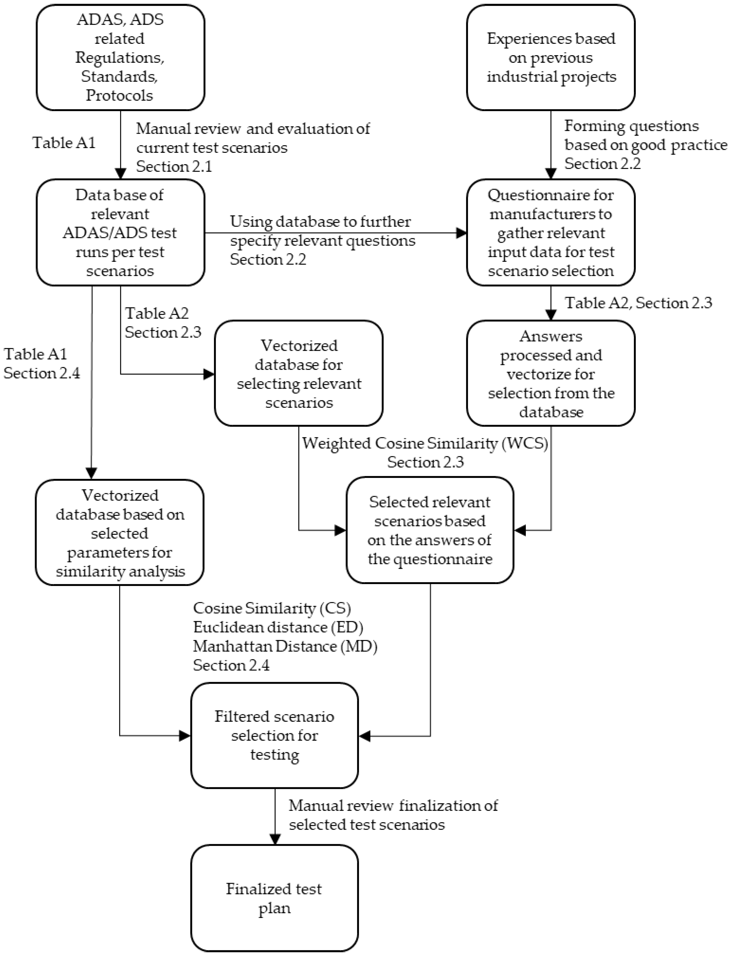
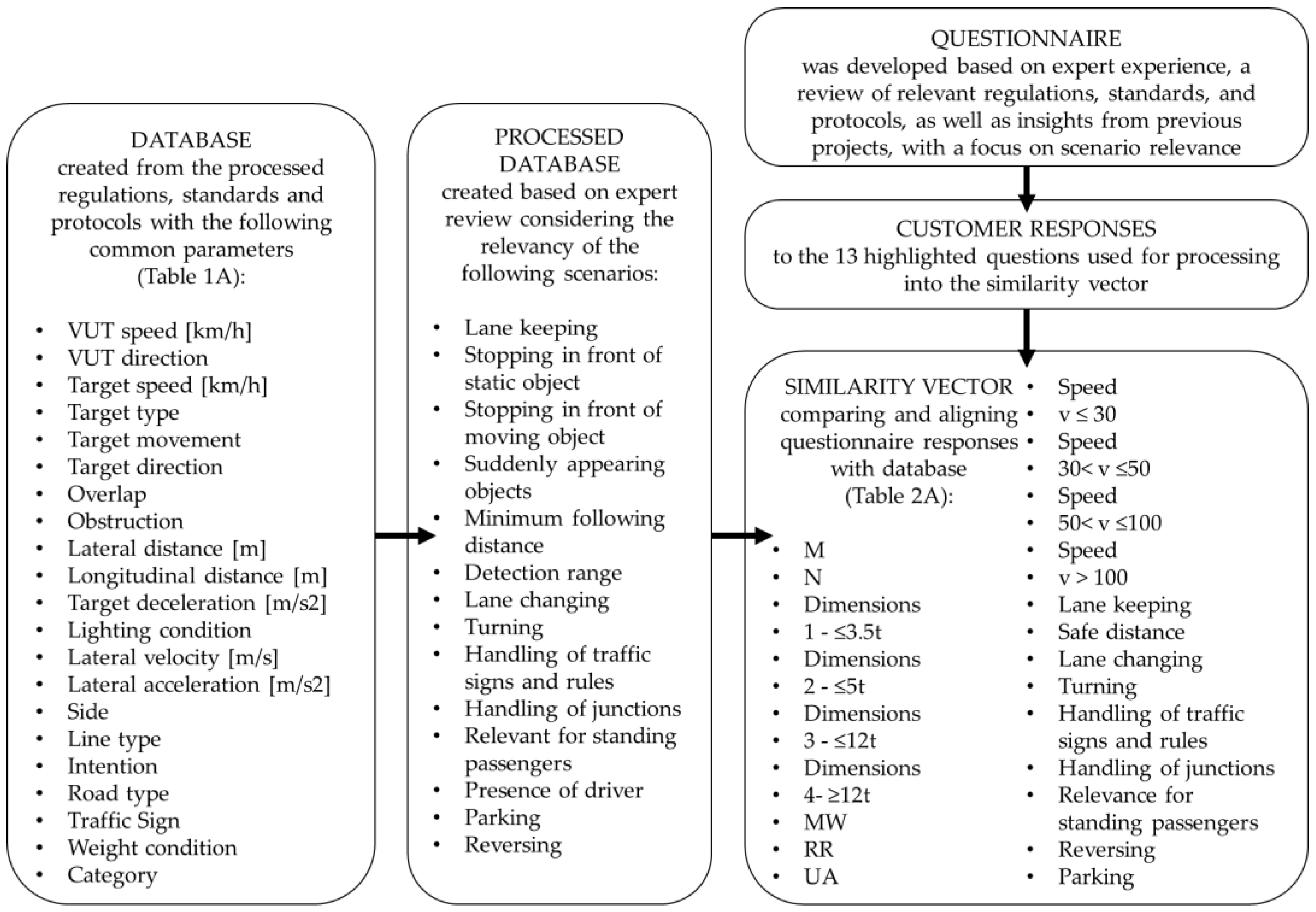
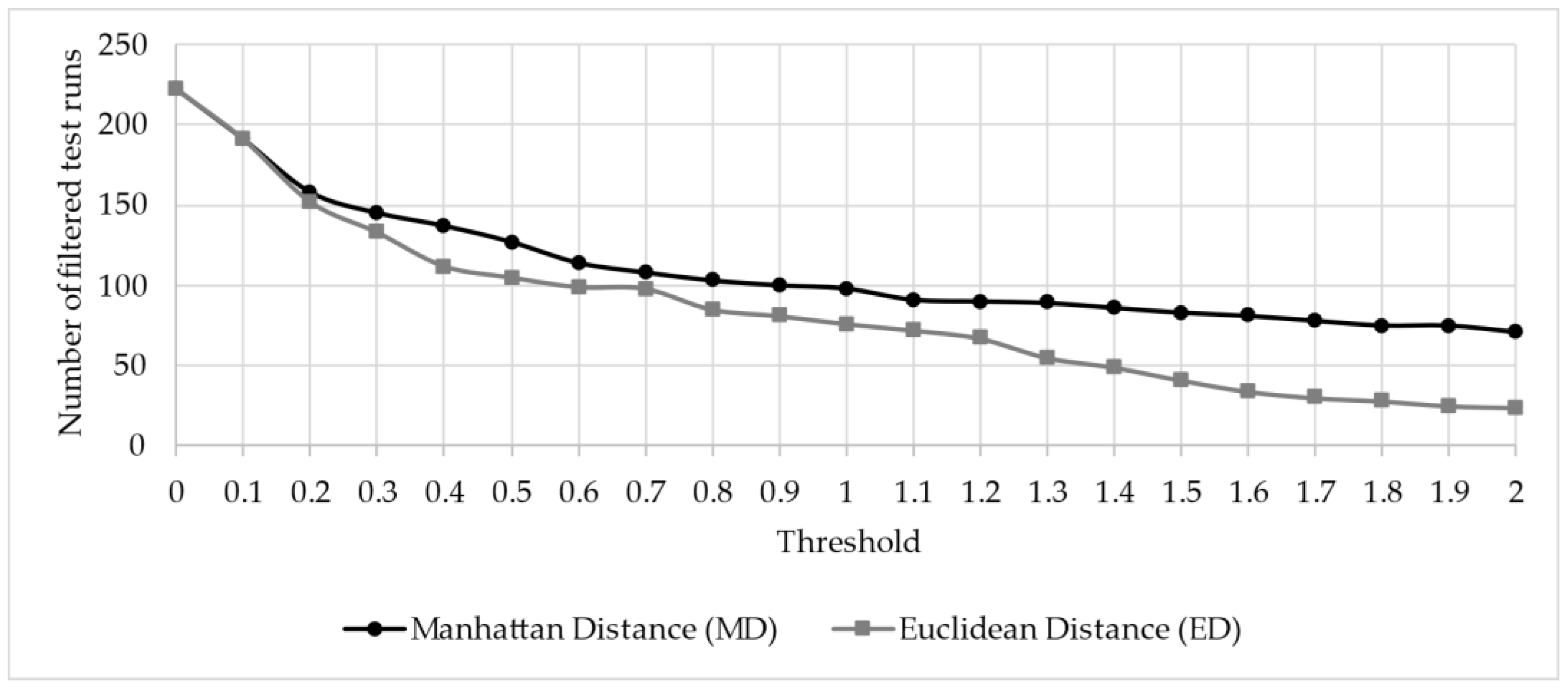
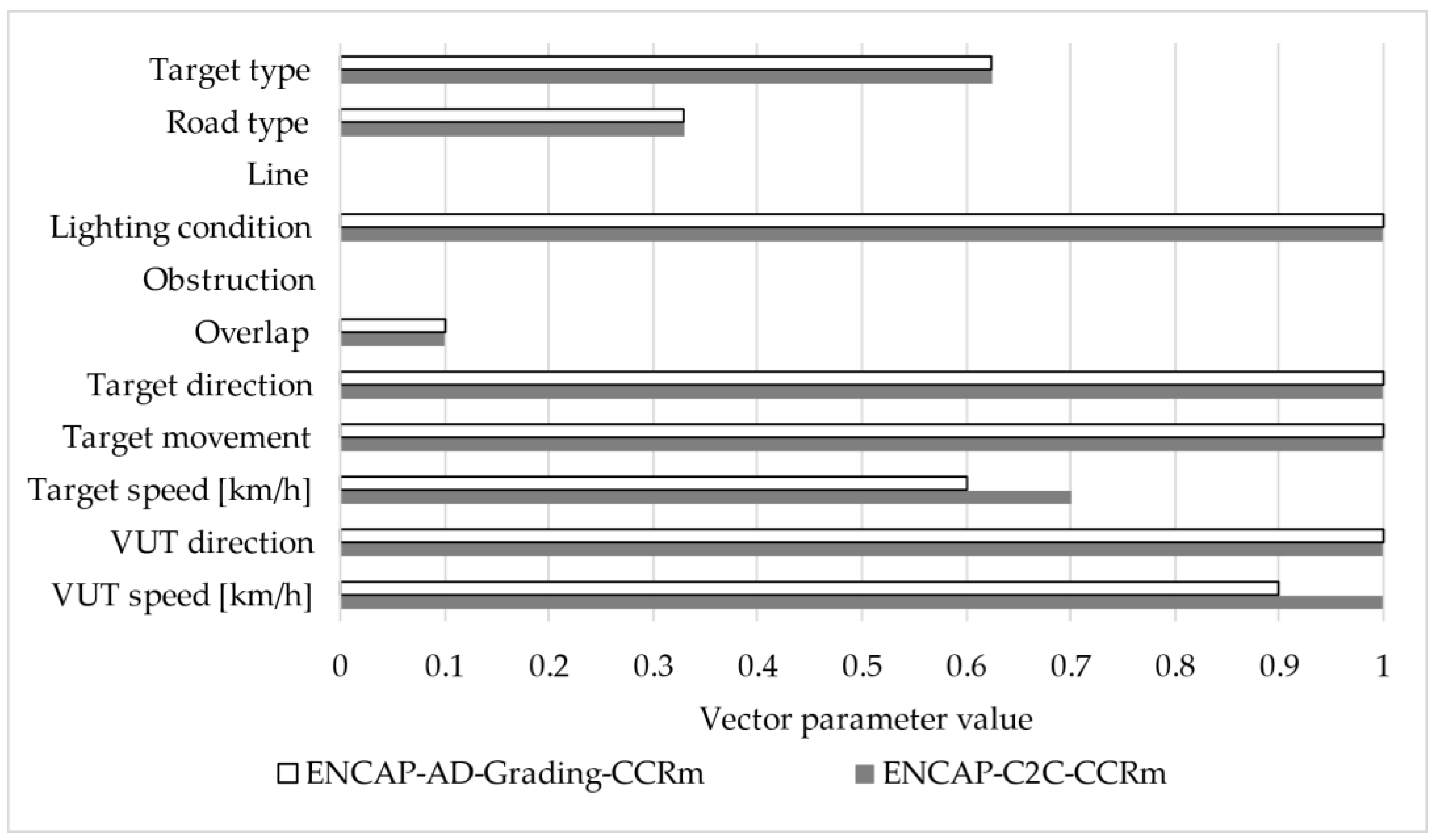

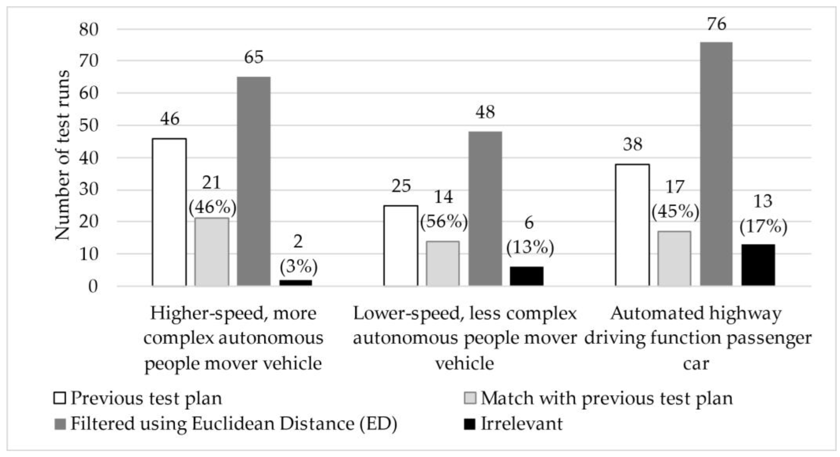
Disclaimer/Publisher’s Note: The statements, opinions and data contained in all publications are solely those of the individual author(s) and contributor(s) and not of MDPI and/or the editor(s). MDPI and/or the editor(s) disclaim responsibility for any injury to people or property resulting from any ideas, methods, instructions or products referred to in the content. |
© 2025 by the authors. Licensee MDPI, Basel, Switzerland. This article is an open access article distributed under the terms and conditions of the Creative Commons Attribution (CC BY) license (https://creativecommons.org/licenses/by/4.0/).