Article

Comparative Corrosion and Wear Behaviors of Cermet Coatings Obtained from Conventional and Recycled Powders

1
Materials and Manufacturing Engineering Department, Faculty of Mechanical Engineering, Politehnica University of Timisoara, Bvd. Mihai Viteazu nr. 1, 300222 Timisoara, Romania
2
Institute of Mechanical Engineering, Westphalian University of Applied Sciences, Neidenburgerstr. 43, 45897 Gelsenkirchen, Germany
*
Authors to whom correspondence should be addressed.
Appl. Sci. 2025, 15(14), 7654; https://doi.org/10.3390/app15147654
Submission received: 19 June 2025 / Revised: 5 July 2025 / Accepted: 7 July 2025 / Published: 8 July 2025

Abstract

Many components in industry are subjected to high loads during operation and therefore often do not reach their intended service life. Conventional steels frequently do not provide sufficient protection against wear and corrosion. One solution is to coat these components using methods like thermal spraying to apply cermet coatings such as Cr3C2-NiCr or WC-Co-Cr. In light of increasingly strict environmental regulations, more eco-friendly alternatives are needed, especially ones that use little or no Cr, Ni, Co, or W. Another alternative is the recycling of powder materials, which is the focus of this research project. This study investigated whether filter dust from an HVOF system could be used to develop a new coating suitable for use in applications requiring resistance to wear and corrosion. This is challenging as the filter dusts have heterogeneous compositions and irregular particle sizes. Nevertheless, this recycled material, referred to as “Green Cermets” (GCs), offers previously untapped potential that may also be of ecological interest. An established WC-Co-Cr coating served as a reference. In addition to friction wear and corrosion resistance, the study also examined particle size distribution, hardness, microstructure, and susceptibility to crack formation at the interface and inside the coating. Even though the results revealed a diminished performance of the GC coatings relative to the conventional WC-CoCr, they may still be applicable in various industrial applications.

1. Introduction

Thermal spraying is a deposition technique within the field of surface engineering. Various sub-processes can be used to apply coatings with thicknesses ranging from 10 µm to several millimeters. The substrate undergoes minimal thermal stress, so no structural transformations are expected in materials such as steel. A well-known process is High Velocity Oxy-Fuel (HVOF) spraying, which is also used in repair applications [1,2,3].
This method enables the production of corrosion- and wear-resistant coatings with particularly low porosity, often below 1.0% [1,2,4,5]. Thermal spraying, especially HVOF, is often the focus of research involving simulations to investigate multiphase flow problems. The aim is to improve the cost-effectiveness and efficiency of the process [4,6].
Several studies have shown that the relatively low flame temperature in the HVOF process, compared to other coating processes, combined with the high kinetic energy, results in improved coating properties. One such improvement is reduced oxide formation during deposition, positively affecting the surface composition of the coating [5,7,8].
Cermet coatings such as WC-Co or Cr3C2-NiCr are often used as an alternative to hard chrome coatings [9,10,11]. Both cermet coatings offer properties comparable to those of hard chrome coatings, or even significantly better properties, such as corrosion resistance. WC-based coatings exhibit high wear resistance, primarily due to their high hardness, which typically exceeds 1000 HV. When combined with Co or Co-Cr they also demonstrate excellent toughness and ductility while maintaining high strength due to the combination of a hard phase and a metallic binder matrix [1,3,4,12,13].
A typical feature of WC-based coatings is their high density. For thermally sprayed WC-Co materials this lies around 15–16 g/cm3. These coatings are generally suitable for use at temperatures up to around 450 °C. Beyond this, tungsten carbides demonstrate inadequate thermal stability [9,14,15,16,17,18]. Excessive thermal stress during deposition, for example, can lead to decarburization (the formation of W2C) or oxidation, increasing the heterogeneity of the coating [4]. Operation at higher temperatures (>450 °C) further increases the risk of surface oxidation [4,19].
The suitable particle sizes for HVOF spraying vary significantly depending on the application. In general, this technique cannot be used to process nanoparticles [2].
WC-Co-Cr coatings also demonstrate excellent corrosion resistance. Studies are often conducted in environments resembling seawater (3.5% NaCl, presence of Cl), where the chromium content significantly improves corrosion resistance compared to WC-Co [14,20,21,22]. Thanks to their high hardness and outstanding wear and corrosion resistance, WC coatings are widely used in demanding fields such as aerospace, automotive engineering, internal coating of cylinders, and pump manufacturing [12,23,24].
However, the use of cobalt-based materials raises environmental and health concerns. Current scientific findings indicate that cobalt may be carcinogenic, which is why alternatives are being sought, and the use of cobalt should be minimized wherever possible [25,26,27,28].
In addition to challenging extraction conditions—for example, cobalt deposits are mostly found on the ocean floor—there is also significant economic dependence on countries outside the EU. Around 70% of the world’s cobalt supply originates in the Democratic Republic of Congo, while most tungsten is produced in China or sourced from Chinese reserves [29,30,31,32]. As economically recoverable amounts of these materials are very limited—cobalt, for instance, constitutes only about 0.001% of the Earth’s crust—and since they are often mined in politically unstable regions, there is a high supply risk. For these reasons, cobalt and tungsten are classified as critical raw materials (CRMs) [27,28].
Iron-based coatings are becoming increasingly important as an environmentally friendly alternative to conventional WC-Co and WC-Co-Cr coatings. Recent studies show that, as well as offering advantages in terms of sustainability and resource conservation, they also reveal promising potential in terms of wear resistance and performance [33]. Alternative coating systems such as TiC-Ni3Al are frequently investigated in efforts to reduce the use of WC-based coatings. This type of coating provides comparable wear resistance to that of conventional WC-Co-Cr layers and is therefore considered a promising alternative [9].
Recently, NbC-FeCr-based coatings have also come into focus. The base material is easy to apply and has comparable wear resistance to WC-Co-Cr systems, as is particularly evident in similar dry-running wear rates [27].
Another approach involves the recycling of WC-Co-Cr/WC-Co materials. These processes are often complex and economically viable mainly for larger companies. Nevertheless, they offer a significant ecological advantage over extracting and processing tungsten from primary raw materials generated through weathering in the atmosphere. For instance, recovery rates of over 80% can be achieved with W/WC. Globally, the recycling rate stands at around 46% [30,34]. The relevance of recycling is also highlighted by the analysis of CRM recycling rates in relation to meeting EU demand. Tungsten and cobalt are among the most frequently recycled critical raw materials, surpassed only by vanadium [35].
Currently, WC and Co recycling focuses primarily on hard metal scrap, such as that from worn-out drilling tools. So far, coatings have played only a minor role in the recovery process [34,36].
The production of primary tungsten carbide involves several steps and long supply chains. In contrast, recycling WC and W waste is significantly more environmentally friendly as the required energy input is mostly limited to electricity and chemicals [37]. Recycled WC waste (secondary tungsten carbide) is partly processed into fine powders suitable for subsequent sintering processes, but its use in combination with HVOF has not yet been widely explored [38,39].
A largely unexplored method in the field of thermal spraying is the reuse of filter dust. This refers to material that has passed through the entire spraying process, but which did not adhere to the component surface. This so-called overspray is extracted and collected in a filter container. The proportion of overspray can account for up to 20% of the feedstock powder [40]. Additionally, there is actual loss due to the sublimation of small powder particles.
Various studies have investigated deposition efficiency, which is defined as the ratio of deposited to consumed material. This rate varies significantly depending on the material and process, typically ranging from 40 to 75%, and rarely exceeding 85 to 90% [40,41,42,43]. This suggests that there is untapped potential within thermal spraying as filter dust could be reused for future coating processes.
The goal of this research was to apply an HVOF sprayed coating made from recycled filter dust consisting of around 80% WC-Co or WC-Co-Cr. A conventional HVOF sprayed WC-Co-Cr coating served as a reference. The coating made from recycled material is also intended to provide wear and corrosion protection for industrial applications. To this end, its various mechanical properties, microstructure, sliding wear behavior, and corrosion resistance in marine and acidic environments were analyzed. The results were evaluated and discussed in an overall context.

2. Materials and Methods

2.1. Analysis and Preparation of the Feedstock Powder and Coating Deposition

The powders used in the present study were supplied by Höganäs AB (site: Höganäs Germany GmbH, Im Schleeke 78–91, DE-38642 Goslar). The reference powder was a WC-10Co-4Cr powder (Amperit® 558.088) with a particle size distribution of −53 + 20 µm. In addition, filter dust was provided, consisting of approximately 80% WC-Co/WC-Co-Cr, while the remaining components consisted of Fe-containing powders, Cr3C2-NiCr, abrasives such as Al2O3, and other powders.
The particle size distribution of both the GC material and the reference powder was analyzed. Subsequently, the GC powder was sieved (sieve sizes: 20 µm and 55 µm) to align the coating parameters with a narrower particle size distribution. Particle size analysis was carried out using a Camsizer X2 equipped with an X-Flow module by Microtrac Retsch GmbH. The measurement settings are listed in Table 1.
The powders were examined using scanning electron microscopy (SEM/Zeiss Gemini Sigma 300 VP, Oberkochen, Germany) combined with energy dispersive X-ray analysis (EDX/Oxford Instruments, Abingdon, UK) and by means of X-ray diffraction (XRD, MiniFlex 600, Rigaku, Europe, Neu-Isenburg, Germany) to analyze their composition.
The subsequent coating process was carried out using the K2-HVOF system from GTV Verschleißschutz GmbH (Luckenbach, Germany). The particle velocity was 390 m/s, and the coatings were applied to a 1.4462 substrate with dimensions of Ø25 mm × 10 mm. The substrate material was grit-blasted with Al2O3 (blasting pressure: 6 bar, particle size: 425–600 µm) prior to coating. The coating parameters are listed in Table 2. Each sample was coated in two cycles. For the tribological and corrosion tests, the samples were subsequently ground using 80 grit sandpaper.

2.2. Coatings Microstructure and Properties

Cross-sections of the HVOF coatings were prepared using metallographic techniques involving grinding with 320, 500, 1000, and 2000 SiC grit paper, followed by polishing with a 3 µm diamond suspension. Microstructural investigations were also carried out using SEM/EDX and XRD.
Hardness measurements were performed using a universal hardness tester (KB 250) from KB Prüftechnik GmbH, Hochdorf-Assenheim, Germany. The Vickers hardness testing method (HV1) was employed. To determine the average value, 15 individual measurements were performed.
In addition, Brinell hardness (HB) measurements were conducted using the same device to evaluate the coating susceptibility to crack formation. A test indenter with a diameter of 2.5 mm and a test load of 62.5 kp was used. The maximum load was reached within 5 s and held for 15 s. The HB measurements were applied specifically at the interface between the coating and the substrate. The resulting cracks were investigated by means of confocal scanning light microscopy (CLSM/Keyence VK-X260K/Neu-Isenburg, Germany) categorized into the following three levels of severity:
  • Uncritical: There are no cracks, or only cracks within the loaded area.
  • Critical: Cracks that extend beyond the loaded area.
  • Insufficient: Delamination, pronounced crack networks, or coating spallation.
To assess the wear behavior, the friction coefficient was recorded using a pin-on-disk (POD) tribological test. The sample surface was prepared with 80 grit SiC paper (Ra 1.6) and then degreased. A total of 5 samples per layer type were examined. A TRB3 tribometer from Anton Paar GmbH We accept the change. was used for this purpose. The corresponding test conditions are provided in Table 3.
The hardness marks and wear tracks were measured using the CLSM. The characteristics of the measured wear tracks were then correlated with the material hardness, respectively, with the curves displaying the evolution of the friction coefficient.

2.3. Corrosion Tests

Corrosion tests were carried out using a CEC/TH three-electrode cell setup from Radiometer Analytical SAS (Villeurbanne, France), using VoltaMaster 4 software for data acquisition and control. A saturated calomel electrode served as the reference electrode, a platinum electrode as the counter electrode, and the coated samples were used as the working electrode.
The coating surface roughness was approximately Ra 0.2 for each sample. The specimens were then embedded in resin, leaving only a 1 cm2 surface area exposed to the electrolyte.
The following two electrolytic environments were used:
  • A 3.5% sodium chloride solution to simulate seawater-like conditions (M1);
  • A 3.5% sodium chloride solution acidified with HCl to a pH of 3.5 to simulate corrosive acidic media (M2).
For the potentiodynamic polarization measurements, a scan rate of 16 mV/min was used within a potential range of –800 mV to +1000 mV. A total of 5 samples were measured for each coating and medium.

3. Results and Discussion

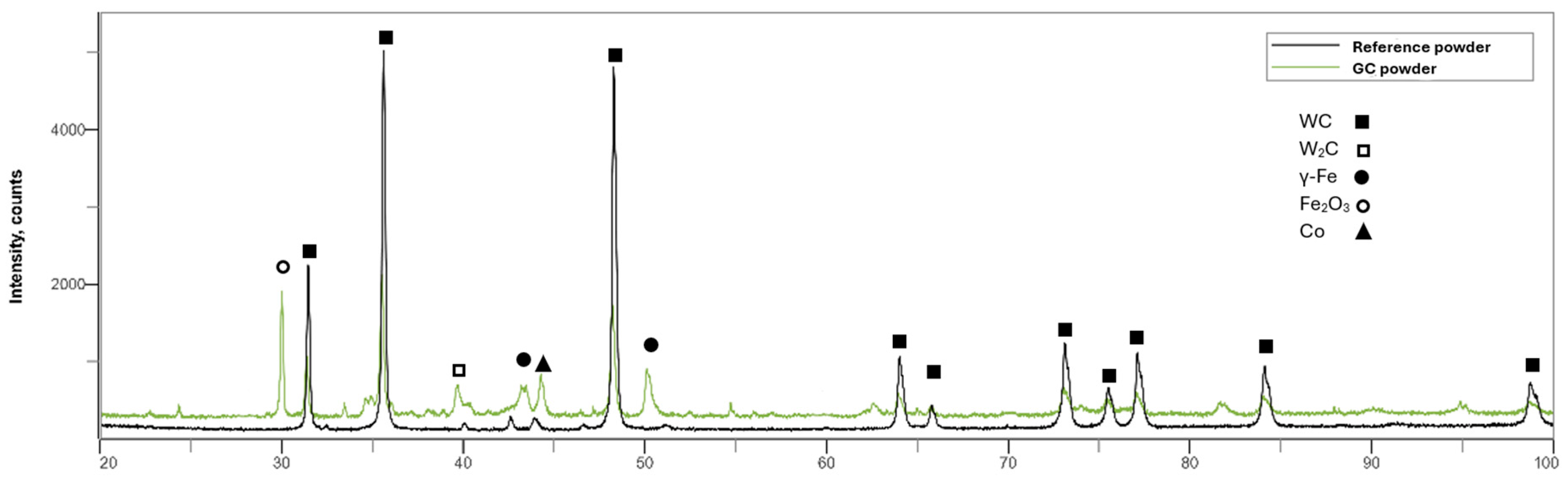
3.1. Particle Size Distribution and Powder Composition

The results of the particle size distribution are presented in Figure 1 as cumulative distribution curves. Additionally, the D90 values have been plotted here and marked accordingly in the curves.
Compared to the other powders the reference powder (dark green curve) shows a sharp increase between D10 and D90, indicating a narrow particle size distribution. This is also confirmed by the corresponding D10, D50, and D90 values. It is worth noting that the reference powder appears slightly coarser than originally specified by the manufacturer.
Measurements of the unsieved GC material in its as-received condition show a significantly flatter curve compared to that of the reference powder. The deviations are particularly substantial in the coarser particle size range. The WC-Co-Cr powder has a D90 value of 62.14 µm, whereas the unsieved GC powder has a value of 180.31 µm—over three times higher. In the finer particle size range, the deviation is considerably smaller.
Clearly demonstrating that both the cumulative distribution curve and the D50 and D90 values shift significantly towards those of the reference material, sieving the GC materials is an effective method. The D90 value of the sieved GC material is 81.67 µm, which is above the sieve mesh size. This suggests that the particles are not spherical and that agglomeration may have occurred, which could potentially distort the results (as the measurement represents an average of two diagonal lengths per particle).
This is further confirmed by the representative SEM image of the sieved GC material shown in Figure 2a.
It is evident that the examined powder contains a higher proportion of fine particles, which were not detectable in the previous measurement using the flowmeter. These fine particles tend to adhere either to each other or to larger particles.
The EDX analysis from Figure 2b reveals, in addition to the elements belonging to the cermet particles (C, W, Co, and Cr), further elements such as O, Ni, Al, Mo, and Fe. These oxides are marked as an example in Figure 2a.
For better comparability of the powders used, an XRD analysis was also carried out (see Figure 3).
The results show that there are significantly more phases in the GC powder. It also becomes clear that secondary carbides W2C are already present in the GC powder before coating.

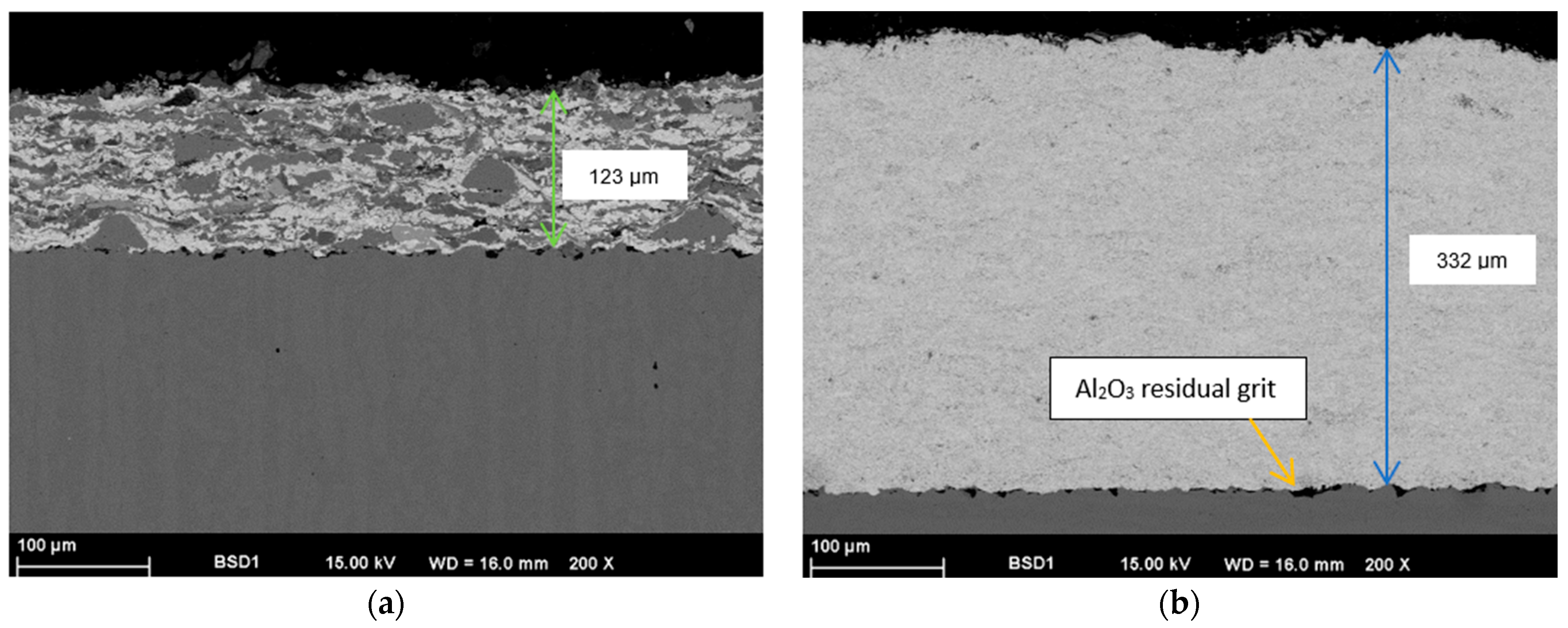
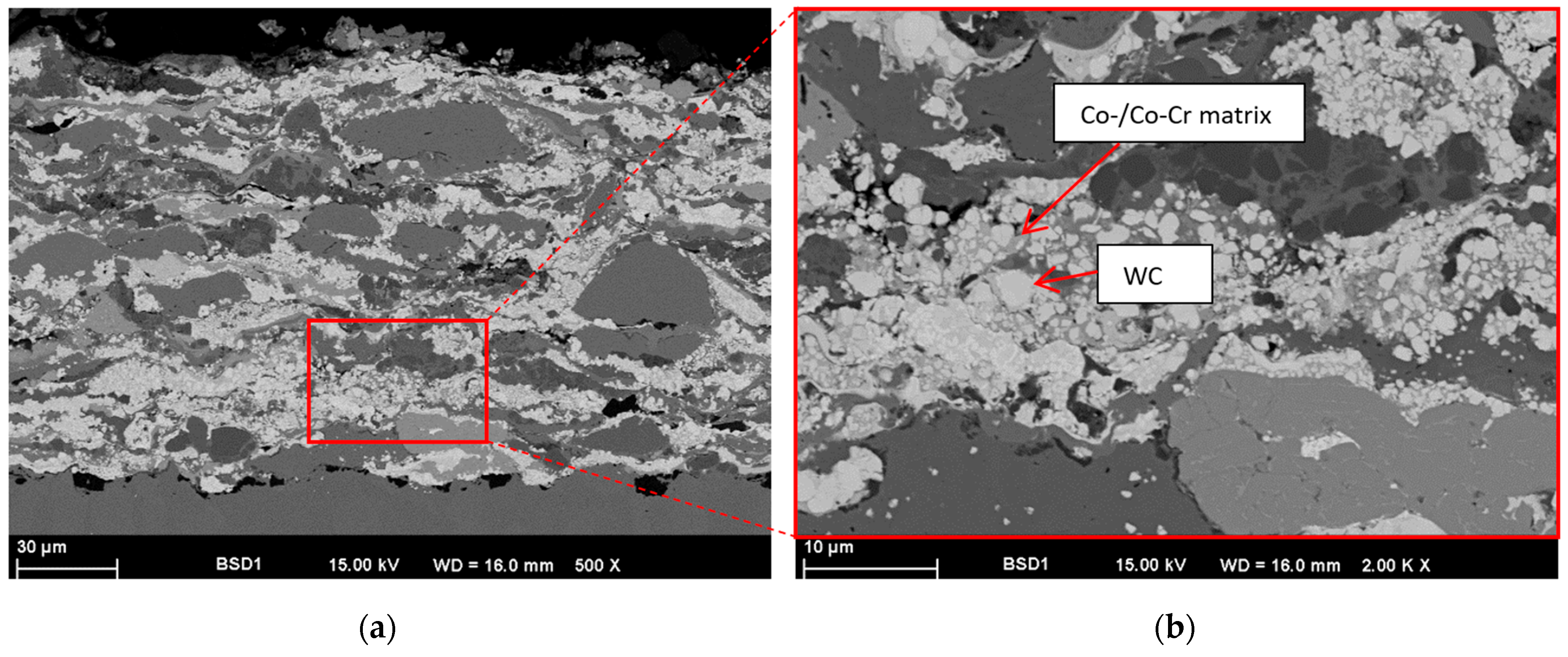
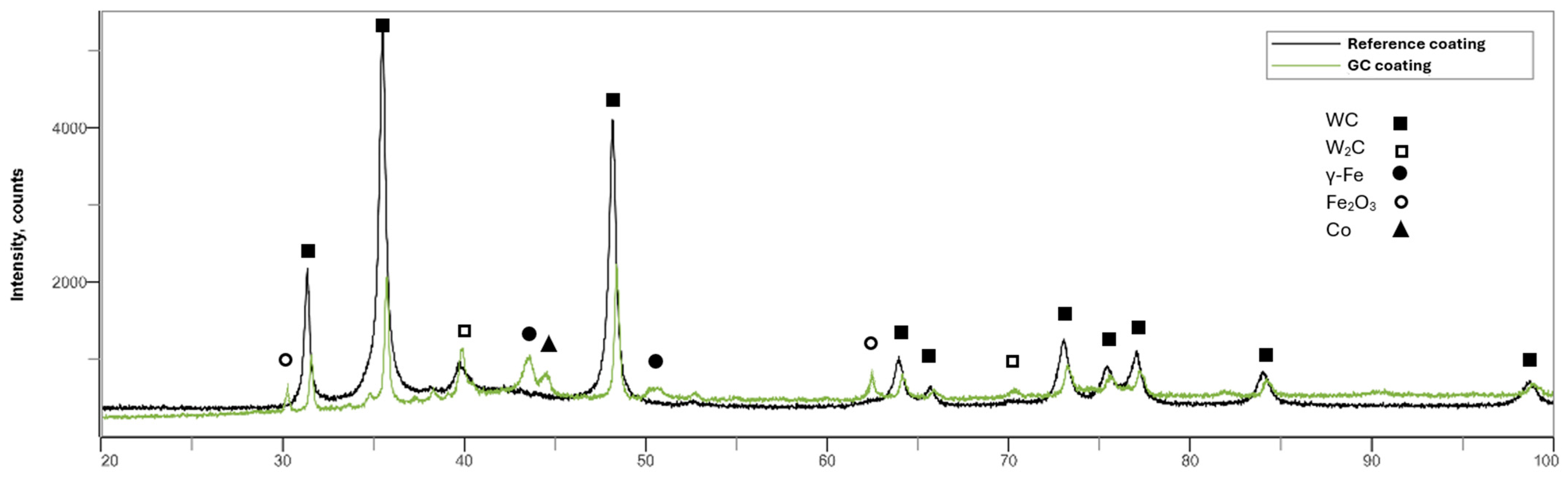
3.2. Microstructure of the Deposited Coatings

Figure 4 illustrates a comparison between the GC coating and the WC-Co-Cr reference coating in cross-section. It is distinctly apparent that the thickness of the reference coating is substantially greater than that of the GC coating. Additionally, the WC-Co-Cr layer reveals a distinctly more homogeneous microstructure. This suggests that the deposition efficiency of the reference coating is considerably superior in comparison with that of the GC coating.
Both coatings shown in Figure 4a,b are dense and do not delaminate when subjected to metallographically induced stresses. Therefore, they could be used in subsequent planned investigations. The black particles located at the interface between the coatings and the substrate originate from the substrate blasting (Al2O3).
Some microstructural features, in the context of microporosity or microcracks, were observed when the WC-Co-Cr coating was investigated at higher magnification (Figure 5). Furthermore, Figure 5b depicts the homogeneous distribution of the WC particles (light gray) in the metallic matrix (Co and Cr). Examination of the GC coating in cross-section at higher magnification revealed a heterogeneous microstructure in terms of both the chemical composition and the particle size, which is attributed to the initial powder material. Figure 6b provides clearer evidence of the presence of WC particles (light gray).
The EDX mapping shown in Figure 7 provides a clear picture of the distribution of the particles with different chemical composition, and thus the ratio of the cermet fraction (light gray) to the fraction of other metallic oxides (several dark gray scales).
At this point, both coatings examined were analyzed using XRD in order to better compare them with each other.
Figure 8 clearly shows that secondary carbides W2C have now also formed in the reference coating during coating. Nevertheless, there are still more phases in the GC coating than in the reference. The results therefore correlate well with the previous investigations.

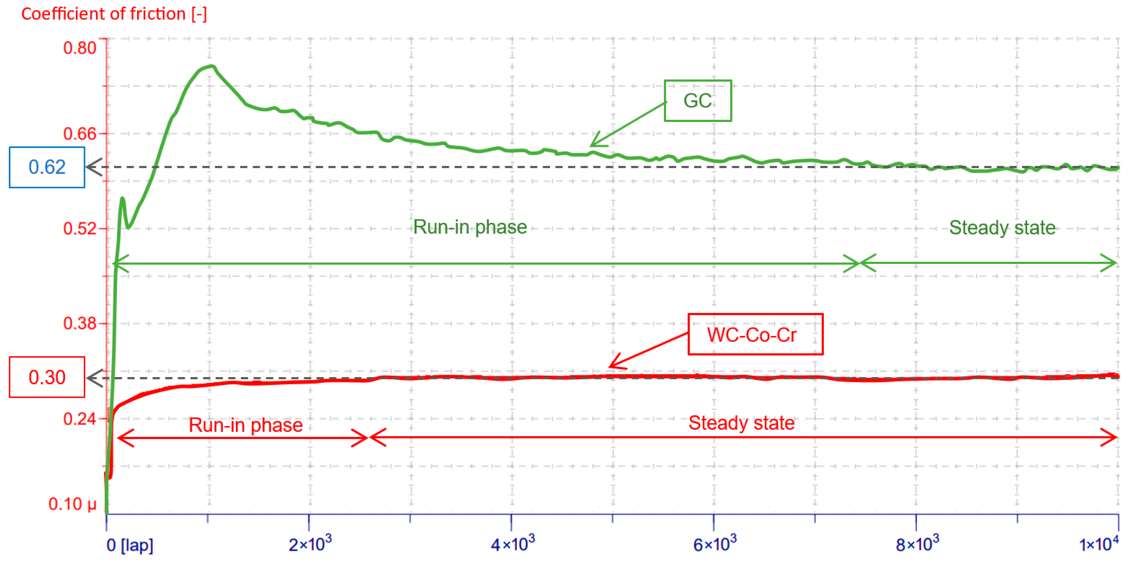
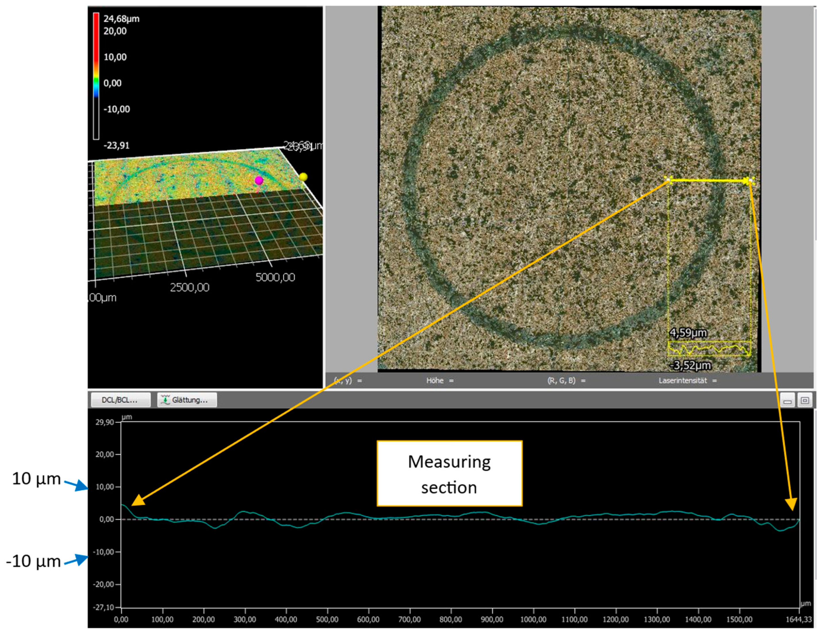
3.3. Mechanical and Tribological Properties

The results obtained from the hardness tests (Figure 9) also revealed some differences between the two types of coatings that can be correlated with their microstructure and the tendency to crack formation. The reference coating is significantly harder than the GC coating. This is due, on the one hand, to the higher WC content in the reference coating, and, on the other hand, to the heterogeneous particle size and composition of the GC coating. This also led to a larger variation in hardness.
The WC-Co-Cr coating exhibits significantly better resistance to crack formation and propagation under similar loading conditions to those of the GC coating (see Figure 10). As indicated by the red markings around the indentation region in Figure 10a, the crack development can be classified as non-critical. In contrast, the crack propagation in the GC coating must be considered critical. The cracks originate within the coating (cohesive failure) and extend beyond the indentation area.
A comparison of the values for the evolution of the coefficient of friction during the tribological tests (see Figure 11) shows that the GC coating has a significantly longer run-in phase than that of the reference coating (approximately 7500 laps compared to 2500 laps). Furthermore, the coefficient of friction curve of the GC coating consistently displays significantly higher values than that of the reference coating. The steady-state friction coefficient of the GC coating is over twice that of the reference coating. The increased friction resistance is due to the larger metal components in the GC coating. The cleaning coefficient between the ball and the metal components is significantly higher than, for example, with carbides.
The sliding wear behavior of the GC coating can be explained by its diverse chemical composition, which creates varying local conditions for the WC ball during testing. As a result, the green curve exhibits significantly more fluctuation compared to the red one.
Regardless of the measured values for the coefficient of friction, what is particularly noteworthy is that neither the WC-Co-Cr nor the GC coating exhibits any significant material loss. Figure 12 clearly shows that there is no notable difference in surface topography between the unexposed area and the wear track exposed to the test conditions in the yellow-marked measurement area.
As a result, it was not possible to determine the wear volume for either of the tested coating types, as no wear track depth was generated. Considering their mechanical and tribological properties, the GC coatings are significantly less hard and have poorer resistance to crack formation. Despite this, the GC coatings demonstrate similar resistance to sliding wear tests under the same conditions.

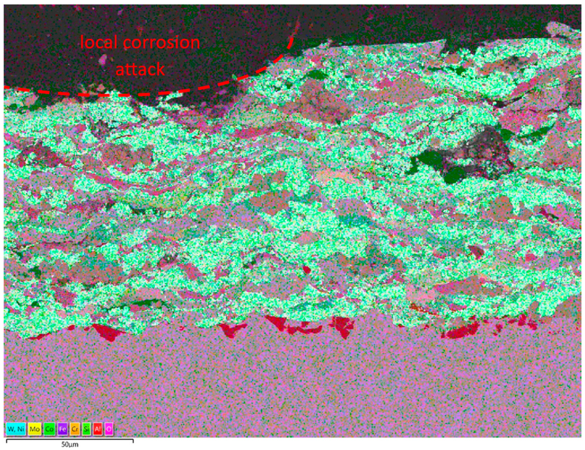
3.4. Corrosion Behavior

The semi-logarithmic plots of the current density–potential measurements (see Figure 13) show that the reference coatings tested in both solutions (Ref-M1 and Ref-M2) exhibit similar values for the determined current density (see Table 4), indicating similar kinetics of the corrosion reaction. However, reducing the pH value of the testing solution shifts the corrosion potential in a negative direction, allowing corrosion attack to initiate earlier (see Ref-M2).
A similar shift in the corrosion potential was also registered for the GC coatings when the pH value of the testing solution decreased. However, faster corrosion kinetics for the sample GC-M2 were indicated by an increase in the current density (icorr). The Ucorr values of the tested GC samples were lower than those of the WC-Co-Cr reference coatings. Furthermore, the corrosion current density values determined were higher than those of the reference samples. This indicates that the corrosion attack generally occurs earlier and proceeds with higher kinetics in the GC coatings.
Figure 14 presents a cross-section of one of the examined GC coatings after exposure to a 3.5% NaCl solution at pH 3.5 in order to assess the degree of corrosion attack more precisely.
Examining Figure 14 reveals a localized attack caused by pitting corrosion induced by Cl anions (marked in red). The main objective of this microscopic investigation was to determine whether the corrosion medium had penetrated the coating and reached the substrate. It was identified that the metallic areas (containing Fe) in the coating were more susceptible to corrosion attack. Based on the information provided by this SEM micrograph, it can be concluded that no corrosion attack was detected at the coating/substrate interface. Only aluminum oxide particles were observed in this region, as reported in the previous section (see Figure 7a). This suggests that corrosion resistance can still be assumed at this stage and that the GC coating is effective in providing a barrier.

4. Conclusions

This research project compared the wear and corrosion behavior of cermet coatings made from conventional WC-Co-Cr and recycled materials. As an alternative recycled cermet, filter dust from an HVOF system was used, consisting mainly of WC-Co and WC-Co-Cr, as well as various other components, such as metallic oxides. The recycled powder, belonging to the Green Cermets (GCs) group, was analyzed in terms of particle size distribution and sieved to improve its applicability. The sieving process filtered out significantly coarser particles, resulting in a distribution that approached that of the reference material. However, the sieved GC powder still contained a significant proportion of particles smaller than 10 µm. This resulted in greater heterogeneity in the microstructure of the coating concerning particle size. SEM/EDX analysis revealed the presence of elements such as Fe, Cr, Ni, Mo, and Al, mostly in oxidized form, in addition to the main component WC-Co-Cr/WC-Co.
Investigations of the mechanical properties showed that the hardness of the GC coating was significantly lower than that of the WC-Co-Cr coating. The measured hardness of the GC coating was 678 ± 55 HV, whereas that of the reference coating was 1042 ± 29 HV.
Additionally, critical cracking behavior was identified in the GC coating, with cracks extending well beyond the edges of the Brinell indentation areas. Once again, the heterogeneity of the chemical composition and particle size contributed to the reduced load-bearing capacity.
The wear tests indicated that the steady-state coefficient of friction for the GC coatings, at 0.62, was significantly higher than that for the WC-Co-Cr coating, for which the value was only 0.3. However, no measurable wear volume was detected for either coating. The WC wear ball only slid over the exposed carbides in the reference coatings but over carbides and oxides in the GC coatings.
The GC coatings exhibited lower corrosion resistance than the WC-Co-Cr coatings, regardless of the medium used.
Reducing the pH value increased the corrosion current density of the GC coating from 11 µmA/cm2 to 37.1 µA/cm2. In contrast, the WC-Co-Cr coatings showed no significant change in the corrosion current density. Even though the SEM images of the GC corrosion samples depicted localized corrosion at the coating surface (pitting corrosion), the interface with the substrate remained unaffected.
In general, it can be stated that the performance range of the GC coatings is significantly lower than that of conventional WC-Co-Cr coatings. Nevertheless, the wear and corrosion tests have demonstrated the potential of GCs for industrial applications.

Author Contributions

Conceptualization, D.W. and J.E.; methodology, D.W., J.E. and G.M.; software, D.W.; validation, D.W., J.E., I.-D.U. and G.M.; formal analysis, D.W., J.E., I.-D.U. and G.M.; investigation, D.W.; resources, D.W., J.E., I.-D.U. and G.M.; data curation, D.W.; writing—original draft preparation, D.W.; writing—review and editing, D.W., J.E., I.-D.U. and G.M.; visualization, D.W.; supervision, I.-D.U. and G.M.; project administration, D.W.; funding acquisition, I.-D.U. and G.M. All authors have read and agreed to the published version of the manuscript.

Funding

This research received no external funding.

Institutional Review Board Statement

Not applicable.

Informed Consent Statement

Not applicable.

Data Availability Statement

The data in this study is available on request from the authors. The data are not publicly available because they are part of ongoing studies.

Acknowledgments

The studies were performed during the Ph.D. program of the Doctoral School of the University Politehnica Timisoara in cooperation with the Westphalian University of Applied Sciences Gelsenkirchen Recklinghausen Bocholt. We acknowledge the support of Deniz Kurumlu in providing access to the Laboratory for Materials Science and Testing from Westfälische Hochschule Gelsenkirchen, Germany.

Conflicts of Interest

The authors declare no conflicts of interest.

References

  1. Zhao, X.; Li, C.; Li, S.; Han, X.; Liu, P. Mechanism evaluations of conventional and suspended HVOF thermal spraying based on EDC and EDM combustion models. Appl. Therm. Eng. 2024, 241, 122405. [Google Scholar] [CrossRef]
  2. Anusha, K.; Routara, B.C.; Guha, S. A review on High-Velocity Oxy-Fuel (HVOF) coating technique. J. Inst. Eng. (India) Ser. D 2023, 104, 831–848. [Google Scholar] [CrossRef]
  3. Jonda, E.; Łatka, L.; Godzierz, M.; Maciej, A. Investigations of microstructure and corrosion resistance of WC-Co and WC-Cr3C2-Ni coatings deposited by HVOF on magnesium alloy substrates. Surf. Coat. Technol. 2023, 459, 129355. [Google Scholar] [CrossRef]
  4. Zhao, X.; Li, C.; Li, S.; Han, X.; Jiang, H. Mechanism study on the influence of combustion models and spray gun geometric parameters on HVOF thermal spraying. J. Manuf. Process. 2023, 98, 178–185. [Google Scholar] [CrossRef]
  5. Pradeep, D.G.; Venkatesh, C.V.; Nithin, H.S. Review on tribological and mechanical behavior in HVOF thermal-sprayed composite coatings. J. Bio- Tribo-Corros. 2022, 8, 30. [Google Scholar] [CrossRef]
  6. Zhao, X.; Li, C.; Li, S.; Jiang, H.; Han, X. Time-varying evolutionary mechanism analysis of the multiphase flow during HVOF thermal spraying WC-12Co particle. Surf. Coat. Technol. 2023, 461, 129435. [Google Scholar] [CrossRef]
  7. Saharkhiz, R.; Valefi, Z.; Mirjani, M.; Mirak, A. Comprehensive study on the effect of HVOF processing parameters and particle size on high-temperature properties of NiCoCrAlYTa coatings. Surf. Coat. Technol. 2023, 473, 129951. [Google Scholar] [CrossRef]
  8. Feizabadi, A.; Salehi Doolabi, M.; Sadrnezhaad, S.K.; Rezaei, M. Cyclic oxidation characteristics of HVOF thermal-sprayed NiCoCrAlY and CoNiCrAlY coatings at 1000 °C. J. Alloys Compd. 2018, 746, 509–519. [Google Scholar] [CrossRef]
  9. Russell, Z.; Gaier, M.; Froning, M.J.; Plucknett, K.P. The aqueous corrosion and wear responses of HVOF-deposited TiC-Ni3Al, WC-Co, and WC-CoCr coatings on AISI 4130 steel substrates. Surf. Coat. Technol. 2023, 473, 130018. [Google Scholar] [CrossRef]
  10. Picas, J.A.; Forn, A.; Matthäus, G. HVOF coatings as an alternative to hard chrome for pistons and valves. Wear 2006, 261, 477–484. [Google Scholar] [CrossRef]
  11. Lakshmi, D.V.; Babu, P.S.; Alroy, R.J.; Kumar, G.S.; Prasad, M.J.N.V. Performance Evaluation of Thin Cermet Coatings Produced by HVAF Spray: A New Approach for Hard Chrome Replacement. J. Therm. Spray. Tech. 2023, 32, 904–917. [Google Scholar] [CrossRef]
  12. Prasad, C.D.; Soni, P.K.; Nagaraja, K.C.; Eswaran, A.; Kumar, S.R.; Deshmukh, K.; Shrivastava, R.; Tiwari, A. Studies on wear and microstructure assessment of WC-Co reinforced iron based HVOF coating. Results Surf. Interfaces 2024, 15, 100237. [Google Scholar] [CrossRef]
  13. Cao, S.; Chang, Z.; Li, S.; Zhang, W.; Xu, S. Effect of binder phases on the microstructure and sliding wear properties of HVOF-sprayed WC-based coatings. Int. J. Refract. Met. Hard Mater. 2024, 122, 106742. [Google Scholar] [CrossRef]
  14. Lekatou, A.G.; Sioulas, D.; Grimanelis, D. Corrosion and wear of coatings fabricated by HVOF-spraying of nanostructured and conventional WC–10Co-4Cr powders on Al7075-T6. Int. J. Refract. Met. Hard Mater. 2023, 112, 106164. [Google Scholar] [CrossRef]
  15. Baumann, I.; Hagen, L.; Tillmann, W.; Hollingsworth, P.; Stangier, D.; Schmidtmann, G.; Tolan, M.; Paulus, M.; Sternemann, C. Process characteristics, particle behavior and coating properties during HVOF spraying of conventional, fine and nanostructured WC-12Co powders. Surf. Coat. Technol. 2021, 405, 126716. [Google Scholar] [CrossRef]
  16. Gallego, M.; Chávez, S.C.; De La Roche, J.; Toro, A. Effect of heat treatment on the wet abrasion resistance of WC-10Co4Cr coatings deposited onto stainless steel by HVOF. Tribol. Mater. Surf. Interfaces 2022, 16, 168–176. [Google Scholar] [CrossRef]
  17. Mi, P.; Wang, T.; Ye, F. Influences of the compositions and mechanical properties of HVOF sprayed bimodal WC-Co coating on its high temperature wear performance. Int. J. Refract. Met. Hard Mater. 2017, 69, 158–163. [Google Scholar] [CrossRef]
  18. Geng, Z.; Li, S.; Duan, D.L.; Liu, Y. Wear behaviour of WC–Co HVOF coatings at different temperatures in air and argon. Wear 2015, 330–331, 348–353. [Google Scholar] [CrossRef]
  19. Rúa Ramirez, E.; Silvello, A.; Torres Diaz, E.; Tornese, F.; Gnoni, M.G.; Cano, I.G. A comparison of cold spray, atmospheric plasma spray and high velocity oxy fuel processes for WC-Co coatings deposition through LCA and LCCA. Heliyon 2024, 10, e38961. [Google Scholar] [CrossRef]
  20. Agnihotri, A.; Vasudev, H.; Singh, G.; Singh, S.; Hosalli, R.; Veeresha, G.; Prasad, C.D.; Balu, R.; Tiwari, A. Evaluation of HVOF sprayed and burnished WC-Co-Cr coatings on boiler steel: Mechanical and microstructural properties. J. Bio- Tribo-Corros. 2025, 11, 50. [Google Scholar] [CrossRef]
  21. Owoseni, T.A.; Gupta, M.; Joshi, S.V.; Ingmar, M.; Varis, T. Wear and Corrosion of HVAF and HVOF-Sprayed WC-CoCr Coatings on Aluminum Alloy. J. Therm. Spray. Tech. 2025, 34, 970–991. [Google Scholar] [CrossRef]
  22. Zhou, Y.; Liu, X.; Kang, J.; Yue, W.; Qin, W.; Ma, G.; Fu, Z.; Zhu, L.; She, D.; Wang, H.; et al. Corrosion behavior of HVOF sprayed WC-10Co4Cr coatings in the simulated seawater drilling fluid under the high pressure. Eng. Fail. Anal. 2020, 109, 104338. [Google Scholar] [CrossRef]
  23. Ghosh, G.; Sidpara, A.; Bandyopadhyay, P.P. Theoretical analysis of magnetorheological finishing of HVOF sprayed WC-Co coating. Int. J. Mech. Sci. 2021, 207, 106629. [Google Scholar] [CrossRef]
  24. Pulsford, J.; Venturi, F.; Pala, Z.; Kamnis, S.; Hussain, T. Application of HVOF WC-Co-Cr coatings on the internal surface of small cylinders: Effect of internal diameter on the wear resistance. Wear 2019, 432–433, 202965. [Google Scholar] [CrossRef]
  25. Bolelli, G.; Colella, A.; Lusvarghi, L.; Morelli, S.; Puddu, P.; Righetti, E.; Sassatelli, P.; Testa, V. TiC–NiCr thermal spray coatings as an alternative to WC-CoCr and Cr3C2–NiCr. Wear 2020, 450–451, 203273. [Google Scholar] [CrossRef]
  26. Pereira, P.; Vilhena, L.M.; Sacramento, J.; Senos, A.M.R.; Malheiros, L.F.; Ramalho, A. Abrasive wear resistance of WC-based composites, produced with Co or Ni-rich binders. Wear 2021, 482–483, 203924. [Google Scholar] [CrossRef]
  27. Picas, J.A.; Menargues, S.; Martin, E.; Baile, M.T. Cobalt free metallic binders for HVOF thermal sprayed wear resistant coatings. Surf. Coat. Technol. 2023, 456, 129243. [Google Scholar] [CrossRef]
  28. Tegelkamp, L.; Grimm, M.; Conze, S.; Berger, L.-M.; Lindner, T.; Lampke, T. Microstructure and wear resistance of environmentally friendly NbC-FeCr coatings: An evaluation of HVOF process parameters. Surf. Coat. Technol. 2025, 509, 132208. [Google Scholar] [CrossRef]
  29. Torkashvand, K.; Joshi, S.; Gupta, M. Advances in thermally sprayed WC-based wear-resistant coatings: Co-free binders, processing routes and tribological behavior. J. Therm. Spray Technol. 2022, 31, 342–377. [Google Scholar] [CrossRef]
  30. Mishra, D.; Sinha, S.; Sahu, K.K.; Agrawal, A.; Kumar, R. Recycling of secondary tungsten resources. Trans. Indian Inst. Met. 2017, 70, 479–485. [Google Scholar] [CrossRef]
  31. Chen, Y.; Huo, G.; Guo, X.; Wang, Q. Sustainable extraction of tungsten from the acid digestion product of tungsten concentrate by leaching-solvent extraction together with raffinate recycling. J. Clean. Prod. 2022, 375, 133924. [Google Scholar] [CrossRef]
  32. Liang, J.J.; Geng, Y.; Zeng, X.L.; Gao, Z.Y.; Tian, X. Toward sustainable utilization of tungsten: Evidence from dynamic substance flow analysis from 2001 to 2019 in China. Resour. Conserv. Recycl. 2022, 182, 106307. [Google Scholar] [CrossRef]
  33. Varis, T.; Lagerbom, J.; Suhonen, T.; Raami, L.; Terho, S.; Laurila, J.; Peura, P.; Vuoristo, P. Effect of heat treatments on the wear resistance of HVAF and HVOF sprayed tool steel coatings. Surf. Coat. Technol. 2023, 462, 129508. [Google Scholar] [CrossRef]
  34. Kumar, R.; Kariminejad, A.; Antonov, M.; Goljandin, D.; Klimczyk, P.; Hussainova, I. Progress in sustainable recycling and circular economy of tungsten carbide hard metal scraps for Industry 5.0 and onwards. Sustainability 2023, 15, 12249. [Google Scholar] [CrossRef]
  35. Gislev, M.; Grohol, M.; Mathieux, F.; Ardente, F.; Bobba, S.; Nuss, P.; Blengini, G.; Alves Dias, P.; Blagoeva, D.; Matos, C.; et al. Report on Critical Raw Materials and the Circular Economy; European Commission: Brussels, Belgium, 2018; pp. 1–76. [Google Scholar]
  36. Zeiler, B.; Bartl, A.; Schubert, W.-D. Recycling of tungsten: Current share, economic limitations, technologies and future potential. Int. J. Refract. Met. Hard Mater. 2021, 98, 105546. [Google Scholar] [CrossRef]
  37. Liang, J.; Geng, Y.; Su, C.; Chen, W. An emergy-based comparison between primary and secondary tungsten production in China. Environ. Impact Assess. Rev. 2024, 107, 107548. [Google Scholar] [CrossRef]
  38. Pacini, A.; Lupi, F.; Rossi, A.; Seggiani, M.; Lanzetta, M. Direct recycling of WC-Co grinding chip. Materials 2023, 16, 1347. [Google Scholar] [CrossRef]
  39. Mégret, A.; Vitry, V.; Delaunois, F. Study of the processing of a recycled WC–Co powder: Can it compete with conventional WC–Co powders? J. Sustain. Metall. 2021, 7, 448–458. [Google Scholar] [CrossRef]
  40. Varis, T.; Suhonen, T.; Jokipii, M.; Vuoristo, P. Influence of powder properties on residual stresses formed in high-pressure liquid fuel HVOF sprayed WC-CoCr coatings. Surf. Coat. Technol. 2020, 388, 125604. [Google Scholar] [CrossRef]
  41. Tillmann, W.; Kuhnt, S.; Baumann, I.T.; Kalka, A.; Becker-Emden, E.-C.; Brinkhoff, A. Statistical comparison of processing different powder feedstock in an HVOF thermal spray process. J. Therm. Spray Technol. 2022, 31, 1476–1489. [Google Scholar] [CrossRef]
  42. Viswanathan, V.; Katiyar, N.K.; Goel, G.; Matthews, A.; Goel, S. Role of thermal spray in combating climate change. Emergent Mater. 2021, 4, 1515–1529. [Google Scholar] [CrossRef]
  43. Silvello, A.; Cavaliere, P.; Yin, S.; Lupoi, R.; Garcia Cano, I.; Dosta, S. Microstructural, mechanical and wear behavior of HVOF and cold-sprayed high-entropy alloys (HEAs) coatings. J. Therm. Spray Technol. 2022, 31, 1184–1206. [Google Scholar] [CrossRef]
Figure 1. Representative cumulative curves of the particle size distribution measurement for the reference and GC powders (sieved and unsieved).
Applsci 15 07654 g001
Figure 2. (a) SEM micrograph of the sieved GC powder; (b) EDX analysis of the GC powder (Au-sputtered).
Applsci 15 07654 g002
Figure 3. XRD diffractograms of the reference powder WC-Co-Cr and the GC powder.
Applsci 15 07654 g003
Figure 4. SEM/BSD micrographs in cross-section: (a) GC coating; (b) WC-Co-Cr reference coating.
Applsci 15 07654 g004
Figure 5. SEM/BSD micrographs of the WC-Co-Cr coating in cross-section at higher magnification: (a) 500×; (b) 2000×.
Applsci 15 07654 g005
Figure 6. SEM/BSD micrographs of the GC coating in cross-section at higher magnification: (a) 500×; (b) 2000×.
Applsci 15 07654 g006
Figure 7. EDX mapping of the GC coating in cross-section (a) and the corresponding EDX analysis (b).
Applsci 15 07654 g007
Figure 8. XRD diffractograms of the reference coating WC-Co-Cr and the GC coating.
Applsci 15 07654 g008
Figure 9. Bar chart showing the mean values and standard deviations for the HV1 hardness measurement of the investigated coatings.
Applsci 15 07654 g009
Figure 10. Representative CLSM image at 50× magnification of the crack propagation test (HB; Ø 2.5 mm; test load = 62.5 kp) of (a) the WC-Co-Cr coating and (b) the GC coating.
Applsci 15 07654 g010
Figure 11. Coefficient of friction curves of the GC (green) and WC-Co-Cr (red) coatings using WC as the counter body.
Applsci 15 07654 g011
Figure 12. Exemplary CLSM 3D scan of the wear track on the GC coating at R = 3 mm.
Applsci 15 07654 g012
Figure 13. Semi-logarithmic current density–potential curves of GC and WC-Co-Cr (Ref.) in M1: 3.5% NaCl solution and M2: 3.5% NaCl solution at pH 3.5 (with HCl).
Applsci 15 07654 g013
Figure 14. Cross-section SEM image of the GC coating after corrosion in 3.5% NaCl at pH 3.5.
Applsci 15 07654 g014
Table 1. Details regarding the settings and measurements of particle size measurement.
Measurement DetailsSetting
Pump output 100%
Ultrasound for dispersion on
Medium Distilled water
Dispersion time 1 min
Images captured 30,000
Pump power 100%
Table 2. Coating parameters.
ParameterSettings
Oxygen flow rate [L/min] 665
Spraying distance [mm] 280
Kerosene flow rate [L/min] 0.35
Carrier gas N2 [L/min] 11.0
Powder feed rate [g/min] 85
Differential velocity burner/substrate [m/s] 90
Coating cycles 3
Passes per coating cycle 5
Table 3. POD test parameters.
ParameterValue
Load [N] 10
Linear speed [cm/s] 10
Wear track diameter [mm] 6
Laps [-] 10,000
Stop condition [-] laps
Lubricant [-] none
Temperature [°C] 22
Ball material [-] WC-Co
Ball diameter [mm] 6
Table 4. Corrosion current density and corrosion potential.
SampleUcorr [mV]icorr [µA/cm2]
GC-M1−401 ± 2411.0 ± 2.3
GC-M2−394 ± 2137.1 ± 3.1
Ref-M1−171 ± 135.9 ± 0.8
Ref-M2−273 ± 156.6 ± 0.7
Disclaimer/Publisher’s Note: The statements, opinions and data contained in all publications are solely those of the individual author(s) and contributor(s) and not of MDPI and/or the editor(s). MDPI and/or the editor(s) disclaim responsibility for any injury to people or property resulting from any ideas, methods, instructions or products referred to in the content.

