Abstract
Stationary inverse-geometry digital tomosynthesis (s-IGDT) causes truncation artifacts in reconstructed images due to its geometric characteristics. This study introduces a deep convolutional generative adversarial network (DCGAN)-based out-painting method for mitigating truncation artifacts in s-IGDT images. The proposed network employed an encoder–decoder architecture for the generator, and a dilated convolution block was added between the encoder and decoder. A dual-discriminator was used to distinguish the artificiality of generated images for truncated and non-truncated regions separately. During network training, the generator was able to selectively learn a target task for the truncated regions using binary mask images. The performance of the proposed method was compared to conventional methods in terms of signal-to-noise ratio (SNR), normalized root-mean-square error (NRMSE), peak SNR (PSNR), and structural similarity (SSIM). The results showed that the proposed method led to a substantial reduction in truncation artifacts. On average, the proposed method achieved 62.31, 16.66, and 14.94% improvements in the SNR, PSNR, and SSIM, respectively, compared to the conventional methods. Meanwhile, the NRMSE values were reduced by an average of 37.22%. In conclusion, the proposed out-painting method can offer a promising solution for mitigating truncation artifacts in s-IGDT images and improving the clinical availability of the s-IGDT.
1. Introduction
Digital tomosynthesis (DT) enables accurate diagnosis compared with traditional 2D radiography due to its superior depth resolution [1]. In addition, the DT can reduce the radiation dose compared to computed tomography (CT) owing to its limited-angle scanning strategy [2]. Despite these benefits, conventional DT systems suffer from mechanical complexity and low efficiency due to the physical movements of the X-ray source and detector. Also, these physical movements introduce motion artifacts in reconstructed images. Thus, there is a need to simplify the geometry of the DT system while maintaining its strengths. In particular, the geometric inversion with a small detector in the DT system allows more efficient diagnosis, image guidance, and radiation dose reduction by minimizing the field-of-view (FOV) relative to the conventional DT systems [3].
Recently, stationary inverse-geometry digital tomosynthesis (s-IGDT) has been proposed by using the geometric inversion with a stationary X-ray source array and a small detector. Several studies demonstrated that the s-IGDT can overcome the drawbacks of the conventional DT and, consequently, improve examination efficiencies [3,4,5]. The use of carbon nanotube-based X-ray source arrays within this system further enabled ultra-fast scans for the imaging [5]. In spite of the benefits of the s-IGDT, the stationary-small detector of the s-IGDT system introduces truncation effects in projections due to a limited FOV. This effect leads to the artifacts in reconstructed images, which appear as stepped bands and are parallel to the scan direction. The truncation artifacts are sensitive to scan range and the number of focal spots because truncated areas in projections can be varied by those factors [6,7,8]. These drawbacks degrade the quality of the s-IGDT image and reduce diagnostic accuracy. Therefore, developing a method for mitigating the truncation artifacts is essential to fully leverage the clinical potential of the s-IGDT.
With the advance of deep learning-based technologies, generative adversarial networks (GANs) have been used for various applications in the field of computer vision [9,10,11]. The imaging models based on the GANs are generally generated by the hostile training of the generator and the discriminator, and they showed a remarkable performance in predicting missing data and synthesizing realistic textures. Also, several studies reported that the GAN-based networks can reduce metal artifacts and improve image quality for DT images [12,13]. In this work, we introduced a deep convolutional GAN (DCGAN)-based out-painting method for alleviating the truncation artifacts in the s-IGDT images. While the GAN-based in-painting methods have been widely utilized for recovering image quality [11,14,15], the out-painting based on the GAN is relatively under-researched due to its practical challenge. The GAN-based in-painting model fills in partial image regions with pixel values, which are predicted by using the neighboring pixels located on all sides. In other words, the in-painting model is able to recover an image with sufficient information in a coherent way. The out-painting is conceptually similar to the in-painting. However, the out-painting task is imposed to create new image contents with insufficient information because the neighboring pixels around missing image regions are fewer than those used for the in-painting task. This phenomenon is more noticeable with an increase in missing image regions, and moreover, it may cause the artificiality and inaccuracy of recovered images.
In the proposed out-painting method, a dilated convolutional block was added to the DCGAN to provide the contextual information in diverse receptive fields, which is used for restoring the truncated regions of s-IGDT projections, during network training. A generator was designed with an encoder–decoder structure for generating plausible output images and leading to stable network training. Also, a dual-discriminator architecture was applied to the DCGAN for deriving the precise training of the generator and rejecting the artificiality of restored s-IGDT projections. Binary mask images were utilized for isolating truncated regions from non-truncated regions in an input projection. The sub-discriminators were separately optimized by using the out-painted and non-truncated regions of the generated images. The performance of the proposed out-painting method was compared with a conventional out-painting method by analyzing the noise property and quantitative accuracy of s-IGDT images.
2. Materials and Methods
2.1. s-IGDT System
An IGDT system was simulated for image guidance applications in surgical procedures. The system, illustrated in Figure 1, incorporated a linear X-ray source array and a small detector. Referring to a commercial X-ray source array (NuRay Technology Co., Ltd., Changzhou, China), the linear X-ray source array was designed to have multiple focal spots, which were arranged along an x-axis with identical distance intervals. The central X-ray beams emitted at each focal spot are directed through the center of the object, and each X-ray beam fully covers a detector under given geometries. The linear X-ray source array was modeled with lengths of 660, 990, and 1320 mm for evaluating the effect of scan ranges on truncation artifacts in s-IGDT images. Also, the numbers of focal spots in the linear X-ray source array were adjusted to 21, 41, and 81, respectively, to consider the various distributions of truncation artifacts. The s-IGDT scans were implemented with the reference condition of a 1320 mm length array or 21 focal spots in order to reflect the variation in a single factor on s-IGDT images. The detector was based on Rad-Xcam RT1763 (TELEDYNE DALSA, Waterloo, ON, Canada) with a size of 170 × 170 mm2. The pixel size was scaled by a factor of three compared to the real model to reduce simulation time. We also designed a virtual detector with a size of 340 × 170 mm2 for acquiring ground-truth (GT) projections without truncation in a region of interest (ROI). The distance from the X-ray source array to the object center was set to 1207 mm, and the source-to-detector distance was fixed at 1348.8 mm. A summary of the simulation parameters for the s-IGDT system is presented in Table 1.

Figure 1.
A schematic view of the simulated s-IGDT system consisted of the linear X-ray source array and a small detector. The truncation caused by a limited FOV was also presented in the figure.

Table 1.
Parameters of the simulated s-IGDT system used for obtaining images. * represents the reference condition.
2.2. Data Acquisition
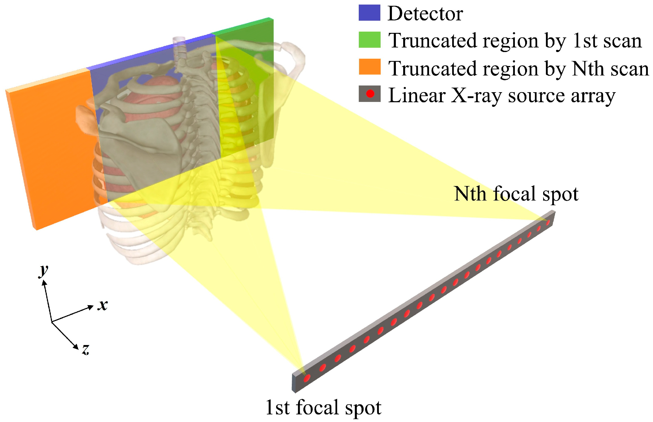
70 digital phantoms with an array of 512 × 292 × 512 were constructed by using the publicly available SPIE-AAPM Lung CT Challenge dataset [16]. This dataset comprises tens of thousands of clinical lung CT images for different patients, and the CT images were acquired under the scanning conditions of 120–140 kVp tube voltages, 240–389 mAs tube currents, and 1 mm slice thickness. Among the digital phantoms, 69 phantoms were allocated for training data preparation, and the remaining one was allocated for test data preparation. Figure 2 presents a coronal view of the test phantom with the ROI, which was scanned by the simulated s-IGDT system. The projections of each digital phantom were acquired by using the ray-driven forward projection model, which was designed in accordance with the geometry of the simulated s-IGDT system [17]. Both the linear X-ray source array and detector were stationary during the projection acquisition. A total of 20,020 projections were obtained, and among them, 19,734 and 286 projections were used for training and testing the proposed out-painting model, respectively.
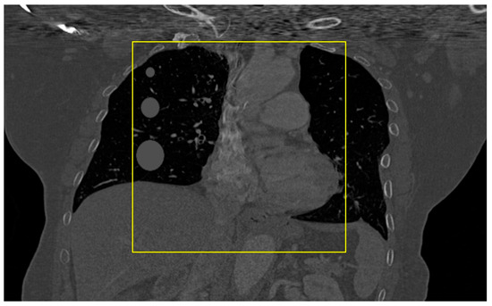
Figure 2.
Coronal view of the digital phantom, which was used for preparing test data. The yellow box is the region scanned by the simulated s-IGDT system.
2.3. Network Architecture
The proposed out-painting network architecture was derived from the foundational design of the DCGAN [18]. Typically, the DCGAN generator employs a series of transposed convolutional layers for progressively up-sampling an input image, and each layer includes batch normalization and activation functions to enhance training stability and convergence speed. In this work, the generator of the proposed out-painting network was designed with an encoder–decoder architecture for predicting missing data in s-IGDT projections, as shown in Figure 3.
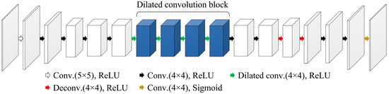
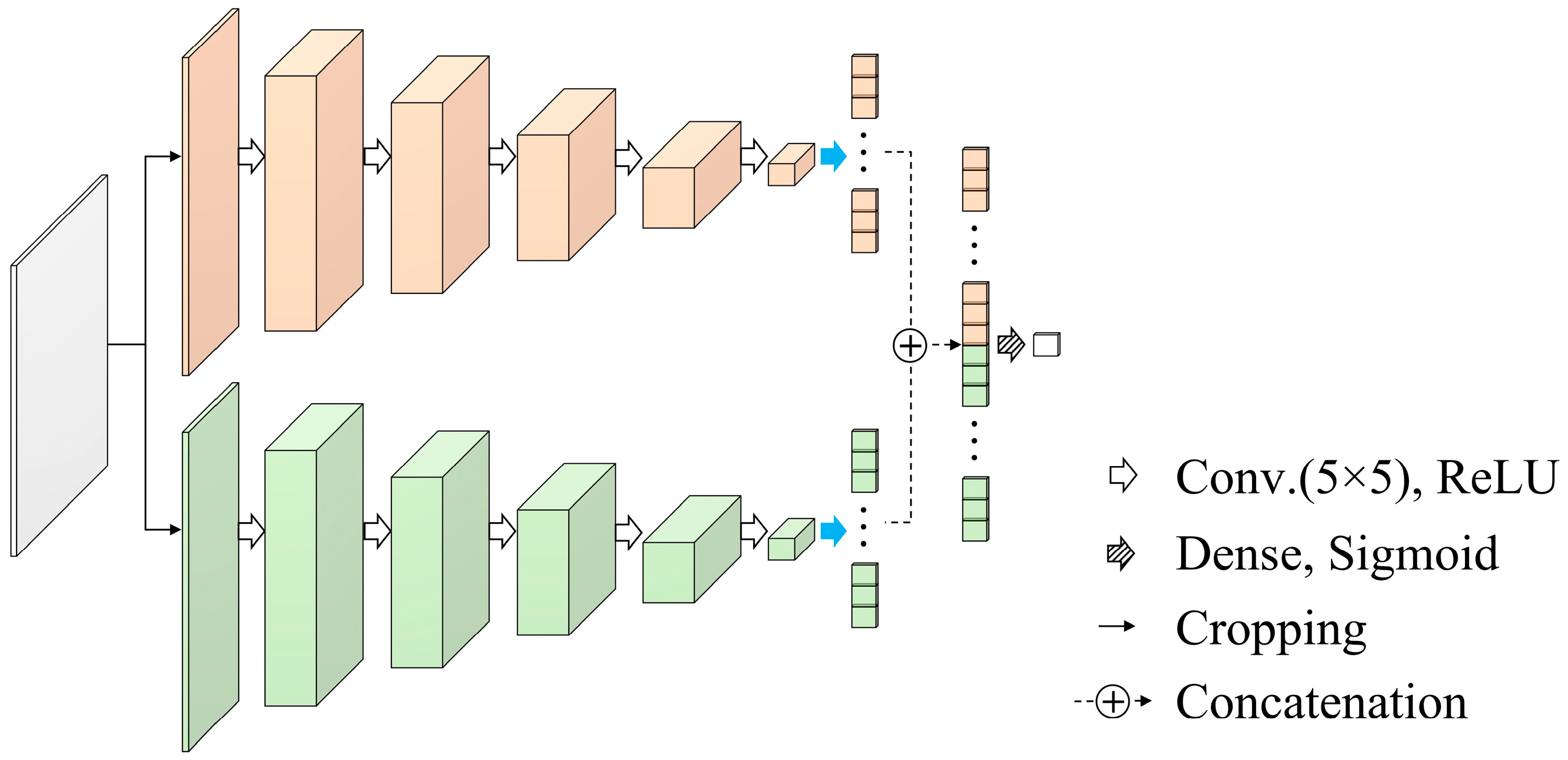
Figure 3.
Architecture of the generator in the proposed out-painting network.
Unlike the simple decoder architecture, which is generally used as the DCGAN generator, the encoder–decoder architecture allows for more controlled generation and makes it easier to produce plausible output images because the complex and latent features of input images can be selectively extracted by the encoder structure [19,20]. Moreover, the dimensionality reduction achieved by using the encoder structure is able to improve the training efficiency. By focusing on selective features for image generation, the encoder–decoder architecture can mitigate the mode collapse issue, which is common in the DCGAN, having a simple decoder architecture-based generator [21]. The encoder of the generator in the proposed out-painting network comprised 5 convolution layers with 4 × 4–5 × 5 kernel sizes and rectified linear unit (ReLU) activation function. The decoder of the generator consisted of 4 convolution layers with a ReLU activation function, 2 deconvolution layers with a ReLU activation function, and 1 convolution layer with a sigmoid activation function. We added the dilated convolution block, which comprised 4 dilated convolution layers with different dilation rates, for connecting the encoder to the decoder. The out-painting task suffers from a lack of learnable data because the image pixels adjacent to missing image regions are fewer than those used for the in-painting task. This fundamental issue can be resolved by providing the learnable data from dilated receptive fields. Compared to the standard convolution layer, features can be extracted from a large image area in the dilated convolution layer because the dilated convolution expands a receptive field. This characteristic of the dilated convolution allows the provision of sufficient information for the out-painting task. The dilated convolution enables a network to aggregate the contextual information of input features during training by using diverse receptive fields. Additionally, the zero-padding in convolution kernels used for dilating receptive fields can prevent the degradation of image resolution [22]. These benefits are able to generate precise output images, and valuable image features for the out-painting can be delivered by dilated receptive fields. Note that dilation rates were empirically determined to ensure acceptable image quality. The configuration of the generator is detailed in Table 2.
Table 2.
Detailed configuration of the generator used for the proposed out-painting network.
The discriminator of the DCGAN plays a key role in determining whether a generated image is real or fake [18]. In the s-IGDT image, non-truncated regions should maintain the features of input images, and the generated image for truncated regions should harmonize with surrounding regions through the discrimination procedure. But, the single discriminator used in conventional GAN-based networks makes it hard to distinguish the artificiality of each region in a generated image because the training of the single discriminator is implemented by using all areas of the generated image. In this work, a dual-discriminator was utilized for maintaining the consistency of input images and ensuring the plausibility of out-painted regions, as shown in Figure 4. Each sub-discriminator had 5 convolution layers with a ReLU activation function and 1 flatten layer, and the sub-discriminators shared 1 cropping layer, 1 concatenation layer, and 1 dense layer. The cropping layer divided a generated image into out-painted and non-truncated regions using the input image of the generator. The divided regions were separately processed by the sub-discriminators during network training. This strategy enables to reduction of the deformation of non-truncated regions and improves the reality of out-painted regions because the sub-discriminators were independently optimized for discriminating each region. The outputs from both the sub-discriminators were merged and compressed via the concatenation and dense layers for binary classification. A detailed summary of the discriminator architecture is presented in Table 3.
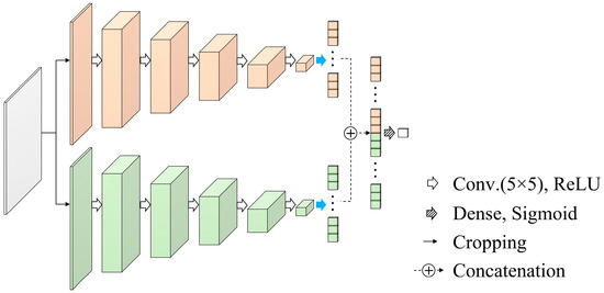
Figure 4.
Architecture of the discriminator in the proposed out-painting network.
Table 3.
Detailed configuration of the dual-discriminator used for the proposed out-painting network.
2.4. Network Training
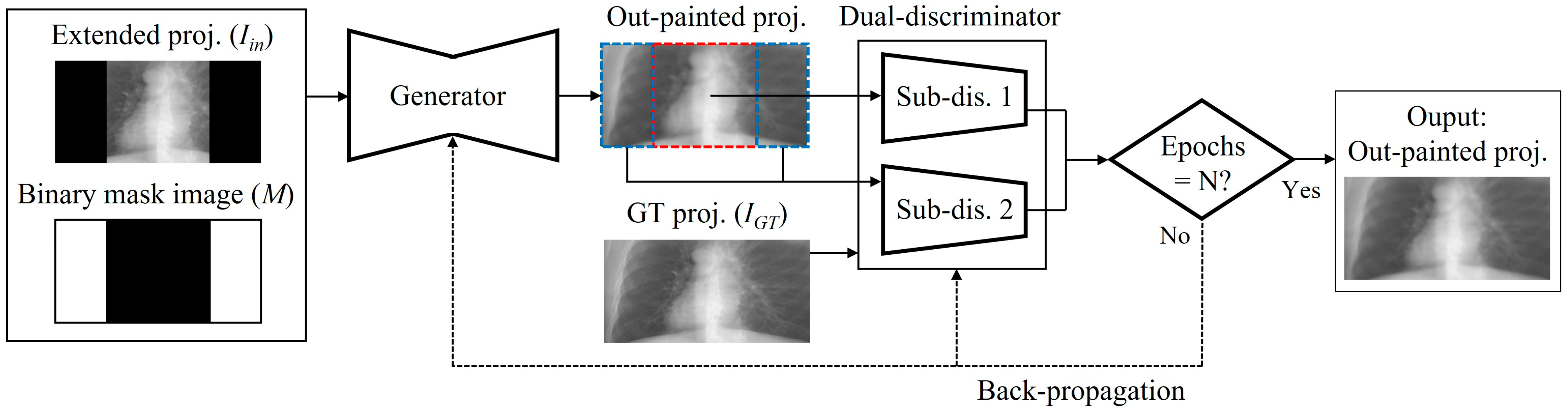
The workflow of network training is shown in Figure 5. The truncated projections were extended to the size of the GT projections by using zero-padding. Also, we prepared the binary mask images, which can differentiate between truncated and non-truncated regions in a projection domain. The binary mask images were straightforwardly derived from the geometric layout and scan conditions of the s-IGDT system. The extended projections and corresponding mask images were simultaneously fed into the generator. During network training, the weights and biases of the layers in the generator were updated to fool the dual-discriminator, and those in the discriminator were adjusted to enhance classification accuracy. The network optimization was achieved through back-propagation by minimizing the loss between the output and GT data. The losses for the generator and dual-discriminator were calculated as follows [23]:
where IGT and Iin are the GT and extended projections, respectively, G and D are the generator and dual-discriminator functions, respectively, M is the binary mask image, and α is the weighting factor to control the significance of the two terms. In this work, the weighting factor was empirically set to 4 × 10⁻⁴. We can improve the accuracy of network training by using the weighted mean-squared error (MSE) for the generator loss calculation because the pixel-wise differences are directly reflected in the loss calculation [24]. The minimization of the calculated losses was carried out using the adaptive moment estimation (ADAM) optimizer with a 1 × 10⁻⁴ learning rate, and the network training was conducted for 200 epochs. The training environment consisted of two 3.0 GHz Intel Xeon E5-2687W v4 CPUs, 128 GB RAM, and a 12 GB NVIDIA TITAN Xp GPU, and the training process took approximately 43 h.
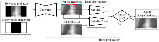
Figure 5.
Training workflow of the proposed out-painting network.
2.5. Quantitative Evaluation and Comparison
The out-painted projections were generated by applying the trained model to the test projections, and the image reconstruction was subsequently performed using the filtered back-projection algorithm with a Ram-Lak filter. The reconstructed s-IGDT image had a size of 150.48 × 150.48 × 168.96 cm3 with a 228 × 228 × 512 array. In order to assess the performance of the proposed out-painting method, we measured voxel value profile, signal-to-noise ratio (SNR), normalized root-mean-square error (NRMSE), peak SNR (PSNR), and structural similarity (SSIM) for the reconstructed s-IGDT images. The ROI for the SNR measurement was manually selected from a homogeneous area within the s-IGDT images. The NRMSE, PSNR, and SSIM were calculated as follows [25,26,27]:
where MAXO and MINO are the maximum and minimum voxel values of the out-painted s-IGDT image, respectively, and N is the number of voxels used for calculating the NRMSE. mR and mO are the mean voxel values of the reference and out-painted s-IGDT images, respectively, σj is the standard deviation of the corresponding image j, and σR, O is the covariance between the two images. The positive constants c1 and c2 were used to avoid a null denominator.
In the previous study, we reported the projection data correction (PDC) method for alleviating the truncation effects, which are caused by an s-IGDT system [3]. The PDC method can be simply implemented by using the geometric parameters of an imaging system, and the results showed that the PDC method outperformed the conventional method in reducing truncation effects. For comparison, the truncated projections were also restored by the PDC method, and the restored projections were reconstructed under the identical conditions used for acquiring the out-painted s-IGDT image.
3. Results
3.1. Lengths of the Source Array
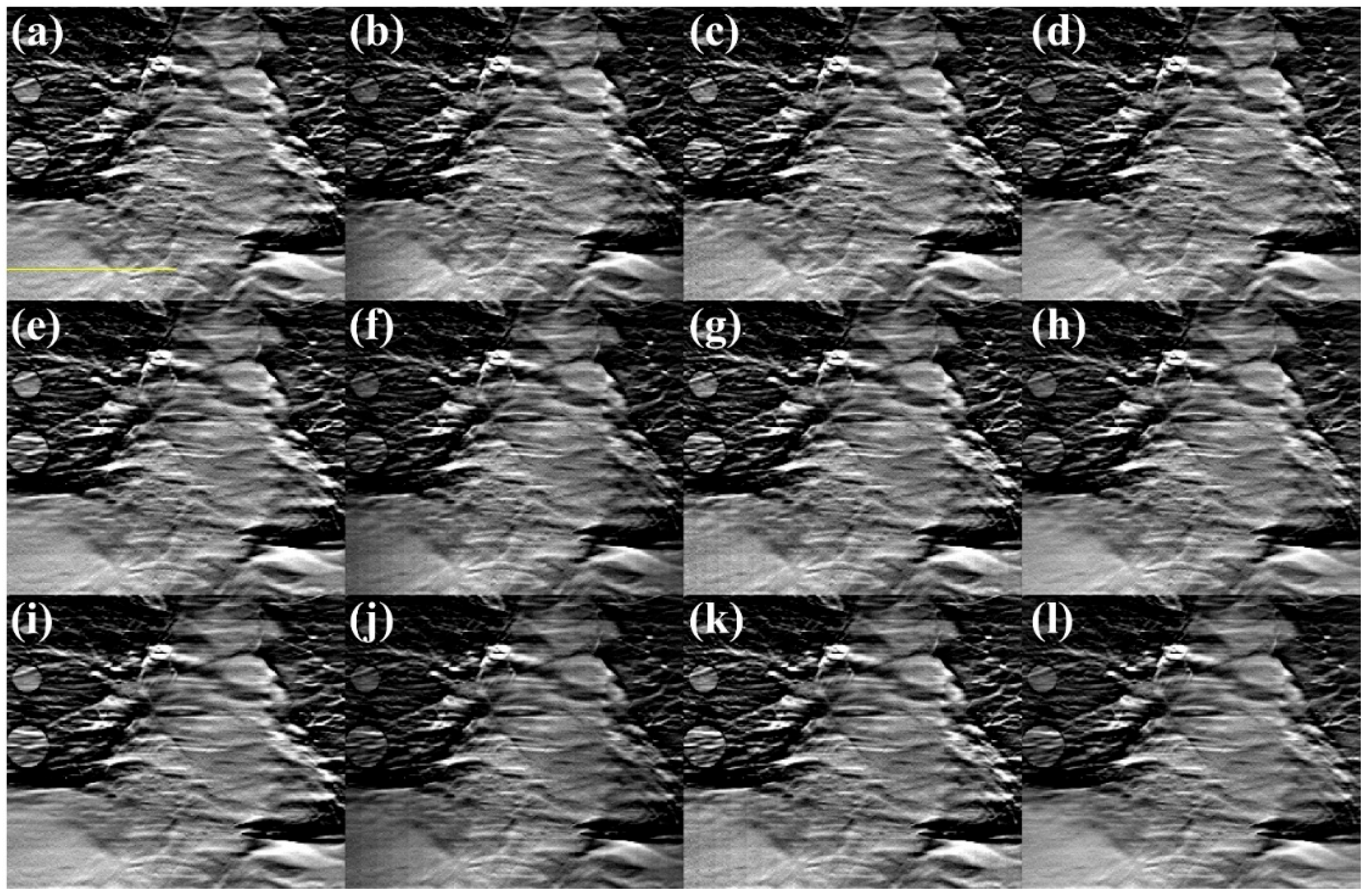
Figure 6 and Figure 7 show the s-IGDT images according to the lengths of the source array and the differential images between the reference and obtained s-IGDT images, respectively. In comparison to the reference images, the s-IGDT images reconstructed with the truncated projections exhibited noticeable step band-shaped artifacts, and the phenomenon was clearly identified through the differential images. The artifacts still remained in the s-IGDT images restored by the PDC method, whereas the proposed method significantly mitigated the artifacts for all the lengths of the source array.

Figure 6.
Reconstructed s-IGDT images with (a–d) 660, (e–h) 990, and (i–l) 1320 mm X-ray source arrays. The first to second columns represent the images reconstructed with the GT (reference) and truncated projections, respectively. The third to fourth columns correspond to the restored images using the PDC and proposed out-painting methods, respectively. The voxel value profiles were plotted along the yellow line.
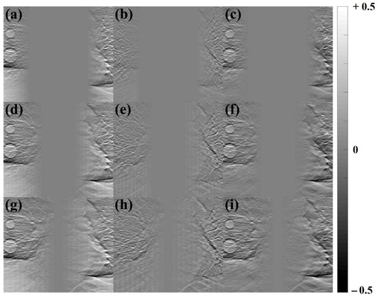
Figure 7.
Differential images between the reference images and the s-IGDT images. (a–c), (d–f) and (g–i) correspond to Figure 6b–d, f–h and j–l, respectively.
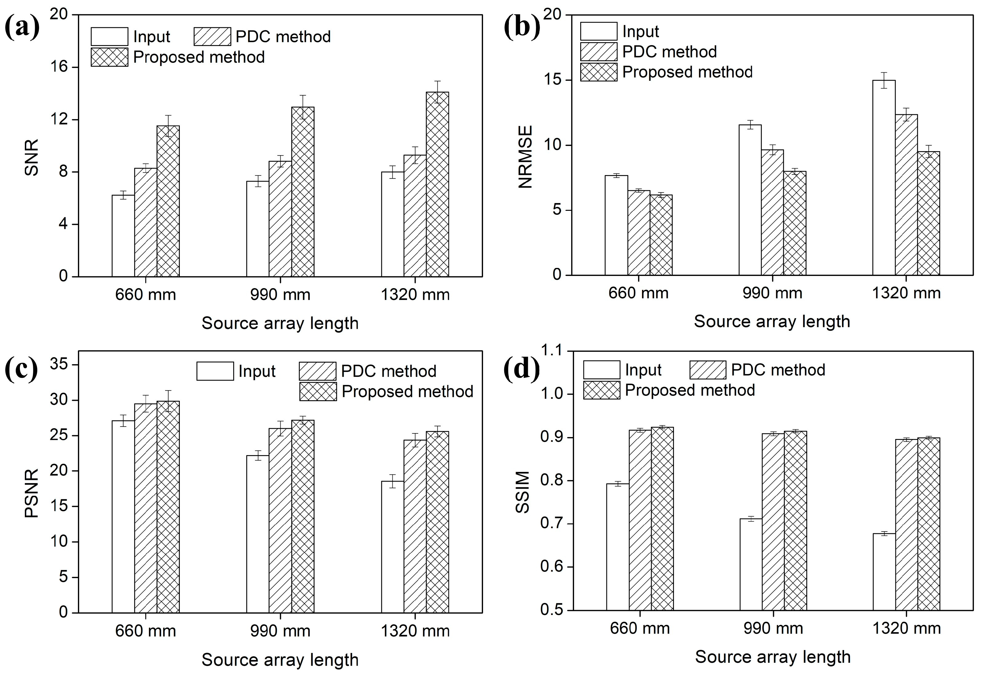
Figure 8 and Figure 9 present the voxel value profiles and the results of the quantitative analysis for the s-IGDT images obtained with the various lengths of the source array, respectively. As can be seen in Figure 8, the proposed out-painting method successfully restored the voxel values for truncated regions, and non-truncated regions in the s-IGDT image closely matched those in the reference image. The PDC and proposed methods increased the SNRs of the s-IGDT images obtained with the various lengths of the source array by an average of 23.35 and 79.62%, respectively. On average, the SNRs for the proposed method were 45.94% higher than those for the PDC method. In terms of the NRMSE, the proposed method outperformed both the conventional s-IGDT imaging and PDC methods, reducing the rates by 24.11–57.35 and 5.34–29.83%, respectively. Across all the lengths of the source array, the lowest NRMSEs were consistently observed with the proposed method. The PSNRs of the s-IGDT images were increased by both the PDC and proposed methods for all the lengths of the source array, and the increase ranges were 8.84–31.19 and 10.19–37.87% for the PDC and proposed methods, respectively. The proposed method yielded the maximum PSNRs of the s-IGDT images obtained with all the lengths of the source array, and the values were 1.24–5.10% higher than those for the PDC method. The s-IGDT images using the proposed method had higher SSIMs than those using the truncated projections and PDC method, with improvements ranging from 16.50 to 32.12 and 0.49–0.77%, respectively.
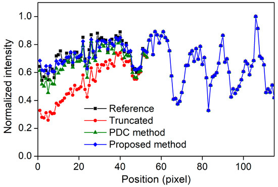
Figure 8.
Voxel value profiles of the s-IGDT images obtained with the 660 mm X-ray source array.

Figure 9.
(a) SNRs, (b) NRMSEs, (c) PSNRs, and (d) SSIMs with error bars of the s-IGDT images with the different lengths of the linear X-ray source array, respectively.
3.2. Numbers of the Focal Spots
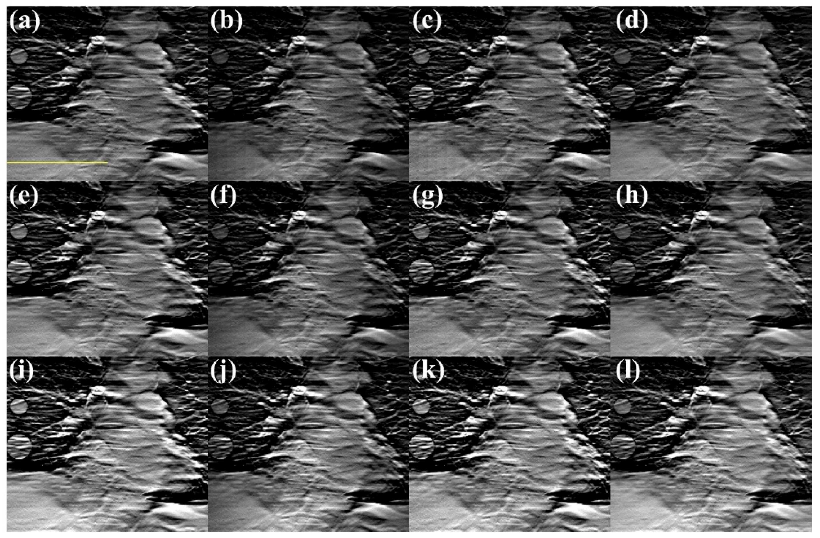
Figure 10 and Figure 11 show the s-IGDT images acquired by using various numbers of focal spots and the differential images between the reference and obtained s-IGDT images, respectively. Despite an increase in the focal spots, the truncation artifacts still remained in the s-IGDT image obtained with the truncated projections and 41 focal spots. Also, the voxel value discrepancies were observed in the truncated regions of the s-IGDT image acquired with the truncated projections and 81 focal spots. Similar to the results for the s-IGDT images with the various lengths of the source array, the proposed method substantially alleviated the truncation artifacts in comparison to the PDC method, regardless of the variation in the number of focal spots. The voxel value distortion for the truncated regions was also restored by the proposed out-painting method.

Figure 10.
Reconstructed s-IGDT images with (a–d) 21, (e–h) 41, and (i–l) 81 focal spots. The first to second columns represent the images reconstructed with the GT (reference) and truncated projections, respectively. The third to fourth columns correspond to the restored images using the PDC and proposed methods, respectively. The voxel value profiles were plotted along the yellow line.
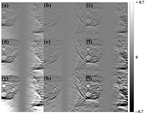
Figure 11.
Differential images between the reference images and the s-IGDT images. (a–c), (d–f) and (g–i) correspond to Figure 10b–d, f–h and j–l, respectively.
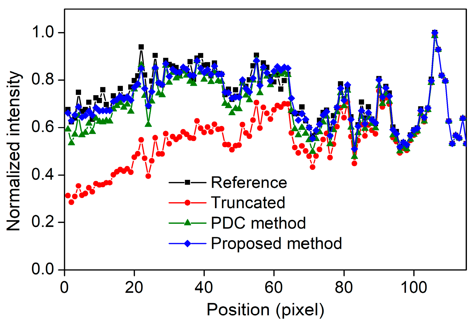
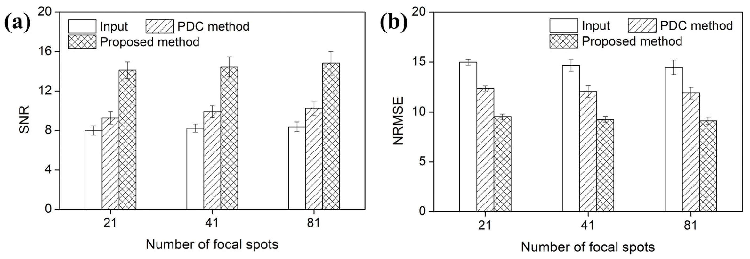
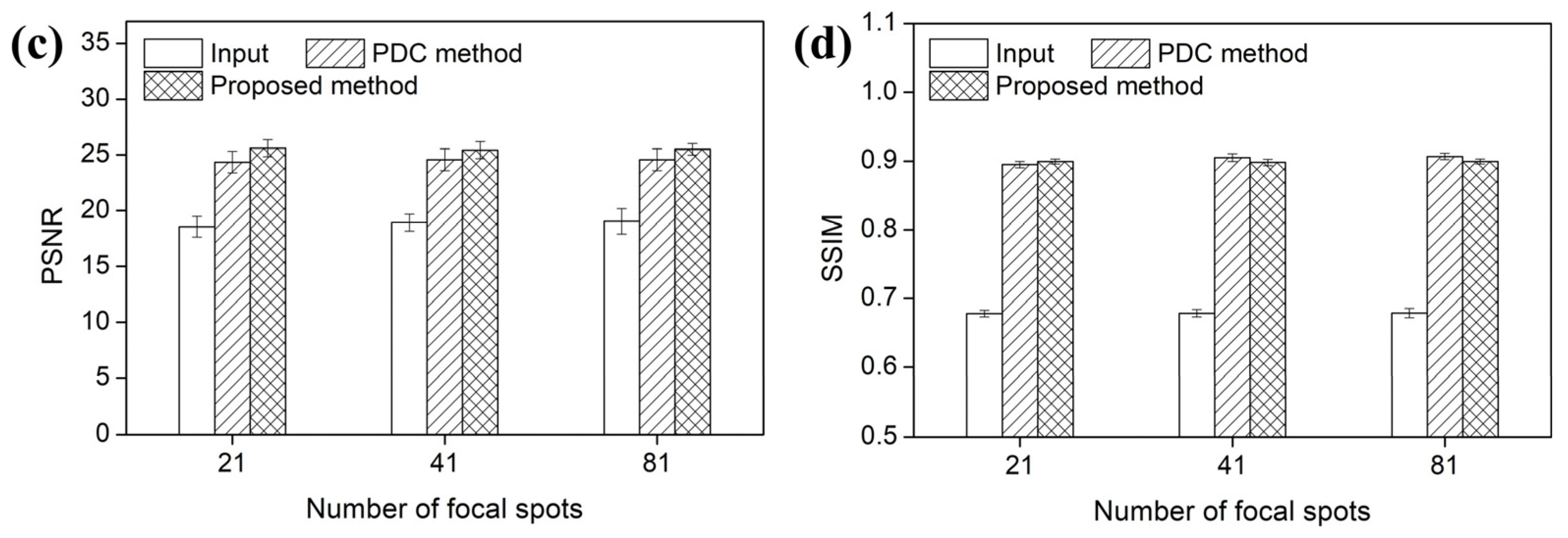
Figure 12 and Figure 13 present the voxel value profiles and the quantitative results for the s-IGDT images acquired with various numbers of focal spots, respectively. As observed in Figure 12, the proposed method restored the voxel values for the truncated and non-truncated regions in the s-IGDT image obtained with 81 focal spots. For the s-IGDT images obtained with various numbers of focal spots, the SNRs of the PDC and proposed methods were, on average, 19.62 and 76.25% higher than those of the s-IGDT images using the truncated projections, respectively. The degrees of the SNR improvements by the proposed method were 44.66–52.02% larger than those by the PDC method for the s-IGDT images obtained with various numbers of focal spots. Comparing the conventional s-IGDT imaging and PDC methods, the proposed method decreased the NRMSEs of the s-IGDT images by 57.35–58.60 and 29.83–30.23%, respectively. Across all the numbers of the focal spots, the lowest NRMSEs were consistently observed with the proposed method. The proposed method increased the PSNRs of the s-IGDT images obtained with various numbers of focal spots by an average of 35.37 and 4.16% compared to the truncated s-IGDT images and PDC method, respectively. For all the numbers of the focal spots, the proposed method consistently yielded higher SSIMs than the truncated s-IGDT images with an average increase of 32.28%. The SSIMs of the PDC method were slightly higher than those of the proposed method for the s-IGDT images obtained with 41 and 81 focal spots.
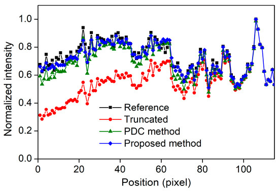
Figure 12.
Voxel value profiles of the s-IGDT images obtained with 81 focal spots.
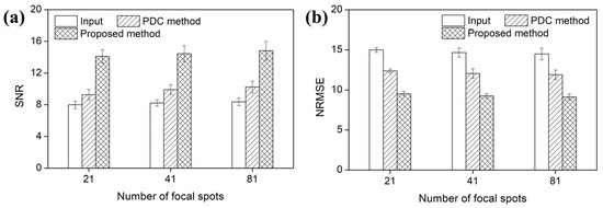
Figure 13.
(a) SNRs, (b) NRMSEs, (c) PSNRs, and (d) SSIMs of the s-IGDT images with the different numbers of focal spots, respectively.
4. Discussion
In this work, the DCGAN-based out-painting method was proposed for mitigating truncation artifacts in the s-IGDT images. The DCGAN architecture was modified by incorporating the dilated convolution block and dual-discriminator in order to enhance the accuracy of the out-painting task. The binary mask images were additionally employed as the input data of the generator for distinguishing between the truncated and non-truncated regions in a projection domain. The performance of the proposed out-painting method was compared to the PDC method in terms of visual observation, voxel value profiles, SNR, NRMSE, PSNR, and SSIM.
The truncation effects are influenced by the geometric configuration and scan parameters of the s-IGDT system, and the network training of this study was performed considering these properties. Thus, in this study, the training and test projections were prepared without the data augmentation techniques because the geometric configuration and scan parameters can be distorted in the augmented images. The purpose of this study was to preliminarily verify the feasibility of the proposed method for mitigating the truncation artifacts in the s-IGDT images. Thus, the hyperparameters for network training were manually selected without optimal tuning.
The results of visual assessment demonstrated that the proposed out-painting method was able to substantially mitigate truncation artifacts for the various s-IGDT system geometries, and its performance was superior to that of the PDC method. Also, the proposed out-painting method reduced the voxel value differences for the out-painted regions as well as preserved the image properties for the non-truncated regions. These findings represent that the proposed out-painting method can provide high-quality s-IGDT images without voxel value distortion, and the truncation artifact-free s-IGDT images can be acquired by using the proposed out-painting method regardless of system geometries. The SNRs of the s-IGDT images obtained by using the proposed out-painting method were 75.42–84.91 and 38.87–52.02% higher than those obtained with the truncated projections and PDC method, respectively. These enhancements describe that the proposed out-painting method is superior to the conventional s-IGDT imaging and PDC methods with respect to the noise characteristic of an output image and the pixel-wise similarity between the reference and output images, and this superiority is derived from the outstanding performance of the proposed method in mitigating the truncation artifacts. The proposed out-painting method achieved reductions in the NRMSEs ranging from 24.11 to 58.60 and 5.34–30.23% over the conventional s-IGDT imaging and PDC methods, respectively. The s-IGDT images obtained by using the proposed out-painting method had higher PSNRs than those obtained with the truncated projections and PDC method by 10.19–37.87 and 1.24–5.10%, respectively. Also, the SSIMs for the proposed out-painting method improved by 16.50–32.77% over those for the conventional s-IGDT imaging method. These results represent that the proposed out-painting method is able to enhance the quantitative accuracy of the s-IGDT image compared to the conventional s-IGDT imaging method. Eventually, we can conclude that the strategies for implementing the proposed out-painting method led to a successive reduction in the truncation artifacts in the s-IGDT image. Also, the improvements in the noise property and quantitative accuracy indicate that the proposed out-painting method has a significant potential for clinical applications requiring precise image interpretation and guidance. The encoder–decoder architecture used for the generator of the proposed network contributed to the generation of the out-painted images, harmonizing with the input images, and the critical features of the input images for out-painting were extracted and provided during network training by the dilated convolution block. Also, the dual-discriminator ensured the preservation of original textures for the non-truncated regions as well as the authenticity of generated images for the truncated regions. The generator of the proposed network was able to selectively learn the image generation task for the truncated regions by differentiating the truncated regions from the non-truncated regions using the binary mask images. These strategies comprehensively affected the performance of the proposed out-painting method.
With an increase in the number of focal spots, the SSIMs of the proposed out-painting method were slightly lower than those of the PDC method. This reduction was attributed to a loss of high-resolution information during network training, as can be seen in the out-painted regions of the differential images. Generally, the convolution layers in the GAN generator inherently downsample the features of an input image, and this process interrupts the effective transmission of fine-grained details to deeper layers [28,29]. Furthermore, the pixel-wise loss functions utilized in this study are limited to fully preserving the high-frequency components in an output image because the loss functions focus on reporting explicit pixel-level constraints rather than analyzing global similarities between input and output images [30]. Thus, the incomplete restoration of structural details induced a decrease in the SSIMs for the s-IGDT images acquired by the proposed out-painting method, and this phenomenon was more emphasized for the s-IGDT images with a large number of focal spots because the effect was accumulated by a reconstruction process. Several studies have reported that GAN-based networks, including residual blocks and skip connections, are able to improve the spatial resolution of output images [31,32]. And, the perceptual loss is utilized for restoring structural details in image transformation and enhancement tasks [33,34]. Accordingly, the further refinements of the network architecture with the residual block and skip connection are necessary in order to overcome the issue of spatial resolution degradation, and the perceptual loss function can be used to prevent the loss of high-level features.
Although the promising results demonstrated the performance of the proposed out-painting method in mitigating the truncation artifacts of the s-IGDT images, this study has several issues that should be addressed in future studies. We simulated the s-IGDT projections using the digital phantoms, which were constructed by using the clinical CT images acquired with the various tube voltages, tube currents, and slice thicknesses for different patients. And, a substantial portion of the obtained projections was allocated to the training images in order to enhance the trained model’s performance under the given dataset. This strategy led to a lack of test images, and consequently, the test images were prepared by using a single phantom. Thus, future studies should incorporate a broader and more diverse set of test images for generalizing the proposed method, and the cross-validation between the training and test images is necessary to ensure the robustness and statistical reliability of the performance evaluation. Several s-IGDT systems have been pre-clinically tested for practical applications, and the various scan strategies have been reported for optimizing their applications [4,5,35,36]. Thus, the proposed out-painting method needs to be implemented in accordance with the applications, and its performance should be experimentally investigated for enhancing the clinical applicability. Also, the effects of the residual block, skip connection, and perceptual loss function in the out-painting task would be evaluated in the near future.
5. Conclusions
This study proposed the DCGAN-based out-painting method for mitigating truncation artifacts in the s-IGDT images, and its performance was quantitatively evaluated by simulations. The results of this study revealed that truncation artifacts in the s-IGDT images can be suppressed by using the proposed method. The proposed method outperformed the conventional methods in terms of noise reduction. The quantitative accuracy for the proposed method was generally higher than that of the conventional methods, and the SSIMs of the proposed method were slightly lower than those of the PDC method for the s-IGDT images obtained with a large number of focal spots due to a loss of high-resolution information. In conclusion, the proposed out-painting method can offer a promising solution for enhancing the quality of the s-IGDT image. Also, we expect that the clinical availability of the s-IGDT could be ensured by the proposed out-painting method. The generalization of the proposed out-painting method would be possible with experimental validations.
Author Contributions
Conceptualization, B.K.; Formal analysis, B.K.; Visualization, B.K.; Writing—Original Draft Preparation, B.K. and S.L.; Investigation, S.L.; Methodology, S.L.; Supervision, S.L.; Writing—Review and Editing, S.L. All authors have read and agreed to the published version of the manuscript.
Funding
This paper was supported by the Konyang University Research Fund in 2024. And, this work was supported by the National Research Foundation of Korea (NRF) grant funded by the Korea government (MSIT) (No. RS-2023–00211810).
Institutional Review Board Statement
Not applicable.
Informed Consent Statement
Not applicable.
Data Availability Statement
The raw data supporting the conclusions of this article will be made available by the authors on request.
Conflicts of Interest
Author Burnyoung Kim was employed by the company Deepnoid Inc. The remaining authors declare that the research was conducted in the absence of any commercial or financial relationships that could be construed as potential conflicts of interest. The funders had no role in the design of the study; in the collection, analyses, or interpretation of data; in the writing of the manuscript; or in the decision to publish the results.
References
- Petropoulos, A.E.; Skiadopoulos, S.G.; Messaris, G.A.T.; Karahaliou, A.N.; Costaridou, L.I. Contrast and depth resolution of breast lessions in a digital breast tomosynthesis system. Phys. Med. 2016, 32, 277. [Google Scholar] [CrossRef]
- Chou, S.-H.S.; Kicska, G.A.; Pipavath, S.N.; Reddy, G.P. Digital Tomosynthesis of the Chest: Current and Emerging Applications. Radiographics 2014, 34, 359–372. [Google Scholar] [CrossRef]
- Kim, B.; Yim, D.; Lee, S. Development of a truncation artifact reduction method in stationary inverse-geometry X-ray laminography for non-destructive testing. Nucl. Eng. Technol. 2021, 53, 1626–1633. [Google Scholar] [CrossRef]
- Qian, X.; Rajaram, R.; Calderon-Colon, X.; Yang, G.; Phan, T.; Lalush, D.S.; Lu, J.; Zhou, O. Design and characterization of a spatially distributed multibeam field emission X-ray source for stationary digital breast tomosynthesis. Med. Phys. 2009, 36, 4389–4399. [Google Scholar] [CrossRef]
- Yang, G.; Rajarm, R.; Cao, G.; Sultana, S.; Liu, Z.; Lalush, D.; Lu, J.; Zhou, O. Stationary digital breast tomosynthesis system with a multi-beam field emission x-ray source array. In Proceedings of the SPIE Medical Imaging, San Diego, CA, USA, 16–21 February 2008; Volume 6913, pp. 441–450. [Google Scholar] [CrossRef]
- Kim, B.; Yim, D.; Lee, S. Reduction of truncation artifact in stationary inverse-geometry digital tomosynthesis using convolutional neural network. In Proceedings of the SPIE Medical Imaging, Houston, TX, USA, 15–20 February 2020; Volume 11312, pp. 1111–1116. [Google Scholar] [CrossRef]
- Thapa, D.; Billingsley, A.; Luo, Y.; Inscoe, C.; Zhou, O.; Lu, J.; Lee, Y. Orthogonal tomosynthesis for whole body skeletal imaging enabled by carbon nanotube x-ray source array. In Proceedings of the SPIE Medical Imaging, San Diego, CA, USA, 20 February–28 March 2022; Volume 12031, pp. 1018–1024. [Google Scholar] [CrossRef]
- Lopez Montes, A.; McSkimming, T.; Zbijewski, W.; Siewerdsen, J.H.; Delnooz, C.; Skeats, A.; Gonzales, B.; Sisniega, A. Stationary X-ray tomography for hemorrhagic stroke imaging: Sampling and resolution properties. In Proceedings of the 7th International Conference on Image Formation in X-ray Computed Tomography, Baltimore, MD, USA, 12–16 June 2022; Volume 12304, pp. 151–157. [Google Scholar] [CrossRef]
- Brock, A.; Donahue, J.; Simonyan, K. Large Scale GAN Training for High Fidelity Natural Image Synthesis. arXiv 2019, arXiv:1809.11096. [Google Scholar]
- Bergmann, U.; Jetchev, N.; Vollgraf, R. Learning Texture Manifolds with the Periodic Spatial GAN. arXiv 2017, arXiv:1705.06566. [Google Scholar]
- Yu, J.; Lin, Z.; Yang, J.; Shen, X.; Lu, X.; Huang, T.S. Generative image inpainting with contextual attention. In Proceedings of the IEEE Conference on Computer Vision and Pattern Recognition, Salt Lake City, UT, USA, 18–22 June 2018; Volume 2018, pp. 5505–5514. [Google Scholar] [CrossRef]
- Gomi, T.; Sakai, R.; Hara, H.; Watanabe, Y.; Mizukami, S. Usefulness of a Metal Artifact Reduction Algorithm in Digital Tomosynthesis Using a Combination of Hybrid Generative Adversarial Networks. Diagnostics 2021, 11, 1629. [Google Scholar] [CrossRef]
- Gomi, T.; Kijima, Y.; Kobayashi, T.; Koibuchi, Y. Evaluation of a Generative Adversarial Network to Improve Image Quality and Reduce Radiation-Dose during Digital Breast Tomosynthesis. Diagnostics 2022, 12, 495. [Google Scholar] [CrossRef]
- Nazeri, K.; Ng, E.; Joseph, T.; Qureshi, F.Z.; Ebrahimi, M. EdgeConnect: Generative Image Inpainting with Adversarial Edge Learning. arXiv 2019, arXiv:1901.00212. [Google Scholar]
- Podgorsak, A.R.; Bhurwani, M.M.S.; Ionita, C.N. CT artifact correction for sparse and truncated projection data using generative adversarial networks. Med. Phys. 2021, 48, 615–626. [Google Scholar] [CrossRef]
- Armato, S.G., III; Hadjiiski, L.M.; Tourassi, G.D.; Drukker, K.; Giger, M.L.; Li, F.; Redmond, G.; Farahani, K.; Kirby, J.S.; Clarke, L.P. LUNGx Challenge for computerized lung nodule classification: Reflections and lessons learned. J. Med. Imaging 2015, 2, 020103. [Google Scholar] [CrossRef]
- Zeng, G.L.; Gullberg, G.T. Unmatched projector/backprojector pairs in an iterative reconstruction algorithm. IEEE Trans. Med. Imaging 2000, 19, 548–555. [Google Scholar] [CrossRef] [PubMed]
- Radford, A.; Metz, L.; Chintala, S. Unsupervised Representation Learning with Deep Convolutional Generative Adversarial Networks. arXiv 2016, arXiv:1511.06434. [Google Scholar]
- Chen, X.; Duan, Y.; Houthooft, R.; Schulman, J.; Sutskever, I.; Abbeel, P. InfoGAN: Interpretable Representation Learning by Information Maximizing Generative Adversarial Nets. Adv. Neural. Inf. Process. Syst. 2016, 29, 2180–2188. [Google Scholar]
- Mirza, M.; Osindero, S. Conditional Generative Adversarial Nets. arXiv 2014, arXiv:1411.1784. [Google Scholar]
- Arjovsky, M.; Chintala, S.; Bottou, L. Wasserstein generative adversarial networks. In Proceedings of the International Conference on Machine Learning, Sydney, Australia, 6–11 August 2017; Volume 70, pp. 214–223. [Google Scholar]
- Yu, F.; Koltun, V. Multi-Scale Context Aggregation by Dilated Convolutions. arXiv 2016, arXiv:1511.07122. [Google Scholar]
- Lucic, M.; Kurach, K.; Michalski, M.; Gelly, S.; Bousquet, O. Are gans created equal? a large-scale study. Adv. Neural. Inf. Process. Syst. 2018, 31, 698–707. [Google Scholar]
- Zhang, Z.; Deng, C.; Shen, Y.; Williamson, D.S.; Sha, Y.; Zhang, Y.; Song, H.; Li, X. On Loss Functions and Recurrency Training for GAN-based Speech Enhancement Systems. arXiv 2020, arXiv:2007.14974. [Google Scholar]
- Wang, Z.; Bovik, A.C.; Sheikh, H.R.; Simonceli, E.P. Image quality assessment: From error visibility to structural similarity. IEEE Trans. Image Process. 2004, 13, 600–612. [Google Scholar] [CrossRef] [PubMed]
- Hore, A.; Ziou, D. Image quality metrics: PSNR versus SSIM. In Proceedings of the International Conference on Pattern Recognition, Istanbul, Turkey, 23–26 August 2010; pp. 2366–2369. [Google Scholar]
- Park, J.; Hwang, D.; Kim, K.Y.; Kang, S.K.; Kim, Y.K.; Lee, J.S. Computed tomography super-resolution using deep convolutional neural network. Phys. Med. Biol. 2018, 63, 145011. [Google Scholar] [CrossRef]
- Pathak, D.; Krahenbuhl, P.; Donahue, J.; Darrell, T.; Efros, A.A. Context encoders: Feature learning by inpainting. In Proceedings of the IEEE Conference on Computer Vision and Pattern Recognition, Las Vegas, NV, USA, 26 June–1 July 2016; Volume 2016, pp. 2536–2544. [Google Scholar]
- Sun, H.; Fan, R.; Li, C.; Lu, Z.; Xie, K.; Ni, X.; Yang, J. Imaging study of pseudo-CT synthesized from cone-beam CT based on 3D CycleGAN in radiotherapy. Front. Oncol. 2021, 11, 603844. [Google Scholar] [CrossRef]
- Li, J.; Liang, X.; Wei, Y.; Xu, T.; Feng, J.; Yan, S. Perceptual generative adversarial networks for small object detection. In Proceedings of the IEEE Conference on Computer Vision and Pattern Recognition, Honolulu, HI, USA, 21–26 July 2017; Volume 2017, pp. 1222–1230. [Google Scholar] [CrossRef]
- Zhang, X.; Feng, C.; Wang, A.; Yang, L.; Hao, Y. CT super-resolution using multiple dense residual block based GAN. Signal Image Video Process. 2021, 15, 725–733. [Google Scholar] [CrossRef]
- Bulat, A.; Yang, J.; Tzimiropoulos, G. To learn image super-resolution, use a GAN to learn how to do image degradation first. In Proceedings of the European Conference on Computer Vision, Munich, Germany, 8–14 September 2018; pp. 185–200. [Google Scholar]
- Johnson, J.; Alahi, A.; Fei-Fei, L. Perceptual losses for real-time style transfer and super-resolution. In Proceedings of the Computer Vision-ECCV 2016 Part II, Amsterdam, The Netherlands, 11–14 October 2016; Volume 14, pp. 694–711. [Google Scholar] [CrossRef]
- Gholizadeh-Ansari, M.; Alirezaie, J.; Babyn, P. Deep Learning for Low-Dose CT Denoising Using Perceptual Loss and Edge Detection Layer. J. Digit. Imaging 2020, 33, 504–515. [Google Scholar] [CrossRef] [PubMed]
- Primidis, T.G.; Wells, S.G.; Soloviev, V.Y.; Welsch, C.P. 3D chest tomosynthesis using a stationary flat panel source array and a stationary detector: A Monte Carlo proof of concept. Biomed. Phys. Eng. Express 2022, 8, 015006. [Google Scholar] [CrossRef]
- Billingsley, A.; Inscoe, C.; Lu, J.; Zhou, O.; Lee, Y.Z. Second generation stationary chest tomosynthesis with faster scan time and wider angular span. Med. Phys. 2024, 52, 542–552. [Google Scholar] [CrossRef]


Disclaimer/Publisher’s Note: The statements, opinions and data contained in all publications are solely those of the individual author(s) and contributor(s) and not of MDPI and/or the editor(s). MDPI and/or the editor(s) disclaim responsibility for any injury to people or property resulting from any ideas, methods, instructions or products referred to in the content. |
© 2025 by the authors. Licensee MDPI, Basel, Switzerland. This article is an open access article distributed under the terms and conditions of the Creative Commons Attribution (CC BY) license (https://creativecommons.org/licenses/by/4.0/).