Abstract
To improve the reliability of glass-fiber/epoxy-reinforced polymer (GFRP) composites, four laminates were manufactured by vacuum bagging: (i) a virgin baseline, (ii) an epoxy system modified with 15 wt% high-density polyethylene (PE) powder, (iii) a laminate interleaved with electrospun polyacrylonitrile (PAN)-based nanofiber mats, and (iv) a hybrid combining both modifiers. The specimens were subjected to low-velocity impacts; half were then heated at 150 °C for 30 min and re-impacted. PE caused peak-load loss up to 30% compared to virgin specimens but recovered 25% after heating by filling cracks. PAN interleaves limited the loss to 5%, and the hybrid laminate merged the benefits: it showed the highest first-impact load, retained 96% on re-impact, and gained a further 10% after heating while keeping the smallest permanent indentation. SEM confirmed molten PE migrating along the nanofiber mat to repair delamination fronts, explaining the laminate’s bell-shaped, oscillation-free force response and demonstrating a practical, synergistic self-healing mechanism. Collectively, the results demonstrate a clear structure–property connection: PAN nanofibers capture crack growth, while PE provides temperature-triggered self-healing, and their synergy offers a practical pathway to lightweight GFRP structures with enhanced impact resilience and restoration of mechanical integrity.
1. Introduction
Glass-fiber-reinforced polymers (GFRPs) are among the most widely utilized composite materials owing to their favorable properties, including a high strength-to-weight ratio, corrosion resistance, and ease of processing and cost efficiency. These characteristics make GFRPs suitable for a wide range of applications in industries such as aerospace, automotive, marine, and construction. However, despite these benefits, GFRP composites remain prone to impact-induced damage mechanisms that compromise structural integrity. During manufacturing, microstructural defects such as voids, fiber misalignment, and poor fiber–matrix interfacial bonding may occur, which can significantly compromise the mechanical performance of the composite. One of the most critical issues associated with these defects is delamination, defined as the separation of composite layers under stress. Delamination can occur not only due to inherent defects but also as a result of out-of-plane impact events [1], and it substantially reduces the material’s load-bearing capacity while accelerating long-term degradation [2]. Consequently, GFRP composites often exhibit limited impact tolerance; even relatively low-energy impacts can introduce internal damage that may not be immediately visible but can propagate under cyclic or sustained loading conditions. This hidden damage may ultimately lead to catastrophic failure, thereby reducing the operational lifespan of the component or rendering it entirely unserviceable. Indeed, several studies have shown that low-velocity impacts can initiate internal fracture mechanisms in composite materials, including matrix cracking and fiber–matrix debonding [3,4]. These damage modes frequently remain undetectable in early stages yet continue to grow over time, compromising the reliability and long-term performance of GFRP structures. Consequently, enhancing damage tolerance and integrating smart functionalities into composite materials represent major areas of ongoing research in advanced composite technology, among which self-healing has emerged as a particularly promising approach [5].
Self-healing methods in polymeric systems are generally categorized as either intrinsic or extrinsic [6], each employing different strategies to trigger the self-healing mechanism. Intrinsic self-healing approaches typically rely on reversible covalent bonding or reversible intermolecular interactions [7], among other methods. In contrast, extrinsic methods utilize embedded microcapsules, thermoplastic particles, vascular networks, or hollow fibers as healing reservoirs [8]. Upon damage, these healing agents are released into the crack zone through external stimuli, leading to autonomous repair of the material. Interrupted fatigue tests on fiber-reinforced epoxy composites containing thermoplastics have demonstrated that early-stage damage recovery can significantly extend fatigue life [9,10,11,12,13].
For example, Chuves et al. [14] conducted a study to evaluate the effect of self-healing agent content on the mechanical behavior of composite laminates. Their ANOVA analysis revealed that the fraction of healing agent had a more significant impact on the mechanical properties than the internal dispersion within the same laminate prior to the healing cycle. The results indicated a linear reduction in shear stress with increasing poly(ethylene-co-methacrylic acid) content, which was attributed to the decreased stiffness caused by the ductile nature of the thermoplastic. The healing mechanism was found to be ineffective for translaminar and intra-laminar damage due to the predominant localization of healing particles within the interlaminar regions. Nevertheless, the healing efficiency achieved an average of 62% in terms of shear strength recovery and 106% for toughness, primarily through the closure of shear cracks. This corresponded to a reduction of up to 57% in the damaged area relative to the initial crack dimensions.
Recent studies have focused on enhancing both the mechanical properties and functional performance of fiber-reinforced polymer composites through the incorporation of various thermoplastic fillers and nanostructures. Ethylene-based thermoplastics such as polyethylene (PE), poly(ethylene-co-methacrylic acid) (EMAA), poly(ethylene glycol) methyl ether methacrylate (PEGMA), and ethylene-vinyl acetate (EVA) have been employed to improve toughness and energy dissipation [9,15,16,17,18]. In addition, other thermoplastics such as polyvinyl butyral (PVB) [16], poly(bisphenol A-co-epichlorohydrin) (PBAE) [19,20], and polycaprolactone (PCL) [21] have also been explored. Furthermore, several studies have investigated the incorporation of nanostructured materials in various morphologies to further improve performance characteristics [22,23].
Upon localized thermal activation, the thermoplastic phase can soften and flow into crack regions, thereby enabling autonomous or externally triggered healing of microcracks. This mechanism has been shown to enhance damage tolerance and extend the fatigue life of fiber-reinforced composites [23]. Several studies have reported that the incorporation of a moderate amount of thermoplastic healing agent, typically around 15 wt%, can yield significant improvements in healing efficiency [14,17,24,25]. Furthermore, post-impact thermal treatment, such as heating at 150 °C for 30 min, has been demonstrated to facilitate thermoplastic flow into interlaminar cracks following low-velocity impacts, thereby improving delamination resistance [15,16,26,27,28,29].
Certain thermoplastic particles contribute to the healing process through a pressure-driven delivery mechanism [30], in which trapped moisture within the composite transforms into vapor during heat treatment. This vapor pressure facilitates the flow of molten thermoplastic into microcracks, thereby activating the self-healing mechanism. Once molten, the thermoplastic disperses and fills the damaged regions, assisting in the restoration of structural integrity [31]. Upon cooling and solidification, the vapor dissipates, and small voids may remain within the re-solidified thermoplastic phase. These residual cavities are typically minor and do not compromise mechanical performance significantly. On the contrary, the re-bonding of fracture surfaces enhances stress distribution under subsequent loading, thereby improving damage tolerance and prolonging the service life of the composite. For non-reactive thermoplastics such as EVA, the healing mechanism primarily relies on their intrinsic viscosity and surface adhesion capabilities, which enable the molten material to adhere to fracture surfaces and facilitate crack closure without relying on chemical reaction [15].
Although the incorporation of thermoplastics into polymer matrices offers several advantages, it is not without limitations. The inclusion of thermoplastic particles can lead to a reduction in tensile strength [32] and may also increase initial production costs as well as processing time. However, in scenarios where composite components are susceptible to damage and rapid repair is critical, the development of self-healing materials that can restore functionality without requiring replacement presents a highly advantageous solution [4,18]. The industrial implementation of such self-healing strategies is gaining significant interest, particularly in sectors such as aerospace, automotive, and other fields where durability, renewability, and extended service life are of paramount importance [5].
Enhancements in composite performance are not limited to matrix modification, as the interleaving of nanofiber mats within composite laminates has also been widely explored [33,34,35]. Electrospinning is considered one of the most frequently employed techniques for generating nanofiber mats in recent years [33,34,35], and the integration of polyacrylonitrile (PAN)-based electrospun nanofiber mats interlayered into the fiber-reinforced polymer composites has shown significant potential in improving interlaminar fracture toughness and energy absorption capacity, owing to PAN’s high carbon content, excellent mechanical properties, and thermal stability up to 300 °C [36,37,38]. PAN-based nanofiber mats are typically produced using the electrospinning technique, which involves the ejection of a polymer solution under a high-voltage electric field toward a conductive collector [39,40].
The resulting nanofibers exhibit exceptional surface area and porosity, which make them highly suitable for a wide range of engineering applications due to their large specific surface area [41] and strong mechanical interlocking capability, functioning as nanoscale bridging elements that hinder crack propagation and thereby improve the overall toughness and mechanical performance of the laminate [38,42,43,44,45,46,47].
The synergistic integration of self-healing thermoplastics and mechanically reinforcing nanofibers offers a promising approach for the development of next-generation glass-fiber-reinforced polymer (GFRP) composites with enhanced damage tolerance and extended service life. The aforementioned studies demonstrate that both thermoplastic modifiers such as high-density polyethylene and PAN-based nanofiber mats, when used independently, can significantly improve the mechanical performance of laminated composites. However, the simultaneous incorporation of these two functional components may further augment the structural integrity and multifunctional capabilities of the composite system.
Therefore, in this study, both PE powder as self-healing material and PAN nanofiber mats were electrospun and then interleaved into glass fiber/epoxy to manufacture self-healing nanofiber-modified GFRP composite structures. Low-velocity impact tests conducted on the specimens. Comparisons were made to investigate the effects of the modifications on impact resistance, energy absorption, and tensile strength capabilities of the specimens.
2. Materials and Methods
Electrospinning was employed for the fabrication of the nanofiber mats. The polyacrylonitrile (PAN) solution was prepared by dissolving PAN powder in dimethylformamide (DMF), with both the polymer and the solvent procured from Sigma-Aldrich. The PAN polymer is characterized by the chemical formula (C3H3N)n, a molecular weight of 1.5 × 10⁵ g/mol, a glass transition temperature of 85 °C, a melting point of 317 °C, and a density of 1.184 g/mL at 25 °C.
Then, PAN powder was dissolved in DMF at a concentration of 12% w/w [39] in a screw-capped glass bottle and left to rest for 48 h under ambient conditions to ensure complete solvation. The resulting solution was subsequently treated in an ultrasonic bath for 8 h at room temperature to enhance homogeneity and dispersion. Finally, the homogeneous solution was loaded into a 10 mL syringe and mounted onto a syringe pump system for electrospinning. Parameters such as solution viscosity, electric field strength, needle-to-collector distance, and ambient humidity play a critical role in determining the diameter and morphology of the resulting fibers. Accordingly, the electrospinning process was conducted under the following conditions: an applied voltage of 20 kV, a tip-to-collector distance of 150 mm, a solution feed rate of 1 mL/h, and a rotating drum collector with a circumference of 220 mm and a length of 130 mm, operated at 70 rpm. The ambient temperature was maintained at 25 °C with a relative humidity of approximately 50%. The process was continued until the entire polymer solution had been consumed.
Following electrospinning, the nanofiber mats were dried at room temperature under continuous dehumidification for 72 h to ensure the complete evaporation of residual solvents. Subsequently, they were stored in sealed plastic containers for later use. The electrospun mats exhibited an average thickness of 2.98 ± 0.3 μm, and the surface density was calculated as 50.8 ± 0.22 g/m2 by dividing the total weight of the nanofiber mat (Figure 1a) by its surface area.
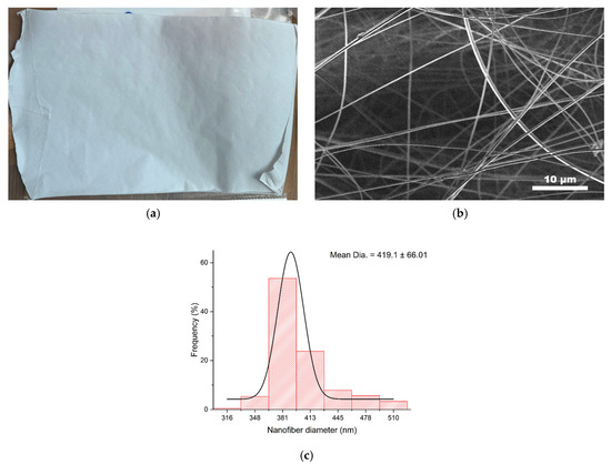
Figure 1.
(a) Nanofiber mat, (b) SEM image of the nanofibers, and (c) frequency of the diameter size.
The morphological characteristics and surface quality of the fibers were analyzed using scanning electron microscopy (SEM) (Figure 1b). SEM imaging was performed using a Thermo Fisher Scientific Apreo S LoVac device. Specimens were placed in a clean vacuum chamber to prevent dust interference and minimize particulate contamination. As no surface coating or conductive preparation was deemed necessary, the samples were imaged in their original state. Multiple regions of the mats were examined at various magnifications to ensure image clarity and consistency, and the highest-quality micrographs were selected for analysis.
The SEM results confirmed that the electrospun nanofibers were suitable for use in composite fabrication. Fiber diameters were measured using ImageJ software v1.51 equipped with the DiameterJ plugin v1.018 [48], revealing an average diameter of 419.1 ± 66.01 nm (Figure 1c). Although some variability in fiber diameter and continuity were observed, the overall distribution remained within acceptable limits, and given that the standard deviation was less than 0.5, a Gaussian distribution [49] was also calculated for statistical analysis, which confirms a valid distribution.
The polyethylene (PE) used in this study was supplied in powder form by Arya Sasol Polymer Company, with an average particle size of 200 µm. The material exhibits a high density of 0.95 g/cm3 (at 23 °C), a melt flow index (MFI) of 10 dg/min (190 °C/12.6 kg), a Young’s modulus of 1050 MPa, a tensile strength of 55 MPa, a tensile stress at yield of 26 MPa, and a melting point of 132 °C.
A commercial epoxy resin system (MGS L160/H160) was employed as the matrix and mixed with its corresponding curing agent at a weight ratio of 100:25, in accordance with the manufacturer’s instructions (Figure 2a). For all specimen groups, eight layers of dry E-glass fiber fabric with a [0°/90°] bidirectional orientation were used as the reinforcement [50]. The fabrics were supplied by a commercial distributor (Kompozit.net, Istanbul, Türkiye) and featured a plain weave architecture with a surface density of 200 g/m2 and a thickness of 0.2 mm. Additional properties of the E-glass fibers include a tensile strength of 2 GPa, a Young’s modulus of 80 GPa, a shear modulus of 30 GPa, a density of 2520 kg/m3, a glass transition temperature of 350 °C, a thermal conductivity of 1.2 W/m·K, and a coefficient of thermal expansion of 4.8 × 10⁻⁶ K−1.
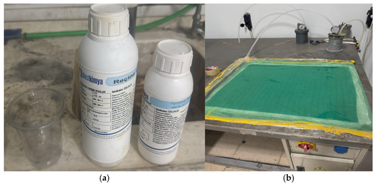
Figure 2.
(a) Epoxy set; (b) vacuum bag method.
In this study, four distinct groups of composite specimens were prepared: (i) virgin specimens, (ii) PE-modified specimens, (iii) nanofiber-reinforced specimens, and (iv) hybrid specimens incorporating both PE and PAN nanofiber mats. The virgin specimens consisted solely of neat epoxy reinforced with eight layers of E-glass fabric. The nanofiber-reinforced specimens were composed of neat epoxy and an eight-layer E-glass laminate, in which a PAN-based electrospun nanofiber mat was interleaved precisely at the mid-plane between the 4th and 5th layers. The PE-modified specimens comprised eight layers of E-glass fabric infused with an epoxy matrix containing 15 wt% dispersed PE powder. Finally, the hybrid specimens included eight layers of E-glass reinforcement infused with an epoxy system containing 15 wt% PE powder, along with a PAN nanofiber mat interleaved at the same mid-plane position.
All composite laminates were fabricated using the vacuum bagging technique, in which the glass fiber fabrics were manually impregnated with the epoxy mixture and then stacked layer by layer into a mold (Figure 2b). To ensure a uniform distribution of PE powder within the epoxy system, the PE-modified epoxy was prepared by mechanically stirring the powder with the resin for one hour, followed by the addition of the curing agent, which was mixed for an additional 15 min. The resulting mixture was then applied to the fabric layers. The assembled layup was sealed in a vacuum bag, and vacuum was applied using a pump to remove entrapped air and to promote uniform resin flow and compaction. Special attention was given to maintaining vacuum integrity and preventing air leakage throughout the curing process. The fabrication was carried out at room temperature and approximately 50% relative humidity. After manufacturing, the specimens were removed from the vacuum bag and subsequently stored under ambient conditions for an additional 24 h to ensure complete curing.
For each configuration, six nominally identical specimens were fabricated, resulting in a total of twenty-four specimens. To minimize variability between samples, each group was manufactured as a single composite plate with nominal dimensions of 760 × 380 × 4 mm3 (including error margins). These plates were subsequently machined into standardized specimens with dimensions of 150 × 100 × 4 mm3, in accordance with ASTM D7136 [51], to ensure high dimensional accuracy for low-velocity impact testing. Special care was taken to ensure that the nanofiber-interleaved composite specimens contained a continuous nanofiber mat extending uniformly across the entire width and length of the sample.
Low-velocity impact tests were performed in accordance with the ASTM D7136 standard using a custom-designed drop-weight impact tower equipped with a hemispherical impactor head of 12 mm diameter and a total mass of 5.6 kg. The specimens were centrally mounted in a rigid steel rectangular fixture and secured with four mechanical clamps to prevent movement during testing. The impactor was released from a height sufficient to achieve an initial velocity of 2 m/s, corresponding to an impact energy of 11 J.
The custom-built impact device (Figure 3) was integrated with a high-sensitivity force sensor operating in the millivolt range to capture force signals during the impact event. These signals were amplified, filtered, and transmitted to a data acquisition (DAQ) card (National Instruments), and subsequently recorded using NI SignalExpress software 2015 at a sampling frequency of 25 kHz.
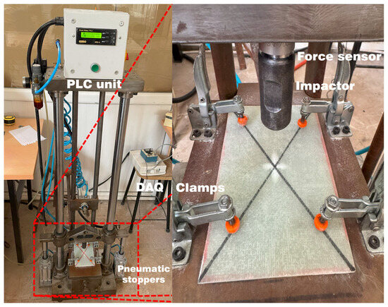
Figure 3.
Low-velocity impact device with a specimen.
As outlined in the ASTM D7136 standard, Newton’s second law of motion was applied to derive the kinematic response of the impactor over time. Velocity was obtained by integrating the acceleration with respect to time, and displacement was subsequently derived through a second integration of the velocity data. To ensure that only a single impact was recorded per test, an anti-rebound mechanism was also incorporated into the setup to prevent multiple impacts.
Energy losses due to internal damping within the sensor and frictional resistance in the system components were considered negligible. Therefore, the total impact energy was approximated as the sum of the energy absorbed by the specimen and the rebound energy of the impactor. The absorbed energy was primarily attributed to plastic deformation and fracture mechanisms occurring within the laminate structure.
All twenty-four specimens were subjected to an initial low-velocity impact test, conducted in accordance with ASTM D7136. Subsequently, half of the specimens, three from each of the four groups, were thermally conditioned in a circulating-air oven at 150 °C for 30 min. After cooling to ambient temperature, each specimen underwent a second low-velocity impact using the same setup as in the initial test.
This procedure allowed for a comparative assessment between two test conditions: (i) specimens subjected to two consecutive impacts without any thermal treatment, and (ii) specimens exposed to a second impact following post-impact heat treatment after the initial impact, enabling the evaluation of the self-healing effect induced by thermal activation.
3. Results
The experimental findings are presented in the form of comparative graphs. To facilitate interpretation, each line in the graphs is labeled as follows: the label “1” denotes the first impact on the representative specimens from the untreated groups, while “1U” corresponds to the second impact on the same specimens without any thermal intervention. The label “2” represents the first impact on the yet-thermallytreated specimens, and “2T” indicates the response of those specimens after heat treatment and subsequent re-impact. Accordingly, each graph includes four traces per material type; for example, V1, V1U, V2, and V2T represent virgin composites, with analogous notations (N, P, H) corresponding to nanofiber-interleaved, PE-modified, and hybrid composite groups, respectively. Table 1 summarizes the specimen labeling scheme used in the graphs to enhance clarity and ensure consistency.

Table 1.
Specimen groups according to treatment conditions and impact tests.
Impactor displacement, energy, and velocity were calculated from the raw data based on Newton’s second law of motion, with appropriate corrections applied to minimize measurement errors. Subsequently, force-time, energy-time, and energy-displacement curves were generated and analyzed to evaluate the impact response.
3.1. Force-Time
Examination of the force-time traces of the specimens revealed a more nuanced hierarchy of stiffness, damage tolerance and thermal recovery across the four laminate composite architectures.
The untreated specimen (Figure 4a) exhibited a smooth rise to approximately 1950 N (± 150 N) followed by a ragged plateau and a secondary hump, features that are typical of brittle matrix cracking and a subsequent delamination. Upon re-impact (V1U), the peak force was reduced by ~25% to approximately 1450 N (± 190 N) and advanced catastrophic unloading, confirming substantial stiffness loss. Thermal conditioning (V2T) did not restore the peak; instead, it delayed force build-up, confirming that heat only relaxed residual stresses without healing the damage network. Virgin fiber/epoxy laminates demonstrated significant mechanical deterioration under repeated impacts and thermal cycling. The observed drop in force for V1U and V2T suggested matrix embrittlement, likely due to interfacial degradation and thermal effect.
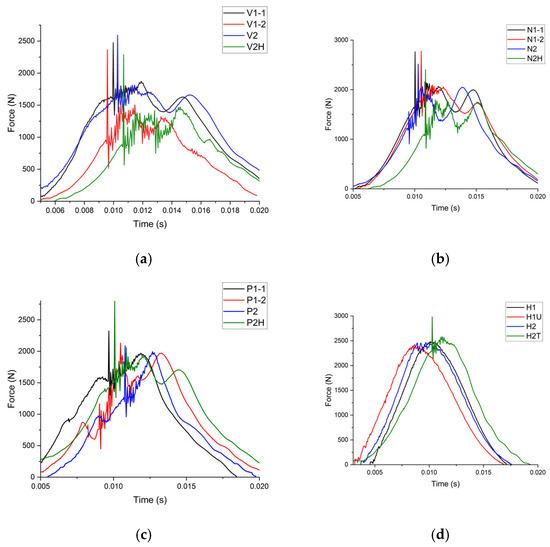
Figure 4.
Force-time graphs of (a) virgin (b) nanofiber-layered, (c) PE-modified, and (d) hybrid specimens.
All untreated and re-impacted lines (Figure 4b) clustered tightly, peaking at approximately 2100 N (± 140 N), indicating ~5% better performance [46], with only a 5% loss between first and second impacts, highlighting the crack-arrest capability of the PAN mat. However, the treated specimen (N2T) reached only to approximately 1800 N (± 150 N), and its gradual rise suggested matrix–fiber debonding. Thus, nanofibers delivered excellent intrinsic damage tolerance but limited thermal repairability when acting alone. N2T’s drop may have resulted from slight fiber shrinkage and matrix–nanofiber interface stress mismatch following heating.
The first impact on the PE-modified specimens (Figure 4c) exhibited a stepped ascent culminating at ~2000 N (± 135 N) with distinct oscillations. These oscillations were attributed to local shear-yielding and intermittent fiber–matrix debonding around PE inclusions, which dissipated energy in discrete bursts while maintaining overall stiffness. Upon second impact (P1U), the peak force dropped to ~1600 N (± 200 N), corresponding to a ~25% reduction, and the ascent was interrupted by a deep force valley, indicating that pre-existing cracks had opened and temporarily impeded load transfer until adjacent regions engaged. The broader post-peak tail indicated a switch from brittle delamination to more ductile, friction-assisted sliding mechanism. Re-impact after heat treatment (P2T), in contrast to the virgin case, restored the load force to ~2000 N (± 150 N), representing a 25% gain over its untreated counterpart. The force-time trace displayed a dual-peak profile: an early shoulder followed by the global maximum. PE alone demonstrated a thermo-reversible toughening effect, provided that a sufficient mobile phase was available to damaged interfaces, thereby contributing to energy dissipation via plastic deformation and suppressing crack propagation. Heat appeared to induce partial softening or fusion at the PE–epoxy interface, leading to improved impact load accommodation, consistent with thermoplastic bridging mechanisms.
The hybrid untreated specimens (Figure 4d) retained their smooth, triangular curves, peaking at ~2400N (± 130 N). Upon re-impact (H1U), a modest ~4% reduction was observed. Notably, the treated specimen (H2T) rebounded to ~2750 N (± 150 N) and rose more steeply than the others, indicating that molten PE may have infiltrated the nanofiber network, fusing delaminated faces and reinstating load paths. The absence of oscillations and secondary peaks reflected cohesive energy absorption and stable crack control. Hybrid samples exhibited synergistic reinforcement: PE contributed to the integrity of the structure, while nanofibers enhanced crack arresting and energy absorption mechanisms. Thermal treatment improved interface fusion, resulting in exceptional impact tolerance and minimal degradation.
3.2. Force-Displacement
The force-displacement responses of the four laminate architectures during the first and second low-velocity impacts, including the effect of the 150 °C and 30 min heat treatment, were analyzed.
The virgin composites (Figure 5a) exhibited the steepest decline in post-impact load-bearing capacity. The untreated specimens demonstrated only partial recovery by slightly retracing, whereas the thermally treated specimens failed to restore stiffness, resulting in a further rightward shift of the displacement curve. These findings corroborate the brittle, delamination-driven fracture behavior, as evidenced by the significant peak force reduction observed in the force-time analysis.
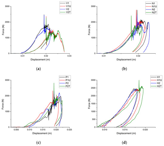
Figure 5.
Force-displacement graphs of (a) virgin, (b) nanofiber-layered, (c) PE-modified, (d) and hybrid specimens.
The nanofiber-interleaved specimens (Figure 5b) displayed a multi-step retraction, where each unloading segment was interrupted by small force rebounds, corresponding to secondary peaks seen during the loading phase. These rebounds were attributed to progressive failures within the electrospun PAN mat; each time a bundle of nanofibers debonded, local compliance increased, generating a short, recoverable displacement before the next bundle was engaged. Because the mat constrains crack opening, the overall retraction remains relatively steep, suggesting that most deformation was reversible. After thermal treatment (N2T), the retraction became straighter and longer, indicating reduced interfacial friction.
In the PE-modified specimens (Figure 5c), the unloading branch following the first peak did not drop vertically but instead curved back toward the displacement axis, forming a wide, ductile retraction. This curved behavior is indicative of localized matrix shear yielding around PE domains. Once the crack front stabilized, the softened PE/epoxy blend continued to carry load, and the laminate sprang back gradually, resulting in a broader retraction radius than that of the virgin laminate. Upon re-impact, the same specimen (P1U) exhibited an even wider retraction, consistent with permanent plasticization of the interfacial region. In contrast, the treated specimen (P2T) showed a shorter yet higher retraction arc. After re-impact, the same specimen (P1U) shows a still broader retract, consistent with permanent plasticization of the inter region. By contrast, the treated specimen (P2T) exhibits a shorter but higher retract arc which might be the evidence that molten PE has refilled micro-voids, stiffened the interface and allowed the laminate to deal with load elastically before complete unloading.
The untreated hybrid specimens (Figure 5d) combined the ductile curvature characteristic of PE laminates with the steep recovery profile of nanofiber-reinforced laminates, producing a smooth, parabolic retraction that concluded with the smallest permanent indentation among all groups. Notably, the treated specimen (H2T) retained this parabolic shape while elevating the entire curve, suggesting that the laminate initially released load rapidly, then transitioned into a prolonged, gentle tail without intermediate rebounds. This behavior confirms that molten PE infiltrated the nanofiber network, fused delaminated regions, and restored continuous load paths. The absence of oscillations or abrupt compliance shifts throughout retraction highlights the re-establishment of cohesive load-bearing capability and explains why the hybrid laminate recovered both stiffness and energy absorption capacity following treatment. The gradual post-peak descent further supports distributed energy dissipation rather than sudden fiber pull-out.
These findings imply that PE particles enhanced ductility and provided reversible flow, electrospun PAN nanofiber mats constrain delamination, and their synergistic integration achieves both prominent impact resistance and effective thermal self-healing.
3.3. Energy-Time
The energy-time graphs confirm the trends observed in the force-time curves and offer additional insight into how each laminate architecture stores and dissipates the 11 J of impact energy.
For the virgin specimens (Figure 6a), the absorbed energy curves for the first-impact specimens (V1, V2) exhibit an almost linear increase followed by a plateau, indicating that nearly all of the input energy is absorbed through damage formation and plastic deformation. Upon re-impact (V1U), the curve reaches its peak slightly earlier, implying that the tip rebounds from a now more compliant, damage-weakened target. Thermal conditioning (V2T) shifts the entire trace rightward without increasing the peak value, confirming that heating does not restore structural stiffness but merely delays energy uptake by alleviating residual stresses.
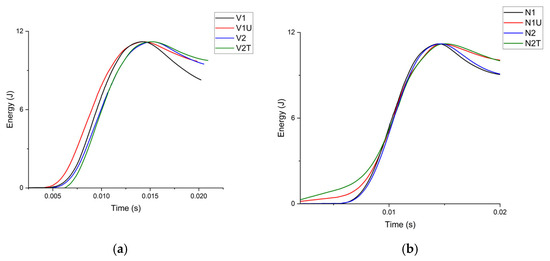
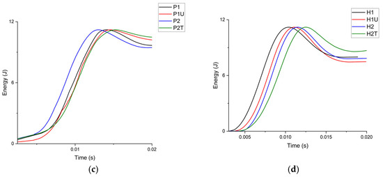
Figure 6.
Energy-time graphs of (a) virgin, (b) nanofiber-layered, (c) PE-modified, (d) and hybrid specimens.
Despite the observed degradation in force resistance, the virgin specimens continue to absorb comparable amounts of total energy, albeit over a longer time span. This suggests that energy absorption shifts from instantaneous to more time-dependent mechanisms, likely involving progressive matrix yielding and interfacial failures.
In the nanofiber-interleaved specimens (Figure 6b), all four curves converge almost precisely at the same final energy value. The near-identical energy profiles, regardless of whether the specimens were damaged or thermally conditioned, underscore the role of PAN nanofibers as structurally robust, non-thermoplastic bridging elements. Their ability to suppress delamination and bridge developing cracks enables consistent and uniform energy dissipation across all conditions.
Notably, the second impacts exhibit slightly increased energy absorption, which is likely attributed to the concurrent development of additional matrix and fiber cracks along with progressive damage to the nanofiber mat itself.
The PE-modified specimens (Figure 6c) demonstrate a distinct energy absorption profile. The untreated specimens (P1, P2) absorb energy more rapidly than their virgin counterparts, a behavior attributed to viscoelastic deformation and frictional sliding at the PE/epoxy interfaces prior to rebound. This early dissipation indicates that pre-existing microcracks within the PE-modified matrix allow energy to be released earlier, while also permitting partial elastic recovery. After thermal treatment, the curve for the treated specimen (P2T) approaches the original plateau but begins to decline earlier, suggesting that molten PE reduces matrix viscosity, thereby enabling limited crack closure. However, this softening also facilitates time-dependent flow, which vents a portion of the stored energy during unloading. Overall, the incorporation of PE contributes to energy absorption through viscoelastic damping and plastic deformation. Heating further softens the PE domains, helping the thermally treated specimens retain favorable energy uptake behavior under repeated impact.
The hybrid specimens (Figure 6d) demonstrated the most advantageous behavior. Both untreated specimens (H1, H2) rapidly absorbed energy, and their energy-time curves decayed smoothly as rebound energy was recovered, which provided evidence that the structure not only stored but also released energy in a controlled, elastic manner. The re-impact of the first specimen (H1U) reproduced this profile with a 4% reduction in peak force, confirming superior damage tolerance. Moreover, the treated specimen (H2T) maintained a broader plateau prior to decay, implying that molten PE had infiltrated along the nanofiber mat, sealed crack faces, and re-established an efficient load path that both accumulated and released strain energy without catastrophic dissipation.
Collectively, the energy analyses indicated that only the hybrid architecture combined high energy uptake with elastic recovery and post-thermal restoration. Therefore, their synergistic integration yielded a laminate capable of rapidly storing the full impact energy. Heat appeared to enhance interfacial compatibility, resulting in H2T exhibiting the smoothest and longest energy dissipation curve.
3.4. Energy-Displacement
The energy-displacement diagrams provide complementary insights to the force-time and energy-time graphs, as the slope of each curve corresponds to the instantaneous contact force, while the extent to which the lines return after the peak reflects the degree of permanent indentation in the plate. Taken together, these characteristics reveal how each laminate architecture balances stiffness and damage progression.
For the untreated virgin specimens (Figure 7a), the first-impact traces (V1, V2) rose sharply and almost linearly to their peak, after which the curves became concave and dropped slightly, a behavior that is typical of brittle, fiber-dominated failure followed by partial elastic rebound. In contrast, thermal treatment (V2T) shifted the curve further rightward, indicating matrix softening and a reduction in bending stiffness rather than any healing effect. Virgin epoxy laminates demonstrated high energy absorption but limited toughness. Post-impact (V1U) and thermally conditioned (V2T) specimens revealed a decreased displacement and increased curvature, suggesting interfacial debonding and coalescence of microcracks.
Figure 7.
Energy-displacement graphs of (a) virgin, (b) nanofiber-layered, (c) PE-modified, and (d) hybrid specimens.
The nanofiber-interleaved specimens exhibited notably consistent behavior across all four traces (Figure 7b). Their curves are closely clustered and exhibited nearly identical slopes, even for the thermally treated specimen (N2T), which followed the same trajectory after a slightly delayed onset. This suggests that the nanofiber interleaf helped preserve structural integrity and mitigates stiffness degradation, although it introduced some additional compliance after the nanofibers have fractured.
In the PE-modified system (Figure 7c), the untreated specimens (P1 and P2) exhibited the steepest initial slope of the group. This steeper ascent reflected higher average force transmission and was attributed to localized shear-yielding around PE domains that rapidly engaged the E-glass layers. For the re-impacted specimen (P1U), the curvature was smoother, implying distributed, ductile damage rather than abrupt delamination. The treated specimen (P2T) absorbed energy much more gradually, indicating that molten PE had decreased the matrix modulus, delaying load transfer in the early stage but ultimately allowing larger transverse deflection and hence a comparable total energy budget. PE enhanced the ductile deformation capacity of the composite. The longer tail of P2T was indicative of energy dissipation through plastic flow and interfacial slippage. Heat likely contributed by softening the PE domains and improving interphase compatibility.
For the hybrid specimens (Figure 7d), the untreated specimens (H1 and H2) showed the lowest displacement of all groups. Re-impact (H1U) revealed only minimal loss, confirming superior damage tolerance. After thermal activation, H2T surpassed its own untreated twin. This increase in final energy, coupled with early-stage softening, suggested that molten PE had infiltrated the nanofiber network, partially healed crack faces, and enabled further deflection before puncture without compromising ultimate load capacity. The combination of PE and nanofibers provided excellent toughness and post-impact durability. The high slope and wide displacement demonstrated damage tolerance with stable energy absorption. Hybrid samples outperformed the others in absorbed energy, progressive deformation, and damage mitigation, making them optimal for reusable or cyclic impact applications.
3.5. SEM Analysis
SEM is essential for post-impact analysis because its sub-micrometer resolution and large depth of field reveal key failure features such as fiber/matrix debonding, matrix fracture morphology, nanofiber bridging, and thermoplastic flow. These microstructural insights help validate the toughening and self-healing mechanisms inferred from the graphs, thereby linking the observed effects of reinforcements to the measured improvements in impact strength and thermal recovery.
For untreated virgin specimens (Figure 8a), the fracture surface is dominated by epoxy facets and extensive flat fiber imprints. Long split cracks run parallel to the fiber bundles, and fiber pull-out is evident. These features confirm brittle matrix cleavage combined with abrupt interlaminar delamination.
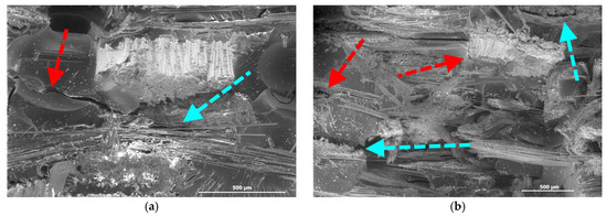
Figure 8.
Virgin (a) untreated and (b) treated specimens (red arrows: matrix cracks, cyan arrows: delaminations).
Thermal exposure of the treated virgin specimens (Figure 8b) leaves the macro-morphology essentially unchanged; large planar facets and straight delamination planes persist, indicating that the neat epoxy network lacks sufficient mobility at 150 °C to reflow or blunt existing cracks. This observation aligns with the negligible thermal recovery identified in the previous graphs.
For nanofiber-interlayered specimens (Figure 9a), a dense, web-like nanofiber mat is clearly discernible between the glass fiber layers. Numerous short fibers bridge the fracture gap, while the epoxy displays rough river patterns, which are characteristic signatures of crack deflection at the mat interface [52].
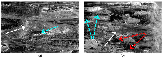
Figure 9.
Nanofiber-interlayered (a) untreated and (b) treated specimens (red arrows: matrix cracks, cyan arrows: delaminations, white arrow: nanofiber mat).
Following thermal treatment (Figure 9b), the nanofiber mat remains intact, and the damage mechanisms are still visible. Matrix cracks and fiber fractures are observed, and fiber pull-out debris accumulates along the interleaf region. Some delaminations appear in both untreated and treated specimens, particularly at the epoxy-nanofiber interface. Considering that neither the nanofiber mat nor the epoxy matrix melts at 150 °C, a similar fracture morphology is expected to persist in the treated samples.
For PE-modified specimens (Figure 10a), the matrix contains numerous rough, ductile ligaments surrounding partially debonded fibers. Rounded micro-voids, typical of PE domains pulled from the epoxy matrix, are dispersed throughout. Extended fiber pull-out is also present, corroborating the oscillations observed in the force-time graphs.
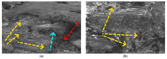
Figure 10.
PE-modified (a) untreated and (b) treated specimens (red arrows: matrix cracks, cyan arrows: delaminations, yellow arrows: PE).
After thermal exposure at 150 °C for 30 min, the treated specimens (Figure 10b) display a fracture surface coated with a continuous, filmy layer bridging adjacent fiber bundles. Smeared resin strings and rounded PE blisters appear between plies, demonstrating that molten PE has migrated and partially filled micro-cracks. This observation rationalizes the ~25% increase in peak force (P2T) and the dual-peak profile seen in the force-time curves, where initial stiffening was followed by a delayed global maximum.
The untreated specimen (Figure 11a) reveals a nanofiber mat that remains largely intact but is bordered by multiple delamination steps propagating both above and below the mat. The fracture path skirts the nanofiber layer rather than penetrating it, confirming the mat’s crack-deflection role; however, the presence of several delaminated plies indicates that the matrix–mat interface is only partially effective in capturing delaminations. Localized fiber cracks originate where axial glass filaments intersect the nanofiber mat, suggesting that load transfer across this interface was still stress-concentrating under the first impact.
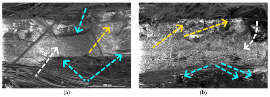
Figure 11.
Hybrid (a) untreated and (b) treated specimens (red arrows: matrix cracks, cyan arrows: delaminations, white arrow: nanofiber mat, yellow arrows: PE).
After thermal treatment (Figure 11b), distinct changes in damage morphology are observed. A continuous, morphologically smooth PE film blankets the nanofiber mat and infiltrates adjacent ply gaps, visually sealing regions that were previously identified as delamination sites. The formerly sharp crack fronts now terminate in resin fillets, and the nanofiber mat is embedded in this re-solidified thermoplastic matrix, evidence that molten PE wicked along the nanofiber mat during heating. Although isolated fiber cracks remain, their tips appear blunted by the PE-rich phase rather than terminating abruptly in air gaps. Relative to the untreated surface, the number and width of open delamination steps are reduced, and matrix shear cusps are still observable, albeit in smaller numbers.
These microstructural observations support the mechanical trends observed earlier. The treated hybrid specimen (H2T) exhibited a ~17% increase in peak impact force and a recovery of energy-absorption capacity. The SEM evidence confirms that the synergistic PAN-guided migration of molten PE both mitigated existing delaminations and improved matrix–fiber load transfer, translating directly into the enhanced post-healing stiffness and strength recorded in the force-time graphs.
These observations confirm the complementary roles of the two modifiers. Polyethylene provides a mobile, thermoplastic phase capable of flowing into crack cavities when heated, whereas the PAN nanofiber mat acts as a mechanical barrier that minimizes delamination during impact and facilitates percolation pathways for the molten PE.
4. Discussion
The findings of this study provide compelling evidence that the dual modification of GFRP laminates through the incorporation of polyethylene (PE) powder and electrospun polyacrylonitrile (PAN) nanofiber mats can significantly enhance both impact resistance and thermal self-healing capabilities. Compared to the poor performance of virgin composites, the modified systems exhibited superior damage tolerance and partial mechanical recovery. PE-modified specimens demonstrated viscoelastic deformation and thermoplastic flow, which helped limit strength loss and enabled a significant increase in peak load following thermal treatment. Meanwhile, PAN-interleaved laminates effectively suppressed initial damage propagation, although they showed limited recovery after heating. A detailed comparison of load-bearing capacity and energy absorption values for each specimen group is presented in Table 2 to support these findings.
Table 2.
Quantitative evaluation of load capacity and energy absorption capabilities of the specimens under low-velocity impact.
Upon examining the table, it can be seen that virgin composites exhibited the lowest post-impact performance, with up to a 30% reduction in load capacity after repeated or thermally treated impacts (V1U, V2T), underscoring the brittle nature of neat epoxy and its limited ability to recover after treatment. Although a slight increase in energy absorption was observed after impact, this was likely due to matrix cracking increasing, rather than meaningful recovery.
Nanofiber-interleaved specimens demonstrated improved damage tolerance, the untreated specimens retaining up to 10% more load capacity, and the electrospun PAN mat effectively delayed delamination and distributed stress, resulting in enhanced energy absorption (up to +20%) compared to the virgin specimens. However, thermal conditioning of these samples (N2T) resulted in a ~15% reduction in peak load. Although the microstructural integrity was largely preserved, the absence of a healing agent combined with thermal expansion mismatches likely contributed to the observed decline in performance.
PE-modified specimens showed a markedly different response. P1U exhibited a 20% drop in load capacity. Post-healing improvements were more pronounced in P2T, with energy absorption increasing by 8%, and load capacity recovering to its pre-impact level. These findings affirm that molten PE could be successful in working as a healing agent, albeit with limited influence on restoring maximum load-bearing strength.
The hybrid laminates, which integrated both polyethylene powder and electrospun PAN nanofiber mats, exhibited the most promising performance among all configurations. These specimens retained approximately 96% of their initial peak strength after re-impact and exhibited an additional 17% increase following thermal treatment, resulting in more than a 40% improvement in load-bearing capacity compared to the untreated virgin specimens. This performance surpasses that of the single-modified systems. Although the absorbed energy of the hybrid specimens decreased by ~10% relative to the untreated virgin specimens, this was accompanied by the lowest permanent indentation and superior resistance to initial damage. This behavior suggests a favorable balance between stiffness and toughness. For the thermally treated hybrid specimens, a notable increase of ~17% in absorbed energy was recorded relative to its untreated counterpart, marking the first such enhancement within this group. The overall improvement in performance can be attributed to the synergistic functions of the two modifiers: PAN nanofibers act as crack-bridging and delamination-resistant reinforcements, while polyethylene serves as a thermally responsive healing phase capable of flowing into damaged regions and restoring interfacial continuity under moderate heating conditions at 150 °C for 30 min.
SEM analysis supported these findings. In the hybrid samples, a continuous PE-rich film was observed infiltrating along the nanofiber network, correlating with the smooth, bell-shaped force-time profiles and minimal permanent indentation measured during testing. Compared to the virgin and single-modified laminates, the hybrid structure exhibited more cohesive energy dissipation, reduced force oscillations, and restored load-bearing pathways—indicative of effective healing and improved structural integrity.
Energy-based evaluations further highlighted the advantages of the hybrid system. Unlike the virgin laminates, which predominantly absorbed energy through brittle matrix failure, or the PE-modified specimens, which relied on viscoelastic mechanisms, the hybrid laminates demonstrated both high energy absorption and elastic recovery. Although they absorbed slightly less total energy than some single-modified samples, this was accompanied by the lowest residual indentation, suggesting a more efficient balance between stiffness and toughness.
Despite these favorable outcomes, some trade-offs were noted. The PAN mat, while beneficial for damage suppression, caused a reduction in stiffness after thermal exposure; possibly due to interfacial relaxation or thermal expansion mismatch. In contrast, the addition of PE improved post-impact healing but introduced time-dependent viscoelastic effects that may affect long-term dimensional stability. The hybrid configuration effectively balanced these opposing tendencies, but its performance remained sensitive to the proportion and distribution of each modifier. Small deviations in PE content or fiber mat uniformity could lead to variability in mechanical response.
While the inclusion of PE offers substantial functional benefits, it also presents limitations that must be considered. The tensile strength of PE-modified laminates was reduced, likely due to the disruption of epoxy network continuity and the formation of weaker interfacial regions. Additionally, the use of thermoplastics increases processing complexity and material costs, potentially hindering large-scale application. Nevertheless, PE’s ability to restore mechanical performance through moderate thermal activation and its contribution to ductile energy dissipation justify its use in scenarios where repairability and impact durability are prioritized over maximum tensile performance. When used in conjunction with PAN nanofibers, these drawbacks are mitigated by the mechanical robustness and damage-controlling effects of the interleaf, resulting in a net gain in performance.
In light of these findings, the hybrid modification strategy presents a promising and scalable approach for the development of advanced GFRP laminates with improved impact performance and thermal restorability. Its compatibility with standard composite manufacturing processes and its activation under moderate heating conditions make it well suited for use in aerospace interiors, automotive panels, wind turbine structures, and other applications where repeated impact and limited maintenance access are of concern. Future studies should focus on evaluating long-term durability under environmental exposure, performance under higher-energy impacts, and the feasibility of industrial-scale production methods such as resin transfer molding or autoclave processing.
5. Conclusions
A systematic comparison of four glass/epoxy laminate architectures—(i) virgin, (ii) PE-modified, (iii) nanofiber-interleaved, and (iv) hybrid—demonstrated that the simultaneous incorporation of a thermoplastic healing agent and an electrospun nanofiber mat provided a balanced impact performance along with acceptable thermal self-recovery.
The virgin specimens exhibited a substantial strength loss of up to 30% upon re-impact. The incorporation of polyethylene reduced this loss to 20%, while the inclusion of nanofibers further limited it to 15%. Notably, the hybrid configuration demonstrated the highest damage tolerance, retaining most of its initial strength with only a 4% reduction. These results indicate a significant enhancement in structural resilience achieved through material modification.
Thermal healing efficiency (150 °C, 30 min): After conditioning, peak force changed by −30% for virgin, +25% for PE-modified, −8% for nanofiber-interleaved, and +17% for hybrid laminates. PE alone contributed to crack filling, but its effect was magnified when the nanofiber mat facilitated continuous flow pathways.
Energy absorption: The untreated virgin specimens exhibited low toughness. In contrast, the modified systems demonstrated improved performance. Energy absorption increased by 9% in the nanofiber-interleaved specimens, while it decreased by 3% in the PE-modified and 3% in the hybrid specimens. Upon thermal treatment, all modified groups (N, P, H) absorbed more energy than their untreated counterparts, with increases of 9%, 8%, and 17% for the PAN-interleaved, PE-modified, and hybrid specimens, respectively.
Force-profile morphology: High-frequency oscillations in virgin, nanofiber-interleaved, and PE-modified laminates revealed brittle, segmental failures; multi-peak behavior in nanofiber specimens indicated staged crack capture. In contrast, the smooth, bell-shaped force curves of the hybrid laminates confirmed cohesive load transfer and stable energy dissipation. With the lowest permanent indentation and with better initial damage resistance, hybrid specimens performed better, indicating a better stiffness-to-toughness balance.
Overall, the revised data reinforced the conclusion that hybrid composites outperformed single-modifier systems: polyethylene served as a mobile, thermoplastic healing agent, while electrospun PAN nanofibers offered a continuous, mechanically robust interleaf that not only retarded crack propagation but also channeled molten PE during thermal activation. This synergy produced a laminate that not only withstood the highest impact loads at the smallest deflections but also demonstrated authentic, application-ready self-healing under a modest 150 °C, 30 min thermal cycle and showed strong potential for reuse in lightweight composite structures exposed to accidental impacts.
Author Contributions
Conceptualization, methodology, software, validation, formal analysis, investigation, data curation, writing—original draft preparation, writing—review and editing, M.Y. and A.Y.; visualization, supervision, writing—review and editing, M.Y. and A.Y. All authors have read and agreed to the published version of the manuscript.
Funding
This research received no external funding.
Institutional Review Board Statement
Not applicable.
Data Availability Statement
The original contributions presented in this study are included in the article. Further inquiries can be directed to the corresponding author.
Conflicts of Interest
The authors declare no conflicts of interest.
References
- Blaiszik, B.J.; Kramer, S.L.; Olugebefola, S.C.; Moore, J.S.; Sottos, N.R.; White, S.R. Self-healing polymers and composites. Annu. Rev. Mater. Res. 2010, 40, 179–211. [Google Scholar] [CrossRef]
- Agarwal, B.D.; Broutman, L.J.; Chandrashekhara, K. Analysis and Performance of Fiber Composites, 4th ed.; Wiley: Hoboken, NJ, USA, 2017; ISBN 978-1-119-38998-9. [Google Scholar]
- Dubinskii, S.; Feygenbaum, Y.; Senik, V.; Metelkin, E. A study of accidental impact scenarios for composite wing damage tolerance evaluation. Aeronaut. J. 2019, 123, 1724–1739. [Google Scholar] [CrossRef]
- Zhao, E.; Xia, Q.; Liu, L.; Jin, F.; Luo, G.; Zhao, Z.; Chen, W. Experimental study on multiple self-healing and impact properties of 2D carbon fiber fabric-reinforced epoxy composites with shape memory properties. Thin-Walled Struct. 2024, 205, 112549. [Google Scholar] [CrossRef]
- Thorn, T.D.S.; Liu, Y.; Yao, X.; Papageorgiou, D.G.; Robinson, P.; Bilotti, E.; Peijs, T.; Zhang, H. Smart and repeatable easy-repairing and self-sensing composites with enhanced mechanical performance for extended components life. Compos. Part A Appl. Sci. Manuf. 2023, 165, 107337. [Google Scholar] [CrossRef]
- Shojaei, A.; Khasraghi, S.S. Self-healing and self-sensing smart polymer composites. In Composite Materials: Manufacturing, Properties and Applications; Low, I.M., Dong, Y., Eds.; Elsevier: Oxford, UK, 2021; Chapter 13; pp. 307–357. ISBN 978-0-12-820512-9. [Google Scholar] [CrossRef]
- Paolillo, S.; Bose, R.K.; Santana, M.H.; Grande, A.M. Intrinsic Self-Healing Epoxies in Polymer Matrix Composites (PMCs) for Aerospace Applications. Polymers 2021, 13, 201. [Google Scholar] [CrossRef] [PubMed]
- Wang, J.; Tang, J.; Chen, D.; Xing, S.; Liu, X.; Hao, J. Intrinsic and extrinsic self-healing fiber-reinforced polymer composites: A review. Polym. Compos. 2023, 44, 6304–6323. [Google Scholar] [CrossRef]
- do Nascimento, A.A.; Fernandez, F.; da Silva, F.S.; Ferreira, E.P.; Melo, J.D.D.; Barbosa, A.P.C. Addition of poly (ethylene-co-methacrylic acid)(EMAA) as self-healing agent to carbon-epoxy composites. Compos. Part A Appl. Sci. Manuf. 2020, 137, 106016. [Google Scholar] [CrossRef]
- Nascimento, A.A.D.; Trappe, V.; Melo, J.D.D.; Barbosa, A.P.C. Fatigue behavior of self-healing glass fiber/epoxy composites with addition of poly (ethylene-co-methacrylic acid)(EMAA). Polym. Test. 2023, 117, 107863. [Google Scholar] [CrossRef]
- Meure, S.; Furman, S.; Khor, S. Poly[ethylene-co-(methacrylic acid)] healing agents for mendable carbon fiber laminates. Macromol. Mater. Eng. 2010, 295, 420–424. [Google Scholar] [CrossRef]
- Vishe, N.J.; Jony, B.; Thapa, M.; Mulani, S.B.; Roy, S. Healing of mode-I fatigue crack in fiber-reinforced composites using thermoplastic healants. In Proceedings of the AIAA SciTech 2020 Forum, Orlando, FL, USA, 6–10 January 2020; pp. 1–10. [Google Scholar] [CrossRef]
- Vishe, N.J.; Mulani, S.B.; Roy, S. Self-Healing of Fatigue Delamination in Thermoset Composites Using Thermoplastic Healants. In Proceedings of the ASME 2023 Aerospace Structures, Structural Dynamics, and Materials Conference, San Diego, CA, USA, 19–21 June 2023. [Google Scholar] [CrossRef]
- Chuves, Y.P.; Monticeli, F.M.; do Nascimento, A.A.; Barbosa, A.P.C.; Voorwald, H.J.C.; Cioffi, M.O.H. The Effect of Self-Healing Agent Fraction on CFRP Mechanical Behavior: Statistical Analysis Approach. Fibers Polym. 2023, 24, 729–740. [Google Scholar] [CrossRef]
- Pingkarawat, K.; Bhat, T.; Craze, D.A.; Wang, C.H.; Varley, R.J.; Mouritz, A.P. Healing of carbon fibre-epoxy composites using thermoplastic additives. Polym. Chem. 2013, 4, 5007–5015. [Google Scholar] [CrossRef]
- Varley, R.J.; Craze, D.A.; Mouritz, A.P.; Wang, C.H. Thermoplastic Healing in Epoxy Networks: Exploring Performance and Mechanism of Alternative Healing Agents. Macromol. Mater. Eng. 2013, 298, 1232–1242. [Google Scholar] [CrossRef]
- Pingkarawat, K.; Wang, C.H.; Varley, R.J.; Mouritz, A.P. Mechanical properties of mendable composites containing self-healing thermoplastic agents. Compos. Part A Appl. Sci. Manuf. 2014, 65, 10–18. [Google Scholar] [CrossRef]
- Zhang, X.; Zhao, G.; Lai, J.; Yu, T.X.; Zhang, X. Interlaminar toughening and self-healing mechanism for hard-and-soft layered composite laminates. Compos. Part A Appl. Sci. Manuf. 2025, 189, 108623. [Google Scholar] [CrossRef]
- Chang, K.M.; Sottos, N.R. Self-healing of transverse crack damage in carbon fiber composites. Compos. Sci. Technol. 2023, 242, 110158. [Google Scholar] [CrossRef]
- Zhang, H.; Lin, Z.; Xiao, K.; Shi, S. A Healable Epoxy with Comprehensive Properties by Incorporating Thermoplastic Epoxy Microspheres. Macromol. Mater. Eng. 2022, 307, 2100907. [Google Scholar] [CrossRef]
- Jony, B.; Thapa, M.; Mulani, S.B.; Roy, S. Repeatable self-healing of thermosetting fiber reinforced polymer composites with thermoplastic healant. Smart Mater. Struct. 2019, 28, 025037. [Google Scholar] [CrossRef]
- Ramesh, M.; Rajeshkumar, L.N.; Srinivasan, N.; Kumar, D.V.; Balaji, D. Influence of filler material on properties of fiber-reinforced polymer composites: A review. E-Polym. 2022, 22, 898–916. [Google Scholar] [CrossRef]
- Rashid Abin Haque, M.; Islam, S.M.M.; Uddin Labib, K.M.R. Nanotechnology-enhanced fiber-reinforced polymer composites: Recent advancements on processing techniques and applications. Heliyon 2024, 10, e24692. [Google Scholar] [CrossRef]
- Hodgkin, J.H.; Simon, G.P.; Varley, R.J. Thermoplastic toughening of epoxy resins: A critical review. Polym. Adv. Technol. 1998, 9, 3–10. [Google Scholar] [CrossRef]
- Pingkarawat, K.; Wang, C.H.; Varley, R.J.; Mouritz, A.P. Self-healing of delamination fatigue cracks in carbon fibre-epoxy laminate using mendable thermoplastic. J. Mater. Sci. 2012, 47, 4449–4456. [Google Scholar] [CrossRef]
- Meure, S.; Wu, D.Y.; Furman, S. Polyethylene-co-methacrylic acid healing agents for mendable epoxy resins. Acta Mater. 2009, 57, 4312–4320. [Google Scholar] [CrossRef]
- Cohades, A.; Manfredi, E.; Plummer, C.J.G.; Michaud, V. Thermal mending in immiscibl.e poly(ϵ-caprolactone)/epoxy blends. Eur. Polym. J. 2016, 81, 114–128. [Google Scholar] [CrossRef]
- Cohades, A.; Michaud, V. Damage recovery after impact in E-glass reinforced poly(ε-caprolactone)/epoxy blends. Compos. Struct. 2017, 180, 439–447. [Google Scholar] [CrossRef]
- Zhang, F.; Zhang, L.; Yaseen, M.; Huang, K. A review on the self-healing ability of epoxy polymers. J. Appl. Polym. Sci. 2021, 138, 50260. [Google Scholar] [CrossRef]
- Meure, S.; Varley, R.J.; Wu, D.Y.; Mayo, S.; Nairn, K.; Furman, S. Confirmation of the healing mechanism in a mendable EMAA-epoxy resin. Eur. Polym. J. 2012, 48, 524–531. [Google Scholar] [CrossRef]
- Snyder, A.D.; Turicek, J.S.; Diesendruck, C.E.; Varley, R.J.; Patrick, J.F. Unraveling chemical and rheological mechanisms of self-healing with EMAA thermoplastics in fiber-reinforced epoxy composites. Compos. Part A Appl. Sci. Manuf. 2024, 185, 108271. [Google Scholar] [CrossRef]
- Nascimento, A.; Trappe, V.; Pavasaryte, L.; Melo, J.; Barbosa, A.P.C. Effects of particle size and particle concentration of poly (ethylene-co-methacrylic acid) on properties of epoxy resin. J. Appl. Polym. Sci. 2024, 141, e55677. [Google Scholar] [CrossRef]
- Zucchelli, A.; Focarete, M.L.; Gualandi, C.; Ramakrishna, S. Electrospun nanofibers for enhancing structural performance of composite materials. Polym. Adv. Technol. 2011, 22, 339–349. [Google Scholar] [CrossRef]
- Erdal, M.O.; Yazman, Ş.; Gemi, L.; Yapici, A. The Effect of Nonwoven Electrospun PAN Nanofiber Mat on Mechanical and Thermal Properties of Epoxy Composites. Süleyman Demirel Üniversitesi Fen Bilim. Enstitüsü Derg. 2018, 22, 528–535. [Google Scholar] [CrossRef]
- Yildiz, M.; Yapici, A.; Özkan, V.; Şahin, Ö.S. Low velocity impact and tensile performance of gfrps interleaved with electrospun nylon 6,6 nanofiber mats. Teh. Vjesn. 2021, 28, 733–738. [Google Scholar] [CrossRef]
- Eskizeybek, V.; Yar, A.; Avcı, A. CNT-PAN hybrid nanofibrous mat interleaved carbon/epoxy laminates with improved Mode I interlaminar fracture toughness. Compos. Sci. Technol. 2018, 157, 30–39. [Google Scholar] [CrossRef]
- Muthu, J.S.D.; Bradely, P.; Jinasena, I.I.K.; Wegner, L.D. Electro spun nanomats strengthened glass fiber hybrid composites: Improved mechanical properties using continuous nanofibers. Polym. Compos. 2020, 41, 958–971. [Google Scholar] [CrossRef]
- Ma, Y.; Zhuang, Y.; Li, C.; Luo, C.; Shen, X. Interlaminar Mechanical Properties and Toughening Mechanism of Highly Thermally Stable Composite Modified by Polyacrylonitrile Nanofiber Films. Polymers 2022, 14, 1348. [Google Scholar] [CrossRef] [PubMed]
- Khan, Z.; Kafiah, F.; Zahid Shafi, H.; Nufaiei, F.; Ahmed Furquan, S.; Matin, A. Morphology, Mechanical Properties and Surface Characteristics of Electrospun Polyacrylonitrile (PAN) Nanofiber Mats. Int. J. Adv. Eng. Nano Technol. 2015, 2, 15–22. [Google Scholar]
- Isaac, B.; Taylor, R.M.; Reifsnider, K. Anisotropic Characterizations of Electrospun PAN Nanofiber Mats Using Design of Experiments. Nanomaterials 2020, 10, 2273. [Google Scholar] [CrossRef] [PubMed]
- Sharma, D.K.; Shen, J.; Li, F. Reinforcement of Nafion into polyacrylonitrile (PAN) to fabricate them into nanofiber mats by electrospinning: Characterization of enhanced mechanical and adsorption properties. RSC Adv. 2014, 4, 39110–39117. [Google Scholar] [CrossRef]
- Herwan, J.; Al-Bahkali, E.; Khalil, K.A.; Souli, M. Load bearing enhancement of pin joined composite laminates using electrospun polyacrylonitrile nanofiber mats. Arab. J. Chem. 2016, 9, 262–268. [Google Scholar] [CrossRef]
- Shakil, U.A.; Hassan, S.B.A.; Yahya, M.Y.; Nauman, S. Mechanical properties of electrospun nanofiber reinforced/interleaved epoxy matrix composites—A review. Polym. Compos. 2020, 41, 2288–2315. [Google Scholar] [CrossRef]
- Arpatappeh, F.A.; Gharehaghaji, A.A.; Nosraty, H. Epoxy-matrix nanocomposites reinforced by electrospun polymeric nanofibrous layers: PAN, PA-6,6, and hybrid PAN/PA-6,6. Proc. Inst. Mech. Eng. Part C J. Mech. Eng. Sci. 2022, 236, 3615–3622. [Google Scholar] [CrossRef]
- Gemi, L.; Azeem, M.; Yazman, Ş.; Kayrıcı, M.; Gök, O. Investigation of Mechanical Properties and Damage Development of Filament Wound GFRP Composite Pipes by Ring Tensile Test. Necmettin Erbakan Üniversitesi Fen Ve Mühendislik Bilim. Derg. 2024, 6, 93–104. [Google Scholar] [CrossRef]
- Sanchaniya, J.V.; Dobariya, S.P.; Lasenko, I. Mechanical and Thermal Properties of Nanocomposites Reinforced with Pan Nanofibre Mats. Latv. J. Phys. Tech. Sci. 2024, 61, 92–106. [Google Scholar] [CrossRef]
- Sanchaniya, J.V.; Moothedath, G. Deformation Behaviour of Oriented Electrospun Pan Nanofiber Mats. Latv. J. Phys. Tech. Sci. 2025, 62, 60–66. [Google Scholar] [CrossRef]
- Hotaling, N.A.; Bharti, K.; Kriel, H.; Simon, C.G., Jr. DiameterJ: A validated open source nanofiber diameter measurement tool. Biomaterials 2015, 61, 327–338. [Google Scholar] [CrossRef] [PubMed]
- Lasenko, I.; Sanchaniya, J.V.; Kanukuntla, S.P.; Ladani, Y.; Viluma-Gudmona, A.; Kononova, O.; Lusis, V.; Tipans, I.; Selga, T. The Mechanical Properties of Nanocomposites Reinforced with PA6 Electrospun Nanofibers. Polymers 2023, 15, 673. [Google Scholar] [CrossRef]
- Kayaaslan, M.; Coskun, T.; Unlu, U.M.; Sahin, O.S. Effects of thickness, fibre orientation and fabric textile on the low-velocity impact performances of thermoset and thermoplastic composites. J. Thermoplast. Compos. Mater. 2023, 36, 4408–4429. [Google Scholar] [CrossRef]
- ASTM D7136/D7136M-15; Standard Test Method for Measuring the Damage Resistance of a Fiber-Reinforced Polymer Matrix Composite to a Drop-Weight Impact Event. ASTM International: West Conshohocken, PA, USA, 2015.
- Huang, T.; Bobyr, M. A Review of Delamination Damage of Composite Materials. J. Compos. Sci. 2023, 7, 468. [Google Scholar] [CrossRef]


Disclaimer/Publisher’s Note: The statements, opinions and data contained in all publications are solely those of the individual author(s) and contributor(s) and not of MDPI and/or the editor(s). MDPI and/or the editor(s) disclaim responsibility for any injury to people or property resulting from any ideas, methods, instructions or products referred to in the content. |
© 2025 by the authors. Licensee MDPI, Basel, Switzerland. This article is an open access article distributed under the terms and conditions of the Creative Commons Attribution (CC BY) license (https://creativecommons.org/licenses/by/4.0/).