Article

Experimental and Modeling Study for the Solar-Driven CO2 Electrochemical Reduction to CO

by
Matteo Agliuzza
1,2,*,
Roberto Speranza
1,
Andrea Lamberti
1,2,
Candido Fabrizio Pirri
1,2 and
Adriano Sacco
2,*
1
Applied Science and Technology Department, Politecnico di Torino, Corso Duca degli Abruzzi 24, 10129 Torino, Italy
2
Center for Sustainable Future Technologies @Polito, Istituto Italiano di Tecnologia, Via Livorno 60, 10144 Torino, Italy
*
Authors to whom correspondence should be addressed.
Appl. Sci. 2025, 15(2), 549; https://doi.org/10.3390/app15020549
Submission received: 9 December 2024 / Revised: 1 January 2025 / Accepted: 4 January 2025 / Published: 8 January 2025

Abstract

:
With the rising levels of atmospheric CO2, electrochemistry shows great promise in decarbonizing industrial processes by converting CO2 into valuable products through scalable and sustainable technologies. In this framework, the present study investigates the solar-driven CO2 reduction toward carbon monoxide, achieved by the integration between the electrochemical reactor and dye-sensitized solar cells (DSSCs), both in experimental and modeling perspectives. COMSOL® Multiphysics 6.3 was used to develop a detailed finite element method model of the electrochemical cell integrated with a photovoltaic module, validated with the experimental results that demonstrated a strong correlation. A 2D model was designed, incorporating cathode and anode regions divided by an ion-exchange membrane. The model includes platinum foil and silver nanoparticles as catalysts for the oxygen evolution reaction and CO2 reduction reaction, respectively. Integration with the fundamental equations of the DSSCs was simulated to analyze the solar-driven CO2 reduction behavior under solar irradiance variations, offering a valuable tool for optimizing operating conditions and predicting the device performance under different environmental conditions. The integrated device successfully produces CO with a faradaic efficiency of 73.85% at a current density of J = 3.35 mA/cm2 under 1 sun illumination, with the result validated and reproduced by the mathematical model. Under reduced illumination conditions of 0.8 and 0.6 suns, faradaic efficiencies of 68.5% and 64.1% were achieved, respectively.

1. Introduction

Addressing climate change has become a pressing global necessity, as it impacts numerous facets of life, from food security to geopolitics and economic stability. The consequences of global warming (such as extreme weather, reduced crop yields, water scarcity, rising sea levels, and the extinction of multiple species) stem largely from greenhouse gases, particularly carbon dioxide. CO2 emissions are predominantly generated by fossil fuel combustion, which currently satisfies about 80% of the global energy demand, along with heat and electricity production. As energy consumption continues to climb, atmospheric CO2 levels are rising. In this framework, the electrochemical reduction of CO2 represents a significant advancement toward both environmental sustainability and energy production. In fact, as a response to the escalating global CO2 emissions primarily driven by fossil fuel combustion, the need for renewable energy and carbon-neutral processes has become critical. Electrochemical CO2 reduction (CO2RR), which involves converting CO2 into valuable fuels or chemicals using electricity, offers an innovative pathway to address this issue [1]. This process has shown considerable promise for producing a range of high-value products, including carbon monoxide (CO), formic acid (HCOOH), methane (CH4), and other hydrocarbons [2], under relatively mild conditions of temperature and pressure. A unique advantage of CO2 electroreduction lies in its compatibility with renewable energy sources, especially solar power. By coupling photovoltaic (PV) cells with electrochemical (EC) cells, in fact, it is possible to achieve a self-sustaining process that converts sunlight directly into chemical energy [3,4,5,6]. This approach not only leverages the abundant available solar energy but also mitigates the environmental impact associated with traditional energy production. The PV–EC integration, or “artificial leaf” concept, is an exciting area of research that exemplifies the potential for renewable-driven electrochemical systems for green fuel production. Although extensively utilized for solar-driven water splitting to produce green hydrogen [7,8,9], only one study in the literature shows the total integration between the PV and EC components for solar-driven CO2 conversion [10]. In the typical PV–EC connected configuration, the PV is externally connected to the EC electrodes, with a proper electrical matching between the two components: in this field, the research community has explored different PV and EC generations to maximize the solar-to-fuel efficiency nstc. For example, Wang et al. exploited amorphous Si-based PV to power a flow cell, achieving a nstc = 4.9% at 99.2 mA [11], while Zhang et al. reached a higher nstc = 12.5%, thanks to the employment of third-generation perovskite solar cells connected to a H-type EC [12]. Concerning PV–EC systems with high current densities, Lee et al. exploited a zero-gap reactor powered by a Si-based PV (with active area A = 120 cm2), achieving a nstc = 12.1% at 1.1 A [13].
From a modeling perspective, simulations have been widely exploited to understand the dynamics of the CO2RR in the reactor. Gupta et al. defined a 1D model for the electrolyte–electrode boundary layer [14], predicting the surface concentration of chemical species and laying the foundation for more complex simulations. Burdyny et al. introduced gas bubbles, and a diffusion-dependent boundary layer [15], and more recent studies introduced the full electrochemical cell, also benefiting from COMSOL® Multiphysics software 6.3 [16,17]. Regarding the PV module, the majority of the work in the literature focuses on the extrapolation of the main electrical parameters from the one-diode model [18], emphasizing their dependence on the incident light intensity and temperature [19,20].
Despite several studies reporting the connection between the PV and EC and the modeling of the two components, to the best of our knowledge, there is a lack of a complete simulation of the whole system. In this framework, the present study introduces, for the first time, a comprehensive model for a solar-driven CO2 electroreduction to CO, developed using the COMSOL® Multiphysics software 6.3. The model combines experimental data with advanced simulations, offering an in-depth analysis of the system’s performance under various operating conditions. Key parameters such as the applied voltage, electrolyte flow rate, and cell dimensions have already been examined in previous work [21]: in particular, the model was able to reproduce the experimental results, along with inspecting the chemical conditions inside the electrochemical cell (such as the pH, ionic species diffusion on the boundary layer, etc.). In the present work, two further steps are implemented: (1) A time-dependent analysis, and (2) the integration of a dye-sensitized solar cell (DSSC) module as the energy source, which in this setup, allows for an evaluation of the device’s performance as a function of solar irradiance, supporting the goal of maximizing solar-to-fuel efficiency. For this purpose, the equivalent circuit model for the photovoltaics module is exploited, where the key electrical parameters have been fit to experimental I–V curves. This research not only validates the model against the experimental results but also opens possibilities for future optimization and scale-up of the technology, making it a valuable tool in the pursuit of sustainable, solar-driven chemical production.

2. Materials and Methods

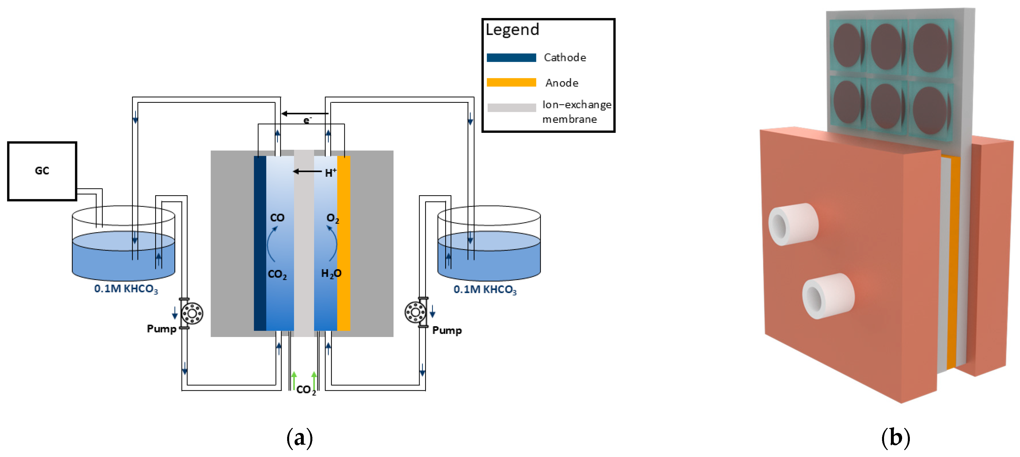
2.1. Electrochemical Cell

The system comprises a batch cell reactor for the CO2RR and a module of 6 DSSCs connected in series for energy harvesting. The electrochemical system is based on a commercial electrochemical reactor (ElectroCell, Ringkoebing-Skjern, Denmark) equipped with ethylene-propylene-diene monomer (EPDM) gaskets to establish separate anodic and cathodic compartments. A Nafion N117 proton-exchange membrane (supplied by Ion Power, New Castle, DE, USA) acts as the separator, ensuring ionic conductivity while preventing the physical mixing of the compartments. The electrolyte is a 0.1 M potassium bicarbonate (KHCO3) solution, prepared using KHCO3 with 99.7% purity (Sigma Aldrich, St. Louis, MO, USA) and dissolved in distilled water. This electrolyte is continuously recirculated between the electrochemical cell and external reservoirs using a peristaltic pump (MCP ISM404B, Ismatec, Glattbrugg, Switzerland) operating at a controlled flow rate of 1.547 mL/min. CO2 is supplied directly into the electrochemical cell through two mass flow controllers (from Bronkhorst, Ruurlo, The Netherlands), each calibrated to maintain a constant flow rate of 15 mL/min, ensuring a steady supply of CO2 to the cathodic compartment. The electrodes are configured to facilitate the targeted electrochemical reactions. For the anode, a commercial platinum foil (Pt) with a geometric area of 9.9 cm2 (GoodFellow, Huntingdon, UK) is used to drive the oxygen evolution reaction (OER). The cathode features silver nanoparticles deposited onto a carbon paper substrate (28BC from SGL Carbon, Wiesbaden, Germany) using a physical sputtering technique. During the deposition process, a current of 50 mA (Idep) is applied for 300 s (Tdep) to achieve uniform nanoparticle coverage. Due to slight variations in the preparation process, the cathodic geometric area ranges between 1.2 and 1.9 cm2 across the experiments. To mitigate the accumulation of gas bubbles in the electrolyte, plastic meshes are inserted into both the anodic and cathodic compartments. Electrochemical experiments are performed using chronoamperometry with aVSP potentiostat (supplied by BioLogic, Seyssinet-Pariset, France). A two-electrode configuration is employed, wherein a controlled voltage is applied across the electrodes, and the current response is recorded over time, typically for a duration of approximately one hour for each applied voltage point. The gaseous products generated at the cathode are analyzed using a Micro Gas Chromatograph (supplied by Inficon Fusion, Bad Ragaz, Switzerland) equipped with two analytical modules: an Rt-Molsieve 5A column and an Rt-Q-Bond column. Each module is coupled with a microthermal conductivity detector to ensure the accurate quantification of gaseous species. To assess the potential formation of liquid products, high-performance liquid chromatography (HPLC) is employed using a Shimadzu (Kyoto, Japan) system with a ReproGel column (300 × 8 mm) and an ultraviolet–visible (UV–Vis) detector set to 210 nm. The mobile phase consists of 9.0 mM H2SO4. The faradaic efficiency (FE) for the different products is calculated through the following formula:
F E = 2 N F Q
where N is the amount of a product detected (number of moles), 2 is the number of electrons required to obtain 1 molecule of this product (CO, HCOOH, or H2 formation), F is the Faraday constant, and Q is the total charge passed through the system recorded during electrolysis.

2.2. Photovoltaic Module

Depending on the type of photovoltaic technology used, the physical phenomena driving photogeneration vary. In this work, DSSCs are utilized. Unlike conventional solar cells made from semiconductive materials, DSSCs are photoelectrochemical devices where charge photogeneration and charge transport are distinct processes. In these cells, electrons are photogenerated in a light-sensitive, ruthenium-based dye and then collected by a layer of TiO2 nanoparticles deposited on a conductive fluorine-doped tin oxide (FTO) glass substrate. The electrons are subsequently regenerated by an iodide/triiodide redox couple in the electrolyte, with a platinum counter electrode facilitating the process. A single DSSC cannot produce sufficient power to drive the electrochemical cell. Therefore, a module comprising six DSSCs connected in series using conductive silver paste is employed. For the preparation of the DSSC, Pt films were sputtered on a conductive FTO glass substrate (TCO30-10, 3mm, 10 ohm/sq., from Solaronix, Aubonne, Switzerland), with Tdep = 20 s and Idep = 30 mA: the glasses were masked to form a 1 cm2 circular shaped film; the FTO was also drilled to enable the electrolyte injection. For the photoanode, TiO2 paste (Ti-Nanoxide from Solaronix, Aubonne, Switzerland) layers were deposited through the doctor blade technique and subsequently dried on a hot plate at 100 °C for solvent evaporation. After the photoanodes were fired (performed at 475 °C for 30 min), they were immersed in a 0.3 mM solution of Ru-based dye (N719, Ruthenizer 535-bisTBA from Solaronix, Aubonne, Switzerland) in ethanol for at least 17 h to ensure complete absorption on the TiO2 surface. Photoanodes and Pt cathodes were then sealed through a thermoplastic sealant (Meltonix 1170-60, Solaronix, Aubonne, Switzerland) under a hot press at approx. 110 °C. Finally, the cell was filled with electrolyte, which is a mixture of 0.45M Sodium Iodide (NaI), 0.056M Iodine (I2), and 0.55M 4-tert-butylpyridine (TBP) in 3-Methoxypropionitrile (CH3OCH2CH2CN), purchased from Sigma-Aldrich (St. Louis, MO, USA). The final module was characterized by measuring the current–voltage (I–V) characteristics under varying levels of irradiance (expressed in Suns, where 1 Sun = 1 kW/m2) with an LED solar simulator of class ABA from Oriel (model MiniSol LSH-7320, Irvine, CA, USA). A sketch of the final P–-EC device is reported in Figure 1b, while a scheme of the electrochemical experiment is reported in Figure 1a.

2.3. Numerical Model

2.3.1. EC Model

The numerical model for the batch cell reactor consists of a 2D isothermal model. The system is simulated using COMSOL® Multiphysics 6.3 (Stockholm, Sweden), focusing on capturing the essential physical phenomena across different domains. A schematic overview of the model is reported; for more details about the governing equations, the reader is invited to view the previous work [21], also given in the Supporting Information section.
Electrolyte Domain. Ionic transport is governed by a combination of diffusion, migration, and convection of chemical species, influenced by electric fields and concentration gradients (the Nernst–Planck equation). Equilibrium chemical reactions, such as carbonate–bicarbonate dynamics and water ionization, are implemented to account for the chemical environment. Lastly, charge conservation and electroneutrality ensure that the ionic fluxes and species concentrations are physically consistent throughout the domain.
Membrane Domain. The Nafion 117 membrane selectively transports protons from the anode to the cathode. The model considers the fixed negative charges of the membrane and their impact on ion migration via Donnan potentials, which govern the proton concentration gradients at the membrane boundaries. Proton flux and membrane conductivity are essential parameters in this domain.
Electrode Boundaries. The electrode boundaries are where the electrochemical reactions occur. At the cathode, CO2RR to CO competes with the hydrogen evolution reaction (HER). The anode supports the oxygen evolution reaction (OER), modeled as non-limiting. The kinetics of the electrochemical reactions are governed by the Butler–Volmer equation, which relates the reaction rate (or partial current density) to the overpotential and local species concentrations. For each reaction, the overpotential is the driving force and is defined as the difference between the electrode potential, the equilibrium potential for the reaction, and the electrolyte potential. The Butler–Volmer equations incorporate the following key parameters:
  • Exchange current density: Describes the reaction rate at equilibrium (zero overpotential).
  • Charge-transfer coefficients: Reflect the fraction of the overpotential driving the anodic or cathodic reactions.
  • Concentration dependencies: Influence the kinetics, particularly for CO2RR, where the surface CO2 concentration significantly affects the reaction rates.
The FE of each product is calculated using the partial current densities from the Butler–Volmer equation. This approach allows the model to quantify the selectivity of the cathode toward different products under varying operational conditions, such as the applied voltage or mass transport limitations

2.3.2. Time-Dependent Simulation

For the modeling of a chronoamperometry experiment, time-dependent simulation has been implemented, as well. In particular, the time dependency plays a role in the species mass continuity, where the partial derivative of the species concentration ci with respect to time is inserted:
  c i t + · J i + u · c i = R i
where Ji is the total ionic mass flux (determined by the Nernst–Planck equation), u is the electrolyte velocity, and Ri is the mass source term for each species (which is different from 0 only on the electrodes boundaries, where the consumption/formation of chemical species happen).

2.3.3. PV Model

The photovoltaic component was integrated into the model using the one-diode equivalent circuit equation (the diode equation), a robust method to represent solar cells electrically [22]. This equation accounts for various electrical parameters of the PV module and is expressed as follows:
I = I p h I 0 e x p V + I R s n V t 1 V + I R s R s h
where Iph is the photogenerated current, representing the current produced by the absorption of light; I0 is the saturation current, describing leakage under reverse bias conditions; Rs the series resistance, which accounts for internal resistive losses; Rsh is the shunt resistance, capturing leakage pathways within the device; n is the ideality factor, related to the recombination mechanisms within the cell; Vt is the thermal voltage, approximately 25 mV at room temperature.

3. Results and Discussion

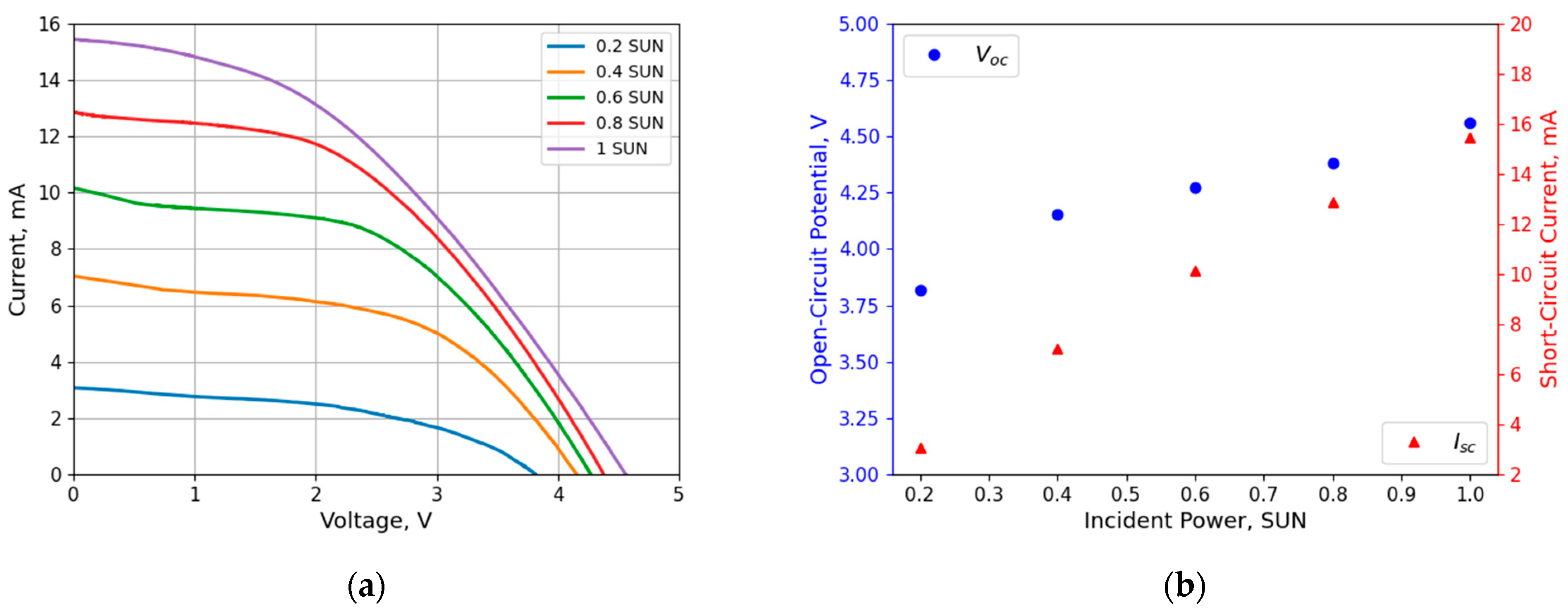
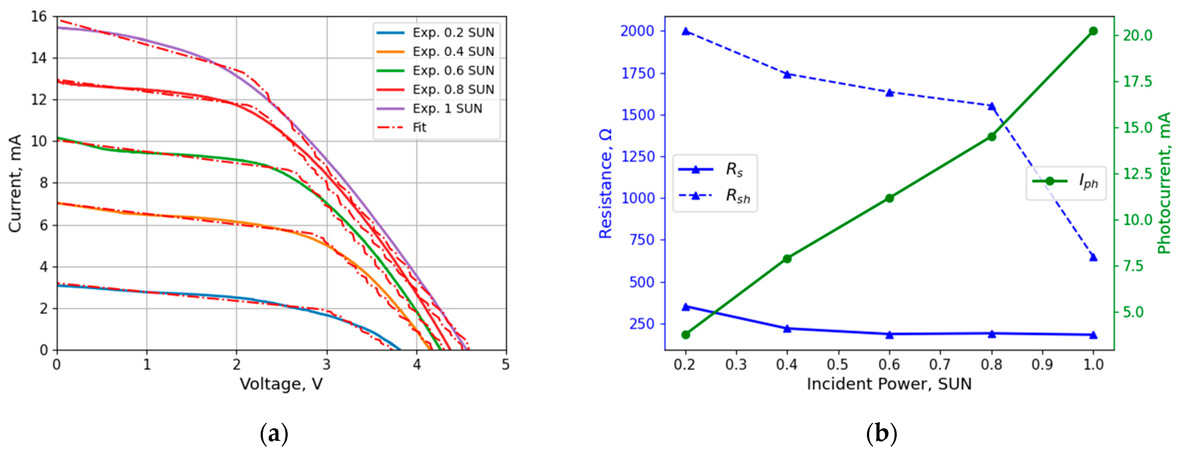
3.1. PV Characteristics

The DSSC module, consisting of six individual cells connected in series using conductive silver paste, was characterized under varying irradiance levels, as shown in Figure 2.
In Figure 2a, the I–V characteristics of the DSSC module vary according to the light intensity: in accordance with literature [23], the curve shifts to higher current–voltage regions with an increasing SUN of intensity.
In particular, it can be noticed that both the short-circuit current and the open-circuit voltage increase with respect to the light intensity applied (Figure 2b) due to the higher photogeneration of carriers [24]. In particular, the open-circuit voltage in DSSCs is influenced by the potential difference between the dye’s excited state and the conduction band of the TiO2 and the electrolyte. When light intensity increases, more photons are absorbed by the dye, which leads to the generation of more excited electrons in the dye. This increases the amount of charge transfer to the semiconductor, which strengthens the electric field across the junction between the semiconductor and the electrolyte. A higher number of photo-excited electrons in the dye enhances the electrochemical potential difference between the dye and the electrolyte, which, in turn, increases the open-circuit voltage. Regarding the short-circuit current, it is directly related to the number of electrons injected into the conduction band of the semiconductor after the dye is excited by the absorbed photons, thus increasing with the increased number of electrons photogenerated.
The experimental I–V characteristics (Figure 2a) are then fitted to extract the parameters for Equation (1) (Figure 3a,b), ensuring an accurate representation of the module’s electrical performance.
The I–V curves demonstrated the relationship between the incident power and the module’s performance, highlighting the effects of the changes in both series and shunt resistances with the increasing light intensity, similar to the results already present in the literature [19,20]. Rsh and Iph show a decrease/increase with respect to the incident power, respectively, while Rs remains constant. The shunt resistance is mainly connected to the recombination of photogenerated electrons from the photoanode to the electrolyte redox mediator. A reduction in the Rsh at lower light intensities is consistent with a decreased amount of photogenerated carriers in the TiO2, which are, therefore, extracted more efficiently from the photoanode and contribute to the external current. During the experimental conditions, a slightly lower temperature reached by the solar module at lower light intensities can also contribute to the reduction in the recombination reaction, resulting, therefore, in a lower shunt resistance. The series resistance, instead, arises mainly from geometric factors, electrical connections between the single DSSCs, and material properties, which are not dependent on the incident power.
The diode equation (Equation (3)), filled with the fitted parameters, was subsequently used as an electrical source within the COMSOL® simulation framework. This incorporation allowed the model to predict the operational conditions of the integrated PV–EC system under real-world scenarios. In the simulation, the PV module provided the necessary voltage and current for the electrochemical cell, enabling the evaluation of system performance at the intersection of the PV and EC module characteristics.

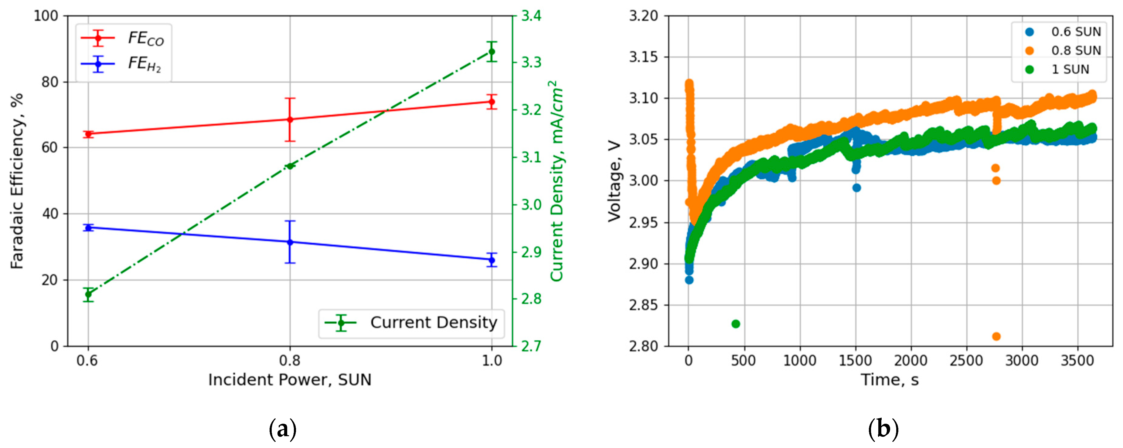
3.2. PV–EC Integration

Regarding the EC device, the performance (in terms of the FE, current density, etc.) has already been characterized and reported in the previous paper and summarized in the Supporting Information (Figures S1 and S2). For what concerns the PV–EC system, the first important step to thoroughly engineer the device is to establish the electrical operational point. Without any external imposed stimulation, the system finds its own operational point on the superimposition between the I–V characteristics of the PV and EC modules. In this case, as shown in Figure 4, the system should work at a Vop = 3.1V and a Iop = 8.6 mA, which corresponds to approximately 3.4 mA cm−2, when illuminated with an incident power of 1 sun. This self-adjusting behavior, where the system balances the I–V characteristics of both the PV and EC modules, ensures efficient operation without external control, emphasizing the robustness of the device in varying environmental conditions. In previous works, Cheng et al. [25] exploited Ag nanoparticles in a flow cell configuration, which, coupled with a GaInP/GaInAs/Ge triple-junction solar cell, showed a Jop = 13.8 mA cm−2 at Vop = 2.23V. Thanks to the gas diffusion electrode, in fact, it is possible to reach higher current densities, but the system will be limited by the solar cell’s ability to provide sufficient electrical energy. With large active areas, on the other hand, it is possible to exploit the systems for higher production rates, demonstrating the scalability of these PV–EC systems. As an example, Sriramagiri et al. [26] exploited Ag, as well, in a flow cell electrolyzer, with an active area of 25 cm2, coupled with five Si-based solar cells of a total area A = 125 cm2: they achieved a FECO = 75.9%, at Jop = 36.1 mA cm−2 at Vop = 2.71V, which means a Iop = 0.9A.
In Figure 5, the solar-driven electrochemical CO2 reduction is performed to produce CO through solar energy. Not only does the device show the correct operational point at 1 sun of illumination, but it is also possible to understand the performance under different conditions. At lower light intensities, in fact, the current density decreases rapidly (Figure 5a) along with the selectivity toward the CO2RR. Interestingly, the overall voltage (Figure 5b) does not change, ranging from 3.05 V up to 3.10 V when using 0.6 and 1 sun, respectively. This trend could be related to the proximity of the operational point with respect to the maximum power point of the solar cells, where the potential variation is small. As the device operates close to the MPP, the voltage remains nearly constant, even with changes in the light intensity, indicating that the PV module is effectively maintaining its voltage output within a narrow range.
The decrease in faradaic efficiency at lower light intensities, as observed in Figure 5a, suggests that the reduction in available energy leads to less efficient CO2 reduction. A lower light intensity, in fact, results in reduced electron flow, thus lowering the overall efficiency of the electrochemical reduction process. Since no liquid-phase products were detected in the catholyte during these analyses, only the faradaic efficiencies related to H2 and CO are reported. Lastly, the mathematical model was validated through the experimental result, as shown in Figure 6. By exploiting a time-dependent simulation, it has been possible to simulate a chronoamperometry of the PV–EC device with 1 sun illumination. Even though the model could not replicate the time length of the transient, and despite the experimental noise, the current density curve converged to 3.45 mA/cm2, which matches the experimental one with a 3% error. The mismatch in transient response observed between the experimental and simulated chronoamperometry data is likely a combination of model simplifications, experimental noise, and real-world complexities such as charge-transfer dynamics and system delays. For instance, the transient phase in electrochemical systems is often influenced by the rate of charge transfer and the diffusion of ions in the electrolyte. These processes can introduce delays or shifts in the current density curve, especially when the system is transitioning from one state to another. The model may not fully account for the complex interplay between these factors, such as the time required for the electrochemical reaction to stabilize or the time constant associated with ion diffusion.

4. Conclusions and Practical Recommendations

A PV–EC system, consisting of a module of DSSCs and a batch cell reactor with Ag nanoparticles as cathodic electrocatalysts, is presented. The device can efficiently convert CO2 to CO with no external energy input other than sunlight, and its performance has also been demonstrated in dimmer light conditions for outdoor applications in different weather conditions. In particular, a FE = 73.85% was achieved for CO production with a current density J = 3.35 mA/cm2 at 1 sun of illumination, while FE = 68.5% and FE = 64.1% were achieved with 0.8 and 0.6 suns, respectively. A complete model has been developed, as well, for the whole PV–EC device, demonstrating good agreement when reproducing the experimental data. The present work paves the way for real weather conditions for PV–EC devices, along with the development of more complex models for the solar-driven CO2RR. For instance, this work shows quantitative data that can be exploited to address the lower performance of the CO2RR at a lower incident power, which can be helpful in engineering the device in out-of-laboratory conditions.
Since Ag nanoparticles are a well-established catalyst that can reach higher current densities in the CO2RR [27], the limited current densities achieved with the batch cell reactor can be improved by exploiting different reactors, like zero-gap reactors. Nevertheless, in the PV–EC field, higher current density requirements must be fulfilled by bigger PV systems. For this purpose, the feasibility of the device demonstrated by the experimental data, combined with a suitable modeling approach to support the system’s scaling-up process, makes this work valuable for advancing integrated systems like the artificial leaf towards increasingly higher operating electrical points.

Supplementary Materials

The following supporting information can be downloaded at: https://www.mdpi.com/article/10.3390/app15020549/s1, Figure S1: Faradaic efficiency as a function of the voltage applied in a 2-electrode configuration; Figure S2: Current density as a function of the voltage applied in a 2-electrode configuration. Table S1: Kinetic parameters for electrochemical reactions.

Author Contributions

M.A.: Writing—review and editing, Writing—original draft, Investigation, Methodology, Data curation, Validation, Conceptualization. R.S.: Methodology, Writing—review and editing. A.L.: Resources, Writing—review & editing. C.F.P.: Project administration, Resources, Writing—review and editing. A.S.: Conceptualization, Data curation, Methodology, Supervision, Writing—review and editing. All authors have read and agreed to the published version of the manuscript.

Funding

This research was funded by the Italian Ministry of Education (MUR): the Ph.D. fellowship was funded under the National Research and Innovation Operational Program 2014-2020 (CCI 2014IT16M2OP005), ESF REACT-EU resources, Action IV.4 “Doctorates and research contracts on innovation topics”, and Action IV.5 “Doctorates on Green topics”. The project “Network 4 Energy Sustainable Transition—NEST”, Spoke 4, Project code PE0000021 was funded under the National Recovery and Resilience Plan (NRRP), Mission 4, Component 2, Investment 1.3—Call for tender No. 1561 of 11.10.2022 of Ministero dell’Universita’ e della Ricerca (MUR); funded by the European Union—NextGenerationEU. With the support of the ’Fondazione Compagnia di San Paolo’, as part of the VEIColo—Line 1 grant program. the project “nuovi Concetti, mAteriali e tecnologie per l’iNtegrazione del fotoVoltAico negli edifici e in uno scenario di generazione diffuSa” (“CANVAS”) was funded by the Italian Ministry of the Environment and the Energy Security, through the Research Fund for the Italian Electrical System (type-A call, published on G.U.R.I. n. 192 on 18-08-2022). This article was also partially funded under the National Recovery and Resilience Plan (NRRP), Mission 4, “Education and Research”, Component 2, “From research to business”, Investment 3.1, “Fund for the realization of an integrated system of research and innovation infrastructures”—Call for tender No. n. 3264 of 28/12/2021 by the Italian Ministry of Research, funded by the European Union NextGenerationEU, Project code: IR0000027, Concession Decree No. 128 of 21/06/2022, adopted by the Italian Ministry of Research, CUP: B33C22000710006, Project title: iENTRANCE. Technologies for Sustainability Flagship of the Istituto Italiano di Tecnologia.

Data Availability Statement

The raw data supporting the conclusions of this article will be made available by the authors upon request.

Conflicts of Interest

The authors declare no conflicts of interest.

References

  1. Overa, S.; Ko, B.H.; Zhao, Y.; Jiao, F. Electrochemical Approaches for CO2 Conversion to Chemicals: A Journey toward Practical Applications. Acc. Chem. Res. 2022, 55, 638–648. [Google Scholar] [CrossRef]
  2. Lin, R.; Guo, J.; Li, X.; Patel, P.; Seifitokaldani, A. Electrochemical Reactors for CO2 Conversion. Catalysts 2020, 10, 473. [Google Scholar] [CrossRef]
  3. Agliuzza, M.; Mezza, A.; Sacco, A. Solar-driven integrated carbon capture and utilization: Coupling CO2 electroreduction toward CO with capture or photovoltaic systems. Appl. Energy 2023, 334, 120649. [Google Scholar] [CrossRef]
  4. Creissen, C.E.; Fontecave, M. Solar-Driven Electrochemical CO2 Reduction with Heterogeneous Catalysts. Adv. Energy Mater. 2021, 11, 2002652. [Google Scholar] [CrossRef]
  5. Gurudayal; Bullock, J.; Srankó, D.F.; Towle, C.M.; Lum, Y.; Hettick, M.; Scott, M.C.; Javey, A.; Ager, J. Efficient solar-driven electrochemical CO2 reduction to hydrocarbons and oxygenates. Energy Environ. Sci. 2017, 10, 2222–2230. [Google Scholar]
  6. Kim, J.; Jeong, S.; Beak, M.; Park, J.; Kwon, K. Performance of photovoltaic-driven electrochemical cell systems for CO2 reduction. Chem. Eng. J. 2022, 428, 130259. [Google Scholar] [CrossRef]
  7. Abdelkareem, M.A.; Abdelghafar, A.A.; Mahmoud, M.; Sayed, E.T.; Mahmoud, M.S.; Alami, A.H.; Agha, M.M.A.; Olabi, A.G. Optimized solar photovoltaic-powered green hydrogen: Current status, recent advancements, and barriers. Sol. Energy 2023, 265, 112072. [Google Scholar] [CrossRef]
  8. Chatterjee, P.; Ambati, M.S.K.; Chakraborty, A.K.; Chakrabortty, S.; Biring, S.; Ramakrishna, S.; Wong, T.K.S.; Kumar, A.; Lawaniya, R.; Dalapati, G.K. Photovoltaic/photo-electrocatalysis integration for green hydrogen: A review. Energy Convers. Manag. 2022, 261, 115648. [Google Scholar] [CrossRef]
  9. He, H.; Zhang, Q.; Wang, Z.; Pan, S.; Zhao, Y.; Zhang, X. Advances and Practical Prospects for Bias-Free Photovoltaic-Driven Electrochemical Water Splitting Systems. Adv. Energy Mater. 2024, 14, 2303713. [Google Scholar] [CrossRef]
  10. Sacco, A.; Speranza, R.; Savino, U.; Zeng, J.; Farkhondehfal, M.A.; Lamberti, A.; Chiodoni, A.; Pirri, C.F. An Integrated Device for the Solar-Driven Electrochemical Conversion of CO2 to CO. ACS Sustain. Chem. Eng. 2020, 8, 7563–7568. [Google Scholar] [CrossRef]
  11. Wang, C.; Ren, H.; Wang, Z.; Guan, Q.; Liu, Y.; Li, W. A promising single-atom Co-N-C catalyst for efficient CO2 electroreduction and high-current solar conversion of CO2 to CO. Appl. Catal. B Environ. 2022, 304, 120958. [Google Scholar] [CrossRef]
  12. Zhang, W.; Xia, Y.; Chen, S.; Hu, Y.; Yang, S.; Tie, Z.; Jin, Z. Single-Atom Metal Anchored Zr6-Cluster-Porphyrin Framework Hollow Nanocapsules with Ultrahigh Active-Center Density for Electrocatalytic CO2 Reduction. Nano Lett. 2022, 22, 3340–3348. [Google Scholar] [CrossRef]
  13. Lee, W.H.; Lim, C.; Ban, E.; Bae, S.; Ko, J.; Lee, H.-S.; Min, B.K.; Lee, K.-Y.; Yu, J.S.; Oh, H.-S. W@Ag dendrites as efficient and durable electrocatalyst for solar-to-CO conversion using scalable photovoltaic-electrochemical system. Appl. Catal. B Environ. 2021, 297, 120427. [Google Scholar] [CrossRef]
  14. Gupta, N.; Gattrell, M.; MacDougall, B. Calculation for the cathode surface concentrations in the electrochemical reduction of CO2 in KHCO3 solutions. J. Appl. Electrochem. 2006, 36, 161–172. [Google Scholar] [CrossRef]
  15. Burdyny, T.; Graham, P.J.; Pang, Y.; Dinh, C.-T.; Liu, M.; Sargent, E.H.; Sinton, D. Nanomorphology-Enhanced Gas-Evolution Intensifies CO2 Reduction Electrochemistry. ACS Sustain. Chem. Eng. 2017, 5, 4031–4040. [Google Scholar] [CrossRef]
  16. Kotb, Y.; Fateen, S.-E.K.; Albo, J.; Ismail, I. Modeling of a Microfluidic Electrochemical Cell for the Electro-Reduction of CO2 to CH3OH. J. Electrochem. Soc. 2017, 164, E391. [Google Scholar] [CrossRef]
  17. Wu, K.; Birgersson, E.; Kim, B.; Kenis, P.J.A.; Karimi, I.A. Modeling and Experimental Validation of Electrochemical Reduction of CO2 to CO in a Microfluidic Cell. J. Electrochem. Soc. 2015, 162, F23. [Google Scholar] [CrossRef]
  18. Bader, S.; Ma, X.; Oelmann, B. One-diode photovoltaic model parameters at indoor illumination levels—A comparison. Sol. Energy 2019, 180, 707–716. [Google Scholar] [CrossRef]
  19. Chegaar, M.; Hamzaoui, A.; Namoda, A.; Petit, P.; Aillerie, M.; Herguth, A. Effect of Illumination Intensity on Solar Cells Parameters. Energy Procedia 2013, 36, 722–729. [Google Scholar] [CrossRef]
  20. Kassis, A.; Saad, M. Analysis of multi-crystalline silicon solar cells at low illumination levels using a modified two-diode model. Sol. Energy Mater. Sol. Cells 2010, 94, 2108–2112. [Google Scholar] [CrossRef]
  21. Agliuzza, M.; Pirri, C.F.; Sacco, A. A comprehensive modeling for the CO2 electroreduction to CO. J. Phys. Energy 2024, 6, 015004. [Google Scholar] [CrossRef]
  22. Goss, B.; Cole, I.R.; Koubli, E.; Palmer, D.; Betts, T.R.; Gottschalg, R. 4—Modelling and prediction of PV module energy yield. In The Performance of Photovoltaic (PV) Systems; Pearsall, N., Ed.; Woodhead Publishing: Sawston, UK, 2017; pp. 103–132. [Google Scholar]
  23. Zaky, A.A.; Sergeant, P.; Stathatos, E.; Falaras, P.; Ibrahim, M.N. Employing Dye-Sensitized Solar Arrays and Synchronous Reluctance Motors to Improve the Total Cost and Energy Efficiency of Solar Water-Pumping Systems. Machines 2022, 10, 882. [Google Scholar] [CrossRef]
  24. Guo, X.-Z.; Luo, Y.-H.; Li, C.-H.; Qin, D.; Li, D.-M.; Meng, Q.-B. Can the incident photo-to-electron conversion efficiency be used to calculate short-circuit current density of dye-sensitized solar cells. Curr. Appl. Phys. 2012, 12, e54–e58. [Google Scholar] [CrossRef]
  25. Cheng, W.-H.; Richter, M.H.; Sullivan, I.; Larson, D.M.; Xiang, C.; Brunschwig, B.S.; Atwater, H.A. CO2 Reduction to CO with 19% Efficiency in a Solar-Driven Gas Diffusion Electrode Flow Cell under Outdoor Solar Illumination. ACS Energy Lett. 2020, 5, 470–476. [Google Scholar] [CrossRef]
  26. Sriramagiri, G.M.; Ahmed, N.; Luc, W.; Dobson, K.D.; Hegedus, S.S.; Jiao, F. Toward a Practical Solar-Driven CO2 Flow Cell Electrolyzer: Design and Optimization. ACS Sustain. Chem. Eng. 2017, 5, 10959–10966. [Google Scholar] [CrossRef]
  27. Monti, N.B.D.; Fontana, M.; Sacco, A.; Chiodoni, A.; Lamberti, A.; Pirri, C.F.; Zeng, J. Facile Fabrication of Ag Electrodes for CO2-to-CO Conversion with Near-Unity Selectivity and High Mass Activity. ACS Appl. Energy Mater. 2022, 5, 14779–14788. [Google Scholar] [CrossRef]
Figure 1. Schematic representation of the electrochemical test: two peristaltic pumps are used for electrolyte recirculation, and the catholyte reservoir is sealed and connected to the gas chromatograph for product analysis (reprinted with permissions under the Creative Commons Attribution (CCA) 4.0 from [21]) (a); sketch of integrated PV–EC device (b).
Applsci 15 00549 g001
Figure 2. I–V curves of the dye-sensitized solar cells (DSSC) module (a) and open-circuit potential (short-circuit current) (b) at different light intensities.
Applsci 15 00549 g002
Figure 3. Fit of the I–V characteristics (a) and the incident power dependencies of Rs, Rsh, and Iph (b).
Applsci 15 00549 g003
Figure 4. Superimposition of the experimental photovoltaic (PV) cells and electrochemical cells (EC) characteristics, along with the IV curve retrieved by the mathematical model, at a light intensity of 1 SUN.
Applsci 15 00549 g004
Figure 5. Current density and faradaic efficiency of the PV–EC device (a) and overall cell voltage (b) as a function of the incident power.
Applsci 15 00549 g005
Figure 6. Experimental (a) and simulated (b) chronoamperometry of the PV–EC device under 1 SUN illumination.
Applsci 15 00549 g006
Disclaimer/Publisher’s Note: The statements, opinions and data contained in all publications are solely those of the individual author(s) and contributor(s) and not of MDPI and/or the editor(s). MDPI and/or the editor(s) disclaim responsibility for any injury to people or property resulting from any ideas, methods, instructions or products referred to in the content.

