Article

On the Stability of Graphene-Based Aqueous Dispersions and Their Performance in Cement Mortar

by
Teresa Gerace
1,
Sebastiano Candamano
2,*,
Simone Bartucci
1,
Carlo Poselle Bonaventura
1,
Alfonso Policicchio
1,
Raffaele Giuseppe Agostino
1,
Milena Marroccoli
3,
Antonio Telesca
3,
Mariano Davoli
4,
Andrea Scarcello
1,
Lorenzo S. Caputi
1 and
Daniela Pacilè
1
1
Department of Physics, University of Calabria, Via P. Bucci, 87036 Rende, Italy
2
Department of Mechanical, Energy and Management Engineering—DIMEG, University of Calabria, 87036 Rende, Italy
3
Scuola di Ingegneria, Università degli Studi della Basilicata, Via dell’Ateneo Lucano 10, 85100 Potenza, Italy
4
Department of Biology, Ecology and Earth Sciences—DiBEST, University of Calabria, 87036 Rende, Italy
*
Author to whom correspondence should be addressed.
Appl. Sci. 2025, 15(2), 835; https://doi.org/10.3390/app15020835
Submission received: 9 December 2024 / Revised: 13 January 2025 / Accepted: 14 January 2025 / Published: 16 January 2025

Abstract

:
Cement composites containing different carbon nanomaterials, namely graphene technical grade, graphene super grade, and graphene oxide, up to 1.0% by weight of cement, were prepared. Ultrasonic, chemical, and thermochemical treatments were applied to improve the stability of the dispersions containing the graphene-based nanomaterials. Their exfoliation was analyzed using Raman spectroscopy, and the stability of the dispersions was quantitatively investigated by means of the static multiple light scattering (SMLS) technique. The sonication process enhanced the intensity of the 2D band of graphene technical grade, suggesting a partial degree of exfoliation, while the hydrothermal treatment with sodium cholate significantly promoted the stability of its dispersion. The effect of the addition of selected graphene-based nanomaterials in mortars was evaluated in terms of fresh state properties, mechanical strength, capillary water absorption, and pore size distribution. Workability decreased with the increase in the amount of carbon nanomaterials. Field emission scanning electron microscopy (FESEM) was also employed to characterize the microstructure of pristine graphene-based nanomaterials and their inclusion within the cement matrix. Our results suggest that mechanical properties are only moderately affected by the inclusion of all additives, whereas the introduction of graphene significantly influences the coefficient of capillary water absorption. Specifically, a reduction of about 20% in the capillary water absorption coefficient was observed at the concentration of 1.0 wt% of graphene technical grade, which is ascribed to a refinement of the porosity.

1. Introduction

Incorporating carbon nanomaterials in cementitious composites is currently receiving increasing scientific interest [1,2,3]. The addition of carbon nanomaterials can enhance the durability and structural properties of cementitious composites and provide them with multifunctionality [4,5,6,7,8,9,10,11,12,13]. The influence of adding different carbon nanomaterials has been investigated in recent literature. One-dimensional (1D) nanomaterials, such as carbon nanofibers and carbon nanotubes, can contribute to the toughness and tensile strength of mortars and concrete through crack-bridging. However, they are characterised by a limited surface area that inhibits the nucleation of calcium silicate hydrated (C–S–H) gel on them, thus negatively affecting their strength [14]. Two-dimensional (2D) carbon nanomaterials, such as graphene (Gr) and graphene oxide (GO), are characterised by a large specific surface area (SSA) [6,15,16], high mechanical properties [6,17,18], excellent thermal conductivity [19], and high electron mobility [20,21,22]. They can provide both nucleation sites and a bridging effect. Based on these peculiar properties, Gr and GO have been used to produce reinforced, self-sensing, and thermally conductive concrete [22,23]. The incorporation of Gr or GO has primarily been employed to improve the mechanical properties (such as compressive strength and flexural strength) of cementitious materials, yielding varied and often not uniform results in terms of efficiency [6,18,24]. Several studies reported an increase of mechanical properties of cementitious materials by adding up to 0.1 wt% of Gr or GO [25,26]. A higher amount of Gr and GO have been used to provide cement-based composites with electrical and thermal properties, but a decrease in mechanical strength was observed, most likely due to the agglomeration of carbon nanomaterials generated by non-homogeneous dispersion of graphene nanoplatelets (GNPs) [27,28].
It is well known that treatments are necessary to improve the homogeneous dispersion of graphene nanomaterials and to promote their stability and exfoliation. The liquid phase exfoliation (LPE) of different carbon nanomaterials does not occur spontaneously in unsuitable solvents such as water, where the material–solvent interactions do not overcome the interlayer van der Waals attractive forces as well as the π π interactions to form stable dispersions. Therefore, external energy is necessary to promote the exfoliation of the layers. Several energy sources have been proposed so far, such as ultrasonication, wet ball milling, and microfluidization [29]. Ultrasonication generates power shockwaves and produces normal and shear forces on successive layers of the materials [30]. Wet ball milling provides shear forces in the liquid medium and promotes the vertical expansion of the layers and exfoliation [31]. In micro-fluidization, high pressure is exerted on the fluid to cause exfoliation of the material layers [32]. However, re-aggregation of the carbon nanomaterials continuously occurs and competes with exfoliation due to significant interlayer binding energies. This reversible process can also be regulated by modifying the nature of surface–solvent interactions. It can be obtained by using selected surfactants that bind with the carbon nanomaterials through van der Waals interaction. A promising surfactant to be used is sodium cholate (SC) (tri-hydroxy salt) [24]. It is characterized by a four-ring steroid nucleus with two hydroxyl groups and a five-carbon side chain terminating in a carboxylic acid. SC belongs to the facial amphiphiles class, as the arrangement of hydrophobic and hydrophilic groups provides it with a planar polarity. The above-mentioned peculiarities allow SC to present distinct properties that differ significantly from ordinary aliphatic surfactants, as they are relatively bulky and rigid with a distinct behaviour with respect to self-association and molecular solubilization. SC molecules not only intercalate between graphene sheets, but their hydrophobic moieties interact with hydrophobic graphene sheets, stabilizing them. Furthermore, SC can hinder re-aggregation through van der Waals interactions and the repulsion of the like-charged hydrophilic head-groups of the surfactant bound to each of the nanosheets [33]. An interesting method to provide external energy for exfoliation is represented by hydrothermal treatment. It generates shear force by the Brownian motion of various molecules at high temperature and high pressure [34].
In recent scientific literature, two methods have been adopted to better evaluate the dispersibility and stability of graphene, the former being the visual observation method and the latter measuring the ultraviolet-visible absorbance at the intrinsic absorption peak of carbon nanomaterials [5,35,36,37]. Specifically, higher absorbency values correspond to better dispersion in water, with the absorbance directly proportional to the concentration, according to the Beer–Lambert law. However, the use of the ultraviolet-visible spectrophotometry (UV–vis) requires collecting the absorption spectra of graphene-based dispersions not only in terms of different concentrations but also distinguished for each amount of the specific dispersants used to obtain calibration curves. Moreover, as reported in different papers [37], the dispersants, by recombinating with carbon nanomaterials or interfering with their absorption curves, can affect the accuracy and reliability of analyses. Furthermore UV–vis spectrophotometers work by passing a beam of light through the sample and measuring the amount of light that is absorbed at each wavelength at a certain time, requiring the dilution of highly concentrated dispersion, which alters their state and structure. Static multiple light scattering (SMLS) offers the ability to investigate the dispersion state and its evolution over time in their native state, without any dilution, even on highly concentrated samples. The TURBISCAN technology, employing SMLS, measures transmission or backscatter intensities versus the sample’s height and ageing time. During the analysis, an infrared light source scans the sample vertically, while two sensors collect the transmitted (T) and backscattered (BS) light at different heights. The stability of the suspensions over time is tracked by the accurate and reliable Turbiscan Stability Index (TSI).
In this study, various graphene-based additives, namely graphene technical grade (Gr-TG), graphene super grade (Gr-SG), and GO, have been characterised and added at different percentage contents (0 ÷ 1% by weight of cement, a range that allows enhanced thermal and self-sensing performances [38]) to a reference mortar. Based on the reported scientific literature and given the hydrophobic nature of Gr-TG and Gr-SG, a two-step process was proposed and implemented to improve their exfoliation and prevent the layers from restacking. It was characterized by an initial hydrothermal treatment (HT), aided by the addition of surfactant SC, followed by ultrasonication. The dispersions containing GO were not subjected to the HT step, as it is dispersible in water, but only to ultrasonication. The stability of the dispersions with the highest concentration was quantitatively investigated by means of the static multiple light scattering (SMLS) technique. The effect of the type and amounts of graphene-based nanomaterials on the fresh and hardened properties of mortars was evaluated. Microstructures were analyzed through field emission scanning electron microscopy (FESEM) measurements. Nitrogen and mercury intrusion porosimetry (MIP) were employed to explore the porosity and assess capillary water absorption (CWA) results.

2. Materials and Methods

2.1. Materials

Ordinary Portland Cement (OPC—indicated as “c”) CEM II/A-LL 42.5 R (see Table 1), a natural siliceous sand (s) with gradation reported in Figure 1, and ViscoCrete®-5370 I, a polycarboxylate type superplasticizer (SP) purchased from Sika, were used to manufacture the mortars. Different types of carbon nanomaterials were used as dopant additives: Gr-TG, Gr-SG, and GO, all purchased from BT CORP Generique Nano (PVT.LTD) Private Limited. Their physical properties are listed in Table 1. The surfactant SC (C24H39NaO5), purchased from Thermo Scientific Alfa Aesar, was introduced in Gr-TG and Gr-SG based dispersions.

2.2. Exfoliation Pretreatment

Given the hydrophobic nature of Gr-TG and Gr-SG, a two-step process was proposed and implemented to improve their exfoliation and prevent the layers from restacking. It was characterized by an initial hydrothermal treatment (HT), aided by the addition of surfactant SC, followed by ultrasonication.
Water dispersions were prepared by mixing water, Gr-TG, or Gr-SG with surfactant SC. The prepared dispersions were initially mechanically stirred at 100 rpm for 5 min. The final graphene-based nanomaterial concentration was fixed at 1.53 wt% or 2.50 wt% on water. Surfactant SC to Gr-TG (or Gr-SG) mass ratio was fixed at 1/5. After stirring, each dispersion was poured into autoclaves (volume of 50 cm3) and heated at a rate of 1.5 °C/min up to the set point temperature, which was fixed at 180 °C, and kept at this temperature for 6 h. Finally, the dispersions were ultrasonicated in a SOLTEC-SONICA M S3 bath ultrasonicator (40 kHz, 80 W) for 6 h before being used in the production of mortars. In order to prevent overheating, the beakers were placed in a cold water bath during ultrasonication. The dispersions containing GO were prepared by mixing water and GO. The prepared dispersions were initially mechanically stirred at 100 rpm for 5 min. The final GO concentration was fixed equal to 1.53 wt% or 2.50 wt% in water. After stirring, GO dispersions were ultra-sonicated in a Soltec-Sonica M S3 bath ultrasonicator (40 kHz, 80 W) for 6 h before being used in the production of mortars. In order to prevent overheating, the beakers were placed in a cold water bath during ultrasonication. The composition of all the prepared graphene-based dispersions and operational details of each treatment are summarized in Table 2. Water dispersions with concentration equal to 1.53 wt% were then used to produce mortars containing up to 0.3 wt% of graphene-based nanomaterials. It worthy to be noted that it was necessary to use water dispersions with concentration equal to 2.50 wt% to produce mortars in the range of 0.5–1 wt% to comply with the fixed w/c ratio selected for the mix design (see Table 3).

2.3. Mix Design

Mix designs of all mortars produced during the experimental campaign are reported in Table 3, with the percentages of carbon nanomaterials reported by weight of cement. Preliminary investigation has allowed us to fix the proper SP/c ratio at 0.009 to guarantee adequate workability for most of the mortars functionalized with the carbon nanomaterials over the tested concentration range. Only mortars containing more than 0.3 wt% of Gr-SG required an amount of SP that exceeded the allowed limit provided by the manufacturer; therefore, they were not included in the experimental campaign. Mortar C, which does not contain any GPNs or GO, was used as a reference. All mortars were produced according to the UNI EN 196-1 standard, modified to take into account the addition of graphene-based dispersions and SP. Water containing the SP and the graphene-based dispersion was mixed with cement and stirred in a Hobart mixer at 140 ± 5 rpm for 30 s. The sand was then added and mixed for 30 s at 285 ± 10 rpm. After 30 s, the mechanical mixing was stopped for 90 s, and the mortar adhered to the container was hand-mixed; then the mixing continued at 285 ± 10 rpm for 120 s. Each mix was finally poured in two steps into steel prismatic formworks with dimension of 40 mm × 40 mm × 160 mm, vibrating after each step for 30 s to eliminate air bubbles. Finally, moulds were stored for 24 h in the climatic chamber at 20 °C and R.H. ≥ 90%. After that, mortar specimens were de-moulded and cured for 28 days in the climatic chamber under the same conditions.

2.4. FESEM and Raman Spectroscopy

In order to investigate the additives in terms of morphology and thickness, FESEM and Raman spectroscopy were employed before their inclusion in the cement mortar admixtures.
FESEM analyses were performed on pristine Gr-TG and GO, deposited on a carbon-based conductive double-sided tape with a FEI QUANTA 200F (FEI Co., Heindoven, The Netherlands). Raman spectroscopy was performed with a JASCO NRS-5100 (JASCO Corporation, Tokyo, Japan) Raman Spectrometer (532.11 nm, 0.6 W; single monochromator with a grating of 1800 L/mm; notch filter 532.0 nm; objective lens MPLFLN 100×; exposure time 10 s) on the additives shown in the following and for different typologies of dispersion.
Morphological and chemical characterisation was also carried out on doped cement mortar, 1TG, and 1GO specimens, through FESEM and Energy Dispersive X-ray (EDX), using an Ultra High Resolution SEM (UHR-SEM)—ZEISS CrossBeam 350 (ZEISS group, Jena, Germany). FESEM and EDX analyses were performed on cement mortar fragments sputtered with a thin conductive carbon layer to reduce charging effects.

2.5. Suspension Stability Characterisation

The suspension stability was studied by means of the SMLS technique, using a Turbiscan LAB® analyser (Microtrac Formulaction, Toulouse, France). This instrument analyses samples with a volume of about 30 mL. During the analysis, an infrared light source (wavelength λ = 880 nm) scans the sample vertically, while two sensors collect the transmitted (T) and backscattered (BS) light at different heights. By comparing these profiles, the Turbiscan LAB® can track changes in the sample over time and compute the Turbiscan Stability Index (TSI). The TSI (a dimensionless number) is calculated at time “t” by summing up all temporal and spatial fluctuations within a designated area:
T S I ( t ) = 1 N h t i = 1 t m a x z i = z m i n z m a x | B S T ( t i , z i ) B S T ( t i 1 , z i ) |
where N h = ( z m a x z m i n ) / Δ h is the number of height positions in the selected area; z m a x and z m i n are, respectively, the upper and lower selected height limits; t m a x is the last time t at which the TSI is calculated; B S T is the signal under consideration (its value is B S when T < 0.2 % and T otherwise).
Based on the TSI values, suspensions are classified into five categories, each corresponding to a different quality grade. (A+ The Turbiscan® detects no notable destabilisation, maintaining visual stability. An A+ ranking denotes the highest level of stability. A No visually apparent destabilization is detected at this early stage, either through migration or size variation. B The Turbiscan® detects higher variations indicating the beginning of destabilization, yet visual cues are largely absent (>90%); C Significant destabilization is evident, characterized by notable sedimentation, creaming, broad particle size shifts, or minor phase separation. Though not always visible, caution is advised, necessitating careful monitoring of samples in this category. D Severe and conspicuous destabilization is evident, likely observable through substantial sedimentation, creaming, phase separation, considerable particle size or colour changes, signalling a visual failure.)

2.6. Analysis of Workability

Fresh cement mortar workability was measured by using a Matest E090 KIT (Matest, Treviolo, Italy) hand-operated flow table, following UNI EN 1015-3:2007 [39]. After fifteen consecutive strokes, the resulting diameter of the specimen was measured. Subsequently, workability was calculated using Equation (2):
W = 100 d m d d
here, d m represents the average among measured diameters, and d denotes the bottom diameter of the flow mould.

2.7. Ultrasonic and Mechanical Tests

Ultrasonic measurements were performed with a Matest Ultrasonic meter Ver.02.00.001 (55 kHz) by following UNI EN 12504-4:2005 [40]. For each specimen, two measurements were acquired, with the physical quantity being the time (also known as time of flight—TOF) that ultrasonic pulses take to travel the geometric distance between the two probes. Through the measurement of time and consequently the velocity at which ultrasonic waves traverse the specimen, the elastic dynamic modulus, E d , was calculated using Equation (3).
E d = v 2 ρ ( 1 + ν d ) ( 1 2 ν d ) ( 1 ν d ) ,
where v is the velocity, ρ is the density of the specimen, and ν d is the Poisson’s ratio; for cement mortar, there is a scalar quantity of ∼0.2 [41].
Mechanical tests were carried out according to UNI EN 1015-11:2001 [42] by using an Instron-5582. The flexural strength of mortars was determined by three-point loading of prismatic specimens with dimensions of 4 cm × 4 cm × 16 cm. The compressive strength of the mortars was determined on the two parts resulting from the flexural strength test. By standard procedure, a deflection rate of 0.008 mm/s was chosen for flexural strength tests and 0.015 mm/s for compressive strength tests.

2.8. Capillary Water Absorption Test

CWA tests have been carried out using the gravimetric method, according to UNI EN 1015-18 [43]. The equation employed to model water absorption through capillary action is the following [44]:
A = a 0 + S t 1 2
where A (kg/m2) is the water absorption per unit area since the dipping in water; S (kg/(m2 min 1 / 2 )) is the sorptivity of the material; t is the elapsed time in minutes, and a 0 (kg/m2) is the water initially absorbed by pores in contact with water.

2.9. Nitrogen and Mercury Intrusion Porosimetry

Nitrogen porosimetric analysis was carried out using a Micromeritics ASAP 2460 apparatus (Micromeritics, Norcross, GA, USA). Before each measurement, all the specimens were subjected to a thermal treatment (degas procedure) under vacuum (p 10 × 10 6 mbar) at 100 °C for 24 h. The N 2 adsorption/desorption isotherms of each specimen were acquired at −196 °C up to 1 bar of pressure. Surfaces and porosity features were then evaluated from the experimental N 2 adsorption/desorption isotherms. In particular, the first was calculated according to the Brunner–Emmett–Teller model (BET) [45] within relative pressure range 0.05–0.3, while pore size distribution (PSD), cumulative, and pore volume (CPV) were evaluated by Barrett, Joyner, and Halenda (BJH) analysis using the Kelvin model of pore filling [46,47,48,49].
MIP was performed on a Thermo Finnigan Pascal 240 Series porosimeter (maximum pressure, 200 MPa) coupled with a low-pressure unit (140 Series) able to generate a high vacuum level (10 Pa) and operate between 100 and 400 kPa. During the test, with increasing pressure, mercury gradually penetrates the bulk sample volume. Moreover, as the MIP data do not provide any information on the pore size distribution in the sample, an appropriate model has to be used. In this regard, if a system of cylindrical pores is considered, the Washburn equation (Equation (5)) can be applied; it allows us to estimate the diameter of cylindrical pores intruded at each pressuring step, namely:
d = 4 γ cos θ P
where d is the diameter of the cylinder being intruded, γ is the surface tension of mercury, θ is the contact angle of mercury on the solid, and P is the applied pressure.

3. Results and Discussion

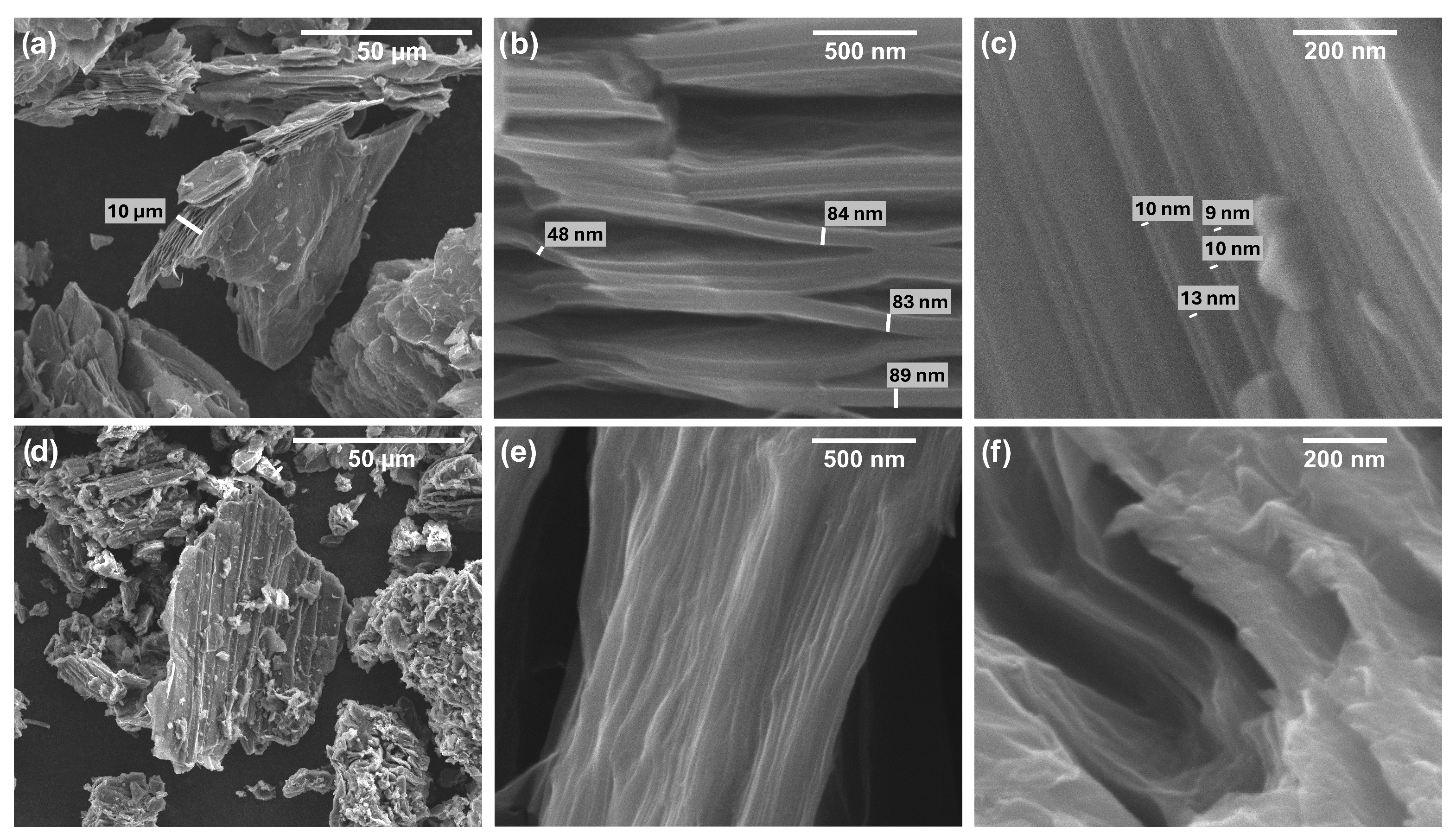
3.1. FESEM Measurements on Pristine Additives
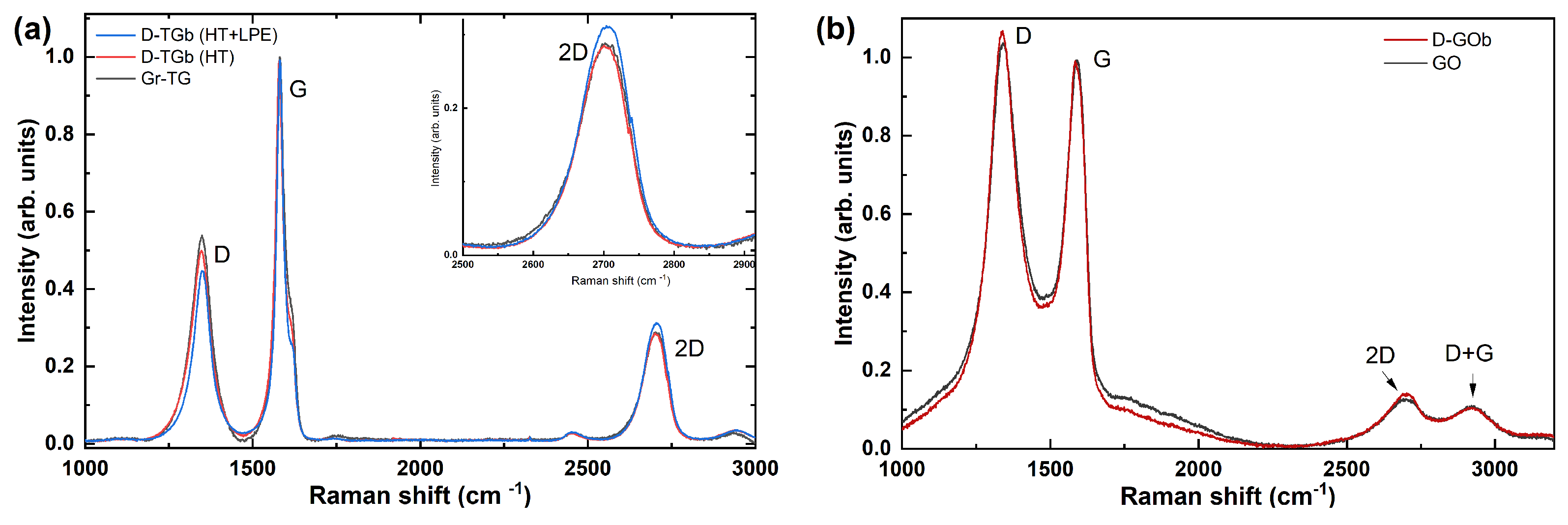
Representatives images of Gr-TG additives are shown in Figure 2a–c, allowing the average thickness to be observed within the relative scale. The results reveal that Gr-TG thick fragments exhibit a typical thickness above 10 µm (Figure 2a). Multilayers display values within the range of 40 to 90 nm (Figure 2b), while regions with few layers exhibit an average thickness of approximately 10 nm (Figure 2c). Taking into account the interplanar distance of 0.335 nm in graphite, the average thickness of thin fragments is approximately 30 layers, as reported in Table 1.
Representative images of GO fragments are shown in Figure 2d–f. The difference with respect to Gr-TG is clearly visible: first, image saturation (white regions of the fragments) was recorded due to the presence of oxygen groups, typical of the material, which caused the accumulation of surface charge; secondly, a less ordered, though still layered, structure is observed.

3.2. Raman Spectra

Graphene-based materials exhibit exceptional functional properties, making them an extremely promising nanoscale additive for enhancing the multifunctionality of concrete composites [22,23]. However, to preserve graphene’s full potential in cementitious materials, a significant challenge must be overcome: achieving uniform dispersion of the nanosheets without compromising their quality. This challenge remains a key research focus because graphene has an intrinsic tendency to agglomerate due to van der Waals interactions within planes, at the expense of the cement matrix mixture’s uniformity. Consequently, various mechanical mixing/agitation and chemical modification techniques have been developed to uniformly disperse graphene within the cementitious matrix, ensuring its nanoscale properties are fully utilised [3,50].
In the present work, to assess the quality of graphene additives and the effect of subsequent treatments, Raman spectra were systematically acquired. In Figure 3a, representative results are reported for: as-received Gr-TG (gray line); D-TGb (after HT), not sonicated dispersion (red line); and D-TGb after HT and LPE (blue line).
All the spectra reported in Figure 3a exhibit the G peak (1581 cm−1), which arises from a first-order process activated by an iTO or iLO phonon with q = 0 momentum and is typical of graphene-based materials. The 2D mode, typically centered at about 2700 cm−1, is associated with a second-order process involving two iTO phonons with opposite momenta at the border of the Brillouin zone and is linked to the breathing of the hexagonal mesh of graphene. The 2D band’s overall shape (located at 2703 cm−1 and with a full width at half maximum of (74.19 ± 0.98) cm−1 for Gr-TG) and the ratio relative to the G band, point to the conclusion that the utilized additive is turbostratic graphene [51,52]. In the same region of the spectrum, as highlighted in the inset of Figure 3a, the Gr-TG and the D-TGb (HT) completely overlap. On the other hand, after sonication, the D-TGb (HT+LPE) suspension shows an enhanced intensity of the 2D band of about 11%, suggesting a partial degree of exfoliation [53]. The existence of the D band (1349 cm−1), related to a second-order process, is pronounced in all the spectra and indicates the presence of planar and edge defects in the graphene sheets, while its intensity is related to the nanosheet size [53].
In Figure 3b, Raman spectra of as-received GO (gray) and D-GOb dispersion (red) after LPE, are shown. GO spectrum exhibits the D peak (1341 cm−1) intensity slightly higher than the G one (1588 cm−1) with a relative ID/IG ratio of 1.16, indicating that the material presents many defects due both to the defective and disordered surface, given by the high carbon/oxygen ratio (see Table 1) [54] and edges [55]. After sonication, slight changes are observed in the spectrum, including an ID/IG ratio increment of about 4%.

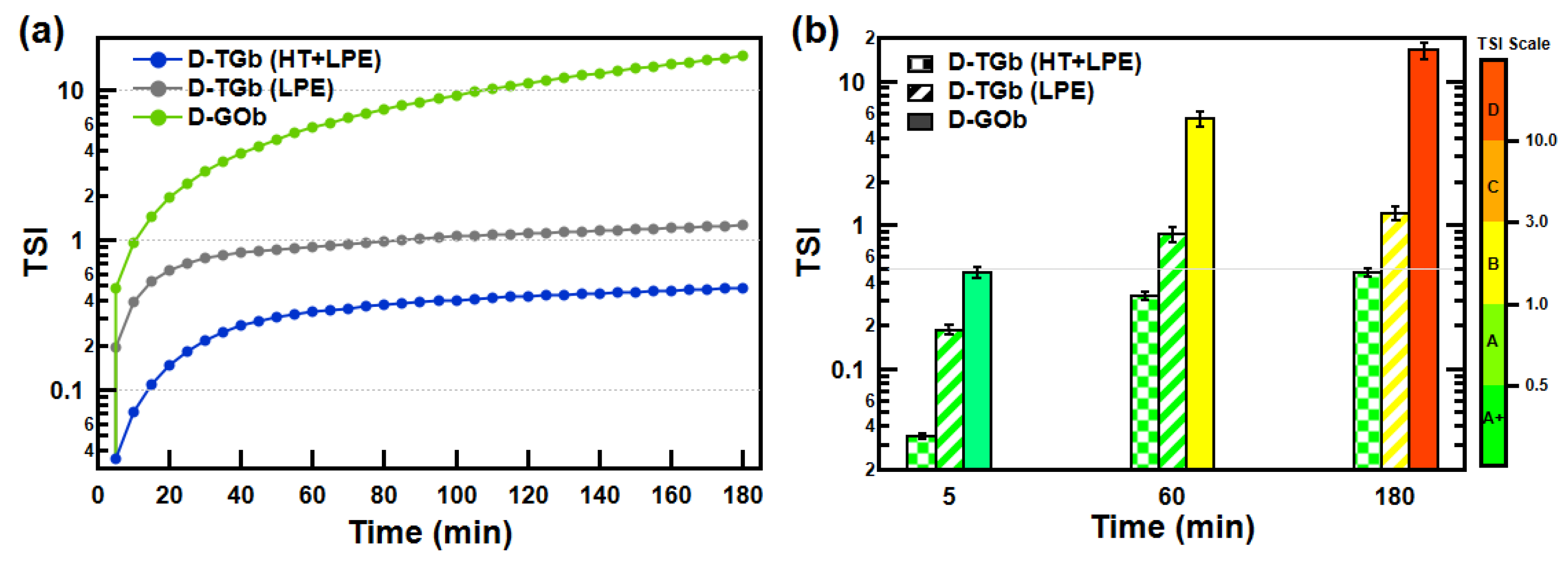
3.3. Suspension Stability Characterization

The Turbiscan Stability Index (TSI) was measured for the suspensions D-TGb and D-GOb of Table 2, as they are characterized by the highest concentration of carbon nanomaterials and thus represent the harshest condition for stability in the investigated range. Furthermore, in order to evaluate the impact of the HT treatment on suspension stability, a type D-TGb suspension, subjected to only LPE, was also prepared and used as a reference.
Measurements were taken every 5 min for a total time of 180 min. Following this procedure, a detailed description of each suspension is provided in Figure 4a,b, assessing its stability over time and assigning each suspension to its category.
It is to be noted that, within 3 h, while the D-TGb (LPE) sample undergoes from A+ to B suspension type (refer to the colour scale bar of Figure 4b), D-TGb (HT+LPE) remains A+ suspension. These results demonstrate that the HT treatment effectively promotes the dispersion of graphene in water and significantly enhances its stability. On the other hand, considering the stability of the D-GOb suspension within the first 5 min, all batches of cement mortar were prepared immediately after concluding the LPE treatment.

3.4. Workability Analysis

In Table 4, workability data taken for selected admixtures are reported. As expected, the increasing in the amount of graphene-based nanomaterials negatively affected the workability of the mortars [6,15,16].
However, it is worthy to note that workability is also significantly affected by the type of additive. Gr-SG showed a reduction of about 46% in workability even when 0.3 wt% was added. As expected, this is due to its higher SSA, as reported in Table 1. An increase in the amount of Gr-SG leads to an unworkable mortar, which is why the concentration of this additive was limited to 0.3 wt%. Mortars containing GO showed values of workability mildly affected by the addition of up to 0.5 wt% GO. This result can be attributed to poor exfoliation and dispersion of GO flakes, as only ultrasonic treatment was carried out on those suspensions. However, at the highest concentration of GO, the increased number of flakes, and therefore the hydrophilic surface, reduces the workability by about 40%.

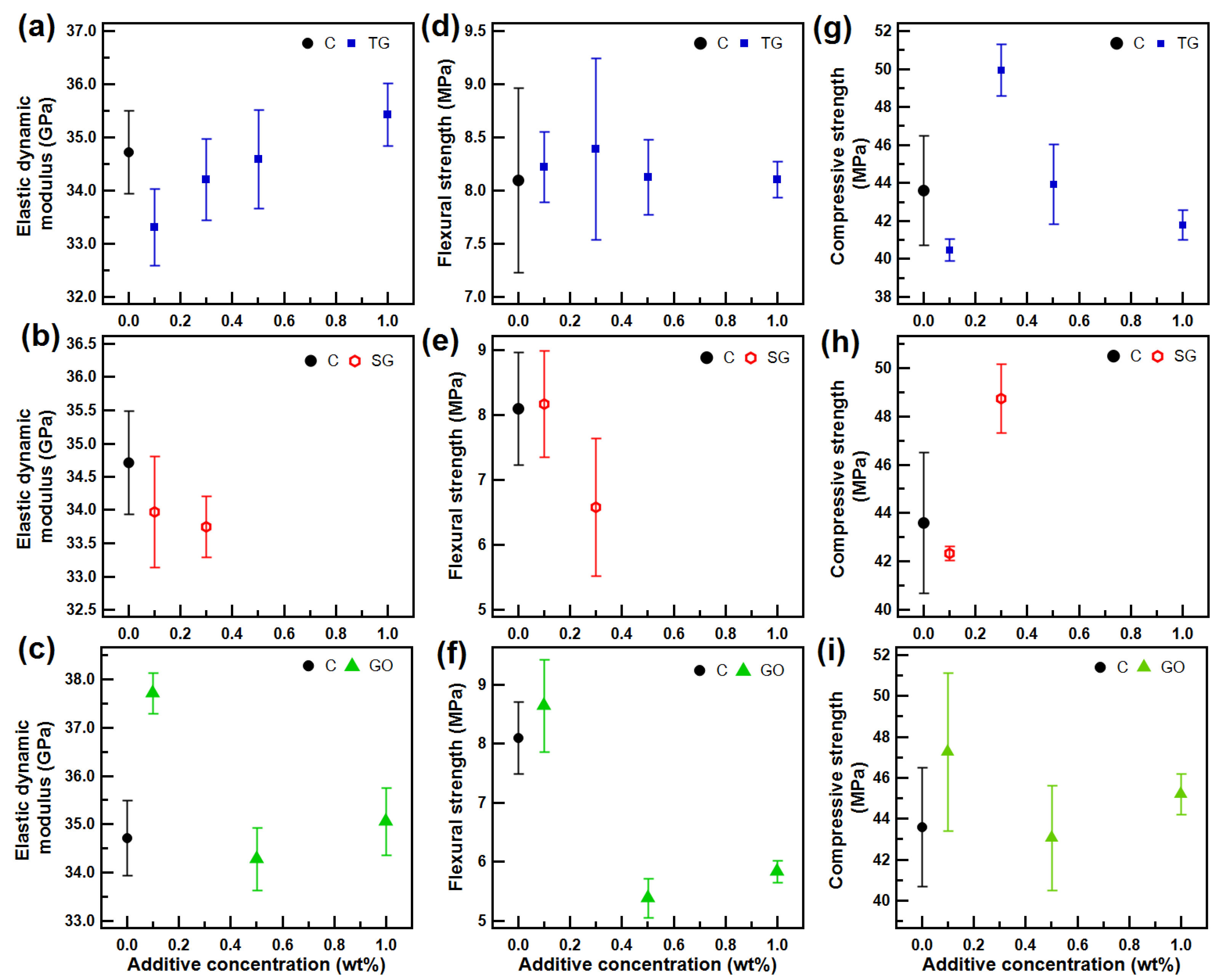
3.5. Ultrasonic and Mechanical Tests

In Figure 5a–c, the results of the ultrasonic test are shown. In the top panel, Gr-TG exhibits an increase in the E d values with rising concentration. This outcome suggests that the Gr-TG additive leads to a reduced porosity in the cement matrix, which might enhance strength. The trend for the other two additives is less distinct.
The flexural strength of the doped samples, shown in Figure 5d–f, is comparable to that of the reference mortar up to 0.1% by weight of cement of graphene-based nanomaterials. However, a different outcome can be observed at higher concentrations. Mortars doped with Gr-TG (upper panel) do not show a significant variation in the flexural strength, whereas the increase in the amount of Gr-SG (middle panel) and GO (lower panel) leads to a loss of 19% and 33%, respectively.
In Figure 5g–i, the compressive strengths of Gr-TG (upper panel), Gr-SG (middle panel), and GO (lower panel) are reported. The addition of 0.3 wt% of Gr-TG and Gr-SG increases the compressive strengths of mortars by 15% and 12%, respectively.
A further increase of graphene-based nanomaterials, within the investigated range, does not provide a beneficial effect on the compressive strength. Mortars doped with GO show a similar trend.
Overall, the results show that at lower concentrations of graphene-based nanomaterials, a slight improvement in compressive strength and a negligible effect on flexural strength are observed, regardless of the type of graphene-based nanomaterials used. The improvement can be ascribed to both nucleation and filling effects [5,35,56]. Graphene-based nanomaterials, when properly dispersed in the cementitious matrix and in adequate amounts, act as nucleation sites for C-S-H, thus improving the microstructure through densification of the hydration products. The results obtained under flexural tests can instead be explained by the fact that graphene-based nanomaterials, based on their dimensions and high aspect ratio, can only provide a strengthening effect in the cement paste but fail in transferring the stresses or bridging the microcracks that form in the interfacial transition zone (ITZ) or between sand particles, as they are only larger than the calcium silicate hydrate (C-S-H) particles [5]. At higher concentrations, a limited decline in mechanical properties is observed, regardless of the type of graphene-based nanomaterials used, as a result of their agglomeration that promotes a weakening of the cement matrix, as supported by FESEM analysis (see Section 4).

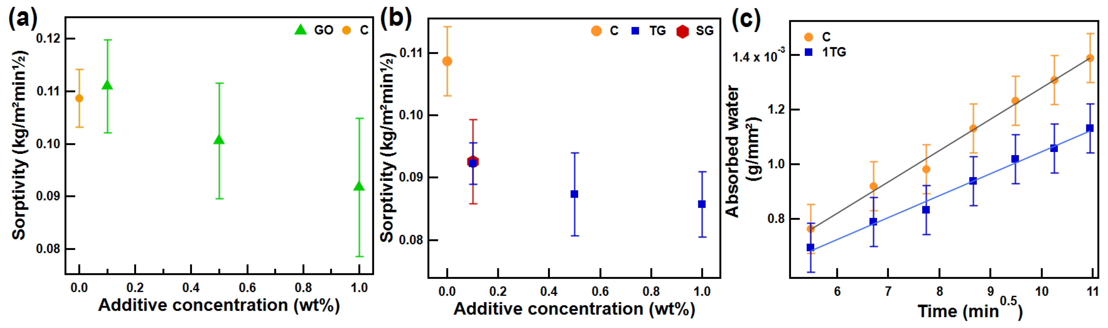
3.6. Capillary Water Absorption Test
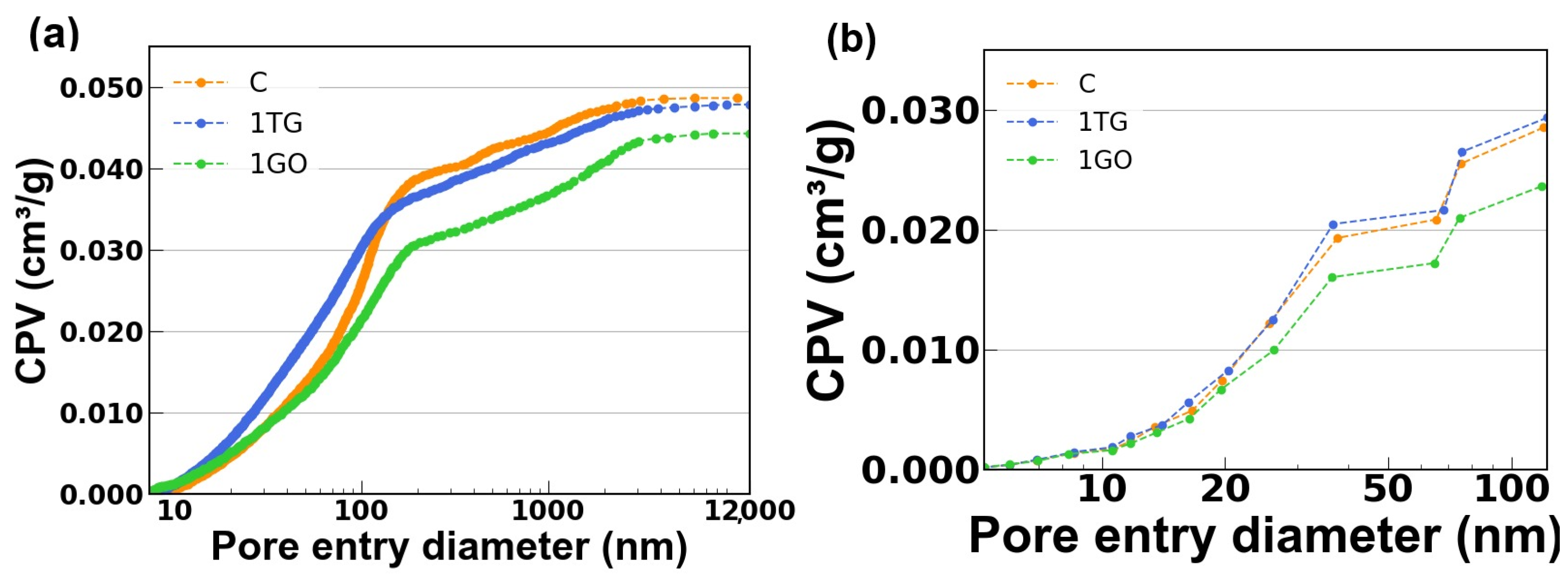
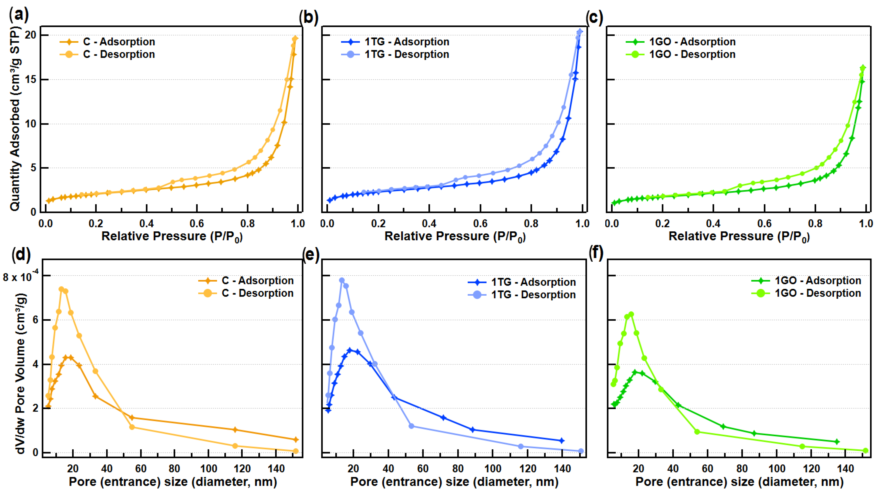
The results of sorptivity obtained for most of the prepared mortars in the range of doping 0.1–1.0 wt% are reported in Figure 6a,b (UNI EN 998-1). Notably, it was found that all doped specimens exhibit a reduction in the CWA coefficient as the concentration of the additive increases (Figure 6a,b). The maximum difference observed is about 20% for the 1TG specimen. This particular result is reported in Figure 6c for a set of primitive data taken on a representative 1TG and compared to C specimen.
Given that the phenomenon of water capillary rise is intricately related to the porous structure of materials [5,57,58], the trends observed in Figure 6a,b suggest that the incorporation of the additives alters the internal capillary network of pores in mortar specimens. Accordingly, the ultrasound test for Gr-TG reported in Figure 5a shows that as the concentration of graphene increases, the value of Ed, related to the material’s density, also rises.

3.7. Porosimetry

In order to explain the findings obtained by CWA, both MIP and N 2 adsorption/desorption isotherm analyses were carried out [59]. Cementitious materials are heterogeneous systems mainly characterized by mesopores and macropores. Based on the nature of pore formation, gel pores ( ρ 10 nm) and capillary pores (10 nm ρ 10 µm) can be distinguished [60]; in relation to the hazardousness of pores based on their size, Wu et al. [60] defined four ranges of pore sizes as: harmless ( ρ < 20 nm); less harmful (20 nm ρ 50 nm); harmful (50 nm ρ 200 nm); and multi-hazardous ( ρ > 200 nm). MIP is known to give information on pore sizes ranging from tens of micrometers down to a few nanometers (small mesopores), but it fails to access micropores ( ρ < 2 nm). Furthermore, previous studies have shown that this investigation technique can be potentially harmful to cementitious materials due to the high pressures applied, the need for a preliminary drying step, and the ink-bottle effect, which might alter its outcome [61,62,63]. On the other hand, N 2 porosimetry provides more detailed surface information when focusing on micropores ( ρ < 2 nm) and small mesopores (2 nm ρ 50 nm) [63,64]. Both techniques have access only to open pores. Considering the observations made above, results obtained from both methods were combined to study the PSD over the wide range [0–12,000] nm. The isotherms of N 2 adsorption and desorption of the investigated mortars are reported in Figure 7a–c. They can be classified as type IIb, as there is no indication of a plateau at high P / P 0 , with a H3 hysteresis loop. The narrow loop and the forced closure of the hysteresis loop near P / P 0 = 0.45 that characterize all the mortars suggest that some constrictions are present in these samples at the nanometric scale due to the presence of pore network effects, with interconnected larger pores emptying through pores with smaller diameters. The isotherms are the result of interparticle capillary condensation and indicate the presence, in the microstructure of the mortars, of aggregates of particles giving rise to slit-shaped pores that provide them with meso and macro-porosity. In order to further confirm the evidence, data from N 2 adsorption/desorption isotherms were analyzed using the Barrett–Joyner–Halenda (BJH) theory. Specifically, the pore size distribution (PSD) was determined using the adsorption branch and the pore entrance size distribution (PESD) using the desorption branch of the curve, based on the Harkins and Jura equation with Faas Correction [65].
The PSD and PESD for each mortar are shown in Figure 7d–f. The curves of PESD were corrected, taking into account the tensile strength effect produced by the forced closure of the hysteresis loop around P / P 0 = 0.45 [66]. All tested samples showed unimodal PSD and PESD distribution with peaks volume centred around 17.8 and 13.5 nm, respectively, indicating in all cases that pore entrance sizes were smaller than pore sizes in the investigated range. Cumulative pore volume (CPV) was thus obtained as a function of the pore entrance width by considering data obtained from N 2 adsorption isotherms for porosities below 50 nm and those obtained by MIP analysis for porosities above 50 nm up to 12,000 nm (see Figure A1 in Appendix A) [64].
The result of the combination is reported in Figure 8a, while the obtained pore volumes (PV) contribution per unit of mass in each pore size range is reported in Figure 8b. Figure 8b clearly shows that the addition of the selected graphene-based nanomaterials decreases the pore volume contribution per unit mass in the more harmful pore size range in the cement matrix. The results support and explain the outcome of the capillary water absorption tests.

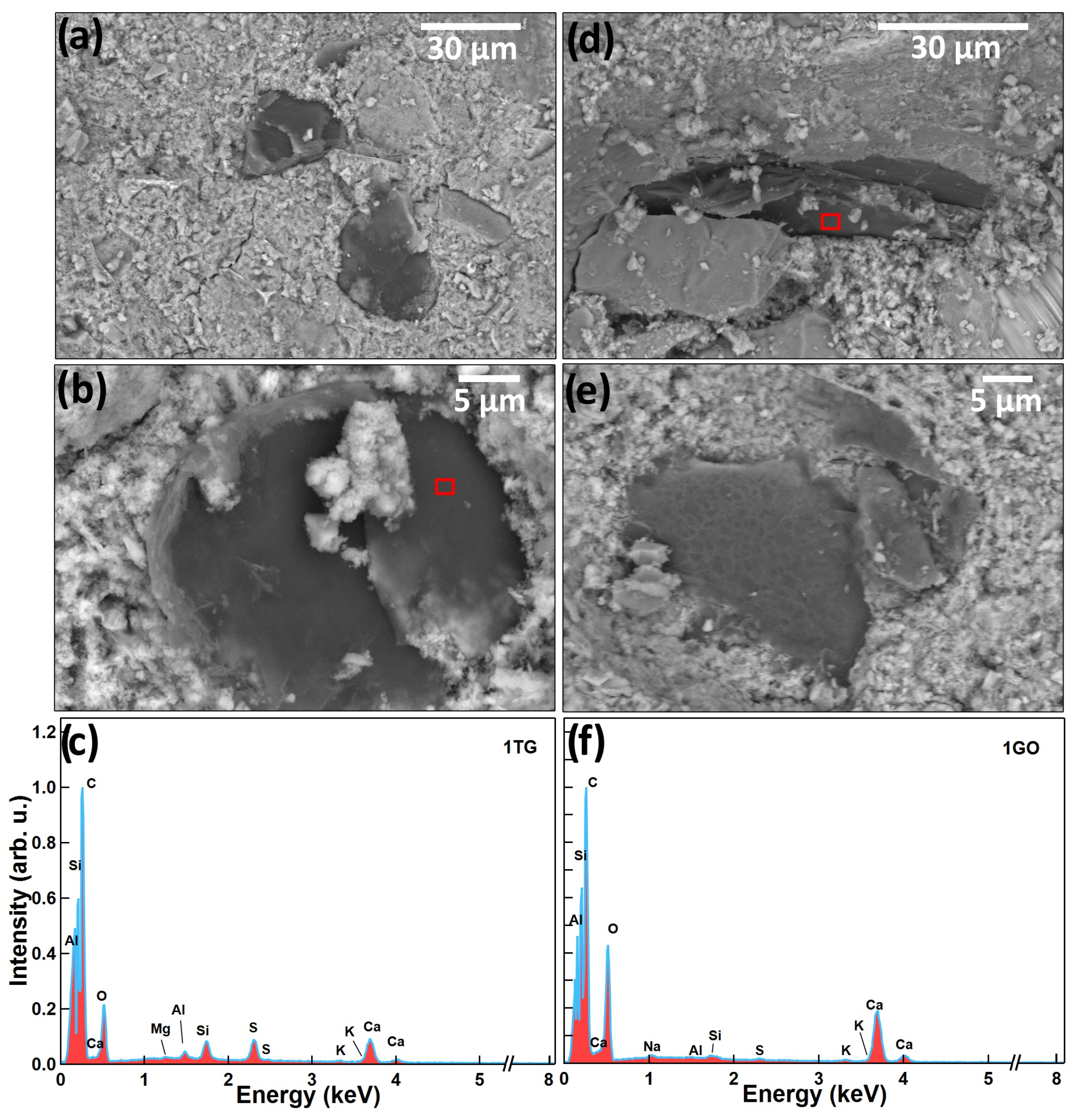
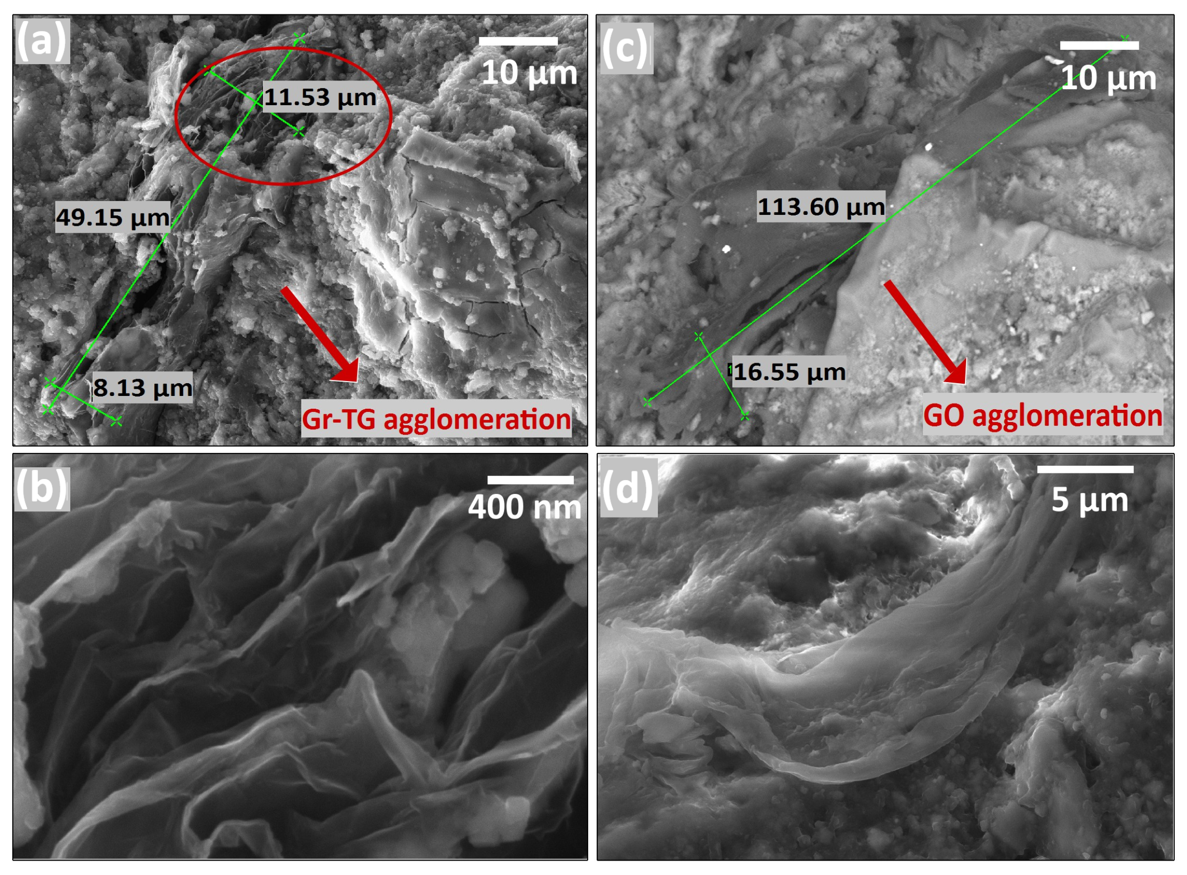
4. FESEM Measurements on Cement Mortar Specimens

In order to investigate the presence of graphene additives and explore their dispersion in the cement matrix, as a final step, 1TG and 1GO fragments were analyzed by FESEM. In Figure 9, representative results are shown: the left-hand panels refer to the 1TG specimen, and the right-hand ones refer to 1GO. Figure 9a shows a Gr-TG flake halting the crack’s propagation, while in Figure 9b, a flake filling a circular pore created by an air void is visible. To better identify graphene flakes incorporated within the mortar, the back-scattered electron mode was used. In this mode, images are displayed in grayscale, with variations dependent on the atomic weight of the material. Since C is the lightest element compared to others present (such as O, Na, Mg, Al, Si, S, K, Ca, Fe), it appears the darkest. Once we identified the graphene flakes, an EDX analysis was performed to check the chemical composition.
The extrapolated EDX from the latter flake is shown below (Figure 9c). GO flakes are shown in Figure 9d,e at different length scales. The EDX spectrum shown in Figure 9f is referred to the GO flake of Figure 9d.
Both EDX spectra (normalised to the carbon peak) show the presence of Al, Si, and Ca, typical components of OPC. In addition, as expected, the spectrum of 1GO shows that the oxygen peak is double that of 1TG. When 1.0 wt% of Gr-TG and 1.0 wt% of GO are added to the admixture, they do not disperse uniformly, thus forming isolated flakes and clusters (Figure 10a,c).
As evidenced in Figure 10b,d, no hydration products of cement are found among the overlapped layers of Gr-TG and GO. In this case, sheets are prone to promptly ungroup or slide over each other when stresses are applied around the cluster, as seen in Figure 10d. This finding can explain why these dosages failed to improve the mechanical properties.

5. Conclusions

In the present study Gr-TG, Gr-SG and GO were used to manufacture cement mortars. The graphene-based nanomaterials were added up to 1.0% by weight of cement.
For the first time, to the best of our knowledge, a novel, robust, affordable technique, the static multiple light scattering (SMLS), was proposed and used to assess the stability of the dispersion of the graphene-based nanomaterials. The results showed that the most efficient pre-treatment to improve both dispersion stabilization and exfoliation, among those analyzed, is the two-step process, characterized by an initial hydrothermal treatment aided by sodium cholate, followed by sonication.
As expected, a decrease in workability was measured with the increase of carbon nanomaterials, more marked with the addition of Gr-SG. It can be ascribed to its higher SSA.
Despite the increased stability of the dispersions, only a limited increase in the compressive strength of mortars was observed with the addition of 0.3 wt% of Gr-TG and 0.3 wt% of Gr-SG, around 15% and 12%, respectively. The highest dosages of graphene-based nanomaterials do not further improve the mechanical properties. Specifically, at those concentrations, carbon nanomaterials form isolated flakes and clusters, characterized by overlapped layers with no evidence of cement hydration products among them. As a consequence, they are prone to promptly ungroup or slide over each other when stresses are applied around the clusters.
A reduction in capillary water absorption of approximately 20% was measured for a Gr-TG concentration of 1.0 wt%, which can be attributed to the refinement of porosity caused by carbon nanomaterials. The outcome of the present investigation allows us to highlight the areas where further research is needed to fully exploit the properties of the carbon-based nanomaterials in cement mortars. Not only is it required to ensure their stable dispersion in water, but it is also crucial to provide efficient routes to increase their degree of exfoliation and functionalize them to improve their interlocking with the cementitious matrix.

Author Contributions

T.G.: Writing the draft, data curation. S.B.: Performed N2 measurements and porosimetries data curation. C.P.B., A.P. and R.G.A.: Performed N2 measurements and review. M.M. and A.T.: Performed MIP measurements and review. M.D.: Performed FESEM analyses and review. A.S. and L.S.C.: Performed Raman analyses and review. S.C. and D.P.: Designed this study, supervision, writing—review and editing. All authors have read and agreed to the published version of the manuscript.

Funding

Part of this work was funded by Italian Ministry of University and Research, project “STAR2—PIR-00008”.

Institutional Review Board Statement

Not applicable.

Informed Consent Statement

Not applicable.

Data Availability Statement

The original contributions presented in this study are included in the article. Further inquiries can be directed to the corresponding author.

Conflicts of Interest

The authors declare no conflicts of interest.

Abbreviations

The following abbreviations are used in this manuscript:
BETBrunauer–Emmett–Teller
BJHBarrett–Joyner–Halenda
BSBackScattered light
CPVCumulative Pore Volume
CWACapillary Water Absorption
EDXEnergy Dispersive X-ray
FESEMField Emission Scanning Electron Microscopy
GNPGraphene NanoPlatelet
GOGraphene Oxide
GrGraphene
Gr-SGGraphene Super Grade
Gr-TGGraphene Technical Grade
HTHydrothermal Treatment
ITZInterfacial Transition Zone
LPELiquid Phase Exfoliation
MIPMercury Intrusion Porosimetry
OPCOrdinary Portland Cement
PESDPore Entrance Size Distribution
PSDPore Size Distribution
PVPore Volume
SSorpitivity
SCSodium Cholate
SMLSStatic Multiple Light Scattering
SPSuperPlasticizer
SSASpecific Surface Area
TTransmitted light
TOFTime of Flight
TSITurbiscan Stability Index

Appendix A. Raw Data for Porosimetry Study

In Figure A1, the original data used to study the porosity ranges that affect the phenomenon of capillary water absorption are shown. The following data were processed, combining Hg porosimetry data above 50 nm (Figure A1a) with those obtained from N 2 below 50 nm (Figure A1b). Details are reported in Section 3.7.
Figure A1. Raw data of CPV, plotted in logarithmic scale, acquired by: (a) MIP (up to 12,000 nm); (b) N 2 porosimetry (up to 120 nm).
Applsci 15 00835 g0a1

References

  1. Stankovich, S.; Dikin, D.A.; Dommett, G.H.B.; Kohlhaas, K.M.; Zimney, E.J.; Stach, E.A.; Piner, R.D.; Nguyen, S.T.; Ruoff, R.S. Graphene-based composite materials. Nature 2006, 442, 282–286. [Google Scholar] [CrossRef] [PubMed]
  2. Zheng, Q.; Han, B.; Cui, X.; Yu, X.; Ou, J. Graphene-engineered cementitious composites: Small makes a big impact. Nanomater. Nanotechnol. 2017, 7, 1847980417742304. [Google Scholar] [CrossRef]
  3. Shamsaei, E.; de Souza, F.B.; Yao, X.; Benhelal, E.; Akbari, A.; Duan, W. Graphene-based nanosheets for stronger and more durable concrete: A review. Constr. Build. Mater. 2018, 183, 642–660. [Google Scholar] [CrossRef]
  4. Wang, B.; Pang, B. Mechanical property and toughening mechanism of water reducing agents modified graphene nanoplatelets reinforced cement composites. Constr. Build. Mater. 2019, 226, 699–711. [Google Scholar] [CrossRef]
  5. Du, H.; Pang, S.D. Enhancement of barrier properties of cement mortar with graphene nanoplatelet. Cem. Concr. Res. 2015, 76, 10–19. [Google Scholar] [CrossRef]
  6. Liu, J.; Fu, J.; Yang, Y.; Gu, C. Study on dispersion, mechanical and microstructure properties of cement paste incorporating graphene sheets. Constr. Build. Mater. 2019, 199, 1–11. [Google Scholar] [CrossRef]
  7. Meng, W.; Khayat, K.H. Effect of graphite nanoplatelets and carbon nanofibers on rheology, hydration, shrinkage, mechanical properties, and microstructure of UHPC. Cem. Concr. Res. 2018, 105, 64–71. [Google Scholar] [CrossRef]
  8. Matalkah, F.; Soroushian, P. Graphene nanoplatelet for enhancement the mechanical properties and durability characteristics of alkali activated binder. Constr. Build. Mater. 2020, 249, 118773. [Google Scholar] [CrossRef]
  9. Sedaghat, A.; Ram, M.K.; Zayed, A.; Kamal, R.; Shanahan, N. Investigation of physical properties of graphene-cement composite for structural applications. Open J. Compos. Mater. 2014, 2014. [Google Scholar] [CrossRef]
  10. Lin, Y.; Du, H. Graphene reinforced cement composites: A review. Constr. Build. Mater. 2020, 265, 120312. [Google Scholar] [CrossRef]
  11. Sun, S.; Ding, S.; Han, B.; Dong, S.; Yu, X.; Zhou, D.; Ou, J. Multi-layer graphene-engineered cementitious composites with multifunctionality/intelligence. Compos. Part B Eng. 2017, 129, 221–232. [Google Scholar] [CrossRef]
  12. Dong, W.; Li, W.; Vessalas, K.; He, X.; Sun, Z.; Sheng, D. Piezoresistivity deterioration of smart graphene nanoplate/cement-based sensors subjected to sulphuric acid attack. Compos. Commun. 2021, 23, 100563. [Google Scholar] [CrossRef]
  13. Dong, W.; Li, W.; Zhu, X.; Sheng, D.; Shah, S.P. Multifunctional cementitious composites with integrated self-sensing and hydrophobic capacities toward smart structural health monitoring. Cem. Concr. Compos. 2021, 118, 103962. [Google Scholar] [CrossRef]
  14. Chuah, S.; Pan, Z.; Sanjayan, J.G.; Wang, C.M.; Duan, W.H. Nano reinforced cement and concrete composites and new perspective from graphene oxide. Constr. Build. Mater. 2014, 73, 113–124. [Google Scholar] [CrossRef]
  15. Collins, F.; Lambert, J.; Duan, W.H. The influences of admixtures on the dispersion, workability, and strength of carbon nanotube–OPC paste mixtures. Cem. Concr. Compos. 2012, 34, 201–207. [Google Scholar] [CrossRef]
  16. Shang, Y.; Zhang, D.; Yang, C.; Liu, Y.; Liu, Y. Effect of graphene oxide on the rheological properties of cement pastes. Constr. Build. Mater. 2015, 96, 20–28. [Google Scholar] [CrossRef]
  17. Liu, C.; Hunag, X.; Wu, Y.Y.; Deng, X.; Zheng, Z.; Yang, B. Studies on mechanical properties and durability of steel fiber reinforced concrete incorporating graphene oxide. Cem. Concr. Compos. 2022, 130, 104508. [Google Scholar] [CrossRef]
  18. Polverino, S.; Del Rio Castillo, A.E.; Brencich, A.; Marasco, L.; Bonaccorso, F.; Morbiducci, R. Few-Layers Graphene-Based Cement Mortars: Production Process and Mechanical Properties. Sustainability 2022, 14, 784. [Google Scholar] [CrossRef]
  19. Balandin, A.A.; Ghosh, S.; Bao, W.; Calizo, I.; Teweldebrhan, D.; Miao, F.; Lau, C.N. Superior thermal conductivity of single-layer graphene. Nano Lett. 2008, 8, 902–907. [Google Scholar] [CrossRef]
  20. Bolotin, K.I.; Sikes, K.; Jiang, Z.; Klima, M.; Fudenberg, G.; Hone, J.; Kim, P.; Stormer, H.L. Ultrahigh electron mobility in suspended graphene. Solid State Commun. 2008, 146, 351–355. [Google Scholar] [CrossRef]
  21. Zhu, Y.; Murali, S.; Cai, W.; Li, X.; Suk, J.W.; Potts, J.R.; Ruoff, R.S. Graphene and graphene oxide: Synthesis, properties, and applications. Adv. Mater. 2010, 22, 3906–3924. [Google Scholar] [CrossRef] [PubMed]
  22. Zhang, S.; Ukrainczyk, N.; Zaoui, A.; Koenders, E. Electrical conductivity of geopolymer-graphite composites: Percolation, mesostructure and analytical modeling. Constr. Build. Mater. 2024, 411, 134536. [Google Scholar] [CrossRef]
  23. Li, W.; Qu, F.; Dong, W.; Mishra, G.; Shah, S.P. A comprehensive review on self-sensing graphene/cementitious composites: A pathway toward next-generation smart concrete. Constr. Build. Mater. 2022, 331, 127284. [Google Scholar] [CrossRef]
  24. Dimov, D.; Amit, I.; Gorrie, O.; Barnes, M.D.; Townsend, N.J.; Neves, A.I.; Withers, F.; Russo, S.; Craciun, M.F. Ultrahigh performance nanoengineered graphene–concrete composites for multifunctional applications. Adv. Funct. Mater. 2018, 28, 1705183. [Google Scholar] [CrossRef]
  25. Wang, B.; Jiang, R.; Wu, Z. Investigation of the Mechanical Properties and Microstructure of Graphene Nanoplatelet-Cement Composite. Nanomaterials 2016, 6, 200. [Google Scholar] [CrossRef]
  26. Pan, Z.; He, L.; Qiu, L.; Korayem, A.H.; Li, G.; Zhu, J.W.; Collins, F.; Li, D.; Duan, W.H.; Wang, M.C. Mechanical properties and microstructure of a graphene oxide–cement composite. Cem. Concr. Compos. 2015, 58, 140–147. [Google Scholar] [CrossRef]
  27. Yan, X.; Zheng, D.; Yang, H.; Cui, H.; Monasterio, M.; Lo, Y. Study of optimizing graphene oxide dispersion and properties of the resulting cement mortars. Constr. Build. Mater. 2020, 257, 119477. [Google Scholar] [CrossRef]
  28. Zhou, Y.; Wang, Y.; Gao, T.; Ling, Y.; Jiang, N.; Tawfek, A.M.; Yuan, H. Optimization of Graphene Nanoplatelets Dispersion and Its Performance in Cement Mortars. Materials 2022, 15, 7308. [Google Scholar] [CrossRef]
  29. Mukhopadhyay, T.; Datta, A. Disentangling the liquid phase exfoliation of two- dimensional materials: An ”in silico” perspective. Phys. Chem. Chem. Phys. 2020, 22, 22157–22179. [Google Scholar] [CrossRef]
  30. Han, J.; Jang, J.; Kim, H.; Hwang, J.Y.; Yoo, H.K.; Woo, J.; Choi, S.; Kim, H.; Jeong, H.; Jeong, S.; et al. Extremely Efficient Liquid Exfoliation and Dispersion of Layered Materials by Unusual Acoustic Cavitation. Sci. Rep. 2014, 4, 5133. [Google Scholar] [CrossRef]
  31. Paton, K.; Varrla, E.; Backes, C.; Smith, R.; Khan, U.; Gallagher, A.; Boland, C.; Lotya, M.; Istrate, O.; King, P.; et al. Scalable production of large quantities, defect-free few-layer graphene by shear exfoliation in liquids. Nat. Mater. 2014, 13, 624–630. [Google Scholar] [CrossRef] [PubMed]
  32. Paton, K.R.; Anderson, J.; Pollard, A.J.; Sainsbury, T. Production of few-layer graphene by microfluidization. Mater. Res. Express 2017, 4, 025604. [Google Scholar] [CrossRef]
  33. Ramalingam, P.; Pusuluri, S.T.; Periasamy, S.; Veerabahu, R.; Kulandaivel, J. Role of deoxy group on the high concentration of graphene in surfactant/water media3. RSC Adv. 2013, 3, 2369–2378. [Google Scholar] [CrossRef]
  34. Yang, Q.; Zhou, M.; Yang, M.; Zhang, Z.; Yu, J.; Zhang, Y.; Cheng, W.; Li, X. High-Yield Production of Few-Layer Graphene via New-fashioned Strategy Combining Resonance Ball Milling and Hydrothermal Exfoliation. Nanomaterials 2020, 10, 667. [Google Scholar] [CrossRef]
  35. Wei, X.X.; Jia, Q.; Zheng, C.; Zhu, J.H.; Pei, C. Enhancement in durability and performance for cement-based materials through tailored water-based graphene nanofluid additives. Constr. Build. Mater. 2024, 457, 139455. [Google Scholar] [CrossRef]
  36. Nochaiya, T.; Chaipanich, A. Behavior of multi-walled carbon nanotubes on the porosity and microstructure of cement-based materials. Appl. Surf. Sci. 2011, 257, 1941–1945. [Google Scholar] [CrossRef]
  37. Chen, J.; Kou, S.; Poon, C.S. Hydration and properties of nano-TiO2 blended cement composites. Cem. Concr. Compos. 2012, 34, 642–649. [Google Scholar] [CrossRef]
  38. Jing, G.; Ye, Z.; Wu, J.; Wang, S.; Cheng, X.; Strokova, V.; Nelyubova, V. Introducing reduced graphene oxide to enhance the thermal properties of cement composites. Cem. Concr. Compos. 2020, 109, 103559. [Google Scholar] [CrossRef]
  39. UNI EN 1015-3:2007; Consistency of Wet Mortar. European Committee for Standardization: Brussels, Belgium, 2007.
  40. UNI EN 12504-4:2005; Testing Concrete—PART 4: Determination of Ultrasonic Pulse Velocity. European Committee for Standardization: Brussels, Belgium, 2005.
  41. Hernández, M.; Anaya, J.; Izquierdo, M.; Ullate, L. Application of micromechanics to the characterization of mortar by ultrasound. Ultrasonics 2002, 40, 217–221. [Google Scholar] [CrossRef]
  42. UNI EN 1015-11:2001; Methods of Test for Mortar for Masonry—Determination of Flexural and Compressive Strength of Hardened Mortar. European Committee for Standardization: Brussels, Belgium, 1999.
  43. UNI EN 1015-18; Methods of Test for Mortar for Masonry—Determination of Water Absorption Coefficient Due to Capillary Action of Hardened Mortar. European Committee for Standardization: Brussels, Belgium, 2002.
  44. Candamano, S.; De Luca, P.; Frontera, P.; Crea, F. Production of Geopolymeric Mortars Containing Forest Biomass Ash as Partial Replacement of Metakaolin. Environments 2017, 4, 74. [Google Scholar] [CrossRef]
  45. Jaroniec, M.; Kruk, M.; Sayari, A. Adsorption methods for characterization of surface and structural properties of mesoporous molecular sieves. Stud. Surf. Sci. Catal. 1998, 117, 325–332. [Google Scholar] [CrossRef]
  46. Chen, Z.; Qing, H.; Zhou, K.; Sun, D.; Wu, R. Metal-organic framework-derived nanocomposites for electrocatalytic hydrogen evolution reaction. Prog. Mater. Sci. 2020, 108, 100618. [Google Scholar] [CrossRef]
  47. Li, Z.; Kruk, M.; Jaroniec, M. Synthesis and adsorption properties of novel carbons of tailored porosity. Stud. Surf. Sci. Catal. 2002, 141, 345–352. [Google Scholar] [CrossRef]
  48. Barrett, E.P.; Joyner, L.G.; Halenda, P.P. The determination of pore volume and area distributions in porous substances. I. computations from nitrogen isotherms. J. Am. Chem. Soc. 1951, 73, 373–380. [Google Scholar] [CrossRef]
  49. Davankov, V.; Tsyurupa, M. Properties of Hypercrosslinked Polystyrene. Compr. Anal. Chem. 2011, 56, 195–295. [Google Scholar] [CrossRef]
  50. Parveen, S.; Rana, S.; Fangueiro, R. A review on nanomaterial dispersion, microstructure, and mechanical properties of carbon nanotube and nanofiber reinforced cementitious composites. J. Nanomater. 2013, 2013, 710175. [Google Scholar] [CrossRef]
  51. Ferrari, A.C.; Meyer, J.C.; Scardaci, V.; Casiraghi, C.; Lazzeri, M.; Mauri, F.; Piscanec, S.; Jiang, D.; Novoselov, K.S.; Roth, S.; et al. Raman spectrum of graphene and graphene layers. Phys. Rev. Lett. 2006, 97, 187401. [Google Scholar] [CrossRef]
  52. Malard, L.M.; Pimenta, M.A.; Dresselhaus, G.; Dresselhaus, M.S. Raman spectroscopy in graphene. Phys. Rep. 2009, 473, 51–87. [Google Scholar] [CrossRef]
  53. Backes, C.; Paton, K.; Hanlon, D.; Yuan, S.; Katsnelson, M.; Houston, J.; Smith, R.; Mccloskey, D.; Donegan, J.; Coleman, J. Spectroscopic metrics allow in-situ measurement of mean size and thickness of liquid-exfoliated graphene nanosheets. Nanoscale 2016, 8, 4311–4323. [Google Scholar] [CrossRef]
  54. Stankovich, S.; Dikin, D.A.; Piner, R.D.; Kohlhaas, K.A.; Kleinhammes, A.; Jia, Y.; Wu, Y.; Nguyen, S.T.; Ruoff, R.S. Synthesis of graphene-based nanosheets via chemical reduction of exfoliated graphite oxide. Carbon 2007, 45, 1558–1565. [Google Scholar] [CrossRef]
  55. Kaniyoor, A.; Ramaprabhu, S. A Raman spectroscopic investigation of graphite oxide derived graphene. Aip Adv. 2012, 2. [Google Scholar] [CrossRef]
  56. Samimi, K.; Pakan, M.; Eslami, J.; Asgharnejad, L. Investigation of two different water-dispersed graphene on the performance of graphene/cement paste: Surfactant and superplasticizer effect. Constr. Build. Mater. 2022, 349, 128756. [Google Scholar] [CrossRef]
  57. Wang, Y.; Li, L.; An, M.; Sun, Y.; Yu, Z.; Huang, H. Factors Influencing the Capillary Water Absorption Characteristics of Concrete and Their Relationship to Pore Structure. Appl. Sci. 2022, 12, 2211. [Google Scholar] [CrossRef]
  58. Gao, Y.; Jing, H.; Zhou, Z.; Chen, W.; Du, M.; Du, Y. Reinforced impermeability of cementitious composites using graphene oxide-carbon nanotube hybrid under different water-to-cement ratios. Constr. Build. Mater. 2019, 222, 610–621. [Google Scholar] [CrossRef]
  59. Sills, I.; Aylmore, L.; Quirk, J. A comparison between mercury injection and nitrogen sorption as methods of determining pore size distributions. Soil Sci. Soc. Am. J. 1973, 37, 535–537. [Google Scholar] [CrossRef]
  60. Wu, Z. Discussion on the recent development direction of concrete science and technology. J. Chin. Ceram. Soc 1979, 3, 262–270. [Google Scholar]
  61. Brown, S.M.; Lard, E.W. A comparison of nitrogen and mercury pore size distributions of silicas of varying pore volume. Powder Technol. 1974, 9, 187–190. [Google Scholar] [CrossRef]
  62. Hajnos, M. Porosimetry; Springer: Dordrecht, The Netherlands, 2011; pp. 647–650. [Google Scholar] [CrossRef]
  63. Milburn, D.R.; Davis, B.H. Comparison of surface areas calculated from nitrogen adsorption and Mercury porosimetry. In A Collection of Papers on Engineering Aspects of Fabrication of Ceramics: Ceramic Engineering and Science Proceedings; The American Ceramics Society: Westerville, OH, USA, 1993; Volume 14, pp. 130–134. [Google Scholar] [CrossRef]
  64. Wang, X. Chapter 3—Lacustrine Shale Gas Reservoir in the Ordos Basin. In Lacustrine Shale Gas; Wang, X., Ed.; Gulf Professional Publishing: Houston, TX, USA, 2017; pp. 93–178. [Google Scholar] [CrossRef]
  65. Pastorino, D.; Canal, C.; Ginebra, M.P. Multiple characterization study on porosity and pore structure of calcium phosphate cements. Acta Biomater. 2015, 28, 205–214. [Google Scholar] [CrossRef]
  66. Lai, W.; Yang, S.; Jiang, Y.; Zhao, F.; Li, Z.; Zaman, B.; Fayaz, M.; Li, X.; Chen, Y. Artefact peaks of pore size distributions caused by unclosed sorption isotherm and tensile strength effect. Adsorption 2020, 26, 633–644. [Google Scholar] [CrossRef]
Figure 1. Sand gradation.
Applsci 15 00835 g001
Figure 2. FESEM analyses on as-received Gr-TG fragments: (a) magnification 2000×; (b) multilayered region with some typical dimensions, magnification 120,000×; (c) magnification 300,000× of a few layered region. FESEM analyses on as-received GO fragments: (d) magnification 2000×; (e) magnification 120,000×; (f) magnification 240,000×.
Applsci 15 00835 g002
Figure 3. Raman spectra of: (a) as-received Gr-TG (grey line); D-TGb dispersion after HT treatment (red line); D-TGb dispersion after HT and LPE treatments (blue line). In the inset, a zoom-up of 2D bands with their relative intensity is reported. (b) Raman spectra of D-GOb (red line) and as-received GO (black line). For each sample, twenty spectra were acquired in different regions. Background subtraction and normalisation to the G peak were applied, then an average was calculated among the resulting spectra.
Applsci 15 00835 g003
Figure 4. Results of TSI values for D-TGb (HT + LPE), D-TGb (LPE), and D-GOb specimens. (a) Graph on logarithmic scale with the stability index variation measured every 5 min for a total time of 180 min; (b) histogram on logarithmic scale with TSI values at 5, 60 and 180 min. The colour scale bar shows the corresponding grade of suspension.
Applsci 15 00835 g004
Figure 5. Results of: (ac) ultrasonic, (df) flexural strength, (gi) compressive strength tests, plotted as a function of the additive concentration. Higher panels are referred to as Gr-TG; middle panels to Gr-SG; lower panels to GO.
Applsci 15 00835 g005
Figure 6. Calculated sorptivity values for: (a) GO and C; (b) Gr-TG, Gr-SG and C mortars. (c) Comparison between CWA measurements of 1TG and C mortars.
Applsci 15 00835 g006
Figure 7. N 2 adsorption/desorption isotherms for: (a) C, (b) 1TG and (c) 1GO samples. PSD and PESD obtained for: (d) C, (e) 1TG and (f) 1GO samples.
Applsci 15 00835 g007
Figure 8. (a) CPV plotted in logarithmic scale in the range [0–12,000] nm. (b) Histogram with PV contributions for each range, showing the range in which each specimen demonstrates the greatest contribution to porosity.
Applsci 15 00835 g008
Figure 9. FESEM images in back-scattering mode of Gr-TG and GO flakes within 1TG and 1GO specimen fragments: (a) Gr-TG flake halting the crack’s propagation; (b) Gr-TG flake filling a circular pore created by an air void; (d,e) GO flakes at different length scale. Examples of EDX spectra of (c) Gr-TG and (f) GO flakes of highlighted regions (red boxes) of doped cement mortar fragments.
Applsci 15 00835 g009
Figure 10. FESEM images of Gr-TG and GO flakes within 1TG and 1GO specimen fragments: (a) agglomeration of Gr-TG flakes; (b) zoom-up of the region in the red ellipses; (c) agglomeration of GO flakes; (d) isolated GO flake within the matrix, taken in scanning mode.
Applsci 15 00835 g010
Table 1. Physical and chemical properties of raw materials used for mortar specimens. The elemental composition shows, in percentage, the main elements reported by the manufacturer: carbon (C), oxigen (O), and sulphur (S).
RawCharacteristics
Materials
CementManufactured in accordance to standard UNI EN 197-1. Main Components, in  terms of oxides:
SiO2 = 18.61 wt%; Fe2O3 = 2.87 wt%; Al2O3 = 4.38 wt%; CaO = 60.60 wt%; MgO = 3.16 wt%;
K2O = 0.79 wt%; Na2O = 0.35 wt%; MnO = 0.17 wt%; SO3 = 2.83 wt%; TiO2 = 0.2 wt%.
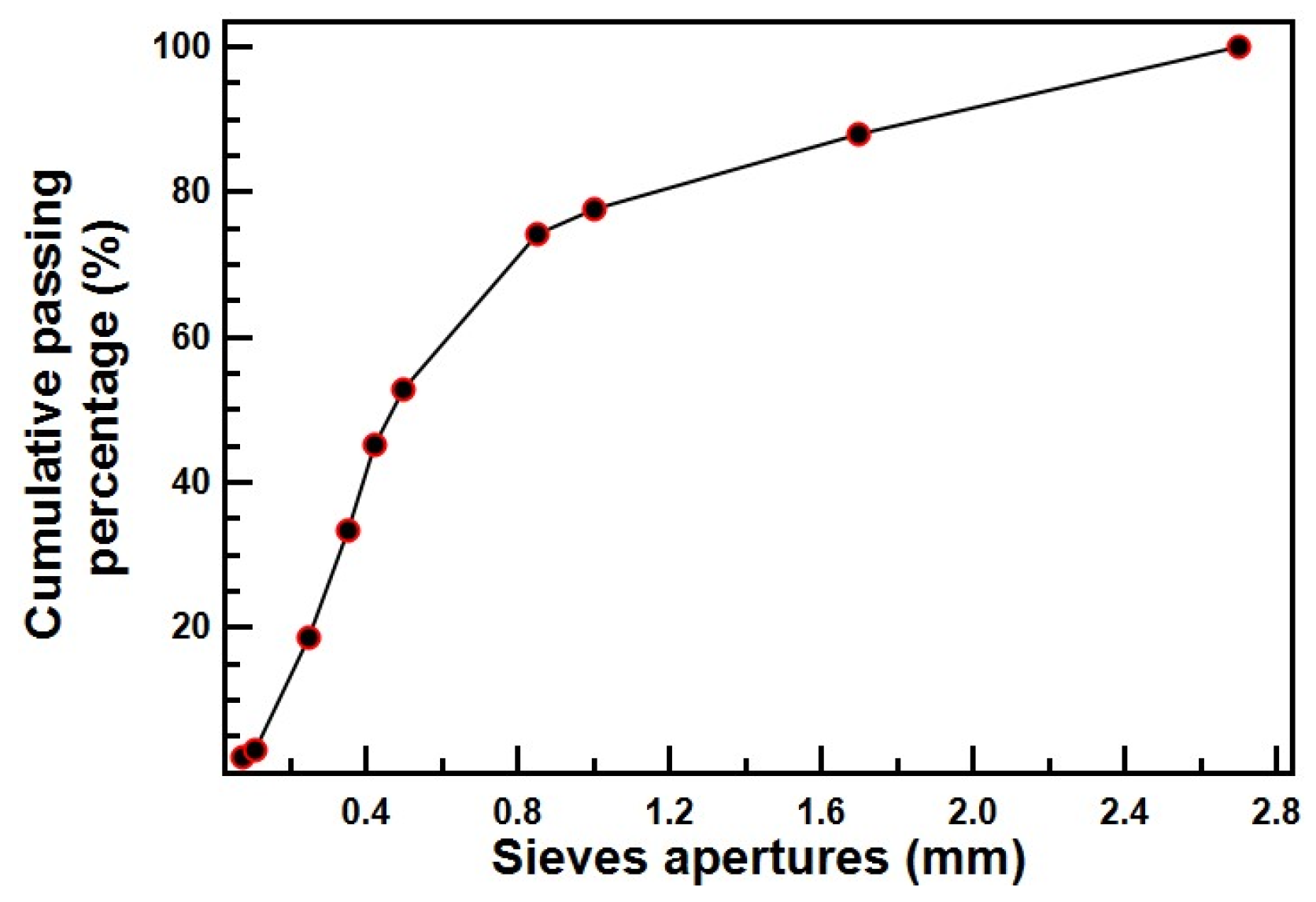
Particle size distribution, based on volume distribution: D10 = 8.414 µm; D50 = 19.84 µm;
 D90 = 36.11 µm.
AdditiveSSAThicknessLateral BulkElemental composition (%)
type(m2/g)(nm)sizedensityCOS
(g/cm3)
 Gr-TG 8010–2010 µm0.25>99<1 <1
 Gr-SG>2501.66–100 nm0.06>99 00
GO 35010–20<10 µm0.3574 250.34
Table 2. Composition of the graphene-based dispersions and related pretreatments. Labelling explanation: “D” denotes “dispersion”, “a” and “b” the minimum and maximum concentration, respectively.
Sample
Label
Additive
Type
Additive
Concentr.
(wt%)
SC/Additive
Ratio
HT
Treat.
(h–°C)
LPE
Treat.
(h)
D-TGaGr-TG1.531/56–1806
D-TGbGr-TG2.501/56–1806
D-SGaGr-SG1.531/56–1806
D-GOaGO1.53006
D-GObGO2.50006
Table 3. Mix designs of mortars.
Mortar
Label
Dispersion
Type
Carbon Nanomaterial
(wt% *)
w/c
Ratio by wt.
s/c
Ratio by wt.
SP/c
Ratio by wt.
C-00.4752.50.009
01TGD-TGa0.10.4752.50.009
03TGD-TGa0.30.4752.50.009
05TGD-TGb0.50.4752.50.009
1TGD-TGb1.00.4752.50.009
01SGD-SGa0.10.4752.50.009
03SGD-SGa0.30.4752.50.009
01GOD-GOa0.10.4752.50.009
05GOD-GOb0.50.4752.50.009
1GOD-GOb1.00.4752.50.009
* by weight of cement
Table 4. Acquired data of workability test with corresponding errors.
SpecimenW (%)ΔW
C119.050.05
03SG64.760.05
03TG116.190.13
01GO106.190.20
05GO108.040.08
1GO70.890.18
Disclaimer/Publisher’s Note: The statements, opinions and data contained in all publications are solely those of the individual author(s) and contributor(s) and not of MDPI and/or the editor(s). MDPI and/or the editor(s) disclaim responsibility for any injury to people or property resulting from any ideas, methods, instructions or products referred to in the content.

