Article

Application of Long-Distance Drilling and Blasting Technology to Prevent Rock Bursts in High-Level Roofs

School of Mines, China University of Mining and Technology, Xuzhou 221116, China
*
Author to whom correspondence should be addressed.
Appl. Sci. 2025, 15(4), 1821; https://doi.org/10.3390/app15041821
Submission received: 20 December 2024 / Revised: 4 February 2025 / Accepted: 5 February 2025 / Published: 11 February 2025

Abstract

:
In view of the high-level, thick, and hard roof in a mine in Shaanxi, it is difficult for existing technology to solve the problem of frequent rock bursts, which are caused by the direct weakening of the whole underground layer. In this paper, a technology for preventing rock bursts using the long-distance drilling and blasting of a thick and hard roof in a high drilling field is proposed. The authors used theoretical analyses, numerical simulations, and other research methods to analyze the mechanisms of pressure relief and load reduction achieved by this technology, determined its layout parameters and layers, and carried out engineering practices in 2412 working faces in a mine in Shaanxi. The results show that the long-distance drilling and blasting technology can achieve the aim of unloading the pressure drop load by arranging a high-level drilling field to achieve the whole-layer presplitting of the thick and hard roof above the working face. According to the orthogonal test method, when using long-distance drilling and blasting under the condition of a high-level roof, the choice of the blasting layer is the biggest factor affecting the change in overburden subsidence. Using the identification basis of the main control disaster causing the layer of overburden, it was determined that 52~67 m above the coal seam of the 2412 working faces was the blasting layer. According to the periodic weighting interval of the working face and the development radius of the fractures in the blasting surrounding rock, the blast hole spacing was determined to be 30 m. After long-distance drilling and blasting, the frequency and energy of micro seismic events were reduced, the entry deformation was reduced compared with the common roof deep-hole blasting technology, and the pressure relief effect of the long-distance drilling and blasting technology was better. These research conclusions can provide theoretical support for the prevention and control of rock bursts during mining production under similar conditions by reducing the load and the unloading pressure on thick and hard roof layers that are difficult to unload from the source.

1. Introduction

With the increasing depth of coal mining around the world, rock burst disasters are becoming more and more prevalent, which seriously restricts the safe production activities of mines [1,2]. The prevention and control of deep rock burst disasters has become one of the focuses of academic research. A thick and hard roof is one of the main influencing factors of rock burst disasters [3,4]. As the lithology of such roofs is hard, making them difficult to collapse, it is easy to create a large area of suspended roof during the mining process of the working face. Any sudden failure and instability will release a large amount of energy, resulting in the occurrence of rock burst disasters, which pose a great threat to the safe production of the working face [5]. According to the drilling data, there are hard sandstone layers (groups) with a thickness of 10~49 m within 100 m above the coal seam in the Binchang mining area, Shaanxi Province. It is easy to create a hanging roof, leading to a stress concentration, aggravating the complexity of the stress field, and easily inducing rock burst disasters. Therefore, the prevention and control of thick and hard roofs is of great significance to the safe production of the Binchang mining area.
The weakening treatment of thick and hard roofs is a powerful way to prevent and control rock burst disasters from the source. Many scholars at home and abroad have done a lot of research into the prevention and control technology of thick and hard roof rock bursts [6]. Based on the mechanism of a rock burst being induced by a deep, hard roof, Zhu Sitao and Sun Wenchao et al. [7,8] proposed targeted prevention and control measures to avoid a hanging roof disaster. Mu et al. [9] proposed prevention and control measures of hard roof rock bursts that used numerical simulations to release elastic energy by blasting the roof and carried out the engineering verification in the Jisan Coal Mine. Alex Hall [10] analyzed the mechanism of roof deep-hole blasting and applied it in field practice by studying the relationship between rock fractures and rock bursts. Tang B., Vennes I, and other scholars [11,12] studied the influence of blasting on anti-impact and decompression by establishing models and put forward the advantages of deep-hole blasting technology. Junwen Zhang, Lv H, and Dai X [13,14,15] established a mechanical model of roof instability in hard rock strata and revealed the mechanism of rock bursts under the condition of a thick and hard roof. Taking the 401102 working face of Mengcun Coal Mine as the research object, Shuo Yang et al. [16] studied the influence of surface hydraulic fracturing on thick and hard key strata and the mechanism of rock bursts and concluded that surface hydraulic fracturing can reduce the disturbance stress by fracturing the complete thick and hard rock strata into multiple rock sections to achieve the purpose of pressure relief. Cheng Lixing et al. [17] studied hydraulic fracturing roof cutting and pressure relief. The results show that hydraulic fracturing can effectively weaken the integrity of the roof and reduce the stress of the surrounding rock. Zhao Shankun et al. [18] took Yuejin Coal Mine as the research object and explored its pressure relief mechanism by analyzing the process and influencing factors of advanced deep-hole roof blasting. Lyu et al. [19] proposed a surface well acid fracturing pressure relief disaster reduction technology for the thick and hard rock strata on the coal mining face. Zheng Kaige, Fu Baojie, and Lai Xingping et al. [20,21,22] used similar simulations, mechanical analyses, and other means to put forward the identification mechanism of a thick and hard roof of composite key stratum, and based on this, the prevention and control methods were optimized. Aiming to solve the problem of thick and hard roofs easily inducing a rock burst risk during mining, Jiao Wei, Wang Shuwen, Fan J, Zhuang J et al. [23,24,25,26] proposed pressure relief and rock burst technologies, such as ground fracturing and underground, directional, deep-hole hydraulic fracturing. Bin Yu et al. [27] analyzed the influence of roof thickness, cantilever length, and other factors on roof rock burst load and elastic energy by establishing a roof failure model and put forward the technology of ground hydraulic fracturing and liquid explosions in deep holes to eliminate the influence of disasters. Pan Junfeng et al. [28] reduced the stress concentration of the working face based on the method of fracturing the roof area in advance above and below the well and carrying out the artificial liberation layer mining, thereby reducing the rock burst risk of the mining activity space in a large range.
The above research focuses on the problem of rock burst disasters caused by thick and hard roofs. Theoretical analysis and numerical simulation methods are used to study the prevention and control methods of rock bursts in thick and hard roofs. Roof deep hole blasting, hydraulic fracturing, and other technologies for low-level roofs, as well as ground hydraulic fracturing technology that can be used for high-level roofs, are proposed. However, in view of the high layer of thick and hard rock strata, it is difficult to relieve the pressure of the thick and hard roof due to the limitation of construction conditions and technical parameters. Therefore, this paper proposes a long-distance drilling blasting technology and conducts an application study in the 2412 working face of the second district of a mine in Binchang mining area, Shaanxi Province. The mechanism of load reduction and rock burst reduction of long-distance drilling blasting pressure relief and rock burst technology is expounded. A simulation scheme is designed by an orthogonal test method for the three blasting influencing factors studied in this paper. The subsidence, stress change, and rock fracture of the overlying strata after high-level roof blasting are analyzed and quantitatively evaluated, and a blasting implementation scheme is designed. Based on the measured micro seismic and entry deformation data, the actual pressure relief effect of long-distance drilling blasting was analyzed, and finally, the safe mining of the working face was realized. This paper provides a reference for the prevention and control of thick and hard roof rock bursts induced in mines with similar conditions to those of our study mine.

2. Engineering Background

2.1. Subsection

The working face is the first site of coal production. The 2412 working face of a rock burst mine in Shaanxi Binchang mining area is located in the east of the 2410 working face. This working face is −705~−750 m in depth, and the thickness of the coal seam is 4.5~14.73 m. The 2412 working face adopts the fully mechanized mining method to mine No.4 coal. There is a syncline crossing the working face, and the syncline name is NXG, as shown in Figure 1. The circles in Figure 1 represent micro seismic events of different energy levels. According to the in-plane ZK5-3 drilling columnar information, it can be seen that the thickness of the No.4 coal seam is about 15 m; the working face layout and ZK5-3 drilling columnar are shown in Figure 1. In the figure, the thickness of the No.4 coal seam is about 15 m, and there is a thick and hard siltstone layer about 52 m above it. There is a thick coarse sandstone layer about 82 m away from the coal seam, which is a high-level thick and hard roof with great influence on the working face.

2.2. Deformation Characteristics of Entry

The hard roof within 100 m above the coal seam of each mine in the Binchang mining area of Shaanxi Province is mainly siltstone, coarse-grained sandstone, and fine-grained sandstone. The key layers are mostly concentrated in the Luohe group and Yijun group. Under normal circumstances, the main roof sandstone group has strong bearing capacity. During the mining process of the working face, a large amount of elastic energy is accumulated in the thick and hard roof of this layer. When the rock mass load exceeds the maximum strength that its bearing system can bear, a large amount of elastic energy is released instantaneously, which will induce rock burst.
From the beginning of mining to the stage of long-distance drilling and blasting, the stress of entry surrounding rock changes greatly under the influence of mining. In the early stage of mining, the plastic zone of entry expands sharply, and the deformation of the surrounding rock increases significantly. Behind the working face, the abutment pressure of entry and the deformation of surrounding rock will reach the maximum values by the roof subsidence movement above the entry and on the side of goaf, and the deformation of the entry surrounding rock is more intense near the fold area.
Therefore, the questions of how to weaken the thick and hard roof of the whole layer and reduce the strength of the pressure are of great significance for the prevention and control of the source of the thick and hard roof rock burst.

3. Mechanism of Load Reduction and Scour Reduction in Long-Distance Drilling Blasting

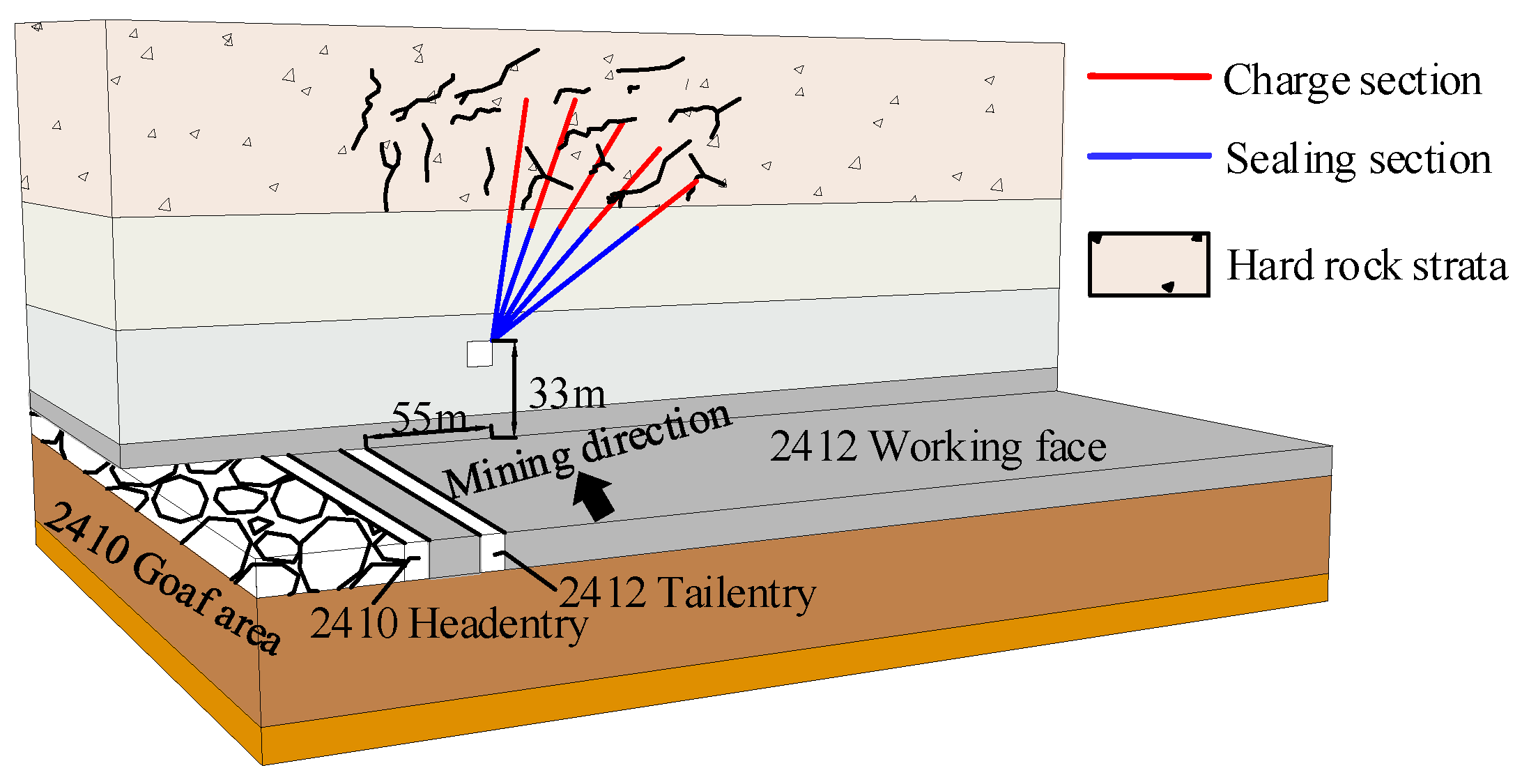
Figure 2 presents a schematic diagram of long-distance borehole blasting. As shown in the figure, a chamber is arranged at the higher position of the roof near the side of the return air roadway, and a high-level drilling field is arranged here. By drilling and blasting inside, the high-level thick and hard rock strata above the working face are pre-cracked obliquely. The hanging roof above the working face before and after long-distance drilling blasting is shown in Figure 3.
As shown in Figure 3, l11 and l21 are the hanging roof length of the upper rock layer of the blasting target layer before and after blasting, l12 and l22 are the hanging roof length of the rock layer of the blasting target layer before and after blasting, σ0 is the primary rock stress at the position of the coal seam before the mining of the working face, σ1 and σ2 are the front abutment pressure of the working face before and after blasting, and x1 and x2 are the distance from the front abutment pressure to the working face before and after blasting.
According to Figure 3, with the mining of the working face, the hanging distance of the upper hard plate is longer, and the concentration degree of the abutment pressure in the working face is high. After the long-distance drilling and blasting, the hanging distance decreases (l11 > l21, l12 > l22), the roof is broken, the rock block changes from large to small, and the concentration degree of the abutment pressure in the working face decreases (σ1 > σ2). At the same time, it can also reduce the dynamic load from the hanging roof fracture zone, so that the overlying load changes from hard transfer to soft transfer, reducing the rock burst risk and achieving low stress mining. Because the load of the overlying strata needs to pass through the blasting layer to the working face, the peak value of the front abutment pressure is also farther from the working face than before the blasting (x2 > x1).
Based on the principle of blasting pressure relief technology for hard roofs, combined with the research results of many scholars on blasting pressure relief technology [29,30,31,32,33], in the practical application of working face, for the whole layer of rock blasting, excluding the layout of blasting hole itself, the nature of explosive itself, and other factors, this paper analyzes the effect of long-distance drilling blasting pressure relief for the following three factors: blasting pre-splitting layer, blasting rock thickness, and blasting rock lithology.

4. Analysis of Influencing Factors of Long-Distance Drilling Blasting

4.1. Numerical Model Establishment and Scheme Design

4.1.1. Numerical Modeling

According to the layout of the 2412 working face in the mine site, combined with the ZK5-3 drilling data in the working face, a UDEC numerical calculation model with a length (x) of 570 m and a height (y) of 260 m was established. UDEC is the abbreviation of Universal Distinct Element Code, which is a computational analysis program based on the theory of discrete element method. Compared with other numerical simulation software, the main advantage of UDEC is that it can simulate the behavior of discontinuous media in geotechnical engineering more accurately and provide more accurate and effective analysis results. Therefore, this paper chooses UDEC as the main simulation method. By referring to the commonly used constitutive model of UDEC in mining engineering [34,35], and considering whether the model can more intuitively reflect the failure mechanism of rock and the computational efficiency, the Mohr-Coulomb failure criterion is used to simulate the rock stratum. The elastic-plastic contact model of the relay zone with Coulomb slip failure was used at the joint of the model block. The X axis was the advancing direction of the working face and the Y axis was the mining depth direction. The buried depth of the model working face was 705 m and the mining height was 15 m. The calculation model was divided into 763,822 grids and 941,184 nodes. The survey line was arranged at the height of 230 m, and the pressure relief effect of long-distance drilling blasting was evaluated by comparing and analyzing the Y-direction subsidence and stress change of overburden rock at the survey line position. The initial model and the division of rock blocks are shown in Figure 4. According to the field measured data, the physical and mechanical parameters of the rock block are shown in Table 1.
The ‘engineering rock mass classification standard’ stipulates that the integrity coefficient of rock mass should be measured when calculating the basic quality index of rock mass. When the measured values are obtained unconditionally, the rock mass integrity coefficient Kv can also be determined by the volume joint number Jv [36,37].
Kv = (Vpm/Vpr)2
In the formula, Kv is the integrity coefficient of rock mass, Vpm is the P-wave velocity of rock mass, and Vpr is the P-wave velocity of original rock mass.
The simulation realizes blasting through the joint encryption division of the blasting layer and the weakening of the rock parameters below the blasting rock layer. The weakening method uses the number of volumetric joints in the original rock mass as the initial base. The integrity coefficient of the rock mass after long-distance drilling and blasting can also be determined by the number of volumetric joints Jp in the rock mass after blasting. The corresponding relationship between the two and the relationship between the integrity coefficient of the rock mass and the number of volumetric joints of the rock mass are the same. A comparison between the two is shown in Table 2.

4.1.2. Simulation Scheme Design

In order to determine the influences of different factors on the effect of blasting pressure relief, the orthogonal test method [37,38] is introduced to examine the influence of the blasting layer position, blasting rock lithology, and blasting rock thickness on the maximum overburden subsidence value and stress value. There are two schemes for blasting layer position, i.e., lithology and thickness, so the orthogonal table L4 (32) with the same level number was selected (see Table 3). The representative parameters were selected as the values of the level. Through the quasi-horizontal method, the test scheme was finally determined, as shown in Table 4.

4.2. Overburden Rock Migration and Stress Variation Characteristics

In order to more clearly and intuitively evaluate the subsidence of overlying strata in coal seam mining before and after blasting, one of the schemes was selected to compare the cloud maps of displacement and stress changes. For example, Figure 5, Figure 6 and Figure 7 show the subsidence, stress change characteristics, and fractures of overlying strata in long-distance drilling blasting for Scheme 1.
Figure 6 is a cloud map of overburden subsidence before and after long-distance borehole blasting, and Figure 7 is a cloud map of maximum principal stress before and after long-distance borehole blasting. By comparing the subsidence cloud map of overburden rock before and after long-distance drilling blasting, it can be seen that after long-distance drilling blasting, the subsidence of overburden rock was V-shaped, and the subsidence value of overburden rock in the middle of working face was the largest. Compared with the mining conditions without blasting, the subsidence range of overburden rock after blasting increased, which indicated that blasting pre-splitting rock stratum can make the rock stratum collapse more fully during the mining process of the working face. Additionally, the roof rock stratum was more broken, so as to minimize the rock burst risk caused by the large-area suspended roof. By comparing the maximum principal stress cloud diagram before and after long-distance drilling blasting, it can be seen that after long-distance drilling blasting, the stress distribution in the roof area was more dispersed, the stress concentration area before blasting was larger, and the stress concentration degree above and below the pre-splitting layer after blasting was reduced.
Figure 8 shows the change of roof rock cracks before and after long-distance borehole blasting. According to the figure, after long-distance borehole blasting, the roof rock was more broken and the fracture range was larger. At the same time, according to the simulation results, the maximum shear stress value before blasting reached 286.88 MPa, and the maximum shear stress value after blasting reached 291.75 MPa. After blasting, the total number of cracks increased from 1232 to 1727, and the total length increased from 119 m to 145 m, which increased by 28.66% and 17.93% respectively. This shows that blasting pre-splitting rock strata can avoid the roof above the working face due to the existence of a large-area suspended roof, an increase in the number of cracks, and avoidance of the accumulation of a large amount of elastic energy, thereby reducing rock burst risk.

4.3. Quantitative Analysis of Pressure Relief Effect

In order to more clearly and intuitively judge the subsidence and stress change of overlying rock after blasting, the two indexes were quantitatively analyzed. Taking Scheme 1 as an example, the subsidence and stress change indexes of the overlying rock before and after blasting were compared and analyzed.
As shown in Figure 8a, during the mining process of the working face, the subsidence value and range of the overlying strata under the condition of long-distance drilling blasting were much larger than those under the condition of conventional mining: the average value of overlying strata subsidence increased by 21.2% after blasting, and the maximum value increased by 15.2%. According to Figure 8b, it can be seen that during the mining process of the working face, the maximum principal stress of the roof after blasting was less than the stress value under the conventional mining conditions. The overall change trend was unchanged, and the stress after blasting was small. The average stress value was reduced by 22.8%, and the maximum stress value was reduced by 34%.
Comparing and analyzing the maximum subsidence value and maximum stress value of overburden rock in the different schemes described in Section 4.2, it can be seen that the subsidence value of overburden rock in Scheme 2 reached the maximum and the stress value was the lowest, which indicated the worst blasting effect compared with the other three schemes.

4.4. Sorting of Main Influencing Factors of Long-Distance Drilling Blasting

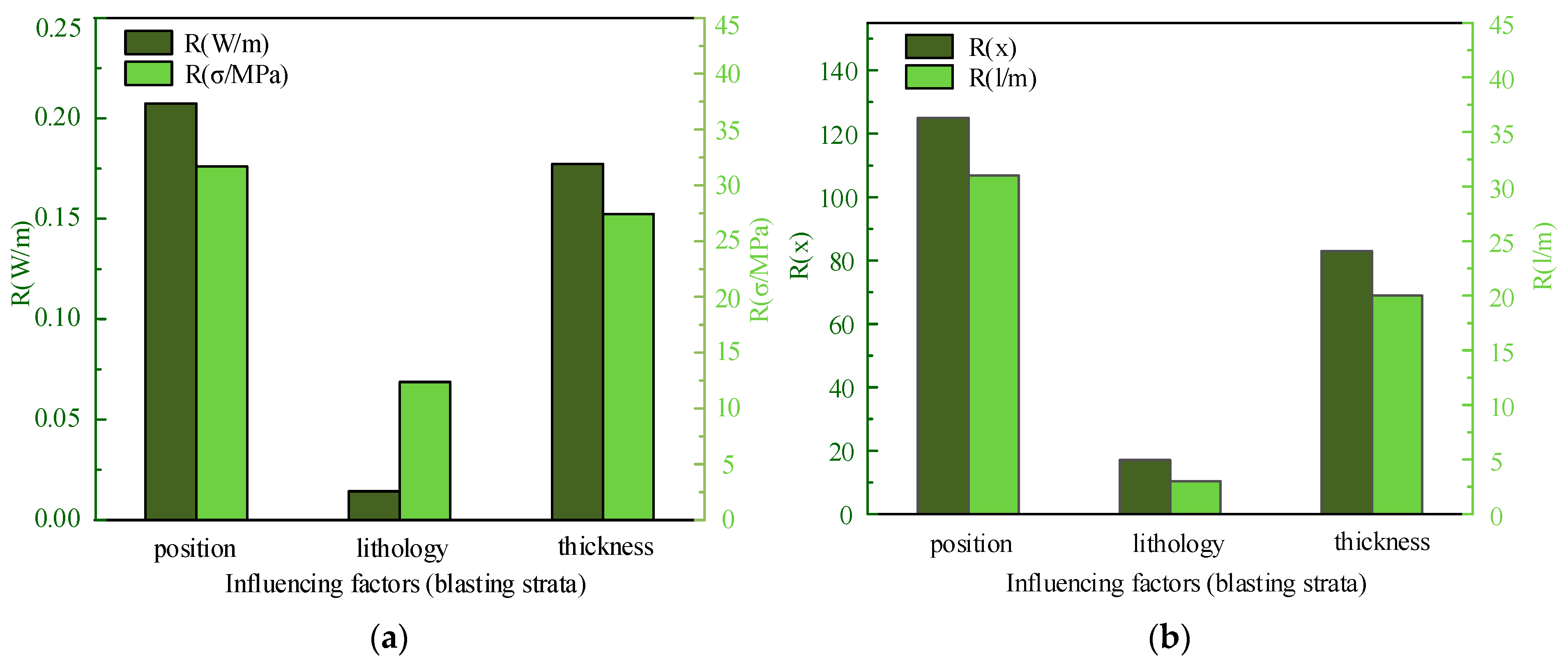
Based on the above four simulation schemes, the maximum stress value and the maximum value of overburden subsidence were obtained, as shown in Table 4 of Section 4.1, and a range calculation and comparison diagram was drawn according based on the orthogonal test results. As shown in Figure 9, by comparing the range of the subsidence value W, the maximum stress value σ, the number of cracks x, and the length of cracks l under different levels, the influence degree of each factor on the maximum stress and the maximum subsidence value of overburden rock could be ranked as follows: blasting layer position → blasting rock thickness → blasting rock lithology. Therefore, for long-distance drilling and blasting under the condition of a high roof, the selection of the blasting layer the factor which has the greatest influence on the control of stress and subsidence change in the overburden rock.
Through the above analysis, it can be seen that the selection of blasting layer position should be given priority when long-distance drilling blasting is used for pressure relief in the prevention and control of middle and high roof rock bursts.

5. Blasting Scheme Design and Effect Evaluation

5.1. Selection of Pressure Relief Layer

Based on the above analysis, the design of a long-distance drilling blasting implementation plan needs to consider the selection of appropriate blasting layers. Therefore, we created a comprehensive drilling histogram and applied the coal mine overlying rock main control induced disaster layer identification engineering technology method [39], using the following formula to determine the Ess rate of change R:
R = (Ess1Ess2)/Ess1
In the formula, Ess is the sum of squared errors.
E s s = i = 1 K x j i Z i x j i w i 2
where K is the number of clusters, x j i is the identification parameter of the disaster-causing key layer of the j th layer in the i th cluster, wi is the centroid of the identification parameter set of the i th cluster, and Zi is the identification parameter set of the disaster-causing key layer corresponding to the i th cluster.
Next, threshold R0 with a significant decrease of Ess was assessed. According to the change of Ess, the K′ value of the ‘elbow’ point was measured, and the difference between different clusters could be calculated to identify homogeneous parameter Ti.
T i = 1 D i x j i Z i x j i
where Di is the number of key layers in the cluster when the i th cluster is clustered.
Combined with the identification basis of the main control and disaster-causing horizon of the roof overburden of the working face [39] and the key stratum discrimination theory [40,41], the blasting horizon was identified as 52~67 m above the coal seam of the 2412 working face. According to the measured drilling information, this horizon presents a siltstone lithology.

5.2. Long Distance Drilling Arrangement

According to the periodic weighting interval during the mining period of the working face and the fracture development radius of the blasting surrounding rock, the hole spacing was determined, so that the rock breaking distance after blasting was reduced by half. As such, the following formula was obtained:
dhlr/2 + 2rf
where dh is the distance between the long-distance drilling blasting holes, lr is the periodic weighting interval, and rf is the fracture development radius.
Through the actual drilling and peeping results of the mine site, the crack propagation radius of sandstone with a compressive strength of 90 MPa was 5 m. Combined with the field measured compressive strength of the sandstone and field experience with the 2412 working face, the blasting hole spacing was finally set at 30 m.
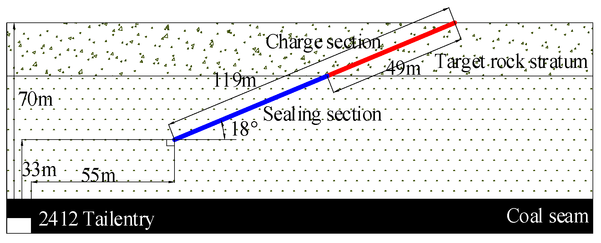
Finally, a blasting hole with an angle of 90° relative to the horizontal direction was used as the main hole, and the fan-shaped blasting holes were arranged on both sides to ensure that the position of the final hole was aligned in a straight line and the connection formed a square or approximate square. Finally, based on the above principles, the angle of the rotation space was determined to be 7~17°, the corresponding hole depth was 82~164 m, and the drilling inclination angle was 12~20°. The actual drilling plane blasting area is shown in Figure 10. Taking one of the drillings as an example, a drilling construction drawing is shown in Figure 11.
A total of 18 long-distance blasting drillings were implemented, with a total drilling footage of 2209 m and a total explosive consumption of 2.6 t.

5.3. Evaluation of the Pressure Relief Effect of Long-Distance Drilling Blasting

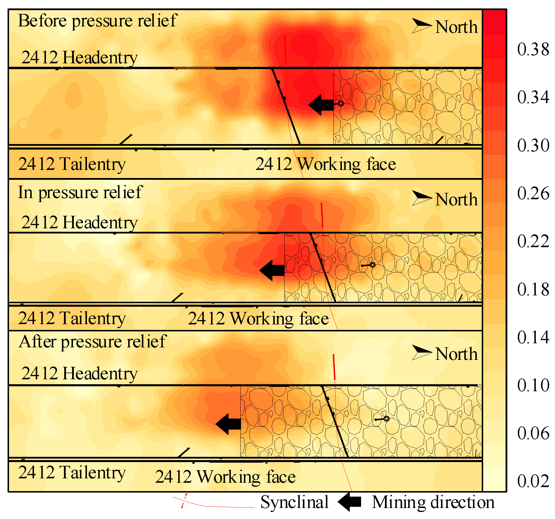
Since mining of the 2412 working face began in April 2023, the process has been divided into two stages according to the pressure relief methods in different areas. The first stage was the roof deep hole blasting mining stage, and the second stage was the long-distance drilling blasting mining stage. Micro seismic activity reflects the characteristics of micro seismic activity in a certain period of time in a certain area. A distribution cloud diagram of micro seismic activity before and after pressure relief of long-distance drilling blasting was selected for analysis to evaluate the pressure relief effect of long-distance drilling blasting. The time span of each stage was two months, allowing us to evaluate the pressure relief effect of long-distance drilling blasting.
According to Figure 12, during the mining period of the working face, the micro seismic activity in front of the mining area was high, and the micro seismic energy in front of the mining area was relatively concentrated. By comparing the micro seismic activity cloud maps of the three stages of long-distance drilling blasting and roof deep hole blasting before and after the implementation of long-distance drilling blasting, it can be seen that in the initial roof deep hole blasting stage, the micro seismic activity index in front of the mining area reached 0.5. After the implementation of long-distance drilling blasting pressure relief, the activity was significantly reduced, indicating that after long-distance drilling blasting, the energy had been released in time to reduce the rock burst danger caused by the accumulation of a large amount of energy in the roof strata.
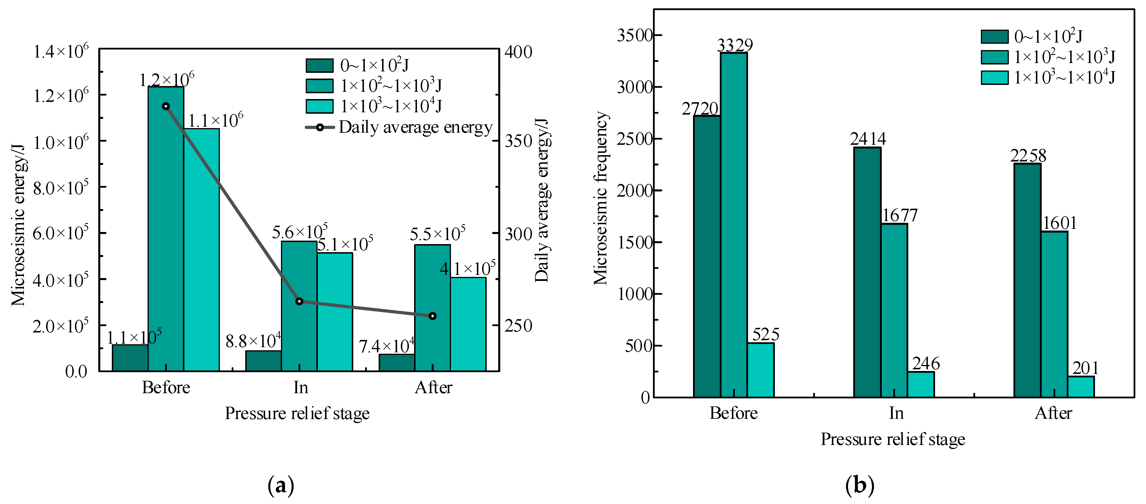
Finally, according to the measured micro seismic data, a comparison diagram of energy and frequency changes of micro seismic events before and after long-distance drilling blasting was drawn, as shown in Figure 13.
According to Figure 13, after the implementation of long-distance drilling blasting, the frequency and energy of micro seismic events showed a significant downward trend. The daily average energy was reduced from 370 J to 250 J. The energy of events with micro seismic energy between 1.0 × 10² J and 1.0 × 10⁴ J was greatly reduced after the implementation of long-distance drilling blasting pressure relief. The frequency of micro seismic events with energy between 1.0 × 10³ J and 1.0 × 10⁴ J was reduced by 61.7% after the implementation of long-distance drilling blasting pressure relief, and there was no event with micro seismic energy greater than 104 J, indicating that long-distance drilling blasting effectively reduces the accumulation of large energy events. The energy was released in time to minimize the risk of rock bursts caused by sudden releases.
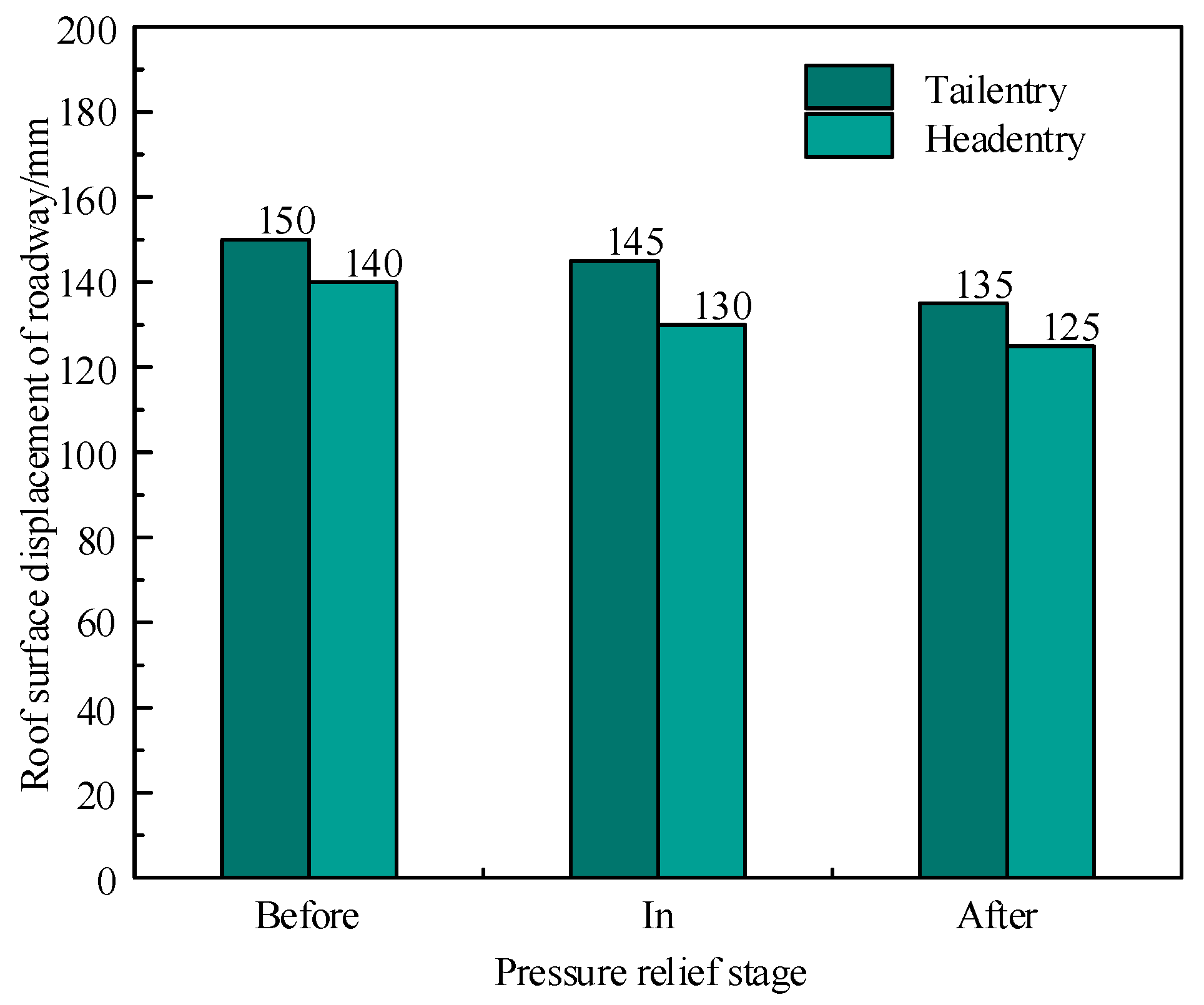
According to the measured data of the roof displacement of the two entries in the working face before and after the implementation of long-distance drilling blasting, the average values of the roof surface displacement in the three stages were compared, and the displacement changes were drawn, as shown in Figure 14. According to the figure, after the implementation of long-distance drilling and blasting, the displacement of the roof surface of the return airway and the transportation entry was reduced by 15 mm before the measures were taken, indicating that long-distance drilling and blasting effectively reduced the deformation of the entry and avoided the entry itself. The roof caused a greater degree of damage and ensured the safe mining of the working face.

6. Conclusions

In this paper, through numerical simulation, theoretical analysis, and other research methods, the load reduction mechanism of long-distance borehole blasting was analyzed, and the effect of this method was verified based on field practice. The research conclusions are as follows:
(1)
Common blasting pressure relief has the limitations of a small pressure relief range and suitability only for low roof treatment. Long-distance drilling blasting pressure relief is arranged by arranging the high-level drilling field above the coal seam, and the long-distance drilling is arranged in a fan-shaped distribution, which effectively pre-splits the whole overburden rock;
(2)
Based on existing research, the influence of three factors, i.e., blasting the pre-splitting layer, blasting rock thickness, and blasting rock lithology, on the pressure relief effect of long-distance drilling blasting in practical applications, e.g., a working face, is analyzed, and an orthogonal test was designed. Based on the actual drilling information of the working face, a UDEC numerical model was established to analyze the overburden subsidence, stress change, and rock fracture. Taking Scheme 1 as an example, it was found that after long-distance drilling and blasting, the average value of overburden subsidence increased by 21.2%, the maximum value increased by 15.2%, the average stress value decreased by 22.8%, and the maximum stress value decreased by 34%. The orthogonal test results showed that the weight ratio of the blasting effect was as follows: blasting layer position → blasting rock thickness → blasting rock lithology;
(3)
Combined with our analysis of the factor weight ratio, the selection of a blasting horizon should be given priority in the design of a long-distance drilling blasting implementation scheme. Combined with actual drilling information, the roof above the 2412 working face was set as the blasting horizon at about 52–67 m. According to our analysis of measured micro seismic data, long-distance drilling blasting can effectively reduce the frequency of micro seismic energy and events, reduce the spatial activity of the working face, avoid the influence of a high roof on the mining period of a working face from the source, release energy over time, avoid the accumulation of large energy events, and reduce the risk of rock burst.

Author Contributions

Conception and design of experiment, Q.G.; provision of ideas and proposal, A.C.; manuscript writing, W.Z. and Q.G.; use of simulation software, Y.Y.; data and graph processing, C.X. and Q.H.; project administration and funding acquisition, A.C. All authors have read and agreed to the published version of the manuscript.

Funding

This research was funded by the National Natural Science Foundation of China (52274098, U21A20110), National Key Research and Development Program (2022YFC3004603) and Jiangsu Province International Collaboration Program-Key National Industrial Technology Research and Development Cooperation Projects (BZ2023050).

Institutional Review Board Statement

Not applicable.

Informed Consent Statement

Not applicable.

Data Availability Statement

The data used to support the findings of this study are available from the corresponding author upon request.

Acknowledgments

The authors are grateful to the coal mine for providing field data. The authors would also like to thank the peer reviewers and editors for their valuable comments and suggestions.

Conflicts of Interest

The authors declare no conflicts of interest.

References

  1. Zhang, J.; Huang, S.; Wang, H.; Wang, H.; Zhou, N.; Deng, X. Research progress of multi-disaster coordinated prevention and control technology for coal seams with an extra-thick water-bearing sandstone roof. J. Min. Saf. Eng. 2025, 42, 1–15. [Google Scholar]
  2. Wang, G.; Pan, Y.; Zhao, S.; Pang, Y.; He, Y.; Wei, W. How to realize safe-efficient-intelligent mining of rock burst coal seam. Coal Sci. Technol. 2024, 52, 1–14. [Google Scholar]
  3. Zhong, T.; Song, Y.; Liu, J. Pattern, hange and new situation of coal mine rock burst prevention and control in China. Chin. J. Rock Mech. Eng. 2023, 42, 2081–2095. [Google Scholar]
  4. Pan, J.; Xia, Y.; Wang, S.; Ma, W.; Zhang, C.; Wang, B. Technical difficulties and emerging development directions of deep rock burst prevention in China. J. China Coal Soc. 2024, 49, 1291–1302. [Google Scholar]
  5. Wu, J.; Pan, J.; Feng, M.; Lu, C.; Gao, J.; Yan, Y.; Ma, H. Study on the response characteristics of overlying rock mining with different levels of fracturing in different areas of the roof. J. China Coal Soc. 2024, 49, 4351–4364. [Google Scholar]
  6. Zhu, S.; Zhang, X.; Jiang, F.; Ma, J.; Zhang, X.; Xia, K.; Wang, C.; Li, S.; Liu, J.; Zhu, Q.; et al. Mechanism and application of energy release modification of coal pillar in high stress entry in deep well. J. China Coal Soc. 2024, 49, 3711–3727. [Google Scholar]
  7. Zhu, S.; Liu, J.; Jiang, F.; Shang, X.; Sun, X.; Zhang, X.; Song, D.; Zhang, M.; Wang, A.; Xie, H.; et al. Classification, prediction, prevention and control of roof movement type mine earthquake and induced disasters in China’s coal mines. J. China Coal Soc. 2022, 47, 807–816. [Google Scholar]
  8. Sun, W.; Wang, Z.; Li, Q.; Wang, W.; Cao, P.; Xu, H. Multiple synergistic control technology of rock burst disasters in deep hard roof working faces. Chin. J. Rock Mech. Eng. 2024, 43, 1736–1750. [Google Scholar]
  9. Mu, Z.; Dou, L.; Zhang, G.; Zhang, S.; Li, Z.; Zhang, J. Study of prevention methods of rock burst disaster caused by hard rock roof. J. China Univ. Min. Technol. 2006, 35, 737–741. [Google Scholar]
  10. Hall, A.; Simser, B.; Cai, M.; Lindsay, J. Preconditioning blasting for rockburst control in a deep shaft sink. Int. J. Rock Mech. Min. Sci. 2024, 181, 105841. [Google Scholar] [CrossRef]
  11. Tang, B. Rockburst Control Using Destress Blasting. Ph.D. Thesis, McGill University, Montréal, QC, Canada, 2000. [Google Scholar]
  12. Vennes, I.; Mitri, H.; Chinnasane, D.R.; Yao, M. Large-scale destress blasting for seismicity control in hard rock mines: A case study. Int. J. Min. Sci. Technol. 2020, 30, 141–149. [Google Scholar] [CrossRef]
  13. Zhang, J.; Dong, X.; Bai, J.; Jia, L. The mechanism and prevention of rock burst induced by the instability of the composite hard-roof coal structure and roof fractures. Eng. Fract. Mech. 2024, 310, 110512. [Google Scholar] [CrossRef]
  14. Lv, H.; Cheng, Z.; Xie, F.; Pan, J.; Liu, F. Study on hydraulic fracturing prevention and control of rock burst in roof of deep extra-thick coal seam entry group. Sci. Rep. 2024, 14, 29537. [Google Scholar] [CrossRef] [PubMed]
  15. Dai, X.; Gao, R.; Gao, W.; Bai, D.; Huang, X. Exploring the Distribution Characteristics of High Static Load in the Island Working Face of Extra-Thick Coal Seams with Hard Roof: Addressing the Challenge of Rock burst Risk. Appl. Sci. 2024, 14, 1961. [Google Scholar] [CrossRef]
  16. Yang, S.; Bian, J.; Liu, A.; Li, X.; Li, F.; Ma, X.; Gong, S. Comparative Study on the Prevention and Control Effects of Rock burst Between Hydraulic Fracturing Sections and Blank Sections. Sensors 2024, 24, 7281. [Google Scholar] [CrossRef]
  17. Cheng, L.; Zhang, Z.; Jiang, P.; Yang, J. Research and application of stress field response mechanism based on roof hydraulic fracturing pressure relief. J. Min. Saf. Eng. 2023, 40, 722–729. [Google Scholar]
  18. Zhao, S.; Ouyang, Z.; Liu, J.; Zhang, G.; Wang, Y.; Li, X. Theory and application of prevention of rock burst by advanced deep hole roof blasting. Chin. J. Rock Mech. Eng. 2013, 32 (Suppl. S2), 3768–3775. [Google Scholar]
  19. Lv, R.; Li, J.; Zhu, L.; Wang, C.; Quan, X.; Ni, X.; Wang, B.; Zhang, S. Study on the technology of acid pressure relief and coal burst reduction in surface wells with extremely thick conglomerate roof. Coal Sci. Technol. 2025. Available online: http://kns.cnki.net/kcms/detail/11.2402.TD.20241021.1103.001.html (accessed on 1 June 2024).
  20. Zheng, K.; Yuan, L.; Zhang, P.; Wang, L. Rock bursts induced by thick-hard roof with compound key strata: Mechanisms and technical modes for prevention. Coal Geol. Explor. 2024, 52, 14–24. [Google Scholar]
  21. Fu, B.; Gao, M.; Tu, M.; Zhang, P. Composite effect of key stratum and its influence on strata behaviors. J. Min. Saf. Eng. 2016, 33, 220–225. [Google Scholar]
  22. Lai, X.; Zhu, H.; Guo, Z.; Gu, H.; Li, X.; Zhao, Q.; Shan, P. Breaking dynamic load mechanism and application of high key strata in gully area of shallow coal seam. J. Min. Saf. Eng. 2024, 41, 879–888. [Google Scholar]
  23. Jiao, W.; Ma, W.; Shang, N.; Si, L.; Ma, J.; Wang, Y. Directional deep hole hydraulic fracturing pressure relief and erosion prevention technology in hard roof of extra-thick coal seam. Coal Technol. 2024, 43, 213–216. [Google Scholar]
  24. Wang, S.; Zhi, B.; Du, T.; Yang, G.; Lu, C.; Xia, Y. Ground fracturing pre-control technology for potential mine seismic risk of thick and hard roof. Coal Sci. Technol. 2023, 51, 1–11. [Google Scholar]
  25. Fan, J.; Dou, L.; He, H.; Du, T.; Zhang, S.; Gui, B.; Sun, X. Directional hydraulic fracturing to control hard-roof rock burst in coal mines. Int. J. Min. Sci. Technol. 2012, 22, 177–181. [Google Scholar] [CrossRef]
  26. Zhuang, J.; Mu, Z.; Cai, W.; He, H.; Hosking, L.J.; Xi, G.; Jiao, B. Multistage hydraulic fracturing of a horizontal well for hard roof related coal burst control: Insights from numerical modelling to field application. Int. J. Min. Sci. Technol. 2024, 34, 1095–1114. [Google Scholar] [CrossRef]
  27. Yu, B.; Peng, M.; Tai, Y.; Guo, S. Assessment and control of the mine tremor disaster induced by the energy accumulation and dispersion of thick-hard roofs. Int. J. Min. Sci. Technol. 2024, 34, 925–941. [Google Scholar] [CrossRef]
  28. Pan, J.; Lu, C.; Ma, X.; Xia, Y.; Xie, F.; Xu, G.; Dou, G.; Lv, D.; Sun, X.; Ma, W. System and application of regional fracking of coal seam roof on and under the ground to prevent rock burst. Coal Sci. Technol. 2023, 51, 106–115. [Google Scholar]
  29. Pan, J.; Kang, H.; Yan, Y.; Ma, X.; Ma, W.; Lu, C.; Lv, D.; Xu, G.; Feng, M.; Xia, Y.; et al. The method, mechanism and application of preventing rock burst by artificial liberation layer of roof. J. China Coal Soc. 2023, 48, 636–648. [Google Scholar]
  30. Hao, X.; Sun, X.; Tang, Z.; Fu, P.; Luo, J.; Shen, L.; Tang, K. Technology system and application of “Artificial Pre-Fracture Layer” by high level whole layer blasting for pressure releasing to source prevention and control of Rock burst. J. China Coal Soc. 2024, 49, 1318–1331. [Google Scholar]
  31. Zhao, Z.; Yan, R.; Cong, J. Advanced deep hole pre-splitting blasting of hard roof type and effect evaluation analysis. Coal Sci. Technol. 2023, 51, 68–76. [Google Scholar]
  32. Ma, W.; Ma, X.; Lv, D.; Wang, B.; Zhu, G. Blasting pressure relief technology for preventing rock burst in deep heading roaday. Ind. Mine Autom. 2022, 48, 119–124. [Google Scholar]
  33. Zhao, S. Mechanism and application of force-structure cooperative prevention and control on rock burst with deep hole roof pre-blasting. J. China Coal Soc. 2021, 46, 3419–3432. [Google Scholar]
  34. Brady, B.H.G.; Brown, E.T. Rock Mechanics: For Underground Mining; Springer Science & Business Media: Berlin/Heidelberg, Germany, 2006; Available online: https://www.researchgate.net/publication/49184303_Rock_Mechanics_For_Underground_Mining (accessed on 1 June 2024).
  35. Müller, L. Fundamentals of Rock Mechanics; International Centre for Mechanical Sciences: Berlin/Heidelberg, Germany, 1969. [Google Scholar]
  36. Yang, Z.; Lv, Q.; Shen, J.; Zheng, J.; Liu, J. Quantitative evaluation of rock mass basic quality index considering influence of joint surface. Chin. J. Rock Mech. Eng. 2023, 42 (Suppl. S1), 3219–3225. [Google Scholar]
  37. Pan, J.; Ma, W.; Liu, S.; Gao, J. A prevention technology of rock burst based on directional presplitting of water jet prefabricated slot in hard roof. Chin. J. Rock Mech. Eng. 2021, 40, 1591–1602. [Google Scholar]
  38. Jiao, Z.; Zhao, Y.; Jiang, Y.; Wang, H.; Lu, Z.; Wang, X. Fault damage induced by mining and its sensitivity analysis of influencing factors. J. China Coal Soc. 2017, 42 (Suppl. S1), 36–42. [Google Scholar]
  39. Ma, Y.; Zhu, S.; Pan, J.; Gao, Y.; Zhang, X.; Jiang, F.; Liu, J.; Wang, B.; Chen, Y. Identification and on-site application of the main hazard-causing stratum of overlying strata in coal mines. J. China Coal Soc. 2024, 49, 2589–2603. [Google Scholar]
  40. Xu, J.; Qian, M. Method for discriminating the location of key strata in overlying strata. J. China Univ. Min. Technol. 2000, 29, 463–467. [Google Scholar]
  41. Qian, M.; Miao, X.; Xu, J. Research on key layer theory in rock strata control. J. China Coal Soc. 1996, 2–7. Available online: https://kns.cnki.net/kcms2/article/abstract?v=YvzTZTPVeK4EYWTjHiLb4Vm_5HwIXug5EsN66x2JAhI9Sc5Zgazw7hFa7qah3umM1t5Vd4H_idOPMvWzAMzPEWrA4n60A5it9lFdeAt5NvD1tbUmBn9OWYZ92-jBvnHXPKXSx2utUOS_5g79pRYnSo72-LjIxImwJCNdTZbjNYk=&uniplatform=NZKPT&language=CHS (accessed on 1 June 2024).
Figure 1. 2412 working face layout and ZK5-3 drilling histogram.
Applsci 15 01821 g001
Figure 2. Schematic diagram of long-distance drilling and blasting.
Applsci 15 01821 g002
Figure 3. Suspended roof situation during the mining period of the working face before and after blasting. (a) No blasting. (b) After blasting.
Applsci 15 01821 g003
Figure 4. Initial model and rock block division.
Applsci 15 01821 g004
Figure 5. Cloud map of overlying rock subsidence before and after blasting. (a) No blasting. (b) After blasting.
Applsci 15 01821 g005
Figure 6. Cloud map of maximum principal stress before and after blasting. (a) No blasting. (b) After blasting.
Applsci 15 01821 g006
Figure 7. Diagram of changes in rock fissures before and after blasting. (a) No blasting. (b) After blasting.
Applsci 15 01821 g007
Figure 8. Curve of subsidence and stress value of overlying rock before and after blasting in Scheme 1. (a) The curve of overlying rock subsidence value. (b) Stress value curve.
Applsci 15 01821 g008
Figure 9. Range values of different influencing factors. (a) Overburden rock subsidence and stress. (b) Number and length of fractures.
Applsci 15 01821 g009
Figure 10. Schematic diagram of long-distance drilling and blasting area.
Applsci 15 01821 g010
Figure 11. Drilling Construction Drawing.
Applsci 15 01821 g011
Figure 12. Cloud map of activity distribution in the working face.
Applsci 15 01821 g012
Figure 13. Micro seismic changes in long-distance drilling and blasting during construction. (a) Energy. (b) Frequency.
Applsci 15 01821 g013
Figure 14. Changes in the displacement of the roof surface of the entry for long-distance drilling and blasting in construction.
Applsci 15 01821 g014
Table 1. Physical and mechanical parameters of rock blocks.
Lithologic CharactersDensity/kg·m−3Cohesion/MPaInternal Friction Angle/°
Conglomerate26705.0035
Kern stone25565.0034
Medium grained sandstone256012.1036
Fine sandstone25503.2042
Siltstone25403.7538
Mudstone26001.2032
Sandy mudstone25092.1636
Coal14601.0028
Table 2. Comparison Table of Kv and Jp.
Jp/(Strip·m−3)>3535~2020~1010~3<3
Kv<0.150.15~0.350.35~0.550.55~0.75>0.75
Table 3. Orthogonal experimental factor level table.
LevelFactors
Distance from Coal Seam/mLithology of Blasting LayerBlasting Layer Thickness/m
150Siltstone20
280Kern stone30
Table 4. Orthogonal experimental design table.
Test SchemeDistance from Coal Seam/mLithology of
Blasting Layer
Blasting Layer
Thickness/m
Overburden Rock
Subsidence W/m
Stress σ/PaFracture NumberFracture
Length/m
150Siltstone203.022.62 × 1071827162
250Kern stone302.862.23 × 1071727145
380Siltstone303.052.67 × 1071869173
480Kern stone203.252.82 × 1071935196
Disclaimer/Publisher’s Note: The statements, opinions and data contained in all publications are solely those of the individual author(s) and contributor(s) and not of MDPI and/or the editor(s). MDPI and/or the editor(s) disclaim responsibility for any injury to people or property resulting from any ideas, methods, instructions or products referred to in the content.