Article

Enhancing Continuum Robotics Accuracy Using a Particle Swarm Optimization Algorithm and Closed-Loop Wire Transmission Model for Minimally Invasive Thyroid Surgery

1
School of Computer and Communication Engineering, University of Science and Technology Beijing, Beijing 100083, China
2
Institute for Precision Medicine, Tsinghua University, Beijing 100084, China
3
Physics Department, University of Southern California, Los Angeles, CA 90007, USA
4
School of Mechanical and Electrical Engineering, Beijing Information Science and Technology University, Beijing 100192, China
5
School of Advanced Engineering, University of Science and Technology Beijing, Beijing 100083, China
*
Author to whom correspondence should be addressed.
Appl. Sci. 2025, 15(4), 2170; https://doi.org/10.3390/app15042170
Submission received: 23 January 2025 / Revised: 12 February 2025 / Accepted: 13 February 2025 / Published: 18 February 2025
(This article belongs to the Special Issue Control and Application for Biorobotics)

Abstract

:
To address the challenges of confined workspaces and high-precision requirements in thyroid surgery, this paper proposes a modular cable-driven robotic system with a hybrid rigid–continuum structure. By integrating rigid mechanisms and continuum joints within a closed-loop cable-driven framework, the system achieves a balance between flexibility in narrow spaces and operational stiffness. To tackle kinematic model inaccuracies caused by manufacturing errors, an innovative joint decoupling strategy combined with the Particle Swarm Optimization (PSO) algorithm is developed to dynamically identify and correct 19 critical parameters. Experimental results demonstrate a 37.74% average improvement in repetitive positioning accuracy and a 52% reduction in maximum absolute error. However, residual positioning errors (up to 4.53 mm) at motion boundaries highlight the need for integrating nonlinear friction compensation. The feasibility of a safety-zone-based force feedback master–slave control strategy is validated through Gazebo simulations, and a ring-grasping experiment on a surgical training platform confirms its clinical applicability.

1. Introduction

Cable-driven continuum robots are essential for achieving dexterous manipulation in minimally invasive surgical robots [1]. Minimally invasive robotic surgery systems, such as the da Vinci Surgical System [2], Versius Surgical Robotic System [3], Hugo RAS System [4], da Vinci SP Surgical System [5], SHURUI single-port robotic system [6], and Smart Endoscopic Surgical Robot System [7], are widely used in fields like gynecology [8], urology [9], hepatobiliary surgery [10], and gastrointestinal surgery [11] (Figure 1). However, their application in thyroid surgery is less common. The thyroid gland, an important endocrine organ located in the head and neck region, is the site of the most common malignant tumor [12]. Its anatomical location results in a significantly smaller and more complex surgical workspace compared to laparoscopic procedures [13]. This spatial constraint demands that robotic systems achieve exceptional flexibility for navigating confined spaces while maintaining sufficient rigidity to ensure precise instrument control—a critical requirement often unmet by traditional continuum robots. To address these dual demands, this study proposes a novel cable-driven robotic system that synergistically integrates rigid and continuum robotic mechanisms, offering a tailored solution to overcome the spatial and technical challenges inherent in robotic thyroid surgery.
Despite the potential of this hybrid design, the complex structure of the manipulator arms in minimally invasive surgical robots often incorporates several types of joints, including articulated joints, flexible continuum joints, and flexible discrete joints. This complexity results in intricate kinematic analysis. This requires sophisticated mathematical theories for theoretical analysis [14]. Commonly used kinematic analysis methods in robotics include vector analysis, Denavit–Hartenberg (D-H) parameter analysis [15], quaternion analysis [16], Lie group and Lie algebra analysis [17], and screw theory analysis [18]. However, errors inevitably occur during manufacturing and assembly processes, leading to inaccuracies in the cable-driven model parameters [19]. The accuracy of continuum robots is influenced by a variety of factors, including manufacturing errors, kinematic modeling, and the hysteresis characteristics of the tendons. However, existing research has predominantly focused on kinematic and dynamic modeling, while the exploration of the impact of manufacturing errors on the precision of continuum robots remains relatively limited [20]. This is mainly due to the difficulty in directly measuring manufacturing errors and the fact that most parameter identification methods are model-dependent, which further increases the complexity. Moreover, the coupling effects between the joints of continuum robots (as shown in Figure 2d) make parameter identification even more complex. To address this issue, this study proposes a decoupling strategy for the drive tendons between robot joints, combined with Particle Swarm Optimization (PSO) for parameter identification, to correct model errors and improve motion accuracy. Experiments have shown that this method can reduce positioning errors by 37%.

2. Methods

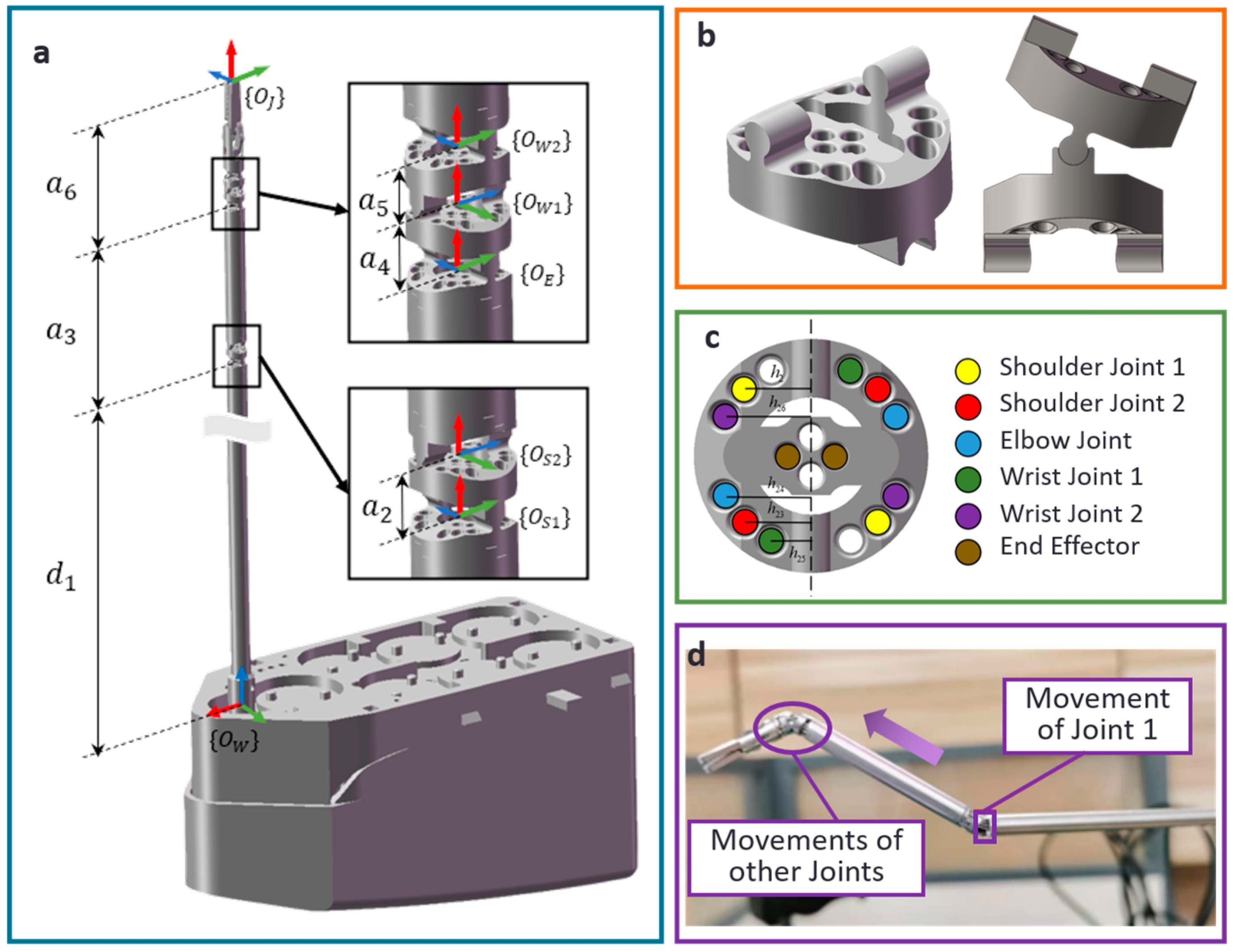
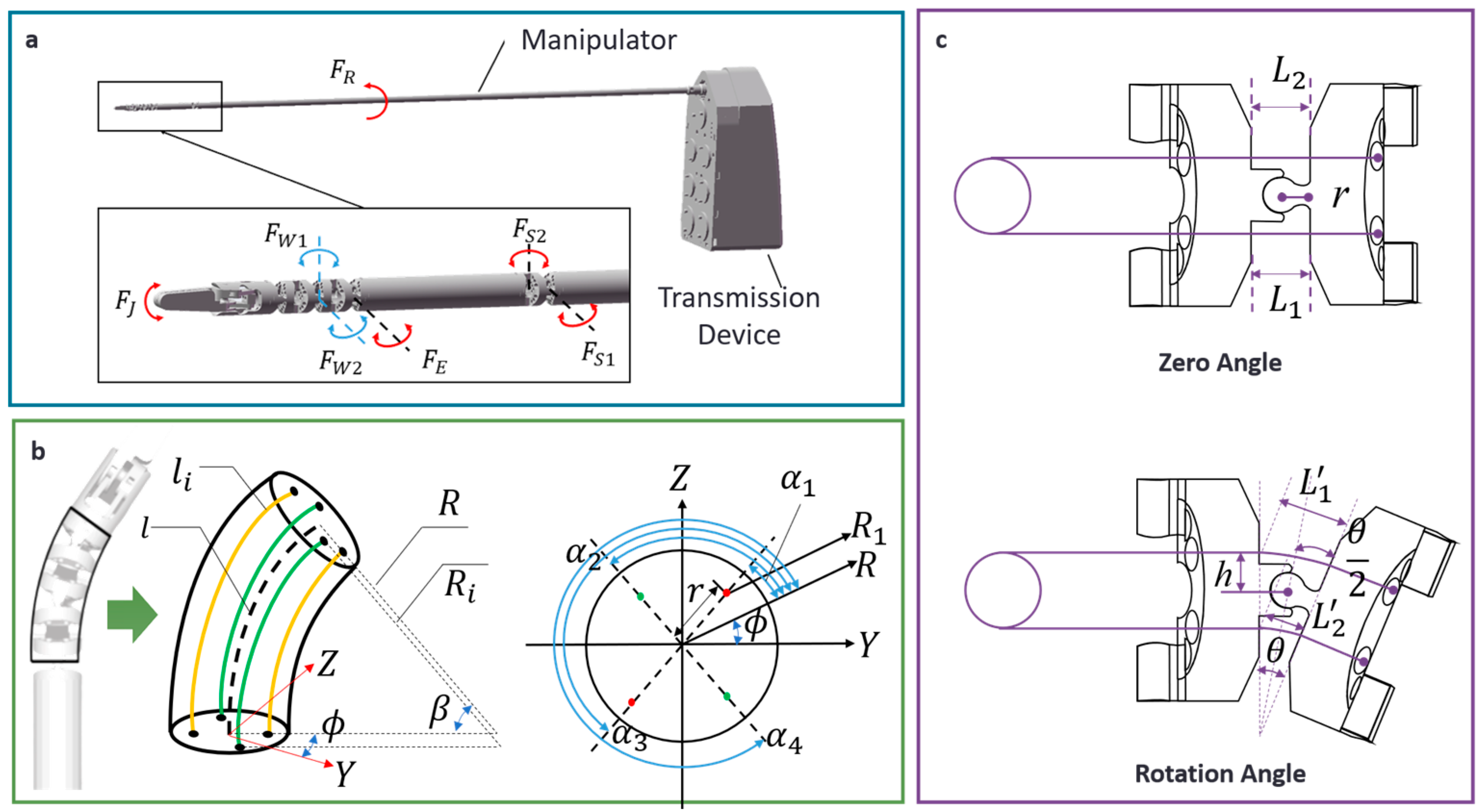
2.1. Decoupling Model for Motion of Multi-Joints

The minimally invasive thyroid surgery robot (Figure 3) features a six-degree-of-freedom arm, including rotary, shoulder, elbow, and wrist joints, driven by a combination of gear transmission and a closed-loop wire system [21].
This design mimics the structure and mobility of the human arm. The robot’s kinematic model utilizes three-space mapping theory for cable-driven technology, integrating a constant curvature model for the wrist joints and a closed-loop wire drive model for the shoulder and elbow joints (Figure 3c). This approach ensures precise control over the position and orientation of the end effector.
For the hand-driven arm utilizing wire drive technology, the driving wire will pass through multiple joints, leading to the issue of motion coupling between the joints (Figure 2d). Table 1 illustrates the relationship of motion coupling between joints. Rotation of the proximal joint affects distal joints, causing their rotation, but rotation of a joint by gear transmission does not influence other joints. Table 1 summarizes the effects of motion coupling between the joints.
According to the closed-loop wire model, if the rotation angle of the transmission wheel is θ d and the rotation radius is R , the following relationships hold:
Δ L = θ d π R 180
When the driving motor rotates clockwise, the joint also rotates clockwise. Let the clockwise rotation of the joint be defined as positive and use the rotation function sgn ( θ ) to represent the direction of joint rotation. The following relationship holds:
sgn ( θ ) = 1 , θ > 0 0 , θ = 0 1 , θ < 0
As shown in Figure 2c, when shoulder 1 (joint 2) rotates by an angle θ 2 , the remaining distal joints exhibit coupled motion. The variation in the drive wire length for the i-th joint, as well as the coupled drive wire length variation from the i-th joint to the j-th joint, can be expressed as follows:
Δ L d i i = 2 h i sin ( θ i / 2 ) + sgn ( θ i ) ( 2 r 2 r cos ( θ i / 2 ) )
Δ L 2 j = 2 h i j sin ( θ i / 2 ) + sgn ( θ i ) ( 2 r 2 r cos ( θ i / 2 ) ) , ( j = 3 , 4 , 5 , 6 )
Let the joint angle vector θ = [ θ 1 , θ 2 , θ 3 , θ 4 , θ 5 , θ 6 ] T represent the angular change of each joint and the driving angle vector θ d = [ θ d 1 , θ d 2 , θ d 3 , θ d 4 , θ d 5 , θ d 6 ] T represent the angular change of each reducer motor. The vector of steel wire length variation, Δ L = [ 0 , Δ L d 2 , Δ L d 3 , Δ L d 4 , Δ L d 5 , Δ L d 6 ] T , corresponds to the change in steel wire length for each joint. The relationship between the joint angle can be described by the following equation:
θ d 1 Δ L d 2 Δ L d 3 Δ L d 4 Δ L d 5 Δ L d 6 = d D 0 0 0 0 0 0 Δ L d 22 θ 2 0 0 0 0 0 Δ L 23 θ 2 Δ L d 33 θ 3 0 0 0 0 Δ L 24 θ 2 Δ L 34 θ 3 Δ L d 44 θ 4 0 0 0 Δ L 25 θ 2 Δ L 35 θ 3 Δ L 45 θ 4 Δ L d 55 θ 5 0 0 Δ L 26 θ 2 Δ L 36 θ 3 Δ L d 46 θ 4 Δ L d 56 θ 5 Δ L d 66 θ 6 θ 1 θ 2 θ 3 θ 4 θ 5 θ 6
The relationship between the joint angle and the driving motor angle is as follows:
θ d 1 = d D θ 1 , θ d i = 180 π R Δ L d i ( i = 2 , 3 , 4 , 5 , 6 )

2.2. Inverse Kinematics Solution Based on SOP

Inverse kinematics in robotics refers to a computational approach used to determine the joint angles or displacements necessary for an end-effector to achieve a specified position and orientation. Common methods for solving inverse kinematics include the analytical method [22], numerical methods [23], optimization-based methods [24], machine learning methods [25], and sampling-based methods [26]. As previously detailed in our work [21], the Sequential Quadratic Programming (SQP) algorithm [27] is employed.
The objective function for the SQP algorithm is formulated as the sum of the absolute values of the position and orientation errors between the desired pose matrix and the current pose matrix, as given below:
min θ 1 , θ 2 , θ 3 , θ 4 , β , ϕ f = e r r o r i e n t a t i o n + e r r p o s i t i o n
where e r r o r i e n t a t i o n = e r r r o l l + e r r p i t c h + e r r y a w , e r r p o s i t i o n = e r r x + e r r y + e r r z .
As demonstrated in the current study [21], a trajectory tracking simulation experiment was conducted to verify the accuracy of the inverse kinematics algorithm based on SQP. This experiment was implemented within the Robot Operating System (ROS) Melodic, running on Ubuntu 18.04, using C++. The results revealed position and orientation errors, with the maximum position error being 9.47 × 10 2 mm and the maximum orientation error being 8.82 × 10 2 degrees.

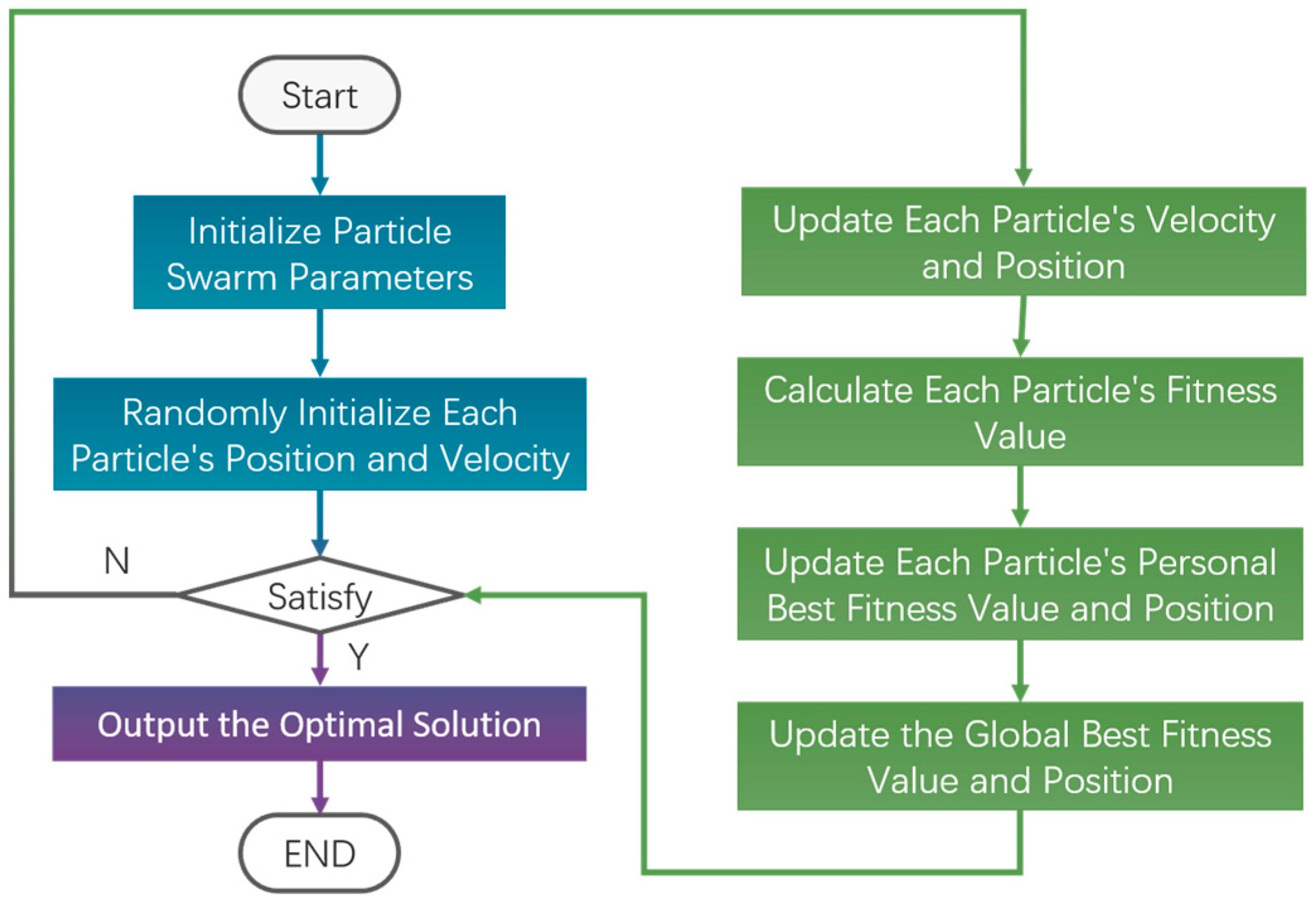
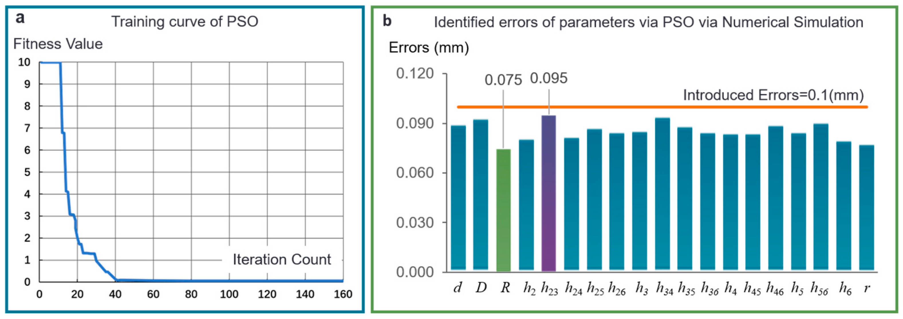
2.3. Particle Swarm Optimization Algorithm for Parameters Identification of Continuum Robots

The accuracy of the cable-driven model is critical for determining the motion control precision of the minimally invasive thyroid surgery robot. Inevitable errors introduced during the manufacturing and assembly processes can lead to inaccurate parameters in the cable-driven model. To further enhance the motion control precision of the robot, this section focuses on identifying parameter errors in the cable-driven model. By utilizing the Particle Swarm Optimization (PSO) algorithm, we aim to detect these parameter errors and apply appropriate compensation techniques, thereby improving the accuracy of the model.
The Particle Swarm Optimization (PSO) algorithm is based on the social sharing of information. Each particle has two attributes: velocity and position. The velocity dictates the particle’s movement in the search space, determining its position in the next iteration, which represents a potential solution. The PSO algorithm is governed by six key parameters. If there are N particles in a D-dimensional search space, the following parameters are defined:
(1)
The position of the i-th particle x i d and its update formulae are:
x i d = ( x i 1 , x i 2 , , x i D )
x i d k + 1 = x i d k + v i d k + 1
(2)
The velocity of the i-th particle V i d and its update formulae are:
V i d = ( v i 1 , v i 2 , , v i D )
v i d k + 1 = w v i d k + c 1 r 1 ( p i d , p b e s t k x i d k ) + c 2 r 2 ( p d , g b e s t k x i d k )
In Equation (11), w represents the inertia weight, c 1 and c 2 are the self-learning and global learning factors of the particles, respectively, and r 1 and r 2 are random numbers between 0 and 1.
(3)
The individual optimal solution for the d-th dimension of the i-th particle at the k-th iteration, denoted P i d , p b e s t is
P i d , p b e s t = ( p i 1 , p i 2 , p i D )
(4)
The group optimal solution for the d-th dimension at the k-th iteration P d , g b e s t is
P d , g b e s t = ( p 1 , g b e s t , p 2 , g b e s t , , p D , g b e s t ) .
(5)
The fitness value of the optimal position found by the i-th particle is f p .
(6)
The fitness value of the optimal position found by the swarm is f g .
Here, N represents the number of particles used to solve the problem. When N is small, the swarm may fall into a local optimum. However, as N increases, convergence improves, and the global optimal solution is more easily found. Nonetheless, the computational effort required for each iteration increases, and beyond a certain point, increasing N does not yield significant improvements. The dimension D of the search space in the Particle Swarm Optimization algorithm corresponds to the number of independent variables in the solution problem. The flow of the Particle Swarm Optimization algorithm is illustrated in Figure 4.
When taking into account practical machining and assembly processes, the parameters of the cable-driven model may be subject to errors. If we define the measurement parameters from Solidworks (2022) software as P N , PSO can be applied to identify these manufacturing errors as E .
The objective function is designed as follows:
min f = i = 1 6 θ d i N θ d i R
where θ d i N represents the driving motor angles obtained from the cable-driven model, which considers parameter errors identified by PSO, and θ d i R denotes the actual driving motor angle.
As the cable-driven model expressed in Equation (6) contains 19 parameters (d, D, R, h2, h23, h24, h25, h26, h3, h34, h35, h36, h4, h45, h46, h5, h56, h6, r ), the dimension of the search space of PSO is 19. The inputs to PSO are the theoretical values of these 19 parameters, and the outputs of PSO are their identified errors. The smaller the value of the objective function, the closer the robot parameters are to the actual values after parameter identification.

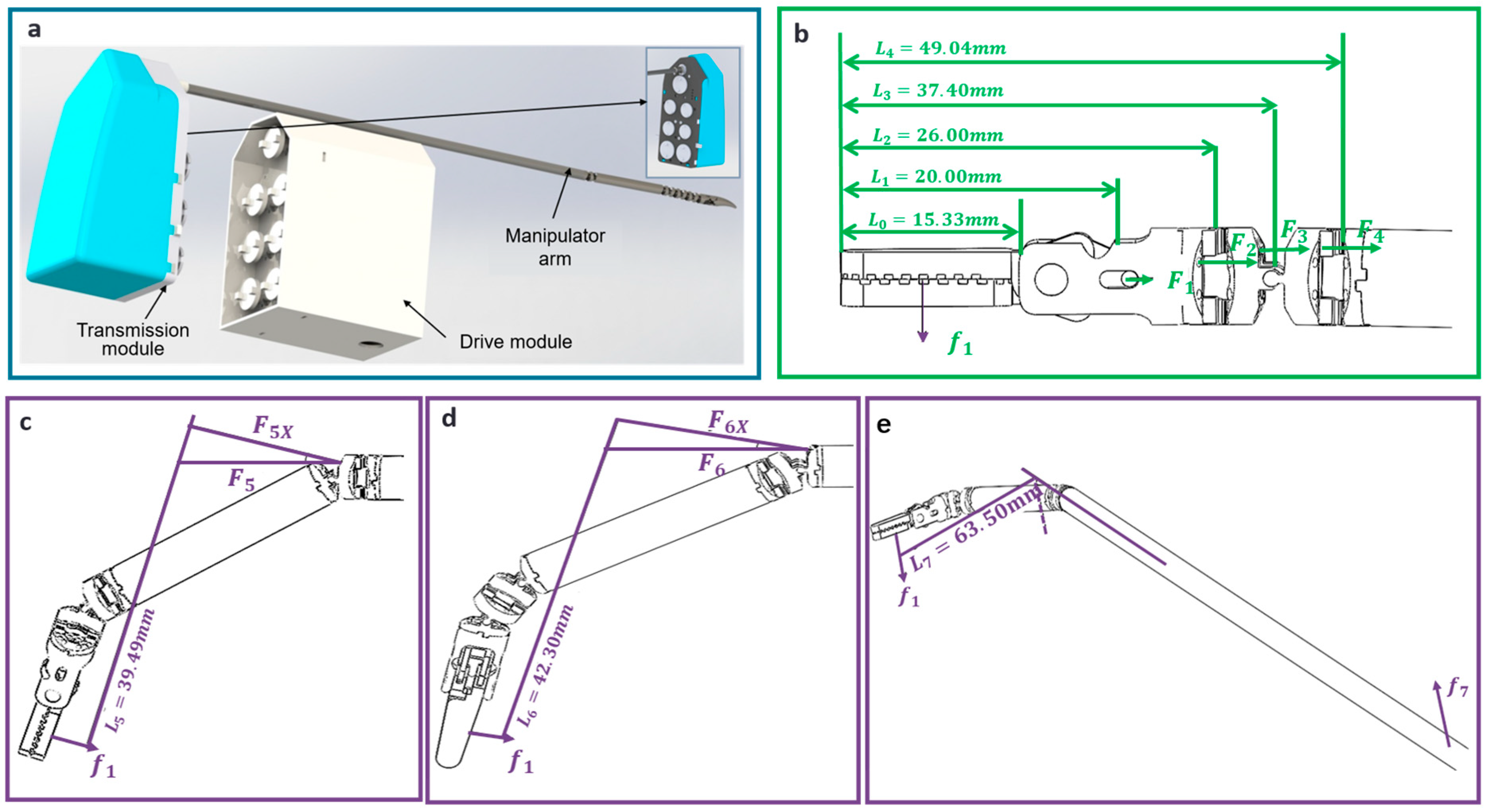
2.4. Robotic System for Thyroid Surgery

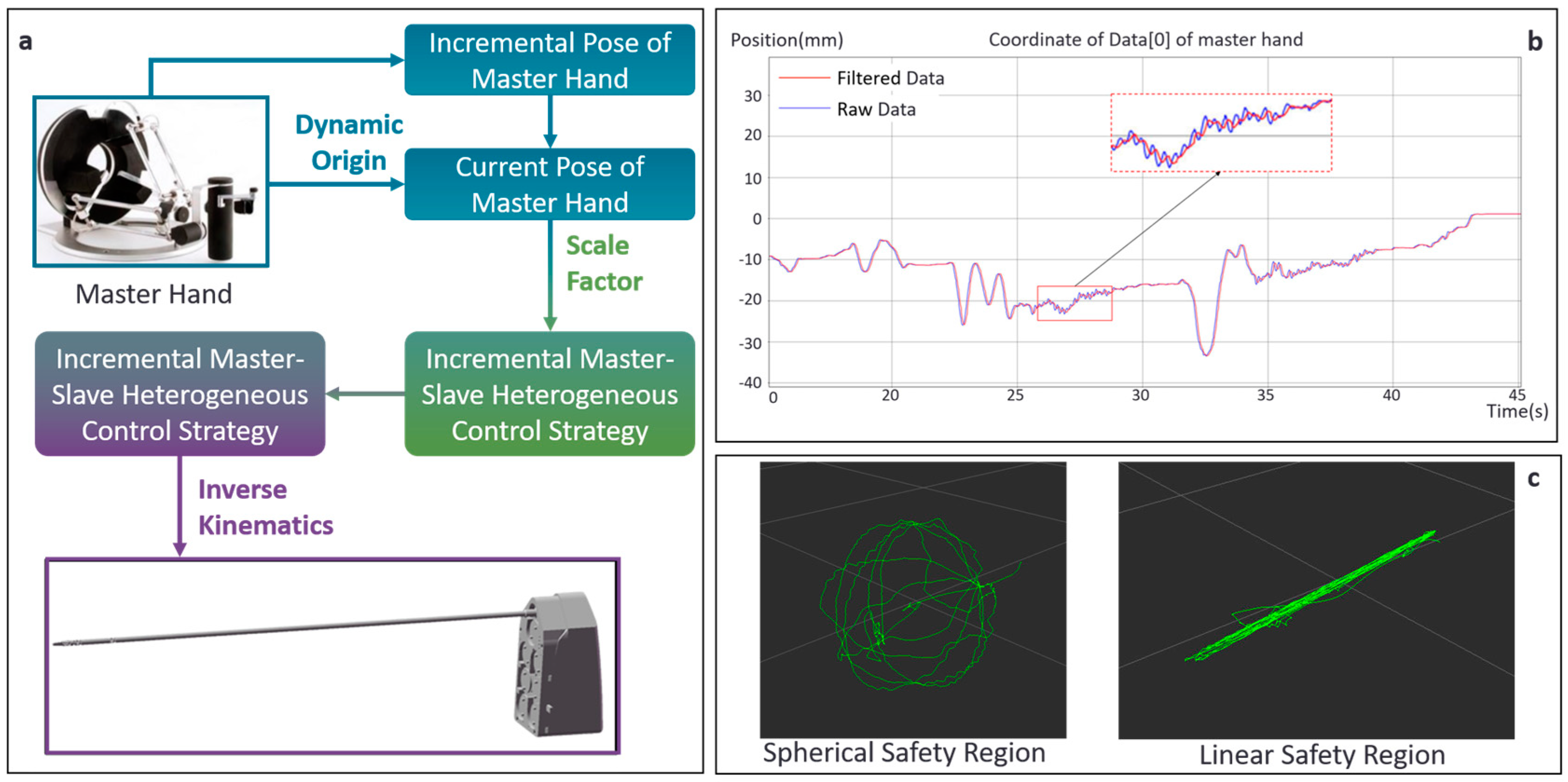
2.4.1. Master–Slave Control System for Thyroid Surgery

In consideration of surgical safety, the proposed thyroid surgical robot adopts a master–slave control paradigm, allowing the surgeon to precisely control the robotic arm’s movements through a master console. The master device used in this study is the Omega.7, manufactured by Force Dimension. The master device and the slave arm have different structures and operate within a master–slave framework. Since the base coordinates of the master device and the slave arm do not coincide and their workspaces are not identical, an incremental mapping method is necessary. This paper proposes an incremental master–slave control strategy based on Cartesian space, and its control strategy is illustrated in Figure 5a.
Thyroid tumor resection surgery requires high precision, where even the slightest hand tremors can significantly impact the accuracy of the procedure. The sampling frequency of the master device is 100 Hz, and the frequency of the surgeon’s physiological hand tremors is approximately 8–12 Hz [28]. To improve surgical precision, a second-order band-stop Butterworth filter [29] was applied to eliminate the surgeon’s hand tremors. The transfer function of the Butterworth filter in the discrete-time domain is given by:
H ( z ) = b 0 + b 1 z ( 1 ) + b 2 z ( 2 ) a 0 + a 1 z ( 1 ) + a 2 z ( 2 )
where a i and b i are coefficients of the filter. Their values are as follows: a 0 = 1 , a 1 = 1.45 , a 2 = 0.78 ; b 0 = 0.89 , a 1 = 1.45 , a 2 = 0.89 .
The performance of tremor filtering for the master hand is shown in Figure 5b. The blue curve represents the original position signal of the master hand device, while the red curve shows the position signal after applying tremor filtering. The red curve exhibits smoother behavior compared to the blue curve, highlighting the effectiveness of the filtering process.

2.4.2. Drive System for the Thyroid Surgical Robot

To facilitate practical application, this paper designs a modular robotic arm drive system (Figure 6), consisting of a manipulator arm, transmission module, and drive module. The manipulator arm is integrated with the transmission module, allowing for quick assembly and disassembly (Figure 6a). The transmission module contains 7 drive shafts and 7 drive pulleys. The wires of each joint of the manipulator arm are arranged sequentially through the wire channels and drive pulleys and fixed onto the joint drive shafts. The drive module consists of 7 power transmission shafts, which control the six degrees of freedom of the manipulator arm as well as the opening and closing actions of the gripper. The drive module integrates a motor, reducer, and encoder and can be detachably assembled to the transmission module.
The total length of the surgical instrument at the end of the manipulator arm is 20.00 mm, and the diameter of the winding wheel is d = 6 mm. According to reference [30], the maximum gripping force of the surgical robot’s manipulator arm when holding patient tissue is approximately f 1 = 9 N. Considering the requirements of the surgical procedure, a safety factor needs to be incorporated. The safety factor of δ = 2 is applied. The force analysis of the surgical robot is shown in Figure 5b.
The wire tension of the manipulator arm during operation with full gripping F 1 , the tensile force of the transmission wire at the wrist joint 2 F 2 , the wrist joint 1 F 3 , and the elbow joint F 4 can be calculated as follows:
F i = f 1 × δ × ( L i L 0 2 ) d i ( i = 1 , 2 , 3 , 4 )
where d i denotes he effective winding length of the wire, L 0 = 15.33 .
Considering the angular variation of the end effector during the surgical operation, based on a deflection of θ = 20° for each joint, the tensile force of the transmission wire at shoulder 2, shoulder 1, and rotary joint for (Figure 6c–e) can be calculated as follows:
F i = f 1 × δ × L 5 d i ( i = 5 , 6 , 7 )
F i X = F 5 × cos θ ( i = 5 , 6 , 7 )
The torque of the joints controlled by the motor through the winding pulley in the transmission mechanism can be calculated as follows:
M i = F i × d 2 ( i = 1 , 2 , , 6 )
M 7 = F 7 × r 1 r 2
The gear transmission ratio is 1:2; therefore, r 1 r 2 = 2 .
According to the output functional requirements of the motors for each joint in Table 2, German FAULHABER (Schönaich, Germany) brushless DC motors (model 2232024BX4) are applied as the actuation unit.

2.4.3. Master–Slave Safety Constraints Based on Safety Zones

The minimally invasive thyroid surgery robot lacks force sensing, limiting its ability to provide feedback such as traction and pressure. As a result, surgeons rely solely on endoscopic images, which may be inadequate for precise decision-making. Moreover, the robot’s confined workspace can cause visual obstructions, increasing the risk of mis-operation and damage to healthy tissues.
To address this issue, we propose a master–slave safety constraint function, incorporating both linear and spherical safety zones.
Linear Safety Zone. This zone is used for inserting and retracting the slave tool arm. The surgeon activates the master–slave safety constraint mode by pressing a foot pedal, which locks the master hand device’s gripper at two points to define a linear path, restricting the master hand’s movement along this line.
Spherical Safety Zone. This zone defines the region of the thyroid tumor, limiting the slave tool arm to a predefined spherical area. The surgeon selects the safety zone by pressing the foot pedal twice. First, they define the center of the spherical region with the master hand device, then move to a point on the sphere’s surface and confirm by closing the gripper. If the master hand moves outside the spherical region, the system calculates the position vector to the center and applies a counteracting force using a spring-damper model to guide the master hand back within the zone.
Building upon the introduction of linear and spherical safety zones, this study further explores the implementation of a spring-damper model to enforce the safety constraints and ensure that the master hand device operates within these predefined boundaries. If the projection vector of the current position vector of the master hand device is P , and the current velocity vector of the master hand device is V , the force vector F can be calculated as follows based on the spring and damping effects:
F = K P C V
To validate the effectiveness of the master–slave safety constraints, we simulated the process of establishing spherical and linear safety zones by manipulating the master hand device and recorded the resulting trajectory of the master hand’s movement. As depicted in Figure 5c, the master hand device was confined to move exclusively within the predefined safety zones in the Gazebo simulation environment. Upon breaching these zones, a reactive force was computed utilizing the spring-damper model, which effectively propelled the master hand device back within the safe operational boundaries.

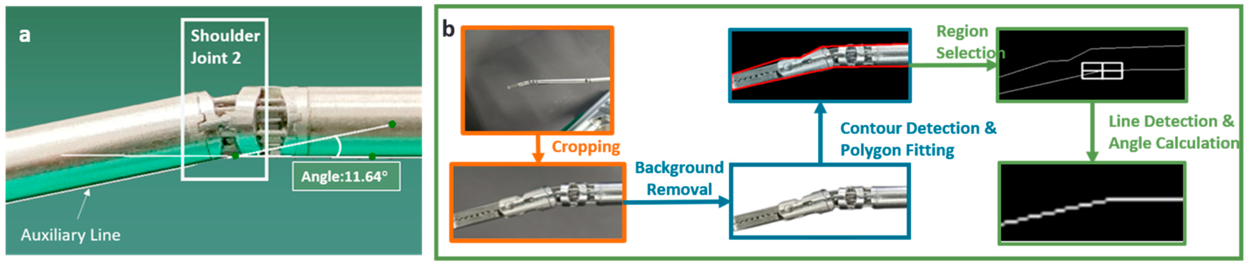
2.5. Vision-Based Measurement Technique for Angles of Joints

To identify the parameters of the robot, it is necessary to detect the angle values of each joint in the joint space. IC Measure, a manual image acquisition and measurement software, is inefficient for calculating the angles of multiple joints, as shown in Figure 7a for the shoulder joint. To address this limitation, we propose an Automatic Vision-based Measurement method (AVM) for joint angles, as shown in Figure 7b: after cropping and background removal, contours are detected using OpenCV-Python; the largest contour is then smoothed with the approxPolyDP function to reduce noise; next, a Region of Interest (ROI) is selected for angle calculation, and the Hough Transform is applied to detect lines and compute their slopes. Finally, the angles are determined using the arctangent function.

3. Experiments

3.1. Verification of Kinematic Model of Surgical Robot

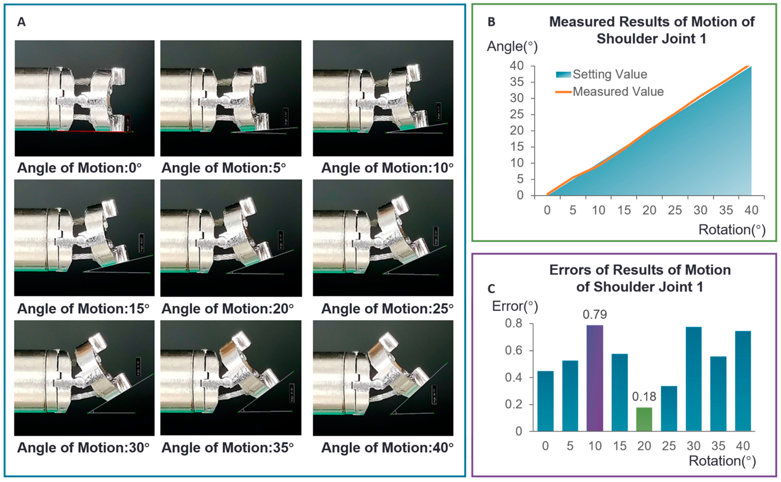
3.1.1. Accuracy Measurement Experiment for Single Joint

To assess the accuracy of the proposed single-joint closed-loop thread-driven model, experiments were conducted on shoulder joint 1 of the minimally invasive thyroid surgery robot’s manipulator arm. The camera was positioned directly above shoulder joint 1, then experiments were conducted as follows:
  • The joint was controlled to move in 5-degree increments within a range of 0 to 40 degrees.
  • Camera images were captured at each increment to record joint positions.
  • Angle measurements were obtained using the IC Measure software.
The angle measurement results for shoulder joint 1 using the IC Measure software are shown in Figure 8A. According to Table 3 and Figure 8C, the maximum absolute error in the motion of shoulder joint 1 is 0.79°, with an average error of 0.51°. Figure 8B demonstrates a strong linear correlation between the actual and theoretical motion angles of shoulder joint 1, confirming that the proposed single-joint closed-loop cable-driven model accurately describes the relationship between drive wire displacement and joint rotation.

3.1.2. Experiment for Decoupling Model for Multi-Joints

To verify the decoupling model for multi-joints operation, a series of experiments were conducted as follows: shoulder joint 1 was rotated within its specified range while the other joints were monitored for any unintended movement. Similar experiments were performed for shoulder joint 2, the elbow joint, wrist joint 1, and wrist joint 2. As shown in Figure 9, all joints moved independently without affecting each other, confirming the effectiveness of the decoupling model.

3.2. Implementation of Parameter Identification and Experiments of Repetitive Positioning Accuracy of End-Effector

3.2.1. Accuracy of Vision-Based Measurements

To assess the accuracy of the proposed vision-based measurement method, experiments were conducted on shoulder joint 1, shoulder joint 2, elbow joint, wrist joint 1, and wrist joint 2, as shown in Figure 10A. A camera was positioned above the robot arm. The visual angle measurement algorithm, alongside the IC Measure software, was employed to measure the angles of these joints. The maximum discrepancy between the visual angle measurements and the IC Measure software readings is 0.96°, which is within an acceptable margin of error.

3.2.2. Verification of Parameter Identification Algorithm

The nominal values of the thread-driven model parameters were initially obtained using SolidWorks. Artificial errors were then introduced into these parameters. Subsequently, 100 sets of joint angles were randomly selected within the joint limits of the robotic arm, serving as theoretical values. The corresponding theoretical motor angles were calculated based on these joint angles. The actual motor angles were computed using the nominal values, along with the introduced parameter errors. To identify the parameter errors, the Particle Swarm Optimization (PSO) algorithm was employed. The key parameters for the PSO algorithm were set as outlined in Table 4. The convergence curve of the fitness value over 160 iterations is presented, with convergence beginning around iteration 40. The final best fitness value achieved by the PSO algorithm was 0.074. The identified parameter errors are listed in Table 5 and Figure 11b.
Building upon the visual angle measurement method developed in Section 3.2.1, parameter errors in the cable-driven model were identified through the PSO algorithm in Section 2.3. In this study, joint angle data were collected within the range of [−40°, 40°], with a sampling interval of 5°. Specifically, 17 sets of angle data were collected for each of the following joints: rotary joint, shoulder joint 1, shoulder joint 2, elbow joint, wrist joint 1, and wrist joint 2. In total, 102 sets of data were gathered. Meanwhile, the actual rotational angles of each drive motor were recorded in real-time by the TWinCAT3 software (3.1 Build 4024) during the angle collection process. The collected joint angle data were input into the parameter identification method outlined in Section 3.2 for parameter identification analysis. Results in Table 5 showed that the error identification values were consistent with the simulation results. Then, the actual values of the kinematic model (Equation (6)) are applied in Section 3.2.3 and the application of the robot is in Section 3.3.

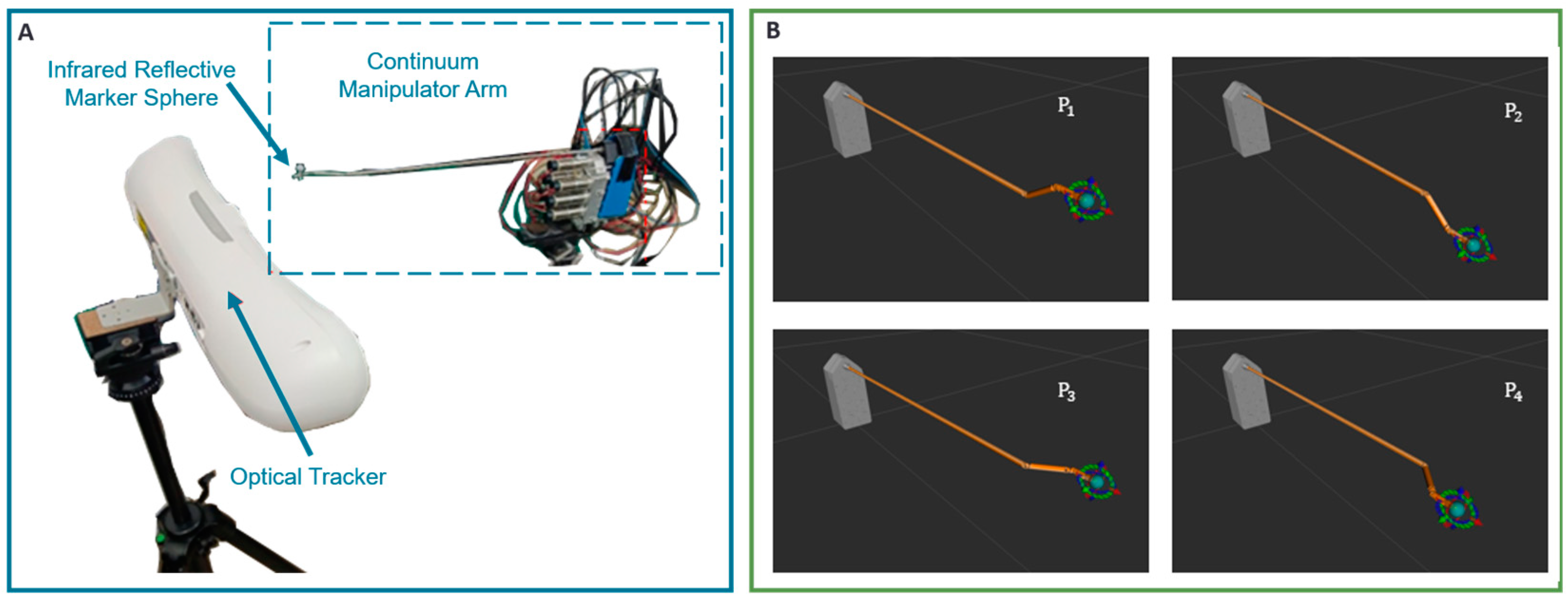
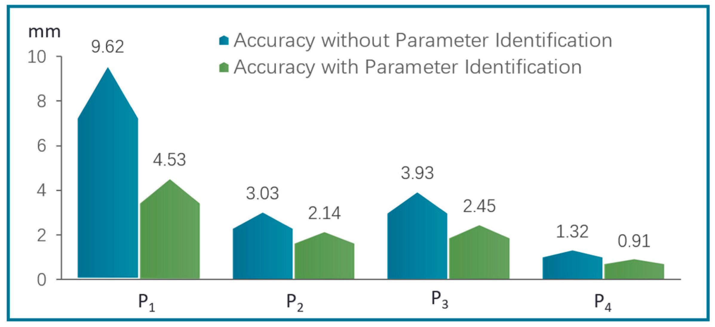
3.2.3. Experiments of Repetitive Positioning Accuracy of Continuum Robots

Repetitive positioning accuracy of the robot’s end-effector refers to the precision with which the robot can replicate its trajectory when performing the same task. This metric is a critical indicator of the robot’s precision and stability. To validate the repetitive positioning accuracy (RP) of the continuum robot, an experimental platform was established using a high-precision optical localization system, as shown in Figure 12A. We employed the AP-STD-200 optical localization system, developed by Guangzhou Aimooe Technology Co. Ltd. (Guangzhou, China), with an error margin of less than 0.12 mm.
The experiments on the repetitive positioning accuracy of the continuum robot were conducted in accordance with the GB/T 1.1—2009 standard. Four sets of measurement target points within the workspace of the slave manipulator arm were selected to cover the full range of motion: up, down, left, and right. These poses were sequentially labeled as Pose 1, Pose 2, Pose 3, and Pose 4, as shown in Figure 12B.
The master robot computer controls the slave manipulator arm to sequentially reach the four sets of target points in the following order: P1→P2→P3→P4. This procedure is repeated five times, and in each repetition, upon reaching each target point, the position parameters output by the optical navigation system’s upper-level computer application are recorded. The repetitive positioning accuracy (RP) of the end-effector of the slave manipulator arm is then calculated as follows:
R P = l ¯ + 3 S i
where S i = j = 1 n ( l j l ¯ ) 2 n 1 ,   l ¯ = 1 n j = 1 n l j ,   l j = ( x j x ¯ ) 2 + ( y j y ¯ ) 2 + ( z j z ¯ ) 2 ,   x ¯ = 1 n j = 1 n x j ,   y ¯ = 1 n j = 1 n y j ,   z ¯ = 1 n j = 1 n z j . x j , y j , z j denotes the end-effector position of the robot at the j-th instance.
The repetitive positioning accuracy of the manipulator arm, both with and without parameter identification, is illustrated in Figure 13. Before applying parameter identification, the repetitive positioning accuracy of the end-effector for the four sets of measurement target points was 9.62 mm, 3.03 mm, 3.93 mm, and 1.32 mm, respectively. After applying parameter identification to correct the robot’s kinematic parameters, the repetitive positioning accuracy of the end-effector for the same four target points improved to 4.53 mm, 2.14 mm, 2.45 mm, and 0.91 mm, respectively. These results demonstrate a significant improvement in repetitive positioning accuracy, with the overall control error reduced to within 5 mm. The repetitive positioning accuracy improved on average by approximately 1.97 mm, with an average percentage improvement in repetitive positioning accuracy of approximately 37.74%.

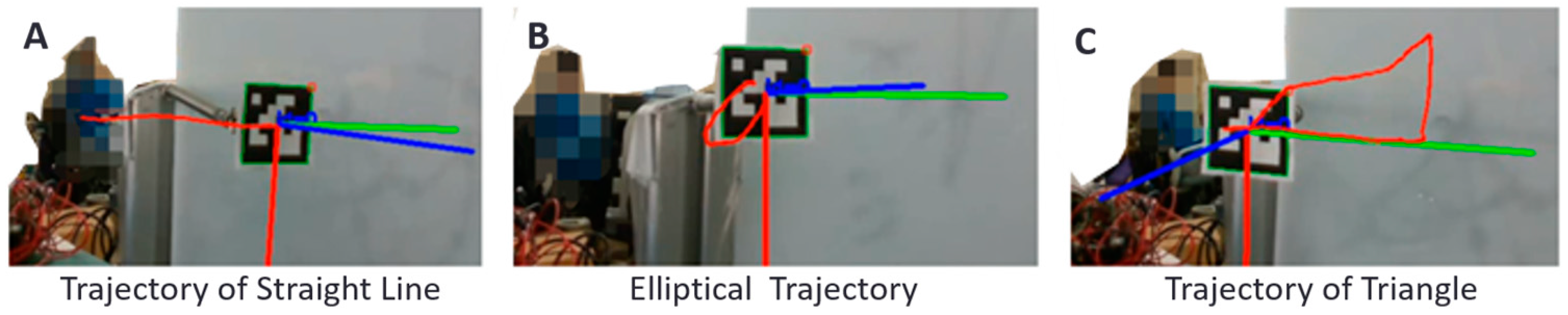
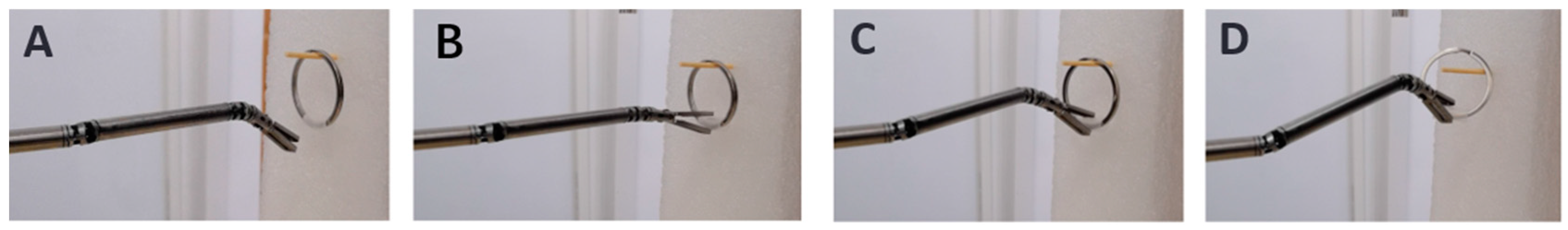
3.3. Experiments of Master–Slave Control

ArUco markers, developed by the University of Córdoba for augmented reality applications [31], were employed to track the end-effector trajectory of the robot. In these experiments, the center points of the ArUco markers were recorded, and these points were subsequently connected to form a trajectory line, as illustrated in Figure 14.
To further validate the proposed incremental master–slave control method in Cartesian space, we conducted a challenging ring-grasping experiment. In this experiment, the operator utilized the Omega.7 master device to control the slave manipulator arm in the process of grasping a ring from a cylinder. The experimental procedure is depicted in Figure 15. The operator can perform the ring-grabbing action using the hand-tool arm. This demonstrates the effectiveness of the proposed master–slave control strategy, which efficiently replicates the operator’s hand movements and meets the master–slave consistency requirement.

4. Discussion

Minimally invasive robotic surgery systems, such as the da Vinci Surgical System, have led to significant advancements across a range of surgical procedures. However, thyroid surgery presents unique challenges due to its confined workspace and the high precision required. These spatial constraints demand robotic systems that can navigate tight spaces with exceptional flexibility while maintaining the rigidity necessary for precise instrument control—a requirement often unmet by traditional continuum robots. To address these challenges, this study proposes introducing a novel robotic system designed specifically for thyroid surgery, combining a modular structure with multiple degrees of freedom (DOF) and a closed-loop cable-driven mechanism. This hybrid system offers both flexibility and rigidity, but also introduces significant kinematic analysis challenges, particularly in handling model inaccuracies caused by manufacturing and assembly errors.
Studies have shown that parameter identification can effectively solve the precision issues caused by manufacturing errors in robots [32,33,34]. However, most of these studies focus on serial robots, and research on flexible robots is relatively limited. This is mainly due to the difficulty of directly measuring manufacturing errors, as well as the fact that most parameter identification methods are model-dependent, which adds further complexity. Additionally, the coupling effects between the joints of continuum robots (as illustrated in Figure 2d) make parameter identification even more challenging.
The robot discussed in this paper combines continuum and rigid robotic elements, allowing us to apply some analysis methods typically used for rigid robots. Given this advantage, we were able to investigate the joint coupling problem and proposed a decoupling method. The experiment in Section 3.1.2 demonstrates that the proposed decoupling method is effective. Based on this, we applied a parameter identification algorithm to correct the 19 parameters of the robot’s kinematic model outlined in Section 2.1. Research in [32] indicates that the impact of different identification methods (such as genetic algorithms and Particle Swarm Optimization) on robot errors is within 2%. For continuum robots, factors like cable friction and hysteresis have a more significant impact on accuracy. Thus, we adopted the Particle Swarm Optimization (PSO) algorithm, which offers relatively better performance, for parameter identification.
Following the parameter identification scheme outlined in Section 2.3, the input data for parameter identification include the robot’s actual joint angles and motor rotation angles. The output is the robot’s model parameters. The actual motor rotation angles can be directly measured, while the predicted motor angles are calculated using Equation (6), which depends on the 19 parameters being optimized and the joint angles of the robot. The initial values of the 19 parameters were obtained using Solidworks software. Based on the value of the objective function, the Particle Swarm Optimization algorithm was used to update the parameters. Accurate measurement of the robot’s joint angles is essential for this process, which necessitates reliable measurement tools. Therefore, we introduced the vision-based joint angle measurement technique in Section 2.5. The maximum discrepancy between the visual measurements and IC Measure software readings was 0.96°, indicating that the accuracy of our algorithm is comparable to that of IC Measure. However, unlike IC Measure, our method offers the advantage of automating multi-joint measurements.
Furthermore, the decoupling of multiple joints relies on high accuracy in single-joint motion. Therefore, we conducted a single-joint accuracy experiment as described in Section 3.1.1. The maximum absolute error in the motion of shoulder joint 1 was 0.79°, with an average error of 0.51°.
Based on the above work on single-joint accuracy, multi-joint decoupling, and the validation of the measurement system’s accuracy, we performed parameter identification for the robot prototype and conducted a repetitive positioning accuracy verification experiment. The results indicated that, after parameter identification, the robot’s repetitive positioning accuracy improved by an average of 1.97 mm, with a percentage improvement of approximately 37.74%.
During the accuracy measurement, we measured the accuracy of four target points. For points P2, P3, and P4, the accuracy before and after parameter identification was 3.03 mm, 3.93 mm, and 1.32 mm, respectively, and 2.14 mm, 2.45 mm, and 0.91 mm, respectively, after identification. The accuracy of target point P1 was 9.62 mm before and 4.53 mm after parameter identification. The larger error for target point P1 may be attributed to several factors: (1) Target point P1 may be located at the robot’s motion range limits or in a complex position where kinematic model predictions, particularly in regions with strong nonlinearity and coupling effects, struggle to predict movement accurately. (2) The robot arm or end-effector may experience higher mechanical loads or structural elastic deformation in certain positions, leading to a decrease in accuracy. Target point P1 may be located in a high-load position, resulting in more significant elastic deformation or system instability, which contributes to larger positional errors. (3) If the joint position or orientation for target point 1 is influenced by a high degree of joint coupling, the decoupling effects may be limited, leading to lower accuracy even after parameter identification. While the accuracy for point P1 did not improve to below 3 mm after parameter identification, the 52% improvement highlights the effectiveness of parameter identification in enhancing the robot’s accuracy. This also indicates that further refinement of the kinematic model is necessary.
In [35], a compensation method for continuum robots considering nonlinear friction was proposed. After compensation, the robot’s motion control accuracy significantly improved, with the average position error reduced from 5.94 mm to 3.15 mm, achieving a compensation rate of 46.97%. Incorporating cable friction and joint friction into the robot’s control model is an area we plan to explore in future research.
In addition, to enable the robot to be used for clinical applications, we proposed a force feedback master–slave control strategy based on safety zone constraints. A simulation verification of the force feedback constraint was conducted in the Gazebo simulation environment, and the robot completed a ring-grasping experiment on a surgical training platform (physical model) to validate the effectiveness of the proposed incremental master–slave control method in Cartesian space.

5. Conclusions

This paper presents a modular multi-degree-of-freedom robotic system designed for thyroid surgery. By integrating continuum and rigid robotic structures with a closed-loop cable-driven mechanism, the system achieves high-precision motion control. To address model inaccuracies caused by manufacturing errors, an innovative joint decoupling method combined with a Particle Swarm Optimization (PSO) algorithm was employed to identify and correct 19 kinematic parameters. Experimental results show a 37.74% average improvement in repetitive positioning accuracy, with a 52% reduction in the maximum absolute error. However, nonlinear coupling effects at the motion range boundaries still cause local positioning errors of up to 4.53 mm. The feasibility of a safety-zone-based force feedback master–slave control strategy was verified through Gazebo simulations, and a ring-grasping experiment was successfully conducted on a surgical training platform. These advancements enhance the robot’s applicability in clinical thyroid surgery, laying the foundation for safer and more precise minimally invasive procedures. Building on these results, our future efforts will focus on further refining the dynamic model and incorporating cable friction compensation mechanisms to improve accuracy in complex conditions, ultimately aiming to meet the stringent precision requirements of surgical robotics.

Author Contributions

N.G. conceived and organized the research, proposed the methods, and was involved in the manuscript writing and revisions. H.Z. developed the vision-based robot joint measurement methods. X.C. and Y.S. conducted the experiment, collected data, and performed the analysis. X.L. designed and implemented the Particle Swarm Optimization algorithm. Y.L. contributed to the master–slave control strategy. J.P. was responsible for the mechanism design. Q.Z. provided funding for the research and conducted the clinical demand analysis. All authors have read and agreed to the published version of the manuscript.

Funding

This research was funded by the National Natural Science Foundation of China (Youth Fund, grant number 62103224), Tsinghua University Initiative Scientific Research Program of Precision Medicine (grant number 100010713) and the National Key Research and Development Program (grant number 2019YFC0119203).

Institutional Review Board Statement

Not applicable.

Informed Consent Statement

Not applicable.

Data Availability Statement

The original contributions presented in this study are included in the article. Further inquiries can be directed to the corresponding author.

Acknowledgments

The authors would like to express their sincere gratitude to Beijing Cancer Hospital and Beijing Tsinghua Changgung Hospital for their invaluable administrative and technical support throughout this study.

Conflicts of Interest

The authors declare no conflicts of interest.

References

  1. Qi, F.; Chen, B.; Gao, S.; She, S. Dynamic model and control for a cable-driven continuum manipulator used for minimally invasive surgery. Int. J. Med. Robot. Comput. Assist. Surg. 2021, 17, e2234. [Google Scholar] [CrossRef] [PubMed]
  2. Douissard, J.; Hagen, M.E.; Morel, P. The da Vinci Surgical System. In Bariatric Robotic Surgery, 2nd ed.; Domene, C., Kim, K., Vilallonga Puy, R., Volpe, P., Eds.; Springer: Cham, Switzerland, 2019; Volume 3, pp. 154–196. [Google Scholar] [CrossRef]
  3. Matippa, P.; Tyagaraj, K.; Krishnappa, P. Clinical implementation of Versius surgical robotic system in urology. Int. J. Adv. Robotic Innov. Surg. 2023, 1, 7–9. [Google Scholar]
  4. Prata, F.; Ragusa, A.; Anceschi, U.; Iannuzzi, A.; Tedesco, F.; Cacciatore, L.; Civitella, A.; Tuzzolo, P.; Cirillo, R.; Callè, P.; et al. MP073—Three-arms off-clamp robot-assisted partial nephrectomy with the Hugo RAS system: Introducing a novel technology for advanced robotic renal surgery. Eur. Urol. Open Sci. 2024, 59, S101. [Google Scholar] [CrossRef]
  5. Ozgur, I.; Cheong, J.Y.; Liska, D.; Holubar, S.; Valante, M.A.; Steele, S.R.; Gorgun, E. Endorobotic submucosal dissection of rectal lesions using the single-port robot da Vinci-SP: Initial experience of the first 10 cases. ANZ J. Surg. 2024, 94, 691–696. [Google Scholar] [CrossRef]
  6. Wang, Z.; Zhang, C.; Jing, T.; Wei, Y.; Xiao, C.; Wang, Y.; Fang, Y.; Wu, X.; Tang, S.; Xu, H.; et al. A novel single-port robotic system in urology: A prospective multicenter single-arm clinical trial evaluating feasibility and efficacy of first 50 cases. Asian J. Urol. 2024; in press. [Google Scholar] [CrossRef]
  7. Cowan, B.; Gomes, C.; Morris, P.; Fryrear, R., II; Petraiuolo, W.; Walton, M.; Alseidi, A.; Horgan, S.; Hagen, M. Robotic technology in surgery; a classification system of soft tissue surgical robotic devices. Surg. Endosc. Other Interv. Technol. 2024, 38, 3645–3653. [Google Scholar] [CrossRef]
  8. Montanaro, F.; Bertolo, R.; Costantino, S.; De Maria, N.; Veccia, A.; Migliorini, F.; Caliò, A.; Brunelli, M.; Montemezzi, S.; Cerruto, M.A.; et al. Robot-assisted excision of hemangioma of the right renal vein. Urol. Case Rep. 2024, 53, 102651. [Google Scholar] [CrossRef] [PubMed]
  9. Takemasa, I.; Hamabe, A.; Takenaka, A.; Kobayashi, H.; Mandai, M.; Kinugasa, Y.; Saika, T.; Shimbo, M.; Morizane, S.; Sekiyama, K.; et al. Standardization of robot-assisted pelvic lymph node dissection—Development of a common understanding of regional anatomy and surgical technique based on cross-disciplinary discussion among colorectal surgery, urology, and gynecology. Asian J. Endosc. Surg. 2024, 17, e13274. [Google Scholar] [CrossRef] [PubMed]
  10. Davidson, J.T.; Clanahan, J.M.; Kiani, A.; Vachharajani, N.; Yu, J.; Martens, G.R.; Cullinan, D.R.; Hill, A.L.; Olumba, F.; Matson, S.C.; et al. Robotic performance metrics model fellow proficiency in living donor nephrectomy. J. Robotic Surg. 2024, 18, 271. [Google Scholar] [CrossRef] [PubMed]
  11. Namikawa, T.; Yokota, K.; Munekage, M.; Maeda, H.; Kitagawa, H.; Okamoto, K.; Uchida, K.; Sato, T.; Kobayashi, M.; Hanazaki, K.; et al. Robot-assisted surgery for gastrointestinal cancer using indocyanine green conjugated endoscopic marking clip under firefly fluorescence imaging. Anticancer Res. 2024, 44, 3937–3943. [Google Scholar] [CrossRef] [PubMed]
  12. Padrez, Y.; Golubewa, L.; Timoshchenko, I.; Enache, A.; Eftimie, L.G.; Hristu, R.; Rutkauskas, D. Machine learning-based diagnostics of capsular invasion in thyroid nodules with wide-field second harmonic generation microscopy. Comput. Med. Imaging Graph. 2024, 117, 102440. [Google Scholar] [CrossRef] [PubMed]
  13. Viduetsky, A.; Herrejon, C.L. Sonographic evaluation of thyroid size: A review of important measurement parameters. J. Diagn. Med. Sonogr. 2019, 35, 206–210. [Google Scholar] [CrossRef]
  14. Sun, L.; Chen, X. Flexible continuum robot system for minimally invasive endoluminal gastrointestinal endoscopy. Machines 2024, 12, 370. [Google Scholar] [CrossRef]
  15. Craig, J.J. Introduction to Robotics: Mechanics and Control; Pearson Education, Inc.: Upper Saddle River, NJ, USA, 1986. [Google Scholar]
  16. Harrison, H.R. Quaternions and Rotation Sequences: A Primer with Applications to Orbits, Aerospace and Virtual Reality; Kuipers, J.B., Ed.; Princeton University Press: Princeton, NJ, USA, 1999; p. 372. [Google Scholar]
  17. Warner, F.W. Foundations of Differentiable Manifolds and Lie Groups; Springer: Berlin/Heidelberg, Germany, 1983. [Google Scholar]
  18. Crane, C.D., III; Griffis, M.; Duffy, J. Screw Theory and Its Application to Spatial Robot Manipulators; Cambridge University Press: Cambridge, UK, 2022. [Google Scholar]
  19. Jin, X.; Zhang, H.; Wang, L.; Li, Q. Review on control strategies for cable-driven parallel robots with model uncertainties. Chin. J. Mech. Eng. 2024, 37, 1–17. [Google Scholar] [CrossRef]
  20. Zhang, G.; Su, J.; Du, F.; Zhang, X.; Li, Y.; Song, R. Composite continuum robots: Accurate modeling and model reduction. Int. J. Mech. Sci. 2024, 276, 109342. [Google Scholar] [CrossRef]
  21. Li, X.; Zhang, Q.; Li, H.; Liu, B.; He, Q. Kinematics modeling and simulation of a flexible surgical robotic instrument with a multi-joint wrist. In Proceedings of the 12th International Conference on CYBER Technology in Automation, Control, and Intelligent Systems (CYBER), Changbaishan, China, 27–31 July 2022; pp. 821–826. [Google Scholar] [CrossRef]
  22. Sciavicco, L.; Siciliano, B. Modelling and Control of Robot Manipulators; Springer Science & Business Media: Berlin/Heidelberg, Germany, 2012. [Google Scholar]
  23. Nocedal, J.; Wright, S.J. (Eds.) Numerical Optimization; Springer: New York, NY, USA, 1999. [Google Scholar]
  24. Spong, M.W.; Hutchinson, S.; Vidyasagar, M. Robot Modeling and Control; John Wiley & Sons: New York, NY, USA, 2020. [Google Scholar]
  25. Murphy, K.P. Machine Learning: A Probabilistic Perspective; MIT Press: Cambridge, MA, USA, 2012. [Google Scholar]
  26. LaValle, S.M. Planning Algorithms; Cambridge University Press: Cambridge, UK, 2006. [Google Scholar]
  27. Knežević, N.; Petrović, M.; Jovanović, K. Cartesian stiffness shaping of compliant robots—Incremental learning and optimization based on sequential quadratic programming. Actuators 2024, 13, 32. [Google Scholar] [CrossRef]
  28. Veluvolu, K.C.; Tan, U.X.; Latt, W.T.; Shee, C.Y.; Ang, W.T. Adaptive filtering of physiological tremor for real-time compensation. In Proceedings of the 2008 IEEE International Conference on Robotics and Biomimetics, Bangkok, Thailand, 22–25 February 2009; IEEE: Piscataway, NJ, USA, 2009; pp. 524–529. [Google Scholar]
  29. Guo, N.; Wang, T.; Yang, B.; Hu, L.; Liu, H.; Wang, Y. An online calibration method for Microsoft HoloLens. IEEE Access 2019, 7, 101795–101803. [Google Scholar] [CrossRef]
  30. Thielmann, S.; Seibold, U.; Haslinger, R.; Passig, G.; Bahls, T.; Jörg, S.; Nickl, M.; Nothhelfer, A.; Hagn, U.; Hirzinger, G. MICA—A new generation of versatile instruments in robotic surgery. In Proceedings of the IROS 2010, IEEE International Conference on Intelligent Robots and Systems, Taipei, Taiwan, 18–22 October 2010. [Google Scholar]
  31. Smith, T.J.; Smith, T.R.; Faruk, F.; Bendea, M.; Kumara, S.T.; Capadona, J.R.; Hernandez-Reynoso, A.G.; Pancrazio, J.J. Real-time assessment of rodent engagement using ArUco markers: A scalable and accessible approach for scoring behavior in a nose-poking Go/No-Go task. eNeuro 2024, 11. [Google Scholar] [CrossRef] [PubMed]
  32. Zou, K.; Ding, J. Research on Dynamic Parameter Identification of Robot. Modul. Mach. Tool Autom. Manuf. Tech. 2023, 5, 10–13. [Google Scholar]
  33. Zhong, P.; Wang, X.; Zhang, C.; Zhang, Z.; Wang, X.; Liu, J. Robot Dynamic Parameter Identification Based on Chaotic Particle Swarm Optimization Algorithm. Instrum. Tech. Sens. 2023, 8, 107–113. [Google Scholar]
  34. Leboutet, Q.; Roux, J.; Janot, A.; Guadarrama-Olvera, J.R.; Cheng, G. Inertial Parameter Identification in Robotics: A Survey. Appl. Sci. 2021, 11, 4303. [Google Scholar] [CrossRef]
  35. Qi, F.; Zhang, H.; Pei, H.; Chen, B.; Wu, H. Drive Error Compensation of Continuum Manipulator Based on Force Transfer Model. Trans. Chin. Soc. Agric. Mach. 2023, 54, 402–411. [Google Scholar]
Figure 1. Joint and drive design. (a) da Vinci Surgical System by Intuitive Surgical, Inc. (Sunnyvale, CA, USA); (b) Versius Surgical Robotic System by CMR Surgical (Cambridge, UK); (c) Hugo RAS System by Medtronic plc (Dublin, Ireland); (d) da Vinci SP Surgical System by Intuitive Surgical, Inc.; (e) SHURUI single-port robotic system by Beijing Surgerii Robot Company Limited (Beijing, China); (f) Smart Endoscopic Surgical Robot System by Shenzhen Jingfeng Medical Technology Co., Ltd. (Shenzhen, China).
Applsci 15 02170 g001
Figure 2. Decoupling model for motion of multi-joints. (a). Coordinate system schematic. (b). Rigidly hinged joint. (c). The torques exerted on the remaining joints when shoulder joint 1 rotate. (d) The coupling effect between multiple joints.
Applsci 15 02170 g002
Figure 3. Joint and drive design and kinematic model [21]. (a). Motion model for continuum manipulator. (b). Constant curvature assumption. (c). Single joint closed-loop cable-driven model.
Applsci 15 02170 g003
Figure 4. Flow chart of Particle Swarm Optimization algorithm.
Applsci 15 02170 g004
Figure 5. Robotic system for thyroid surgery. (a) Master–slave control strategy. (b) Performance of tremor filtering for the master hand. (c) Trajectory of the master hand device when constrained by spherical and linear safety zones.
Applsci 15 02170 g005
Figure 6. Drive system for the thyroid surgical robot. (a) Structure of drive system. (b) The force analysis of the robot. (ce) The tensile force of the transmission wire at shoulder 2, shoulder 1, and rotary joint based on a deflection of 20° for each joint.
Applsci 15 02170 g006
Figure 7. Vision-based measurement technique for joint angles. (a) Measurement of joints angles using IC Measure software (2.0.0.286). (b) Automatic vision-based measurement method for joint angles.
Applsci 15 02170 g007
Figure 8. Accuracy measurement experiment for a single joint. (A) Motion angles of shoulder joint 1 measured using IC Measure software. (B) Measured motion results of shoulder joint 1. (C) Error analysis of the motion results of shoulder joint 1.
Applsci 15 02170 g008
Figure 9. Experiment for decoupling model of multi-joint.
Applsci 15 02170 g009
Figure 10. Accuracy of vision-based measurements. (A) Angle of shoulder joint 1 measured using the AVM. (B) Comparison of joint angle measurements between the AVM and IC Measure. (C) Error of AVM measurements relative to the IC Measure results.
Applsci 15 02170 g010
Figure 11. Verification of parameter identification algorithm via numerical simulation. (a) Training curve of the fitness value for the Particle Swarm Optimization (PSO) algorithm. (b) Identified errors of parameters via PSO via numerical simulation.
Applsci 15 02170 g011
Figure 12. Measurement scheme for repetitive positioning accuracy of continuum robots. (A) Measuring platform. (B) Testing targets.
Applsci 15 02170 g012
Figure 13. Comparison of accuracy of RP of the manipulator arm without or with parameters.
Applsci 15 02170 g013
Figure 14. Trajectory of the slave manipulator arm’s end-effector. The color lines represent the coordinate system established by the ArUco Marker, with red for the X-axis, green for the Y-axis, and blue for the Z-axis. The red dashed line, red ellipse, and red triangle depict the trajectory of the end-effector.
Applsci 15 02170 g014
Figure 15. Master–slave grasping experiment. (AD) illustrate the four distinct phases of interaction between the end-effector of the slave manipulator arm and a ring during a ring grasping experiment. (A) The end-effector of the manipulator arm approaches the ring, initiating the grasping motion. (B) The end-effector makes contact with the ring, preparing to secure a grip. (C) The end-effector has successfully grasped the ring, demonstrating the effectiveness of the grasping action. (D) With the ring securely grasped, the end-effector begins to lift it from the cylinder, ready to move the ring to the designated location.
Applsci 15 02170 g015
Table 1. Influence of motion coupling between each joint.
Index 1234567
NameRotary
Joint
Shoulder
Joint 1
Shoulder
Joint 2
Elbow
Joint
Wrist
Joint 1
Wrist
Joint 2
End
Fixture
1Rotary joint××××××
2Shoulder joint 1××
3Shoulder joint 2××
4Elbow joint××××
5Wrist joint 1××××
6Wrist joint 2××××××
(◎:Self joint; ×: No coupling effect of distal joint on proximal joint; √: Proximal joint has coupling effect on distal joint).
Table 2. Requirements of the motors for each joint.
Index of JointName L i d i Required Force (N) Required   Torque   ( N mm )Reduction
Ratios
1Effector Ender20.00.81274.2822.61:89
2Wrist joint 226.002.35140.5421.51:72
3Wrist joint 137.402267.7803.11:72
4Elbow joint49.042.46307.2921.61:89
5Shoulder joint 238.492.46299.6898.81:72
6Shoulder joint 119.091.97411.21233.61:89
7Rotary joint63.533817621:72
Table 3. Statistics of angle measurement results of shoulder joint 1 by IC software.
Measuring Times123456789
Theoretical angle (°)0510152025303540
Measuring angle (°)0.455.539.2114.4220.1825.3430.7835.5640.75
Absolute error (°)0.450.530.790.580.180.340.780.560.75
Table 4. Parameter settings for the Particle Swarm Optimization (PSO) algorithm.
Parameter NameInertia Weight
w
Individual Learning Factor
c 1
Social
Learning Factor
c 2
Random Number
r 1
Random Number
r 2
Number of Particles
N
Search Space Dimension
D
Number of Iterations
n
Parameter Value0.5220.80.610019160
Table 5. Statistics of parameters of cable-driven model and results of parameters identification.
Parameter NameValue of Parameters in Numerical Simulation (mm)Value of Parameters in Real Experiment (mm)
Theoretical
Value
Introduced
Error
Errors of
Identification
Theoretical
Value
Errors of
Identification
Actual
Value
d140.10.0903140.00613.994
D280.10.0938280.00527.995
R30.10.074930.0052.995
h22.180.10.08142.180.0072.173
h231.010.10.09521.010.0071.003
h242.180.10.08262.180.0062.174
h251.70.10.0881.70.0081.692
h261.70.10.08551.70.0081.692
h32.180.10.08632.180.0062.174
h341.010.10.09491.010.0071.003
h351.70.10.0891.70.0071.693
h361.70.10.08531.70.0091.692
h42.180.10.08482.180.0062.174
h451.70.10.08461.70.0061.694
h461.70.10.08971.70.0061.694
h51.70.10.08561.70.0071.693
h561.70.10.09141.70.0051.695
h61.70.10.08031.70.0071.693
r0.80.10.0780.80.0070.793
Disclaimer/Publisher’s Note: The statements, opinions and data contained in all publications are solely those of the individual author(s) and contributor(s) and not of MDPI and/or the editor(s). MDPI and/or the editor(s) disclaim responsibility for any injury to people or property resulting from any ideas, methods, instructions or products referred to in the content.

