Abstract
The double-bearing vortex pump is a new type of high-efficiency vortex pump. Compared with the traditional vortex pump, its volume and mass are significantly reduced, and its reliability is greatly improved. As the core component of the pump, the impeller has a decisive impact on the overall performance of the pump. Therefore, in order to deeply understand the internal flow mechanism of the vortex pump and improve its hydraulic performance. The mesh model of the double-bearing vortex pump is established by using UG 12.0 and ANSYS Fluent 2022 R1 software, and the influence of different rotational speeds on the flow field characteristics, such as fluid velocity and pressure in the internal vortex pump, is analyzed. The accuracy of the numerical simulation results is verified through experiments. On this basis, the impeller structure of the vortex pump is optimized by introducing the orthogonal design method and taking the impeller diameter, blade groove radius, blade number, and impeller width as optimization parameters. The results indicate that the number of blades is the most critical factor affecting the performance of vortex pumps, and the optimized impeller design increases the head and efficiency of the vortex pump by 18.9% and 11.6%, respectively. This provides important reference for improving the structural design of vortex pump impellers and enhancing their hydraulic performance.
1. Introduction
As the typical impeller mechanical device, the vortex pump is widely used in various fields such as aerospace, marine navigation, and chemical firefighting for the supply and transportation of liquid media due to its low power consumption, simple structure, and high reliability [1,2]. However, due to the working characteristics of vortex pumps, there are problems such as hydraulic loss, friction leakage, and vortex cavitation in the internal fluid during energy transfer, which inevitably affect the internal flow characteristics and overall efficiency of the vortex pumps [3,4].
In order to improve the efficiency of the vortex pump, the researchers studied the internal flow field characteristics of the pump by numerical simulation method based on the three-dimensional model of the vortex pump. Mosshammer et al. [5] used computational fluid dynamics (CFDs) to simulate a vortex pump with a suction rotor. By comparing more than 300 different combinations of suction areas, impeller parameters, and pump shell flow channel parameters to determine the optimal parameter configuration, experimental results show that this optimization significantly improves pump efficiency. Zhang B et al. [6] analyzed the formation mechanism of the roof-attached vortex on the roof of the closed sump by combining numerical simulation and visual experiment and found that the vortex mainly formed between the pump device and the rear wall of the closed pump. Wu X et al. [7] used the RNG k-ε model to study the instability and vibration during the flow in the vortex pump. It was found that as the flow rate increases, the low-pressure area in the vortex cavity decreases, and flow instability occurs in the middle of the vortex cavity, becoming worse with increasing flow rate. Cheng Y et al. [8] used computational fluid dynamics (CFDs) combined with experiments to verify the internal and external flow characteristics of vortex pumps. Under different working fluid temperatures, pump performance mainly changed with changes in vorticity. With the increase in medium temperature, the pump head and efficiency are improved. Zhao K et al. [9] combined testing and CFD numerical calculations to analyze three groups of turbofan models with different installation positions and to explore the influence of the relative positions of the impeller and non-vane cavities on the performance and unsteady characteristics of the vortex pump. It was found that impeller displacement increases the pump head and efficiency, which provides a theoretical basis for the optimization of the vortex pump. Barrio R et al. [10] used numerical simulation technology to study the distribution of the unsteady flow field near the tongue area of the volute centrifugal pump under different working conditions. The research results show that as the flow field velocity increases, the relative pulsation rate of the flow at the outlet of the centrifugal pump decreases. Mihalic T et al. [3] used numerical simulation and testing techniques to study the centrifugal vortex pump. The results showed that, compared with the centrifugal pump of the same structural size, the centrifugal vortex pump has better stability and a higher head. Jafarzadeh B et al. [11] studied the performance of low specific speed centrifugal pumps, used CFD technology to set different turbulence models to simulate the test flow field, analyzed the influence of impeller structural parameters on the centrifugal pump head and efficiency, and provided a basis for the optimization of centrifugal pump parameters.
In addition, the performance and internal flow characteristics of the vortex pump can be effectively improved by optimizing the geometric structural parameters of the vortex pump. Gao X et al. [12] found through numerical simulation and experiment verification that reducing the blade wrap angle of the cylindrical vane vortex pump can improve head and efficiency and increase the shaft power. At the same time, it is also found that increasing the blade wrap angle can extend the length of the rotary reflux, which affects the liquid flow. Therefore, when designing the vortex pump, it can be considered to choose a smaller blade wrap angle to optimize the pump performance. Dai L et al. [13] studied the internal flow field characteristics of the vortex pump with different inlet positions and blade pitch changes through numerical simulation and found that the performance of the vortex pump can reach the optimum under specific parameter combinations. Quan H et al. [14,15,16] proposed several strategies to enhance the performance of vortex pumps through research. First, it is found that the head and flow of the vortex pump can be significantly increased by increasing the induction wheel, which is crucial to enhance the stability of the solid–liquid two-phase flow pump. Second, the numerical simulation shows that the significant influence of blade structure on pump performance, especially the forward-curved blade design, performs well in reducing axial vortex and circulating flow. In addition, orthogonal experimental design and numerical simulation are used to optimize the impeller structure and determine the best impeller parameter combination, which greatly improves the design efficiency. These research results not only provide a scientific basis for the design of the vortex pump but also provide a practical method for performance optimization. Zhang H et al. [17] optimized the cylinder head structure of the high-head pump turbine and analyzed the strength and axial stiffness of the cylinder head before and after optimization by using the finite element method. The results showed that the optimized cylinder head significantly improved in terms of axial stiffness. Sun K et al. [18] proposed a new algorithm based on twisted rotor blades in order to improve the performance prediction accuracy and to meet the new design requirements of high-speed turbo molecular pumps, which provides a new design concept and performance prediction method for the structural optimization of high-speed turbo molecular pumps. Zhou L et al. [19] discussed the effect of axial clearance on the performance of the vortex pump through numerical simulation and experimental verification and analyzed the influence of axial clearance on the internal flow field and external characteristics of the pump from multiple flow field perspectives by establishing four different clearance schemes. Tang D et al. [20] studied the matching relationship between impeller diameter and height to improve the hydraulic performance of regenerative flow pumps (RFPs) in response to the low efficiency problem. They compared the effects of the various impeller diameters and heights on the performance of RFP through the experimental design under two different operating conditions. Wang C et al. [21] studied the influence of impeller structural parameters on the hydraulic performance and casting formation of the double-vane spiral pump. The Plackett–Burman experiment design method is used to select blade thickness and impeller outlet width as the key influencing factors, which provided important guidance for the optimal design of spiral centrifugal pumps. Liu Q et al. [22] studied the sealing performance of the multistage liquid-sealed impeller of the turbo pump and optimized the structural parameters of the impeller through the response surface method to improve the pressurization coefficient and reduce the leakage flow, so as to improve the sealing performance of the pump. Chi J [23] studied the modal characteristics of the mechanical structure of the vane pump through finite element simulation and impact modal experimentation in order to ensure the stability and reliability of the vane pump. The results show that increasing the radius of curvature of the cover plate could improve its stiffness and machinability within a certain range. Li W et al. [24] optimized the hydraulic structure of the centrifugal pump through the orthogonal optimization method, and the optimized impeller design showed better performance in improving pump efficiency and reducing hydraulic losses.
The researchers have not yet optimized the impeller structure of the double-supported vortex pump to achieve the goal of enhancing the overall performance of the vortex pump. The impeller is a key component of the vortex pump; its structural parameters variation directly affects the performance of the vortex pump. In order to improve the performance of the vortex pump effectively, a type of closed double-bearing vortex pump is taken as the research object. First, the 3D model of the target vortex pump is established in UG 12.0 software, and then the mechanism of the internal flow field of the vortex pump is studied by using ANSYS Fluent software to reveal the variation rule of the internal flow field of the vortex pump. The reliability of the numerical simulation is verified by comparing the numerical simulation results with the experimental results through the establishment of the vortex pump experimental platform. The orthogonal design optimization method is further introduced to design and optimize the impeller parameters of the vortex pump so as to improve the hydraulic performance of the vortex pump.
2. Calculation Model
2.1. Model Structure
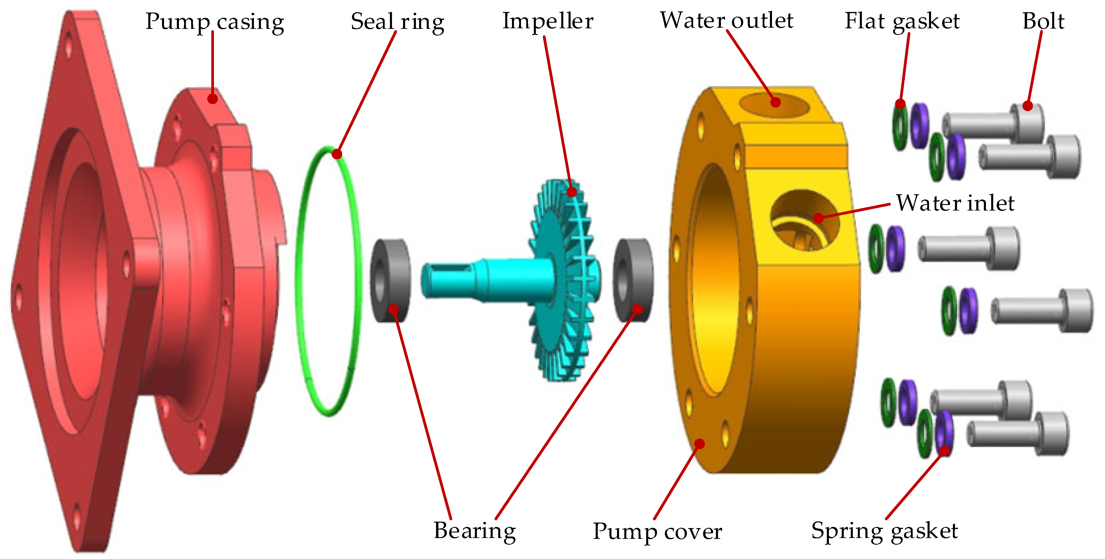
Figure 1 shows the structure of the closed double-bearing vortex pump, which is mainly composed of the pump casing, impeller, and pump cover. In the working process of the vortex pump, the main shaft drives the impeller to rotate clockwise under the support of the bearings at both ends. Due to the sealing ring connected to the pump casing and pump cover, the rotation of the impeller causes the air internal to the pump to be compressed and discharged through the water outlet, thereby creating a partial vacuum state internal to the pump. The external fluid medium is sucked into the flow channel of the pump through the water inlet, and the fluid is accelerated under the high-speed rotation of the impeller. The blades on the impeller generate thrust along the rotation direction of the fluid, so that the fluid obtains kinetic energy. At the same time, the vortex generated internally in the pump chamber promotes the acceleration and mixing of the fluid and promotes the accelerated fluid to flow to the outlet at higher velocity, so as to realize the high efficiency and high head operation of the vortex pump.

Figure 1.
Composition structure of the vortex pump.
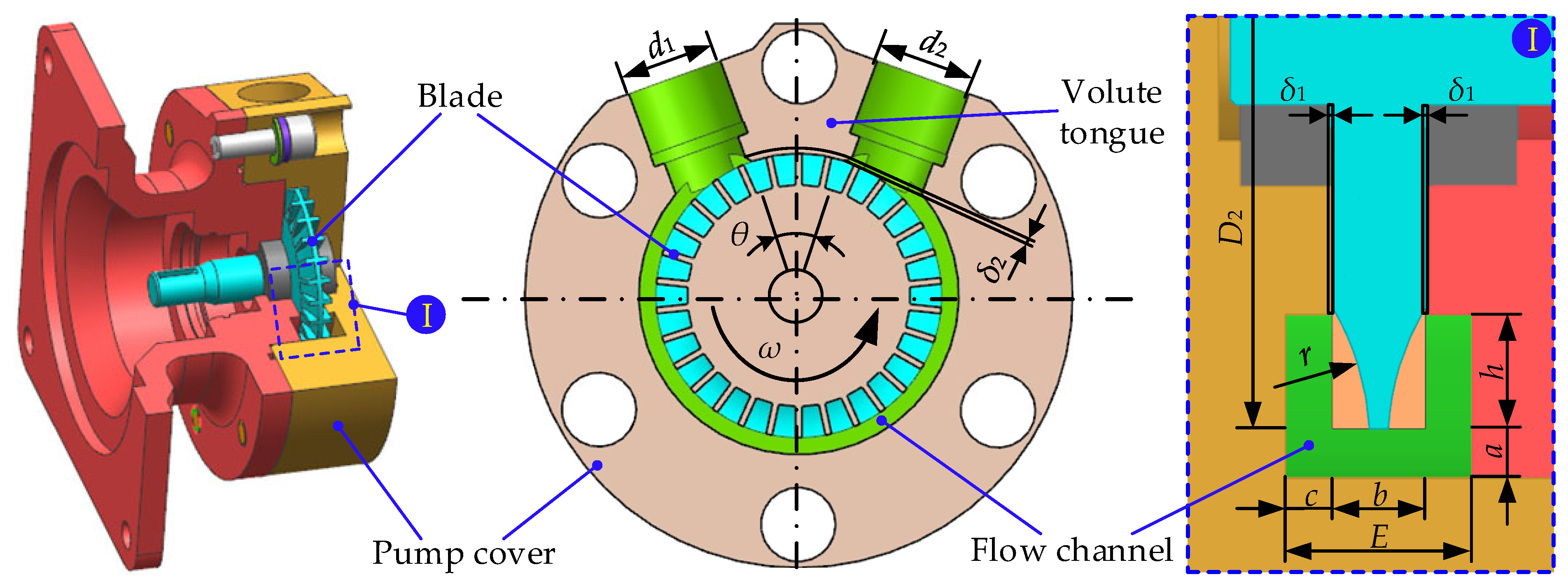
Figure 2 shows the internal structural details of the vortex pump and the corresponding main design parameters, as shown in Table 1. In which, the axial clearance between the pump shell, pump cover, and the end face of the impeller is δ1, and the radial clearance between the diaphragm tongue and the outer edge of the impeller is δ2.
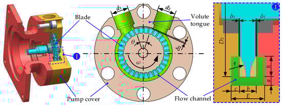
Figure 2.
Internal structure details of the vortex pump.

Table 1.
Main design parameters of the vortex pump.
2.2. Theoretical Model
2.2.1. Control Equation
The internal flow of the vortex pump is very complex, with phenomena such as an attached boundary layer, backflow vortex, and free shear turbulence formed during the impeller rotation. In order to ensure the accuracy and reliability of numerical simulation results, the RNG k-ε turbulence model combined with the Reynolds averaged Navier–Stokes (RANS) method is used for calculation. The RNG k-ε model is particularly suitable for dealing with both high Reynolds number and low Reynolds number flows and can effectively capture the detailed characteristics of the internal flow field of the vortex pump, which provides accurate data support for pump design and performance optimization.
The continuity equation plays a constraining role in ensuring mass conservation within the governing equations. When the fluid medium is an incompressible fluid, the equation is expressed as follows:
The Reynolds time-averaged equation is expressed as follows:
In which μt is the turbulent eddy viscosity and δij is the Kronecker delta symbol.
In the Reynolds time-averaging method, different turbulence models are derived using various assumptions about eddy viscosity and different modeling approaches.
The continuity equation and momentum equation for turbulent mean motion are as follows:
In which p is the pressure, μ is the dynamic viscosity, and i and j are the component indices of the vector.
In order to close the equation system, the transport equation can be established for the turbulent kinetic energy k. This k can then be used to construct the turbulent viscosity. The transport equation is as follows:
In which k is the kinetic energy (m2/s2) and Cμ, σk is the empirical constant.
The k equation is expressed as follows:
The ε equation is expressed as follows:
2.2.2. Main Performance
The performance of the vortex pump is usually characterized by its head, efficiency, and shaft power. In which, the expression for the head of the vortex pump is as follows:
where Po and Pi are the outlet static pressure and inlet static pressure of the pump, Vo and Vi are the outlet and inlet velocities of the pump, ρ is the density (its value is 998 kg/m3), g is the acceleration due to gravity (its value is 9.98 m/s2), and Δh is the height difference between the inlet and outlet (its value can be regarded as 0).
The expression for the efficiency of the vortex pump is as follows:
where Q is the mass flow rate, M is the torque, and ω is the rotational angular velocity, .
The expression for the power of the vortex pump shaft is as follows:
2.3. Simulation Model
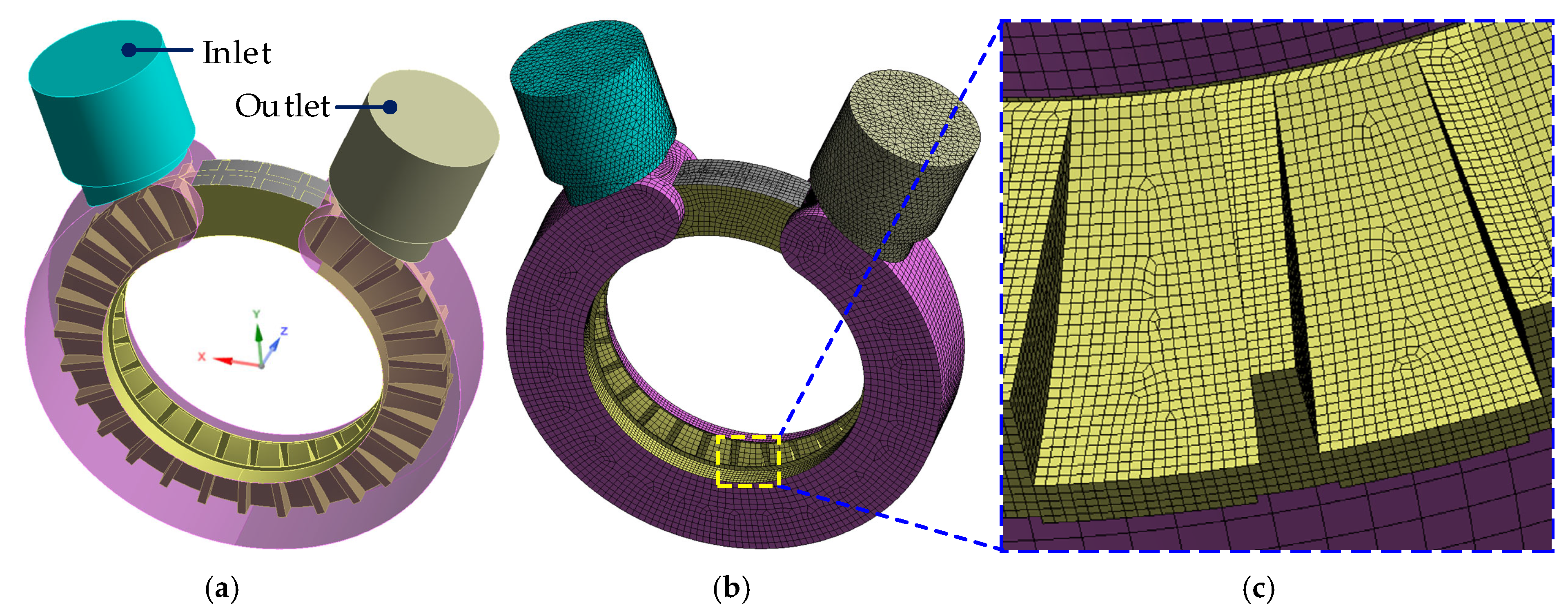
After the vortex pump model is established by UG software, the fluid is selected to flow at the inlet and outlet of the vortex pump and the inner surface of the flow channel for fluid domain volume extraction. The fluid domain of the vortex pump is the area between the pump casing and the pump cover other than the impeller. The numerical simulation of the vortex pump is carried out with the FLUENT 2022 R1 software, which is widely used in the field of fluid flow simulation and is based on the finite volume method with completely unstructured meshes. The internal fluid domain and mesh division are shown in Figure 3.
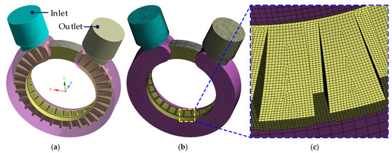
Figure 3.
Numerical calculation mesh: (a) fluid domain model, (b) mesh model, and (c) enlarged area.
In the process of analysis, either structured or unstructured meshes are commonly used, and unstructured meshes can make up for the lack of structured meshes that cannot solve any shapes and any connected areas. Due to the complex volume of irregular connections, such as the tongue area, the narrow area between the impeller and wall, and the variable sectional area at blade junctions in vortex pumps, the fluid domain is divided by the unstructured mesh method, and a tetrahedral computational mesh is generated. In general, the number of mesh divisions in the mesh model directly affects the calculation results. A larger number of mesh elements can improve the calculation accuracy but significantly increase the calculation cost, while a smaller number of mesh elements can save calculation time, but there are errors in the calculation accuracy. Therefore, it is necessary to verify the mesh independence of the mesh model by considering both computational efficiency and calculation result errors. The fluid domain model of the vortex pump is divided into five different mesh numbers to verify the mesh independence. When the number of meshes is increased from 7.62 × 10⁶ to 8.22 × 10⁶, the maximum error in the head and efficiency of the vortex pump is about 6.87%. When the number of meshes is further increased to 1.068 × 10⁷, the maximum error in the head and efficiency of the vortex pump is about 2.87%. Therefore, the overall number of meshes is finally selected to calculate the mesh model with 8.22 × 10⁶ mesh elements for the mesh model calculation to ensure high-precision simulation results within reasonable computational cost.
2.4. Boundary Condition
To determine the accuracy of numerical simulation, the inlet condition of the vortex pump is set as the mass flow boundary according to the law of conservation of mass. The inlet velocity V = Q/A is calculated by the given mass flow rate Q and the geometric dimensions A of the inlet channel section. Meanwhile, the turbulence intensity is calculated according to the Reynolds number Re at the inlet, and the inlet diameter is used as the hydraulic diameter. The initial pressure is set to standard atmospheric pressure with a value of 1.01325 × 10⁵ Pa, which is uniformly distributed over the inlet section. Considering that the pressure and velocity on the outlet boundary are both unknown, free outflow is adopted as the outlet boundary condition. This type of boundary condition is applicable to situations where the pressure or velocity on the outflow boundary is unknown and is calculated internally by FLUENT software without the need for special specification. Incompressible pure water is selected as the fluid medium, and a no-slip condition (relative velocity is zero) is adopted in the flow channel and the wall of the tongue area in the fluid domain. Impeller wall is defined as a moving wall condition with standard roughness models to more accurately simulate friction and resistance effects in actual flows. The fluid domain and impeller wall are set to the same rotation direction and rotation center to ensure consistency during the simulation process. To correct the underdeveloped area of turbulent flow, the second type of boundary condition based on pressure iteration calculation is adopted. The SIMPLE pressure–velocity coupling algorithm with fast convergence velocity is used to numerically simulate the vortex pump, in which the convergence standard is set at 1 × 10⁻⁵.
3. Calculation Results and Analysis
3.1. Influence of Different Rotational Speeds on Internal Fluid Velocity
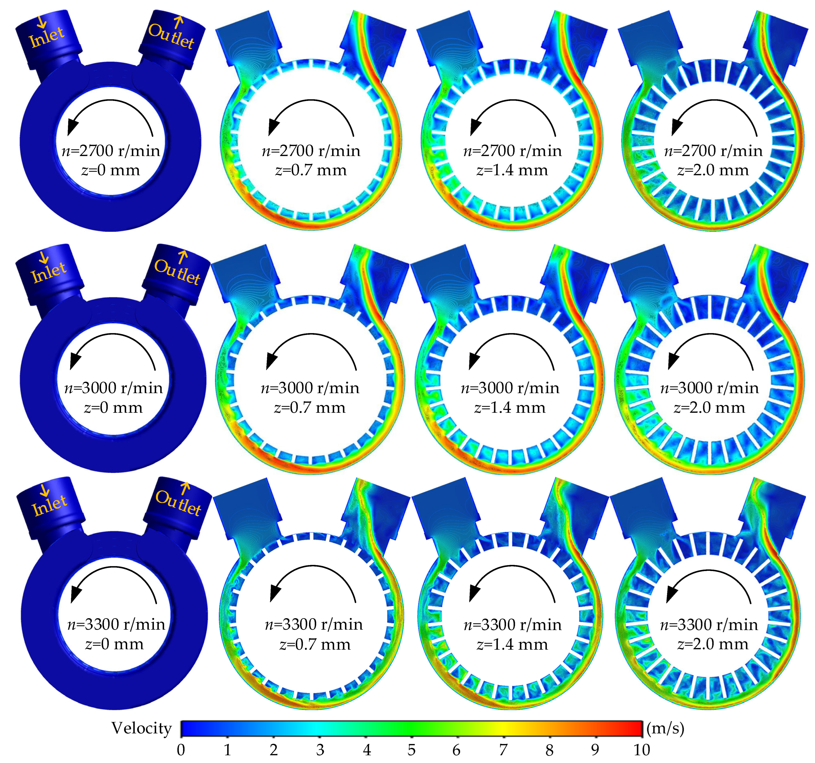
Figure 4 shows the influence of different rotational speeds on the internal fluid velocity of the vortex pump when the flow rate of the vortex pump is 0.6Qd. For the convenience of observation, four axial sections within the impeller basin are selected successively along the Z-axis direction from the outside to the internal at the same speed, namely, z = 0, 0.7, 1.4, and 2.0 mm. As shown in the figure, under the same speed, the fluid flows in the radial direction from the inlet of the vortex pump during the rotation of the impeller, through the internal flow channel to the outlet. In this process, the fluid velocity gradually increases along the flow channel. Except that the fluid flow velocity in the impeller blade groove basin is relatively chaotic, the velocity flow lines in other basins are basically similar. This is mainly due to the special structure of the vortex pump, which causes the higher velocity of the fluid to be mainly concentrated at the bottom of the flow channel and the outlet area. For the axial direction, at the z = 0 mm section, the velocity displayed at each point of the section is 0 m/s, which is due to the selection of no-slip conditions on the walls of the flow channel and tongue area. At the sections of z = 0.7, 1.4, and 2.0 mm, the internal fluid of the three sections flows in from the inlet and gradually increases in velocity, and the internal fluid flow velocity distribution is consistent. At the same time, under the rotation of the impeller, the fluid velocity gradually increases along the flow channel, pushing the fluid flow to the outlet, and the velocity reaches its maximum at the outlet. The fluid velocity gradually increases from both sides towards the center along the axial direction, and the closer it is to the outer edge of the impeller, the greater the fluid velocity. In addition, it can be observed that as the rotational speed increases from 2700 r/min to 3300 r/min, the fluid velocity in the flow channel continuously increases. This is due to the increasing rotational speed of the fluid impeller, so that more mechanical energy is converted into kinetic energy of the fluid, which leads to the gradual increase in the fluid velocity that continues to obtain energy in the flow channel. Compared to lower speeds, the maximum velocity of the fluid is closest to the outlet when the speed reaches 3300 r/min. The main reason for this phenomenon is that as the rotational speed of the impeller increases with the motor speed, the fluid velocity in the flow channel gradually increases with the increase in rotational speed. Moreover, as the flow velocity continues to increase, the maximum velocity of the fluid flowing towards the outlet gradually approaches the outermost edge of the flow channel.
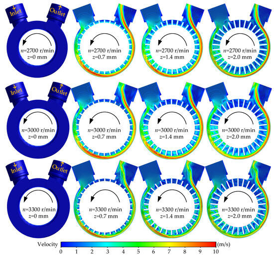
Figure 4.
Distribution of fluid velocity in an internal vortex pump at different rotational speeds.
3.2. Influence of Different Rotational Speeds on Internal Fluid Pressure
Figure 5 shows the influence of different rotational speeds on the internal fluid pressure of the vortex pump when the flow rate of the vortex pump is 0.6Qd. For ease of comparison, four axial sections at z = 0, 0.7, 1.4, and 2.0 mm within the impeller flow field are selected as reference interfaces at the same rotational speed. It can be clearly seen from the figure that under the same rotational speed condition, for the radial direction, as the rotational speed of the vortex pump increases, the fluid pressure from the inlet to the outlet along the flow direction shows a gradual increasing trend under the rotation of the impeller. In particular, the fluid pressure at the inlet of the vortex pump is negative, indicating the presence of a negative pressure area. According to the laws of energy conservation and Bernoulli, the kinetic energy of the fluid increases and the static energy decreases, resulting in a negative pressure area. From the pressure trace, it can be seen that as the fluid flows closer to the outer edge of the impeller, the pressure gradually increases. Starting from the center position of the tongue separation area of the vortex pump, it rotates counterclockwise. In the range of 0° to 180°, the fluid pressure of the vortex pump is negative, and the increasing trend of the internal fluid pressure of the vortex pump is relatively slow. After the fluid flows through 180°, the fluid pressure increases to a positive value. Under the continuous rotation of the impeller, the trend of fluid pressure increase becomes significantly faster, causing the fluid to flow out of the vortex pump at a higher pressure. For the axial direction, the pressure distribution pattern at each section is basically the same. As the fluid flows in from the inlet, the pressure gradually increases. Under the rotation of the impeller, the pressure gradually increases along the flow channel and reaches its maximum at the outlet. The energy accumulated by the impeller’s continuous work cycle is accumulated at the outlet, so that the fluid is pressurized and flows out at the outlet, resulting in a decrease in pressure in the tongue area. In addition, it can be observed that as the rotational speed increases from 2700 r/min to 3300 r/min, the pressure distribution of the internal fluid along the flow direction of the vortex pump under the action of impeller rotation is basically similar at different speeds. The increase in rotational speed of the vortex pump gradually increases the internal fluid pressure, especially in the area between the impeller and the outlet where the pressure reaches the maximum value.
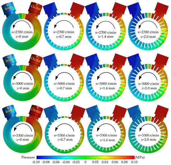
Figure 5.
Distribution of fluid pressure internal vortex pump at different rotational speeds.
3.3. Characteristics of Fluid Velocity and Pressure Changes Under Different Circumferential Sections
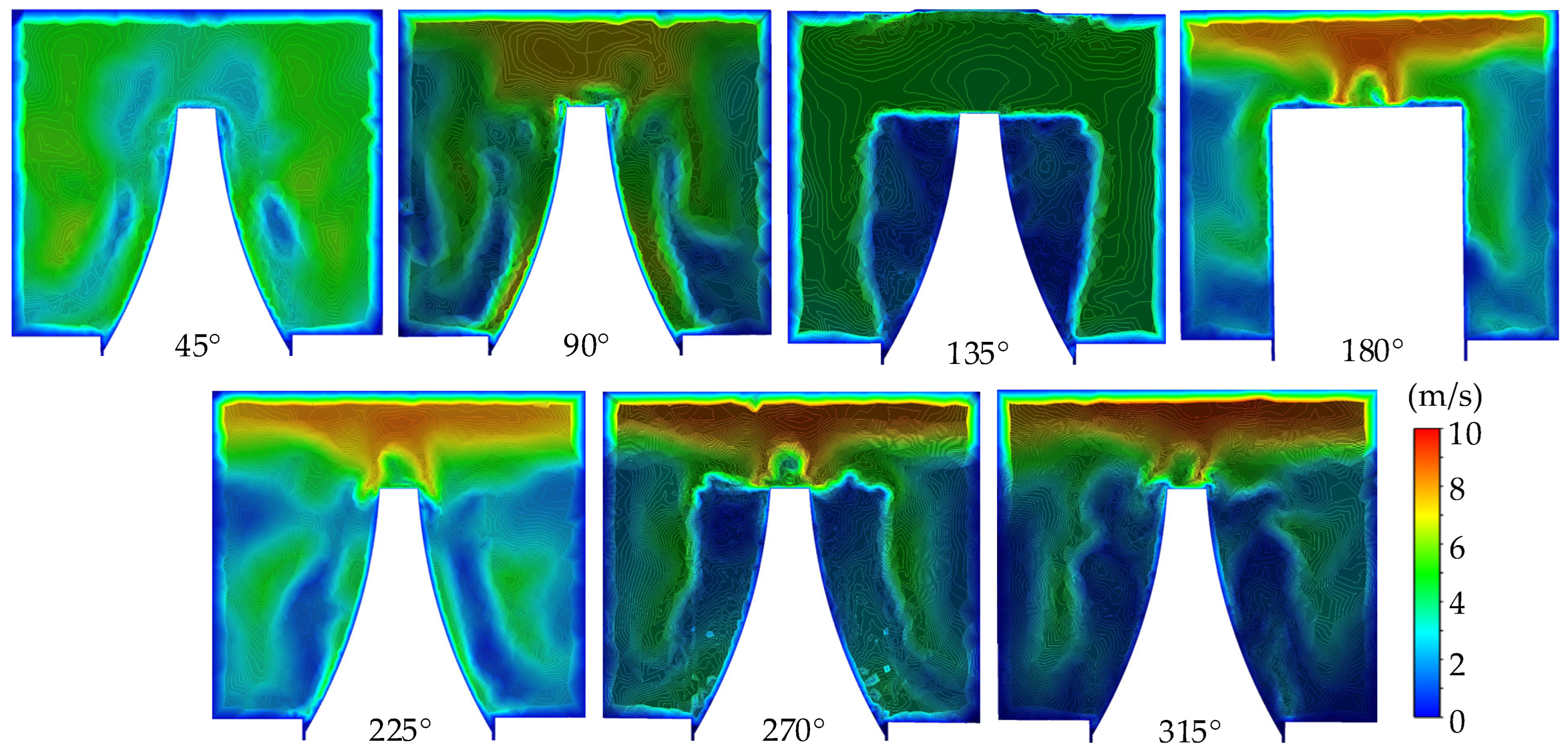
Figure 6 shows the fluid velocity distribution in the vortex pump channel at different circumferential sections when the flow rate of the vortex pump is 0.6Qd and the rotational speed is 2700 r/min. In which, the section starts from the positive direction of the Y-axis and rotates counterclockwise around the Z-axis, taking sections at positions 45°, 90°, 135°, 180°, 225°, 270°, and 315° in sequence. It can be seen from the figure that under the rotation of the impeller, there is a symmetrical fluid velocity distribution wake in the area outside the radius of the impeller at each section, and the fluid velocity gradually increases along the flow velocity. The fluid velocity is higher near the impeller and along the outer edge of the flow channel. At the section from 45° to 315°, the outermost velocity of the channel is 0 m/s, which is also due to the fact that the wall condition is set to no slip during the numerical calculation. At the 180° section, the fluid velocity and pressure are both relatively high due to the rotation effect of the impeller and the gravity of the fluid itself. At the 315° section, the fluid velocity is maximum at the outlet due to the fluid accumulating energy and flowing towards the outlet during the continuous rotation of the impeller.
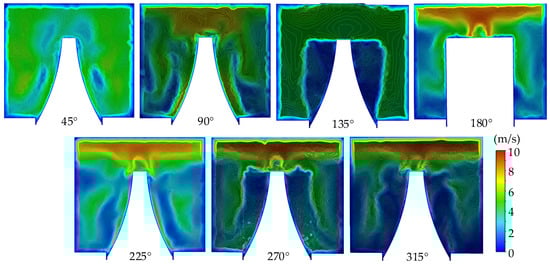
Figure 6.
Distribution of circumferential sectional velocity of the vortex pump.
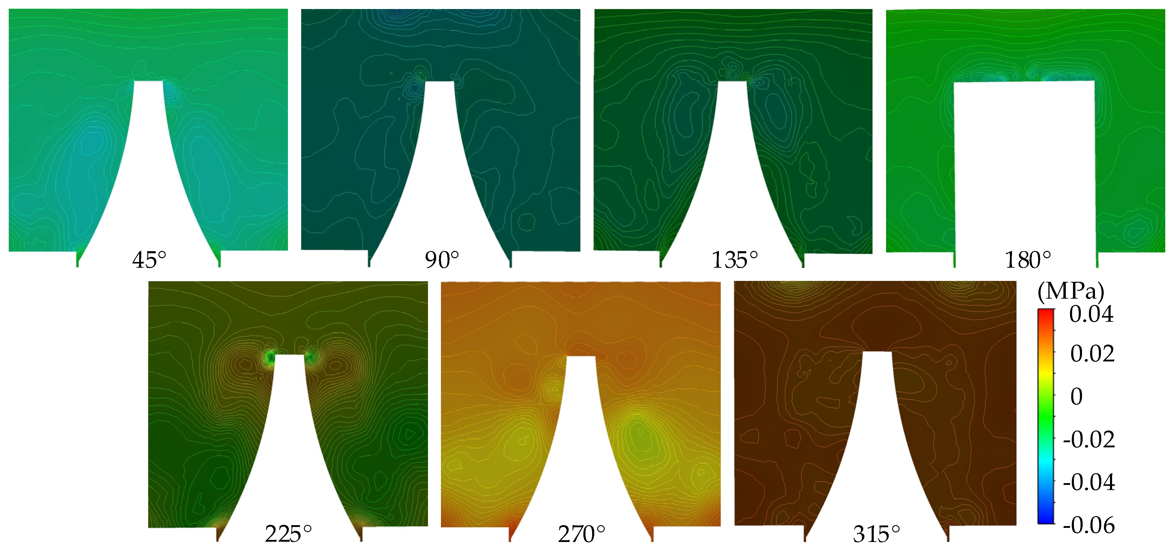
Figure 7 shows the pressure distribution in the circumferential section of the vortex pump, and the section position corresponds to Figure 6. As shown in the figure, the wake flow is formed on the circumferential section due to the rotational force of the impeller on the fluid, resulting in the pressure distribution of the fluid internal to the vortex pump being basically similar in different sections, and the pressure distribution of the outer flow channel showing symmetry. The pressure on the fluid along the flow direction gradually increases under the rotation of the impeller, with the minimum pressure at the 45° section and the maximum pressure at the 315° section. This is because the fluid enters the flow channel from the inlet and flows along the channel to the outlet under the rotation of the impeller. The fluid in the blade is under the influence of the periodic rotation of the continuous accumulation of energy gained at the outlet to reach the maximum pressure so that the vortex pump can obtain the high head.
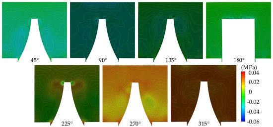
Figure 7.
Distribution of pressure in the circumferential section of the vortex pump.
3.4. Characteristics of Fluid Velocity Vector Variation Under Different Sections
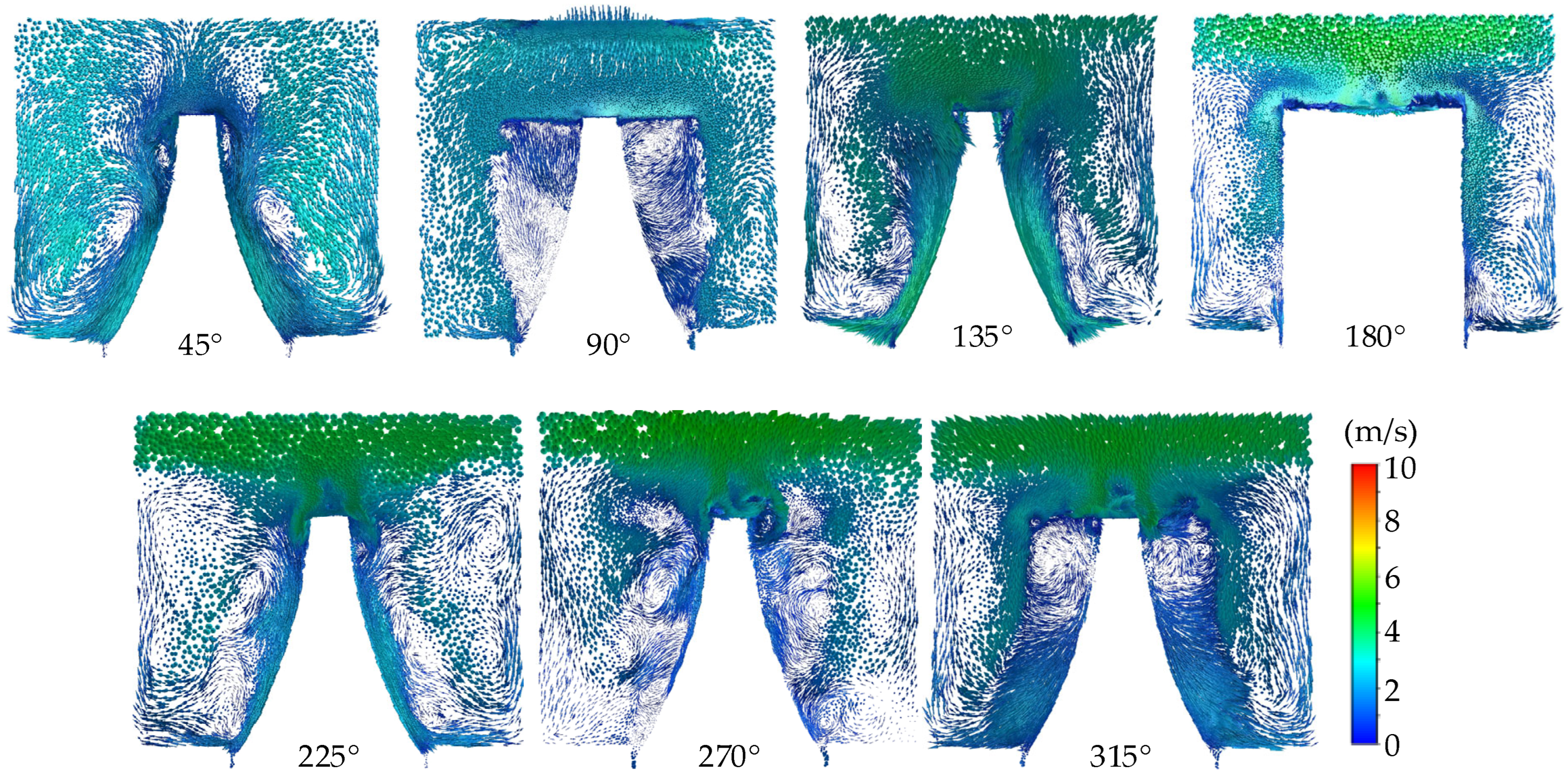
Figure 8 shows the fluid velocity vector distribution in the vortex pump flow channel at different circumferential sections when the conditions are as follows: the flow rate of 0.6Qd and the rotational speed of 2700 m/s. Corresponding to Figure 6 and Figure 7, it can be seen from the figure that the distributed blades on the impeller of the vortex pump lead to a complex flow field structure internally. The distribution law of the velocity field and vortex structure in each section is basically similar. At the sections of 45°, 270°, and 315°, the impeller and the outer edge of the flow channel show obvious vortex structure. This is mainly because under the influence of the high-speed rotation of the impeller, a large axial component velocity is formed at the rotating wall under different circumferential angle sections, and a symmetrical vortex is formed at the clearance between the blade and the flow channel. According to the direction indicated by the velocity arrow, it can be seen that the periodic rotation of the impeller not only transfers kinetic energy but also carries out energy exchange so that the fluid forms a spiral vortex structure after entering the flow channel and advances periodically along with the rotation direction of the impeller. At the root of the blade, the upward movement of the fluid produces a longitudinal radial vortex, which is transformed into a transverse circumferential vortex by the rotating action of the impeller. In the process of impeller rotation, the fluid is impacted by the blade, causing the liquid to fall off and form a vortex, which is a radial vortex parallel to the vector direction at the inlet edge of the blade. Each particle of the fluid flow in the flow channel follows the principle of equal moment of momentum and equal angular velocity. The fluid is continuously squeezed from the inlet to the outlet during the rotating process of the impeller, resulting in different circular velocities and uneven forces between the fluid in the outflow channel of the impeller and the squeezed fluid in the impeller, so the circular motion of the fluid in the flow channel is formed, which is the longitudinal vortex. The fluid in the flow channel is periodically removed from the blade along the flow direction under the action of the impeller rotation, and the fluid is circulated to the outlet, and the energy transmitted by the blade is continuously accumulated so that the vortex pump can obtain a higher head.
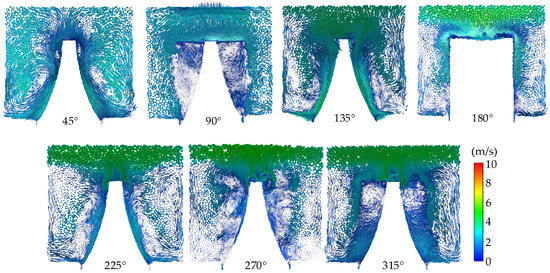
Figure 8.
Distribution of velocity vector in the circumferential section of the vortex pump.
4. Experimental Verification
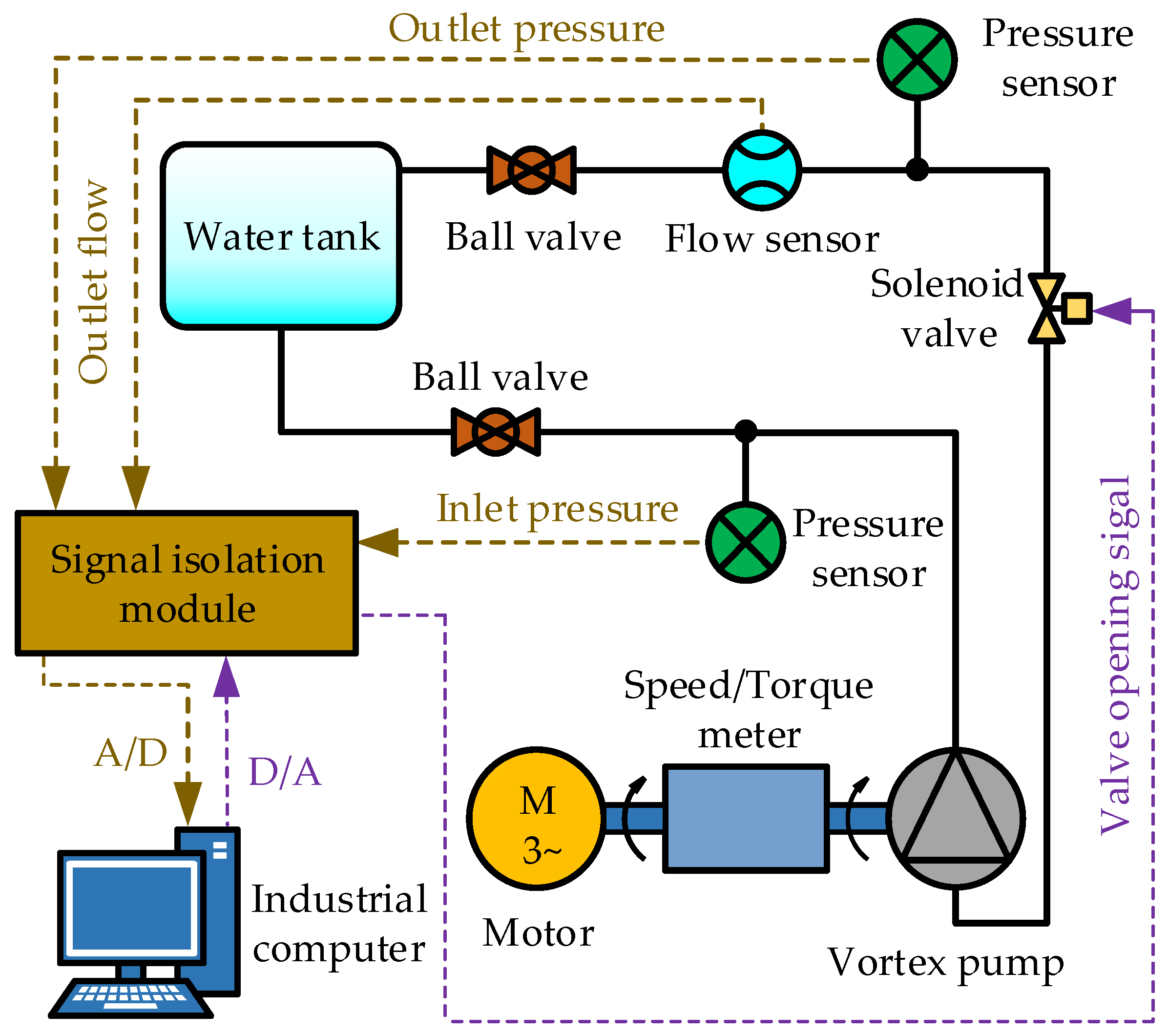
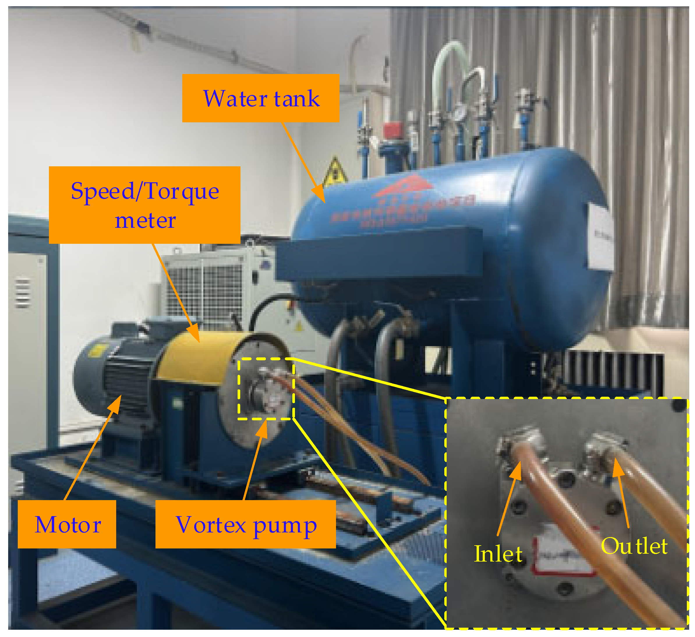
In order to ensure the reliability and accuracy of the numerical simulation study, the external characteristic experiment is carried out on the comprehensive performance experimental bench of the vortex pump. The experimental bench consists of the following two parts: the hardware system and the software system, with the system principle and physical composition shown in Figure 9 and Figure 10, respectively.
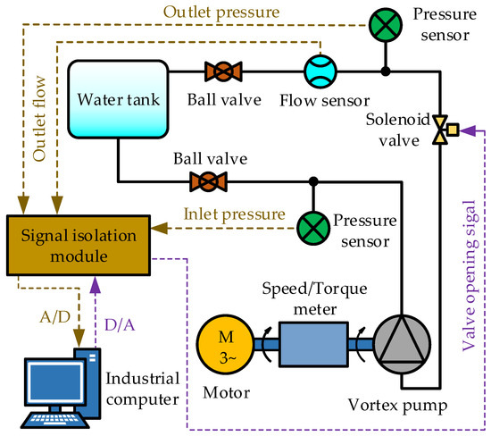
Figure 9.
System principle of the experiment bench.
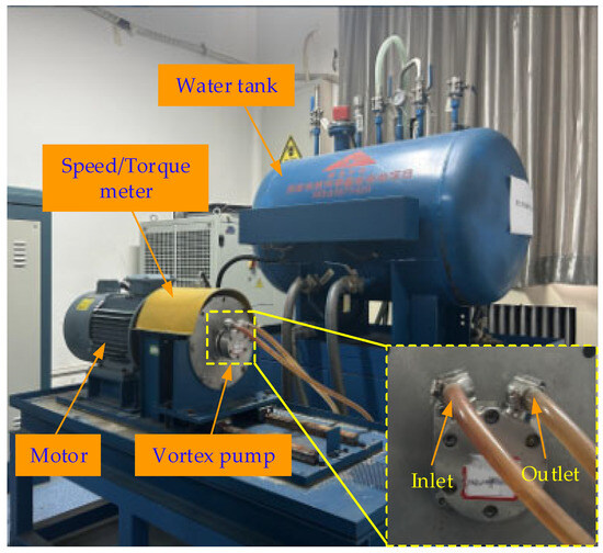
Figure 10.
Physical composition of the bench.
In the hardware system, the output frequency of the frequency converter can be adjusted to change the output speed of the motor (ABB, YVF5.5KW, Shanghai, China), which in turn drives the vortex pump to flow the liquid from the inlet to the outlet back to the water tank at different speeds. In which, the ball valve (BEST, H14W-25R DN25, Wuxi, China) in the inlet and outlet pipelines of the vortex pump plays a throttling role, and the solenoid valve (BEST, Z291/292-25RII24-16, Wuxi, China) on the outlet pipeline exerts pressure on the water. In the software system, the signal acquisition device converts the analog signals of the pressure sensor (WIKA, A-10, Suzhou, China), flow sensor (BEST, C8004-25RIII24-CG05, Wuxi, China), and speed torque sensor (ETH, DRBK-I-50NM, Shanghai, China) into digital signals and sends them to the industrial computer (ADVANTECH, PCI610L, Shaanxi, China) to achieve overall control of the hydraulic circuit. The experiment bench measurement and control program developed by LabVIEW 2019 software on the industrial computer can adjust the output digital signal through the signal control device, so as to precisely control the opening of the solenoid valve and then adjust the flow in the water hydraulic circuit. The pressure sensor collects pressure data at the inlet and outlet of the vortex pump, the flowmeter collects real-time flow data of the measured water hydraulic circuit, and the signal acquisition device collects and converts the above analog signals into digital signals and transmits them to the industrial computer to obtain the experimental data.
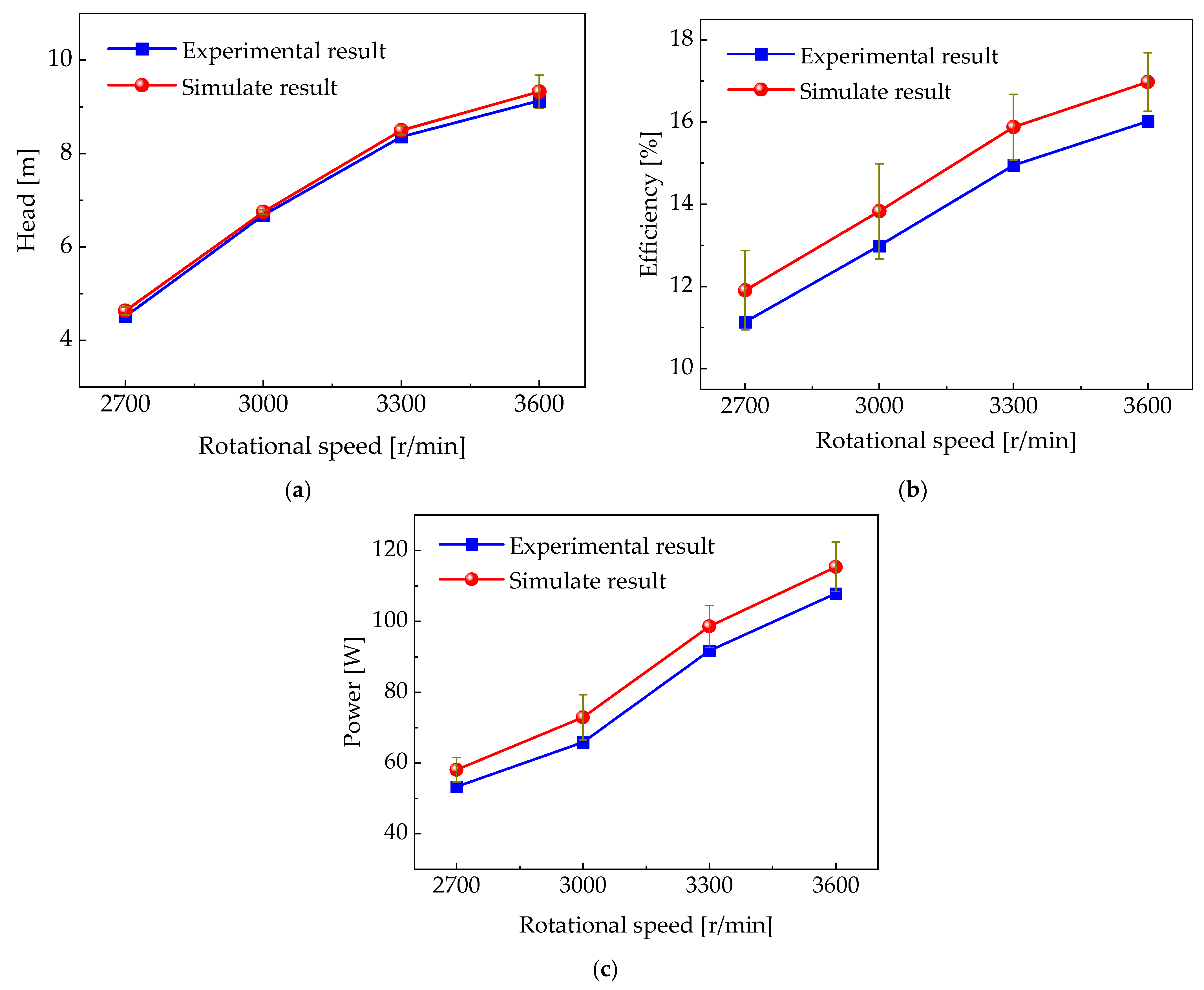
In order to verify the accuracy of the test results, 10 repeated tests of the vortex pump were carried out on the comprehensive performance test bench. During the test, the error of flow rate is ±2%, the error of head is ±0.7%, the error of shaft power is ±1.5%, and the error of speed is ±0.2%. At the flow rate of 0.6Qd, external characteristic tests were conducted on the vortex pump under four different operating conditions of 2700, 3000, 3300, and 3600 r/min. The results are shown in Figure 11. It can be seen that under the fixed impeller structure parameters and working conditions of the vortex pump, the numerical simulation results are generally higher than the experimental results, and there are certain deviations between the two results. If the error between numerical simulation and experimental results exceeds 10%, the potential sources of error mainly include grid dependence and experimental setup limitations. Unevenness in mesh processing, different element types and sizes, as well as complex geometry and heterogeneous material properties, will significantly affect the accuracy of the calculation. In the experiment setup, the boundary and initial conditions do not match the simulation assumptions, the measurement equipment accuracy is insufficient, and the influence of the test environment factors may lead to errors. These errors reduce the credibility of the theoretical model, limit its scope of application, weaken the reliability of the research conclusions, increase the risk of drawing wrong conclusions, and may lead to the waste of computing resources.
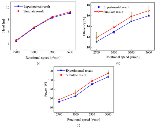
Figure 11.
Comparison of simulation and experiment results: (a) head of vortex pump, (b) efficiency of vortex pump, and (c) shaft power of vortex pump.
In terms of head, the experimental results and numerical simulation results show that the head increases with the increase in speed at different speeds, with a maximum error of 2.7%, a minimum error of 1.04%, and an average error of 1.89%. In terms of efficiency, the efficiency increases with the increase in rotational speed. The maximum error between experimental results and numerical simulation results is 6.46%, the minimum error is 5.65%, and the average error is 6.01%. In terms of shaft power, the shaft power increases with the increase in rotational speed. The maximum error between experimental results and numerical simulation results is 9.67%, the minimum error is 6.45%, and the average error is 7.85%. These experimental results showed good consistency with the simulation results, and the error range between the simulation results and the experimental results is within 10%, which verifies the reliability of the numerical simulation results and provides strong support for further performance optimization of the vortex pump.
5. Structural Optimization of the Vortex Pump
The orthogonal experimental design method is a kind of experimental design technique that combines statistics and orthogonality principles, which can effectively improve the efficiency of multi-factor and multi-level experiments by reducing the number and period of experiments. In this method, the factors and levels of the experiment are allocated reasonably through the balanced dispersion and orthogonal principles, and the orthogonal table is used to construct the experiment scheme to ensure the statistical representativeness of the results. In practical applications, by simulating experimental results and calculating the mean and range, the optimal structural parameters can be evaluated and selected. In the performance optimization of double-bearing the vortex pump, the reasonable selection of geometrical parameters of the flow components in the pump (such as impeller structure size and flow channel size) affects the pump performance significantly. The effects of these parameters on pump performance can be systematically analyzed by the orthogonal experimental method, and the optimal structural configuration can be selected to improve pump efficiency and reduce energy consumption.
5.1. Optimization Scheme
The impeller is the core component of the vortex pump, and the geometric design of its blade plays a decisive role in the hydraulic performance and the flow characteristics of the vortex pump. In the orthogonal experimental design, four structural parameters of impeller diameter D2, blade groove radius r, blade number Z, and impeller width b are selected as experimental factors. The specific reasons for selection and parameters are determined as follows:
- Impeller diameter D2: The recommended design range of impeller diameter D2 is usually 40~50 mm. For closed vortex pumps, it is necessary to consider that the value range of the clearance δ2 between the impeller and the baffle tongue is usually 0.1~0.3 mm. Based on the basic parameter D2, which is 45.9 mm of the impeller diameter of the original model in Table 1, the corresponding value of δ2 is 0.1. Compared with the original model, the values of the slightly smaller 45.7 and 45.8, the final D2 is selected as 45.7, 45.8, and 45.9 as the three levels for D2.
- Blade groove radius r: The blade groove is the hub structure connecting the blade, and its radius plays a decisive role in the overall performance of the pump. If the radius of the blade groove is small, the tip of the groove can be sharp, which inhibits the formation of vortices and reduces the effective transfer of energy. In contrast, if the radius of the blade groove is large, the flow of fluid between the vanes is restricted, which prevents the smooth flow of fluid and leads to the decline in the overall performance of the pump. Therefore, based on the basic parameter r of the blade groove radius of 15 of the vortex pump for the original model in Table 1, the final r is 14.9, 15, and 15.1 as the three levels.
- Blade number Z: Through preliminary screening through single-factor simulation calculation, the overall performance of the vortex pump is poor when the number of blades is less than 27. When the number of blades is 27~33, the pump head can be increased. When the number of blades is greater than 33, the increase in head and efficiency growth slows down or even decreases in order to reduce the load per unit area of the blade and enhance the constraint of the fluid between the blades. Therefore, based on the basic parameter Z of the blade number, which is 30 of the vortex pump blades for the original model in Table 1, the final Z is selected as 28, 30, and 32 as three levels.
- Impeller width b: The axial clearance δ1 formed between the impeller and the shell is the key parameter that affects the flow rate and high head, and the value of δ1 is usually 0.04~0.25 mm. In order to reduce the volume loss of the vortex pump and meet the performance of the pump, the δ1 value corresponding to 5.15 of the impeller width b of the original model in Table 1 is 0.22. Considering that it is convenient to compare the performance differences between the two larger impeller widths and the original model impeller width, we selected the value 5.37, which lies midway between 5.15 and 5.51. Therefore, the value 5.37, which is larger than both 5.15 and 5.51, was chosen. Finally, 5.15, 5.37, and 5.51 are selected as the three levels for b.
In order to explore the optimal matching relationship between the performance of the vortex pump and the four structural parameters of the impeller, the orthogonal experiment is developed based on the four factors, three levels, and their corresponding values determined above, and the experimental factors and levels are shown in Table 2, in which the four factors D2, r, Z, and b are represented by A, B, C, and D, respectively. By referring to the factors and levels in Table 2, the orthogonal design table L9(43) can be applied to plan the orthogonal experiment so that the design scheme of 9 sets of design schemes for optimizing the impeller structure can be obtained, as shown in Table 3.
Table 2.
Factors and levels of orthogonal experiment.
Table 3.
Design scheme of orthogonal experiment.
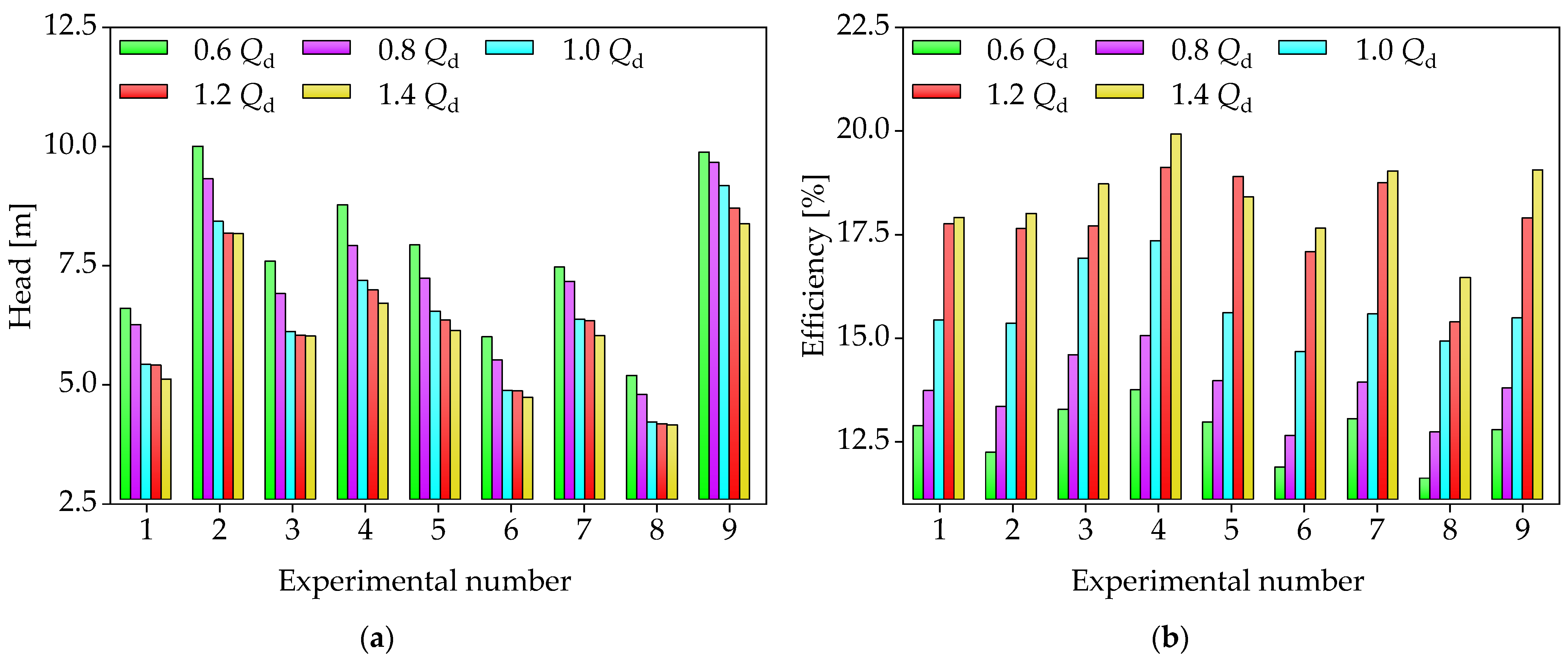
Under the working conditions of 0.6Qd, 0.8Qd, 1.0Qd, 1.2Qd, and 1.4Qd, numerical calculations were performed for each scheme in Table 3, and the results are shown in Figure 12. As shown in the figure, the output head of the vortex pump gradually decreases with increasing flow rate. This is because during the process of motor output power, the work of the impeller overcoming its own weight and fluid resistance increases, resulting in a gradual decrease in pump head with increasing flow rate. The efficiency of the vortex pump shows an overall upward trend with the increase in flow rate, with a faster growth trend in the 0.6Qd~1.0Qd condition and a slower growth trend in the 1.2Qd and 1.4Qd condition.
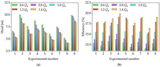
Figure 12.
Numerical simulation results under different operating conditions: (a) head of vortex pump and (b) efficiency of vortex pump.
5.2. Optimal Results
Perform range analysis on the numerical calculation results under the operating conditions of 0.6Qd~1.4Qd, as shown in Table 4. (i = 1, 2, 3) value is the mean value, which refers to the average sum of the corresponding experimental results for each factor. R is the range, which is the maximum minus the minimum value of for each factor. If the R value corresponding to a certain factor is larger, it indicates that the influence of that factor on the performance of the vortex pump is more significant, and it is the primary factor of the orthogonal test, and the other is the secondary factor.
Table 4.
Range analysis.
According to the range analysis in Table 4, it can be concluded as follows:
- Under the working condition of 0.6Qd~1.0Qd, the influence degree of each factor on the head H is C, D, A, and B from large to small.
- Under the condition of 0.6Qd~0.8Qd, the values of B and C are close, and the degree of influence of each factor on the efficiency η is C, B, D, and A in order from large to small. Under the working condition of 1.2Qd~1.4Qd, the influence degree of each factor on the efficiency η is C, B, A, and D in order from large to small. Under 1.0Qd condition, the values of B, C, and D are close, and the degree of influence of each factor on the efficiency η is D, C, B, and A in order from large to small. Since the design of the vortex pump model is more focused on the efficiency improvement of the rated working condition of 1.0Qd. Overall, in the working condition of 0.6Qd~1.4Qd, the influence degree of each factor on η is C, B, D, and A in order from large to small.
- In the working condition of 0.6Qd~1.4Qd, the value of C is far greater than the value of the other three factors, and C can be determined as the primary factor affecting the performance of the vortex pump.
Through the analysis of the values in Table 4, the optimal horizontal combination can be initially selected, as shown in Table 5.
Table 5.
Optimal level combination.
For the efficiency, in view of the current efficiency characteristics of the vortex pump, the efficiency under the condition of 0.6Qd~1.0Qd needs to be improved.
For the head, according to the design requirements, considering the difference between the original model simulation of the vortex pump and the test results, the higher the optimized head is, the better for the 0.6Qd~1.4Qd working condition.
The purpose of using the orthogonal design method is to further improve the head performance of the vortex pump while taking into account its efficiency. Combined with Table 4 and Table 5, the parameter optimization analysis is as follows:
Factor A (D2): The impact of A on the head and efficiency of the vortex pump is relatively small. For the head, the A1 value is the largest under the condition of 0.6Qd~1.0Qd. For the efficiency, the A1 value is close to the A2 value. Considering the shape of the flow channel and radial clearance comprehensively, the optimal level of factor A is finally determined to be A1.
Factor B (r): B is a secondary factor affecting efficiency, yet it minimizes the effect on head. For the head, the values of B1, B2, and B3 are similar. For the efficiency, the value of B1 is greater than B2 and B3 under the condition of 0.6Qd~1.0Qd. In order to take into account pump head and improve efficiency, the optimal level of factor B is finally determined to be B1.
Factor C (Z): C is the primary factor affecting pump head and efficiency. For the efficiency, the C2 value is larger under the conditions of 0.6Qd, 0.8Qd, and 1.2Qd. Under 1.0Qd and 1.4Qd conditions, the C3 value is larger. For the head, the C3 value is the largest under the condition of 0.6Qd~1.4Qd. Considering the casting process of the blade comprehensively, the optimal level of factor C is finally determined to be C3.
Factor D (b): D is a secondary factor affecting the lift. For the head, the value of D1 is the largest under the condition of 0.6Qd~1.0Qd. For the efficiency, D1, D2, and D3 values are close. In order to ensure pump head and reduce pump volumetric efficiency loss, the optimal level of factor D is finally determined to be D1.
In order to ensure the performance and reliability of the vortex pump, it is necessary to analyze the primary and secondary order of various factors affecting the performance changes of the vortex pump, as shown in Figure 13. As shown in the figure, when the flow rate of the vortex pump varies between 0.6Qd and 1.4Qd, the order of the influence of the four factors on the head of the vortex pump is C, D, A, and B. The factor with the greatest impact on the efficiency of the vortex pump among the four factors is C, followed by B. In addition, to meet the purpose of the vortex pump to achieve high head, the optimal combination of four factors is ultimately selected as A1B1C3D1, which is D2 = 45.7 mm, r = 14.9 mm, Z = 32, and b = 5.15 mm.
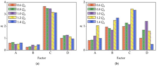
Figure 13.
Primary and secondary analysis of orthogonal experiment factors: (a) head of vortex pump and (b) efficiency of vortex pump.
5.3. Comparison of External Characteristics
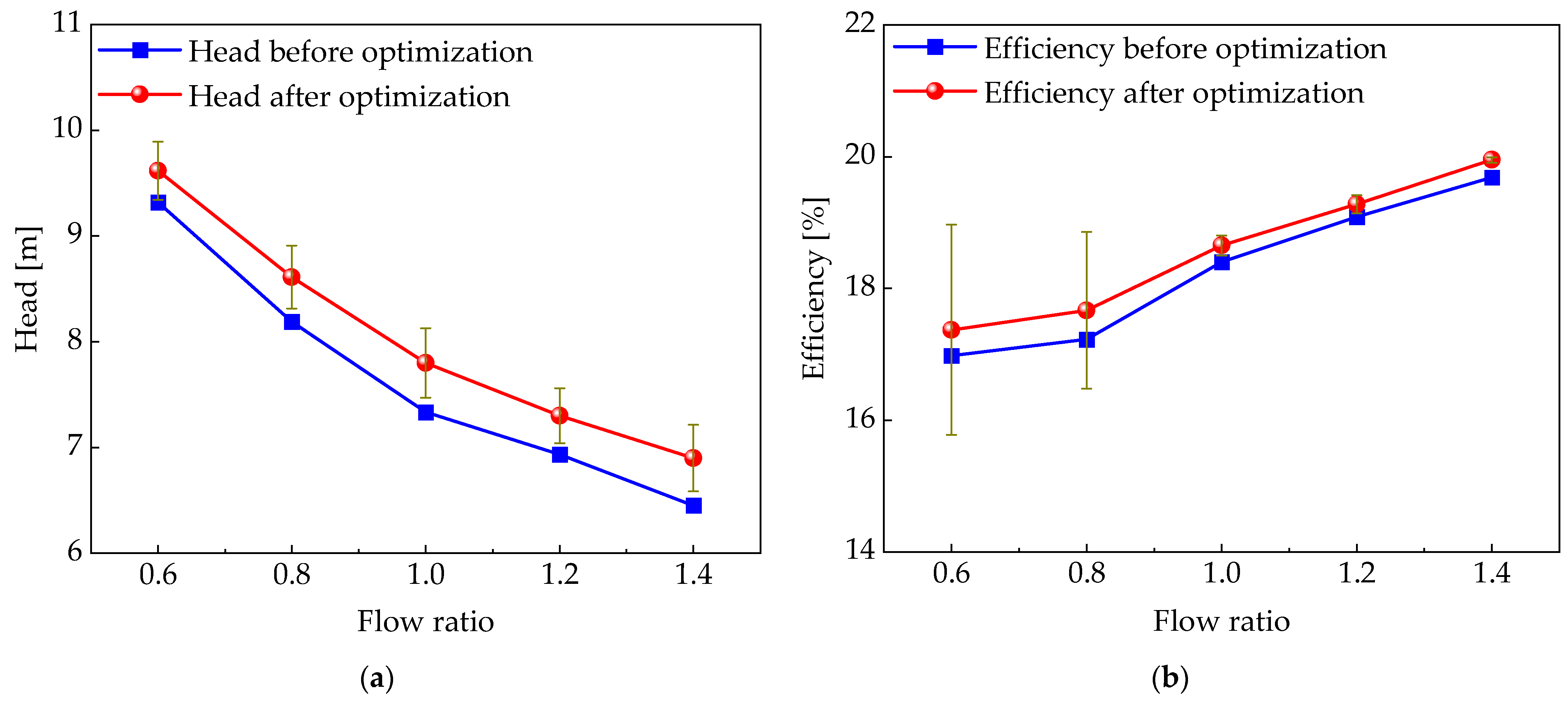
To further illustrate the performance changes of the vortex pump before and after optimization, the performance difference between the orthogonal design-optimized vortex pump model and the original model is compared by numerical simulation under the working speed of 3600 r/min, as shown in Figure 14. The simulation results show that the efficiency of the optimized vortex pump is significantly higher than that of the original model before optimization under low flow conditions of 0.6Qd~0.8Qd. Under the 1.0Qd~1.4Qd conditions, the efficiency of the vortex pump before and after optimization is close.
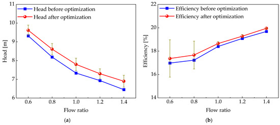
Figure 14.
Comparison results before and after optimization of vortex pump: (a) head of vortex pump and (b) efficiency of vortex pump.
In addition, although the variation trend of the vortex pump head after optimization is similar to that of the original model, which decreases with the increase in flow rate, the vortex pump head of the optimized model is better than that of the original model under all test conditions. Specifically, the optimized model increased the head from 7.64 m to 9.09 m and the efficiency from 11.79% to 13.16% under the design conditions. This indicates that the vortex pump head is increased by 18.9% and the efficiency by 11.6% through the orthogonal optimization method, thus verifying the effectiveness of the optimization measures in improving pump performance. Performance changes of the vortex pump before and after optimization as shown in Table 6.
Table 6.
Performance changes of the vortex pump before and after optimization.
6. Conclusions
In this paper, the characteristics of the internal flow field of the vortex pump are deeply studied by the numerical simulation method and compared with the experimental data to verify the accuracy of the simulation results. On this basis, the impeller structure of the vortex pump is optimized using the orthogonal design method, and the overall performance of the optimized vortex pump has been significantly improved. In summary, the following conclusions can be formulated:
- The internal fluid velocity of the vortex pump is closely related to the speed of the pump. As the rotational speed increases, the fluid velocity gradually increases, especially in the outer edge area of the impeller. At the same time, the fluid pressure also increases, which promotes the formation of higher pressure at the outlet of the pump, thereby achieving high head.
- The flow field structure internal to the vortex pump is extremely complex, and the fluid generates longitudinal vortices in the blade root area, which are subsequently transformed into transverse vortices. The fluid in the flow channel forms circular longitudinal vortices, and the continuous formation and shedding of these vortices provide continuous energy output for the vortex pump, which improves the performance of the pump.
- The system performance of the vortex pump is optimized by applying the orthogonal design method. The range analysis method further determines the primary factors affecting pump performance, which are the number of blades, impeller width, impeller diameter, and blade groove radius. Through the optimization, the optimal combination of impeller structural parameters is determined as impeller diameter D2 of 45.7 mm, blade groove radius r of 14.9 mm, blade number Z of 32, and impeller width b of 5.15 mm. The optimization of these parameters significantly improved the overall performance of the vortex pump.
Optimizing the performance of vortex pumps can significantly improve energy efficiency and reliability, extend service life, and reduce operating costs. In industrial applications, it can better meet the needs for small flow and high head in the chemical, aviation, marine, fire protection, agricultural irrigation, and building water supply industries, providing more efficient and reliable fluid transport solutions to enhance overall system performance. It should be emphasized that in this paper, the interactions between the influencing factors are ignored during the orthogonal design process. Therefore, this needs to be studied in depth in future studies.
Author Contributions
Conceptualization, J.Y. and D.C.; methodology, J.Y., X.L. and D.C.; software, J.Y.; validation, J.Y. and X.L.; formal analysis, J.Y. and X.L.; investigation, J.Y., X.L., D.C. and J.J.; resources, J.Y.; data curation, J.Y.; writing—original draft preparation, J.Y. and D.C.; writing—review and editing, J.Y. and D.C.; visualization, J.Y. and D.C.; supervision, X.L. and M.Z.; project administration, X.L., W.G. and L.H.; funding acquisition, X.L., W.G. and L.H. All authors have read and agreed to the published version of the manuscript.
Funding
This research was funded by the Natural Science Basic Research Project of Shaanxi Province, China (No. S2024-JC-YB-0014) and the Hydraulic Technology Key Laboratory of Shaanxi Province Open Fund Research Project (No. YYJS2022KF09 and No. YYJS2022KF11).
Institutional Review Board Statement
Not applicable.
Informed Consent Statement
Not applicable.
Data Availability Statement
The original contributions presented in the study are included in the article, further inquiries can be directed to the corresponding author.
Conflicts of Interest
The authors declare no conflicts of interest.
References
- Quan, H.; Fu, B.H.; Li, R.N.; Zhang, T.; Han, W.; Li, J. Research stage and development tendency of vortex pump. Fluid Mach. 2016, 44, 36–40. [Google Scholar]
- Zhang, F.; Fleder, A.; Böhle, M.; Yuan, S.Q. Effect of suction side blade profile on the performance of a side channel pump. Proc. Inst. Mech. Eng. Part A J. Power Energy 2016, 230, 586–597. [Google Scholar] [CrossRef]
- Mihalic, T.; Guzovic, Z.; Predin, A. Performances and flow analysis in the centrifugal vortex pump. J. Fluids Eng. 2013, 135, 011107. [Google Scholar] [CrossRef]
- Liu, R.J.; Zheng, F.J.; Fu, P.D.; Wang, P. Orthogonal test and experimental study on fire floating pump. IOP Conf. Ser. Mater. Sci. Eng. 2013, 52, 032010. [Google Scholar] [CrossRef]
- Mosshammer, M.; Benigni, H.; Jaberg, H.; Konrad, J. Maximum Efficiency Despite Lowest Specific Speed-Simulation and Optimisation of a Side Channel Pump. Int. J. Turbomach. Propuls. Power 2019, 4, 6. [Google Scholar] [CrossRef]
- Zhang, B.W.; Cheng, L.; Zhu, M.H.; Jiao, W.X.; Zhang, D. Numerical simulation and analysis of the flow characteristics of the roof-attached vortex (RAV) in a closed pump sump. Machines 2022, 10, 209. [Google Scholar] [CrossRef]
- Wu, X.; Shao, C.; Tan, M.; Liu, H.; Hua, R.; Li, H. Unsteady flow and excitation characteristics in a vortex pump. Flow Meas. Instrum. 2024, 100, 102716. [Google Scholar] [CrossRef]
- Cheng, Y.; Li, W.; Ma, S.; Ji, L.; Xiao, C.; Li, Y. The Influence of Different Working Fluid Temperatures on the Hydraulic Performance of Magnetic Vortex Pumps. Water 2024, 16, 1601. [Google Scholar] [CrossRef]
- Zhao, K.; Tan, M.; Wu, X.; Shao, C.; Liu, H. Effect of impeller installation position on unsteady flow characteristics of a vortex pump. Eng. Comput. 2023, 40, 335–347. [Google Scholar] [CrossRef]
- Barrio, R.; Parrondo, J.; Blanco, E. Numerical analysis of the unsteady flow in the near-tongue region in a volute-type centrifugal pump for different operating points. Comput. Fluids 2010, 39, 859–870. [Google Scholar] [CrossRef]
- Jafarzadeha, B.; Hajari, A.; Alishahi, M.M.; Akbari, M.H. The flow simulation of a low-specific-speed high-speed centrifugal pump. Appl. Math. Model. 2011, 35, 242–249. [Google Scholar] [CrossRef]
- Gao, X.F.; Zhao, T.; Shi, W.D.; Zhang, D.S.; Shi, Y.; Zhou, L.; Chang, H. Numerical Investigation of an Open-Design Vortex Pump with Different Blade Wrap Angles of Impeller. Processes 2020, 8, 1601. [Google Scholar] [CrossRef]
- Dai, L.; Gu, L.; Wang, J.; Ao, X.; Zhu, X.B. The Effect of Impeller Indent Distance on the Performance of Vortex Pumps. Int. J. Fluid Mach. Syst. Int. J. Fluid Mach. Syst. 2020, 13, 42–54. [Google Scholar] [CrossRef]
- Quan, H.; Cheng, J.; Guo, Y.; Kang, L.; Peng, G.Y. Influence of Screw Centrifugal Inducer on Internal Flow Structure of Vortex Pump. J. Fluids Eng. 2020, 142, 091203. [Google Scholar] [CrossRef]
- Quan, H.; Li, Y.A.; Kang, L.; Yu, X.Y.; Song, K.; Wu, Y.K. Influence of Blade Type on the Flow Structure of a Vortex Pump for Solid-Liquid Two-Phase Flow. Machines 2021, 9, 353. [Google Scholar] [CrossRef]
- Quan, H.; Guo, Y.; Li, R.; Peng, G.; Su, Q.; Chai, Y. Optimization design and experimental study of vortex pump based on orthogonal test. Sci. Prog. 2019, 103, 0036850419881883. [Google Scholar] [CrossRef]
- Zhang, H.; Huang, S.H.; Zhou, J.P.; Song, M.; Song, W.B.; Ma, Y.M. Optimization Analysis of Head Cover Structure of High Head Pump Turbine. J. Phys. Conf. Ser. 2024, 2752, 012087. [Google Scholar]
- Sun, K.; Deng, H.S.; Zhang, S.W.; Hu, X.; Wang, C.; Wang, S.H.; Li, K.; Wang, L. A novel twisted rotor blade suitable for high-speed turbomolecular pumps: Numerical modelling and structural optimization. Heliyon 2024, 10, e26994. [Google Scholar] [CrossRef]
- Zhou, L.; Zhou, C.; Bai, L.; Agarwal, R. Numerical and Experimental Analysis of Vortex Pump with Various Axial Clearances. Water 2024, 16, 1602. [Google Scholar] [CrossRef]
- Tang, D.L.; Lu, Y.; Li, Q.Q.; Ge, J.; Miao, X.T. Numerical Investigation of Impeller Parameters on the Performance and Internal Flow Characteristics in Regenerative Flow Pumps. J. Phys. Conf. Ser. 2024, 2752, 012110. [Google Scholar] [CrossRef]
- Wang, C.; Luo, Y.; Li, Z.H.; Shen, Z.H.; Ye, D.X. Influence of Impeller Structure Parameters on the Hydraulic Performance and Casting Molding of Spiral Centrifugal Pumps. Water 2024, 16, 1598. [Google Scholar] [CrossRef]
- Liu, Q.; Zhuang, S.G.; Bao, H.F.; He, Z.F.; Wang, K.; Liu, H.L. The Optimization of a First-Stage Liquid-Sealing Impeller Structure for a Turbopump Based on Response Surface Methodology. Processes 2022, 10, 1999. [Google Scholar] [CrossRef]
- Chi, J.P. Optimization of vane pump structure based on modal characteristic analysis. Vibroeng. Procedia 2023, 52, 81–86. [Google Scholar] [CrossRef]
- Li, W.; Pu, W.; Ji, L.L.; Zhang, X.; He, X.R. Hydraulic structure optimization of centrifugal pump based on orthogonal test. J. Phys. Conf. Ser. 2024, 2707, 012056. [Google Scholar] [CrossRef]


Disclaimer/Publisher’s Note: The statements, opinions and data contained in all publications are solely those of the individual author(s) and contributor(s) and not of MDPI and/or the editor(s). MDPI and/or the editor(s) disclaim responsibility for any injury to people or property resulting from any ideas, methods, instructions or products referred to in the content. |
© 2025 by the authors. Licensee MDPI, Basel, Switzerland. This article is an open access article distributed under the terms and conditions of the Creative Commons Attribution (CC BY) license (https://creativecommons.org/licenses/by/4.0/).