Comparison of Hydraulic Fracturing and Deflagration Fracturing Under High-Temperature Conditions in Large-Sized Granite

 ,
, 
Abstract
:1. Introduction
2. Experimental Preparation
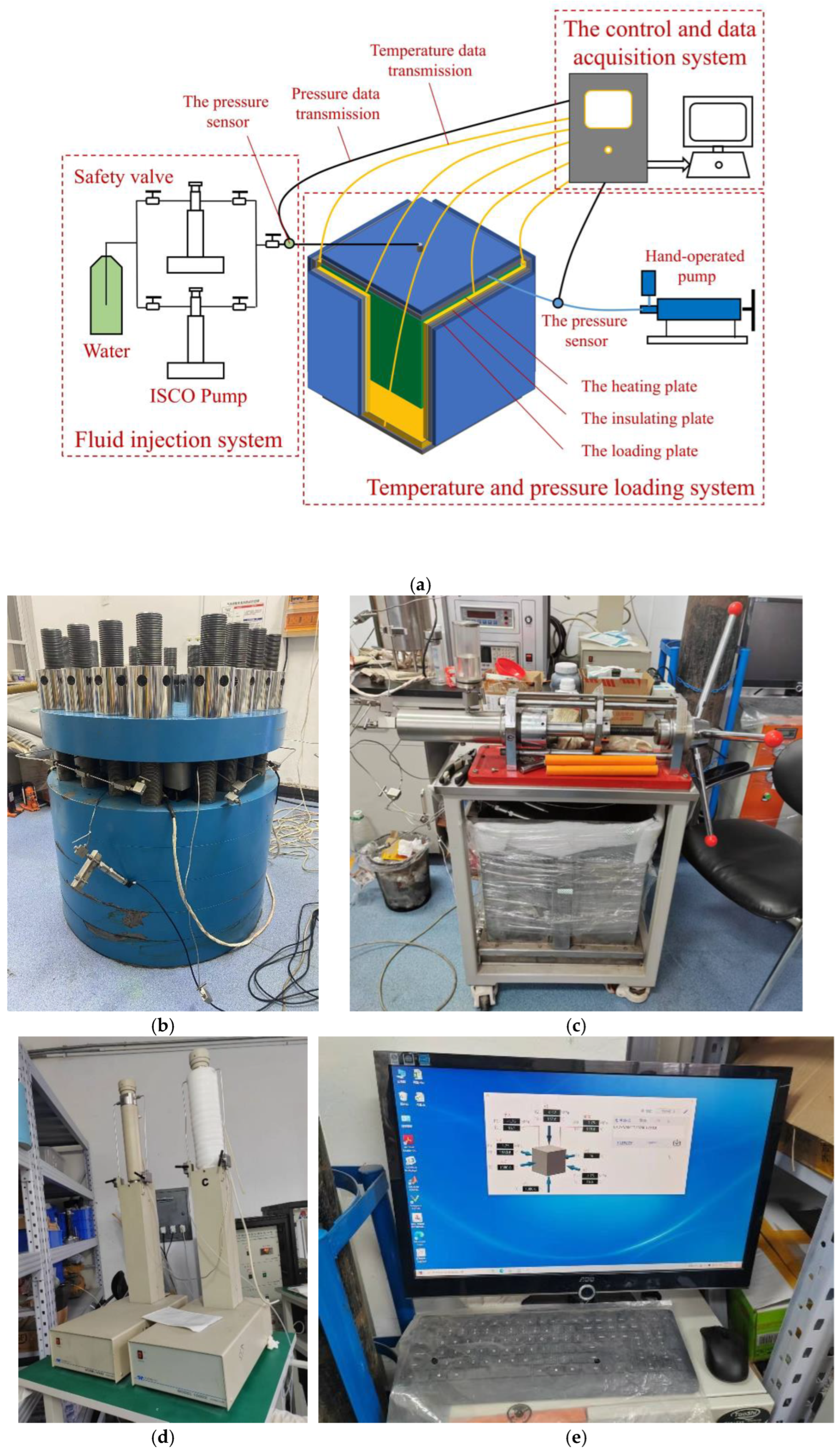
2.1. Large-Scale Model Test Platform
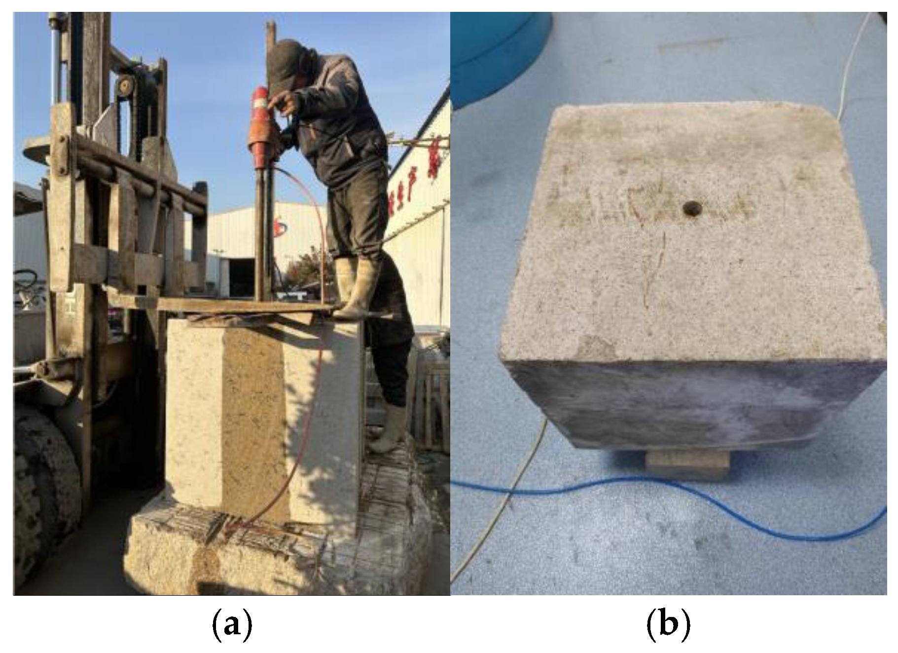
2.2. Sample Preparation
2.3. Test Procedure
3. Experimental Results
3.1. Hydraulic Fracturing
3.2. Deflagration Fracturing
4. Discussion
4.1. Comparison of Fracturing Methods
4.2. Influence of Temperature on Fracturing Effect
4.3. Influence of the Borehole Number on Fracturing Effect
5. Conclusions
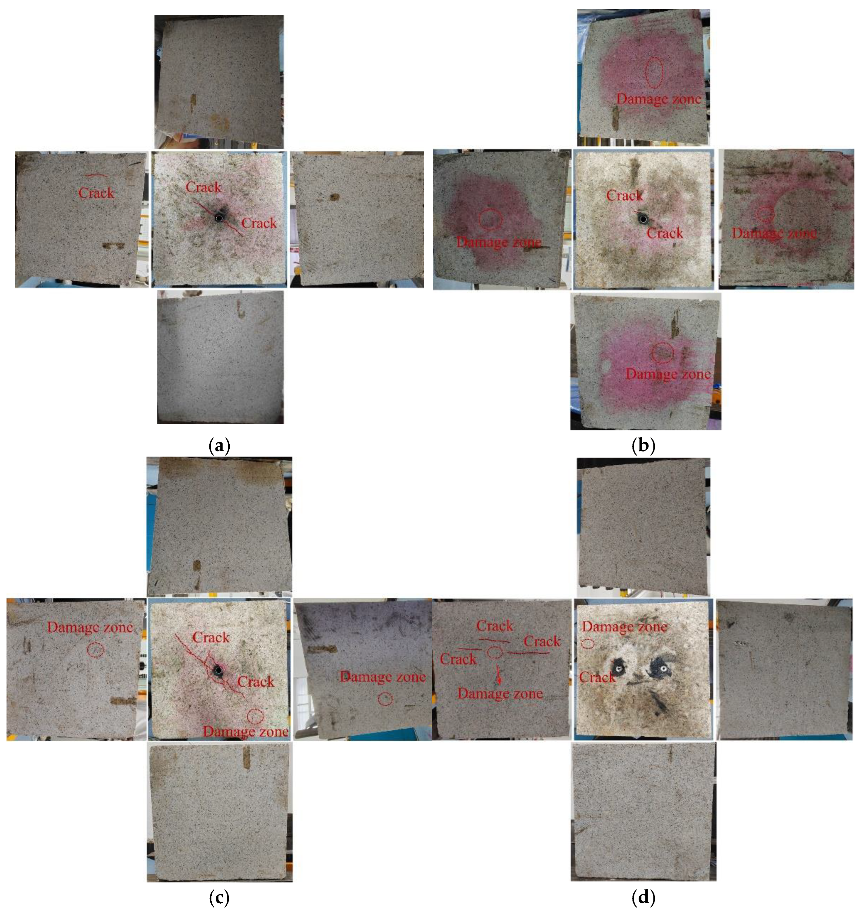
- From the perspective of increasing the reservoir capacity, the rock-breaking effect of deflagration fracturing is significantly better than that of hydraulic fracturing. Moreover, the crack propagation in deflagration fracturing is almost unaffected by the geostress difference resulting from external loads. In contrast, the damage caused by hydraulic fracturing is mainly distributed along the direction of the maximum principal stress.
- Temperature has a significant impact on the fracturing process of granite. Essentially, the microcracks generated within high-temperature rocks change their own mechanical properties, thereby influencing the fracturing process. During hydraulic fracturing, more localized damage zones will emerge in high-temperature rocks, and high temperatures tend to make the cracks produced by deflagration fracturing more regular.
- Compared to a single wellbore, dual wellbores in hydraulic fracturing result in greater internal damage to the specimen. However, for deflagration fracturing, the configuration of dual wellbores exerts minimal influence on the overall rock-breaking effect, beyond enabling directional fracture propagation.
- In summary, within EGS projects, the characteristics of both deflagration and hydraulic fracturing can be combined. Initially, deflagration fracturing can be utilized to create directional main fractures in the fractured section of the reservoir, addressing the issue of hydraulic fracturing, which tends to form main fractures along the direction of maximum principal stress. Subsequently, established and cost-effective hydraulic fracturing techniques can be employed to create more secondary fractures and fracture zones, thereby achieving the purpose of increasing the reservoir storage capacity.
Author Contributions
Funding
Institutional Review Board Statement
Informed Consent Statement
Data Availability Statement
Conflicts of Interest
References
- Li, G.; Wu, X.; Song, X.; Zhou, S.; Li, M.; Zhu, H.; Kong, Y.; Huang, Z. Status and Challenges of Hot Dry Rock Geothermal Resource Exploitation. Pet. Sci. Bull. 2022, 7, 343–364. [Google Scholar] [CrossRef]
- Yin, X.; Jiang, C.; Zhai, H.; Zhang, Y.; Lai, G.; Zhu, A.; Yin, F. Review of Induced Seismicity and Disaster Risk Control in Dry Hot Rock Resource Development Worldwide. Acta Geophys. Sin. 2021, 64, 3817–3836. [Google Scholar] [CrossRef]
- Mindygaliyeva, B. Advances in Hot Dry Rock Engineering for Extracting Heat from Earth: From Permeability Enhancement Strategies to Field Experiences in Enhanced Geothermal Systems (EGS). In Proceedings of the 58th U.S. Rock Mechanics/Geomechanics Symposium, ARMA, Golden, CO, USA, 23 June 2024; p. D022S021R015. [Google Scholar]
- Qin, Q.; Zhou, K.; Wei, B.; Du, Q.; Liu, Y.; Li, X.; Hou, J. Experimental and Simulation Study on Deep Reservoir Fracturing Technology: A Review and Future Perspectives. Geoenergy Sci. Eng. 2024, 242, 213209. [Google Scholar] [CrossRef]
- Lin, Y.; Jiang, J.; Zhu, T.; Ruan, X.; Ding, Y.; Fu, Y.; Sun, F.; Wang, L. Research of cement samples damage and fracture by exploding load. J. China Univ. Pet. 2006, 30, 55–58. Available online: https://kns.cnki.net/KCMS/detail/detail.aspx?dbcode=CJFQ&dbname=CJFD2006&filename=SYDX200603012 (accessed on 14 February 2025).
- Jiang, J.; Lin, Y.; Ding, Y. Experiment research on low permeability reservoir improved by explosion technology. Chin. J. Rock Mech. Eng. 2009, 28, 2830–2835. Available online: https://kns.cnki.net/KCMS/detail/detail.aspx?dbcode=CJFQ&dbname=CJFD2009&filename=YSLX2009S1039 (accessed on 14 February 2025).
- Ma, G.; An, X. Numerical Simulation of Blasting-Induced Rock Fractures. Int. J. Rock Mech. Min. Sci. 2008, 45, 966–975. [Google Scholar] [CrossRef]
- Hu, S.; Pang, S.; Yan, Z. A New Dynamic Fracturing Method: Deflagration Fracturing Technology with Carbon Dioxide. Int. J. Fract. 2019, 220, 99–111. [Google Scholar] [CrossRef]
- Gong, D.; Chen, J.; Cheng, C.; Kou, Y.; Jiang, H.; Zhu, J. Numerical Simulation on Radial Well Deflagration Fracturing Based on Phase Field Method. Energies 2023, 16, 4758. [Google Scholar] [CrossRef]
- Wang, J.; Guo, T.; Chen, M.; Qu, Z.; Liu, X.; Wang, X. Numerical Simulation of Deflagration Fracturing in Shale Gas Reservoirs Considering the Effect of Stress Wave Impact and Gas Drive. Int. J. Rock Mech. Min. Sci. 2023, 170, 105478. [Google Scholar] [CrossRef]
- Yin, Z.; Huang, H.; Zhang, F.; Zhang, L.; Maxwell, S. Three-Dimensional Distinct Element Modeling of Fault Reactivation and Induced Seismicity Due to Hydraulic Fracturing Injection and Backflow. J. Rock Mech. Geotech. Eng. 2020, 12, 752–767. [Google Scholar] [CrossRef]
- Atkinson, G.M.; Eaton, D.W.; Igonin, N. Developments in Understanding Seismicity Triggered by Hydraulic Fracturing. Nat. Rev. Earth Environ. 2020, 1, 264–277. [Google Scholar] [CrossRef]
- Xu, J.; Liu, Y.; Sun, W. Production Simulation of Stimulated Reservoir Volume in Gas Hydrate Formation with Three-Dimensional Embedded Discrete Fracture Model. Sustainability 2024, 16, 9803. [Google Scholar] [CrossRef]
- Elwegaa, K.; Emadi, H. The Effect of Thermal Shocking with Nitrogen Gas on the Porosities, Permeabilities, and Rock Mechanical Properties of Unconventional Reservoirs. Energies 2018, 11, 2131. [Google Scholar] [CrossRef]
- Wu, X.; Huang, Z.; Li, R.; Zhang, S.; Wen, H.; Huang, P.; Dai, X.; Zhang, C. Investigation on the Damage of High-Temperature Shale Subjected to Liquid Nitrogen Cooling. J. Nat. Gas Sci. Eng. 2018, 57, 284–294. [Google Scholar] [CrossRef]
- Sun, Y.; Zhai, C.; Cong, Y.; Zheng, Y.; Tang, W.; Wang, S.; Lai, Y.; Wang, Y.; Chen, A. Pore fracture structure evolution and damage failure mechanism of hot dry rock induced by temperature impact effect. J. China Coal Soc. 2024, 49, 4855–4872. [Google Scholar] [CrossRef]
- Li, X.; Liu, K.; Yang, J. Study of the Rock Crack Propagation Induced by Blasting with a Decoupled Charge under High In Situ Stress. Adv. Civ. Eng. 2020, 2020, 9490807. [Google Scholar] [CrossRef]
- Liao, J.; Cao, C.; Hou, Z.; Mehmood, F.; Feng, W.; Yue, Y.; Liu, H. Field Scale Numerical Modeling of Heat Extraction in Geothermal Reservoir Based on Fracture Network Creation with Supercritical CO2 as Working Fluid. Environ. Earth Sci. 2020, 79, 291. [Google Scholar] [CrossRef]
- Das, I.; Zoback, M.D. Long-Period Long-Duration Seismic Events during Hydraulic Stimulation of Shale and Tight-Gas Reservoirs—Part 2: Location and Mechanisms. Geophysics 2013, 78, KS109–KS117. [Google Scholar] [CrossRef]
- Damjanac, B.; Cundall, P. Application of Distinct Element Methods to Simulation of Hydraulic Fracturing in Naturally Fractured Reservoirs. Comput. Geotech. 2016, 71, 283–294. [Google Scholar] [CrossRef]
- Lin, H.; Yang, H.; Wang, Y.; Zhao, Y.; Cao, R. Determination of the Stress Field and Crack Initiation Angle of an Open Flaw Tip under Uniaxial Compression. Theor. Appl. Fract. Mech. 2019, 104, 102358. [Google Scholar] [CrossRef]
- Lu, J.; Ghassemi, A. Coupled Thermo–Hydro–Mechanical–Seismic Modeling of EGS Collab Experiment 1. Energies 2021, 14, 446. [Google Scholar] [CrossRef]
- Yuan, Y.; Xu, T.; Moore, J.; Lei, H.; Feng, B. Coupled Thermo–Hydro–Mechanical Modeling of Hydro-Shearing Stimulation in an Enhanced Geothermal System in the Raft River Geothermal Field, USA. Rock Mech. Rock Eng. 2020, 53, 5371–5388. [Google Scholar] [CrossRef]
- Huang, L.; Dontsov, E.; Fu, H.; Lei, Y.; Weng, D.; Zhang, F. Hydraulic Fracture Height Growth in Layered Rocks: Perspective from DEM Simulation of Different Propagation Regimes. Int. J. Solids Struct. 2022, 238, 111395. [Google Scholar] [CrossRef]
- Zhuang, D.; Yin, T.; Li, Q.; Wu, Y.; Tan, X. Effect of Injection Flow Rate on Fracture Toughness during Hydraulic Fracturing of Hot Dry Rock (HDR). Eng. Fract. Mech. 2022, 260, 108207. [Google Scholar] [CrossRef]
- Xu, Y.; Zhai, C.; Hao, L.; Sun, X.; Liu, Y.; Li, X.; Li, Q. The Pressure Relief and Permeability Increase Mechanism of Crossing-Layers Directional Hydraulic Fracturing and Its Application. Procedia Eng. 2011, 26, 1184–1193. [Google Scholar] [CrossRef]
- Chen, L.; Zhang, G.; Zhang, M.; Cao, Y.; Shen, L. Propagation process of hydraulic fracture crossing an orthogonal discontinuity. Rock Soil Mech. 2023, 44, 159–170. [Google Scholar] [CrossRef]
- Ma, X.; Wang, G.; Hu, D.; Zhou, H. Hydraulic fracturing of granite under real-time high temperature and true triaxial stress. J. Cent. South Univ. 2023, 30, 243–256. [Google Scholar] [CrossRef]
- Yin, T.; Zhuang, D.; Li, Q.; Tan, X.; Wu, Y. Temperature-Dependent Factors on Hydraulic Fracturing of Hot Dry Rock (HDR): An Experimental Investigation. IOP Conf. Ser. Earth Environ. Sci. 2020, 570, 032023. [Google Scholar] [CrossRef]
- Wu, J.; Liu, L.; Zhao, G.; Chu, X. Research and Exploration of High Energy Gas Fracturing Stimulation Integrated Technology in Chinese Shale Gas Reservoir. Adv. Mater. Res. 2012, 524–527, 1532–1536. [Google Scholar] [CrossRef]
- Chen, D.; Wu, X.; Li, H.; Wu, F. Fracture dynamic extending model for oil formation exploding fracturing. J. China Univ. Pet. 2011, 35, 103–107. Available online: https://kns.cnki.net/KCMS/detail/detail.aspx?dbcode=CJFQ&dbname=CJFD2011&filename=SYDX201104020 (accessed on 14 February 2025).
- Goodarzi, M.; Mohammadi, S.; Jafari, A. Numerical Analysis of Rock Fracturing by Gas Pressure Using the Extended Finite Element Method. Pet. Sci. 2015, 12, 304–315. [Google Scholar] [CrossRef]
- Li, X.; Liu, K.; Sha, Y.; Yang, J.; Ma, S.; Hong, Z. Investigation on Radial Fracturing around Borehole under Combined Static Stress and Blasting. Theor. Appl. Fract. Mech. 2023, 127, 104038. [Google Scholar] [CrossRef]
- Pan, C.; Li, X.; Li, J.; Zhao, J. Numerical Investigation of Blast-Induced Fractures in Granite: Insights from a Hybrid LS-DYNA and UDEC Grain-Based Discrete Element Method. Geomech. Geophys. Geo-Energy Geo-Resour. 2021, 7, 49. [Google Scholar] [CrossRef]
- Huang, B. Numerical simulation for deflagration fracturing reservoir and analysis of well condition influencing factors. Drill. Prod. Technol. 2021, 44, 33–37. Available online: https://kns.cnki.net/KCMS/detail/detail.aspx?dbcode=CJFQ&dbname=CJFDLAST2021&filename=ZCGY202102010 (accessed on 14 February 2025).
- Li, J.; Li, G.; Wang, Z.; Yu, M.; Gao, J. Experimental Study on High-Energy Gas Fracturing Artificial Coal. Appl. Sci. 2022, 12, 11606. [Google Scholar] [CrossRef]
- Li, N.; Zhang, S.; Ma, X.; Zou, Y.; Chen, M.; Li, S.; Zhang, Y. Experimental study on the propagation mechanism of hydraulic fracture in glutenite formations. Chin. J. Rock Mech. Eng. 2017, 36, 2383–2392. [Google Scholar] [CrossRef]
- Xu, C.; Zhang, G.; Peng, Y. Study on the propagation law of hydraulic fractures by cyclic injection in glutenite. Chin. J. Rock Mech. Eng. 2024, 43, 1966–1977. [Google Scholar] [CrossRef]
- Li, L.; Li, G.; Meng, Q.; Wang, H.; Wang, Z. Numerical simulation of propagation of hydraulic fractures in glutenite formation. Rock Soil Mech. 2013, 34, 1501–1507. [Google Scholar] [CrossRef]
- Zhou, C.; Wan, Z.; Zhang, Y.; Gu, B. Experimental Study on Hydraulic Fracturing of Granite under Thermal Shock. Geothermics 2018, 71, 146–155. [Google Scholar] [CrossRef]
- Zhuang, D.; Yin, T.; Zhang, Z.; Aladejare, A.; Wu, Y.; Yang, Z. Experimental Study on the Effects of Chemical or Microwave Treatment on the Tensile Strength of Hot Dry Rock. Renew. Energy 2024, 223, 120039. [Google Scholar] [CrossRef]
- Wang, F.; Konietzky, H.; Pang, R.; Zou, Y.; Pang, B.; Ismael, M. Grain-Based Discrete Element Modeling of Thermo-Mechanical Response of Granite under Temperature. Rock Mech. Rock Eng. 2023, 56, 5009–5027. [Google Scholar] [CrossRef]
- Li, N.; Zhang, S.C.; Ma, X.F.; Zou, Y.S.; Cao, T. Experimental Research on the Effect of Cold Water Injection on the Mechanical Properties and Brittleness of Granite in HDR. In Proceedings of the 53rd U.S. Rock Mechanics/Geomechanics Symposium, New York, NY, USA, 23 June 2019. [Google Scholar]
- Yi, F.; Sun, L.; Gao, J.; Xiong, P.; Li, X. Orthogonal comprehensive balance analysis of deflagration fracturing gunpowder parameters. China Offshore Oil Gas 2020, 32, 106–111+180. [Google Scholar]
- Wu, F. The Kinetic Model and Technology Optimization of HEGF Process. Ph.D. Thesis, China University of Petroleum (EastChina), Qingdao, China, 2010. [Google Scholar]


| Sample No. | Temperature | The Borehole Number | The Mass of Deflagration Agent in Each Borehole |
|---|---|---|---|
| H1 | 20 | 1 | -- |
| H2 | 80 °C | 1 | -- |
| H3 | 150 °C | 1 | -- |
| H4 | 40 °C | 2 | -- |
| D1 | 20 °C | 1 | 10 g |
| D2 | 150 °C | 1 | 10 g |
| D3 | 150 °C | 2 | 8 g |
| D4 | 150 °C | 2 | 5 g |
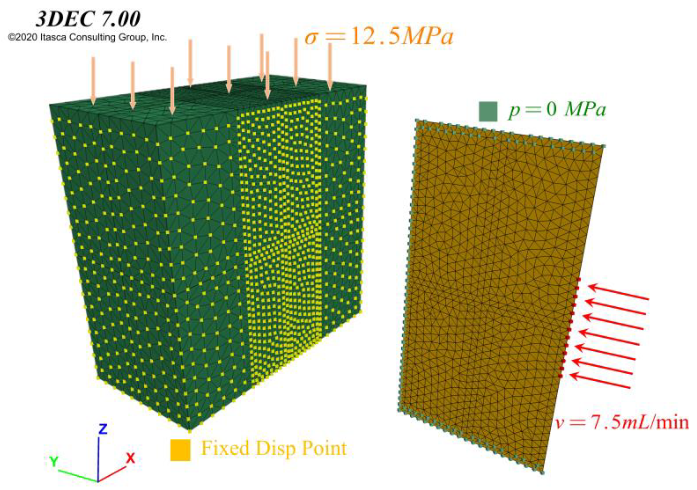
| Parameter Name | Parameter Value | Parameter Name | Parameter Value |
|---|---|---|---|
| Normal stiffness (N/m) | 10 × 109 | Initial/max aperture (m) | 1 × 10⁻⁵/1 × 10−4 |
| Shear stiffness (N/m) | 10 × 109 | Fluid bulk modulus (Pa) | 2 × 10⁵ |
| Cohesion (Pa) | 1 × 10⁹ | Fluid density (kg/m3) | 1000 |
| Tensile strength (Pa) | 1 × 10⁴ | Viscosity (pa·s) | 1 × 10⁻³ |
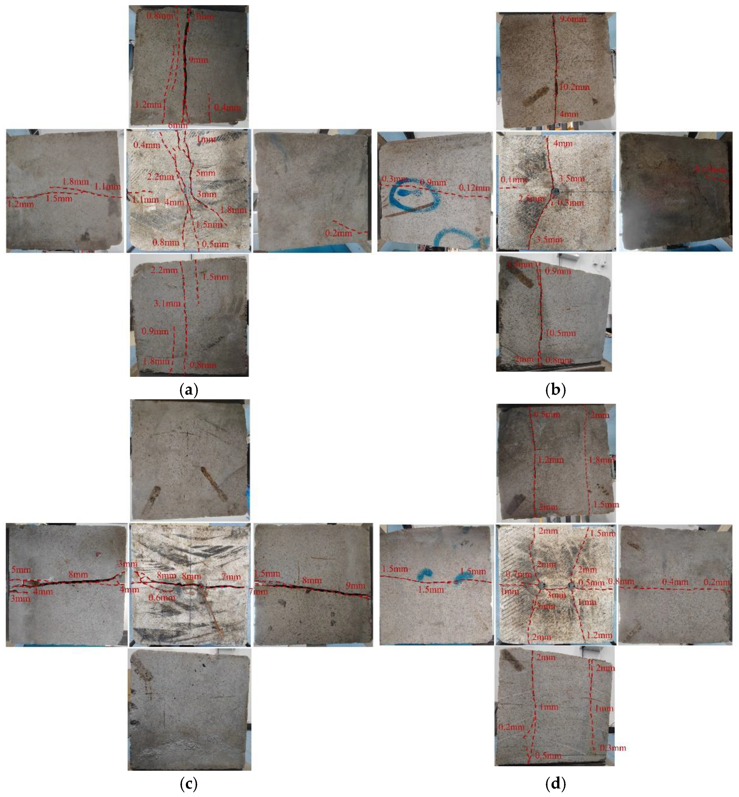
| Fracturing Methods | a/cm2 | b/cm2 | c/cm2 | d/cm2 | Average Area/cm2 | Average Width of Crack/mm | Total Fracture Space/cm3 |
|---|---|---|---|---|---|---|---|
| Hydraulic fracturing | 5620 | 2936 | 1677 | 4989 | 3805.5 | 1.5 | 570.8 |
| Deflagration fracturing | 630 | 207 | 1061 | 973 | 717.75 | 0.05 | 3.6 |
Disclaimer/Publisher’s Note: The statements, opinions and data contained in all publications are solely those of the individual author(s) and contributor(s) and not of MDPI and/or the editor(s). MDPI and/or the editor(s) disclaim responsibility for any injury to people or property resulting from any ideas, methods, instructions or products referred to in the content. |
© 2025 by the authors. Licensee MDPI, Basel, Switzerland. This article is an open access article distributed under the terms and conditions of the Creative Commons Attribution (CC BY) license (https://creativecommons.org/licenses/by/4.0/).
Share and Cite
Yang, H.; Zou, Y.; Bai, B.; Ci, H.; Zhang, T.; Zheng, Z.; Lei, H. Comparison of Hydraulic Fracturing and Deflagration Fracturing Under High-Temperature Conditions in Large-Sized Granite. Appl. Sci. 2025, 15, 2307. https://doi.org/10.3390/app15052307
Yang H, Zou Y, Bai B, Ci H, Zhang T, Zheng Z, Lei H. Comparison of Hydraulic Fracturing and Deflagration Fracturing Under High-Temperature Conditions in Large-Sized Granite. Applied Sciences. 2025; 15(5):2307. https://doi.org/10.3390/app15052307
Chicago/Turabian StyleYang, Hengtao, Yan Zou, Bing Bai, Huiling Ci, Tiancheng Zhang, Zhiwei Zheng, and Hongwu Lei. 2025. "Comparison of Hydraulic Fracturing and Deflagration Fracturing Under High-Temperature Conditions in Large-Sized Granite" Applied Sciences 15, no. 5: 2307. https://doi.org/10.3390/app15052307
APA StyleYang, H., Zou, Y., Bai, B., Ci, H., Zhang, T., Zheng, Z., & Lei, H. (2025). Comparison of Hydraulic Fracturing and Deflagration Fracturing Under High-Temperature Conditions in Large-Sized Granite. Applied Sciences, 15(5), 2307. https://doi.org/10.3390/app15052307