Article

Multiple-Valued Logic, Vocabulary Structure, and Linked List for Data Verification in Dialog Communications of Agents

P.N. Lebedev Physical Institute RAS, 119991 Moscow, Russia
Appl. Sci. 2025, 15(5), 2427; https://doi.org/10.3390/app15052427
Submission received: 25 November 2024 / Revised: 23 December 2024 / Accepted: 13 February 2025 / Published: 24 February 2025
(This article belongs to the Special Issue Blockchain and Intelligent Networking for Smart Applications)

Abstract

:

Featured Application

The proposed method of logic data verification is aimed at the simplified integration of a robotic agent into a local network, even if this agent has incompatible or missing components in the model. Dialog data verification and data exchange schemes use the coded structure of vocabularies, describing system parameters and logic variables, which are supported by the logic language of communications and the dialog protocol for phrase procession.

Abstract

Distant verification of the autonomous agent’s parameters in the dialog mode is a difficult multi-parametric task if the large-scale scene of action is characterized by a large number of collaborative and rival robots. The possible scheme to realize it for mass robots is to use non-exhaustive and selective data verification, combining the polling of internal subsystems and external data storage in collaborating network agents. Selective extraction of data for such checks is proposed to involve the special ordered set of vocabularies, containing coded digital words and classifying parameters of agents, tasks, objects, and events. The structure of such vocabularies is to be combined with various versions of the linked list scheme, known in blockchain and actual for protective documenting of critical data. Multiple-valued logic is used here as the convenient method to provide autonomous navigation in a multi-parametric structure of data and verification variables.

1. Introduction

Modern research in civil robotics includes at least such fields (see Figure 1) as unmanned logistics and Internet of Vehicles (IoV) [1], power grids with smart metering [2], “smart” city [3], autonomous robotic manufacturing [4], Internet of Things (IoT) [5], and medical nursing [6]. The general goal of these investigations, which are based on artificial intelligence (AI) concepts of agents and multi-agent systems (MASs), is to imitate human abilities and to design autonomous and self-sustaining large-scale robotic systems which can operate in wide space-and-time bands without permanent human control. However, the design of autonomous robotic agents is a complicated task, and the development of such systems involves the whole spectrum of conjugated technologies, including the research of modern mathematics [7,8], 5/6 G Internet [9], microprocessors [10], neural networks (NNs) [11], fuzzy logic and controllers [12], computer vision [13,14] and speech procession [15], big data procession [16], traditional and post-quantum cryptography [17], quantum key distribution [18], and quantum computing [19]. The design, debugging, and modification of autonomous agents include autonomous data verification and correction of errors, caused by natural factors or cheaters [18].
As the number of autonomous mobile robots unavoidably grows larger, the designers of IoV systems already propose special network tools and devices to control the growing data traffic and to provide data security [17,18,19,20,21,22]. However, the number of service, industrial, and IoT robots is also expected to enlarge the overall data traffic, and the resulting “burst” of the volume of information and involved control parameters [23] creates new control and verification tasks.
The final goal of any type of verification procedures in agents is to exclude possible incidents and crashes caused by errors, faults, attacks, and illegal data modifications [24,25,26]. An ideal verification method should take into consideration all possible vulnerabilities of agent’s architecture, hardware, and software. It also should take into account current tasks, situation in the scene of action, the trust level of data sources, processed materials, characteristics of objects, and the workload. However, the problem is also to create and support the reliable referent (or template) model for data verification, as attacks can be aimed not only at agents but also at collective resources. One of the possible schemes here is to use verification schemes with the selective extraction of reference content from the distributed structure of local data storages, using free memory resources in loyal robots and network nodes. A holistic formal model for such procedures should additionally integrate data taken from distributed ledgers, partially reproducing the linked list (LL) scheme known in blockchain [27,28] for data protection from illegal modifications. These new options are to complement the known data verification methods reviewed further.

1.1. Verification Tasks and Methods in Modern Robotics

In the review [7] covering more than 150 papers published in 2008–2018, an analysis was performed of formal specification and verification methods for individual and collective robotic systems. The specification was considered as the mathematical description of necessary actions for hardware and software components of the robotic system that do not consider the method of realization but can verify processes. Many mathematical aspects of the problem were analyzed, e.g., set–theoretic methods, logic methods of dynamic verification of hybrid systems, temporal logics, timed automata, robots communication languages, agent programming languages, finite state machines, state machines, Petri nets, probabilistic methods, Markov networks, Büchi automaton, model verification tools, and ontologies. The review [7] also covered models of physical environment, certification and trust indicators, and external and internal threats. Finally, the emphasis was made on the necessity to design integrated formal methods (iFMs) for the specification of agent’s tasks, and the enlarging need was accented for the heterogeneous sets of formalisms for complicated systems description, where each one is responsible for its specific component. One more actual problem is the lack of methods to monitor the interrelation between the specification and the executed software code [8]. The authors of one review [8] expressed the hope that the research in this field will help to create Integrated Verification Environment.
The practical realization of the concept of the heterogeneous sets of formalisms in the route verification method was demonstrated in [29] for the cosmic robot curiosity. Other publications have accented the set of actual aspects in formal verification schemes for robotic collectives; here, one should note that the specifics of quantitative [30,31] and qualitative [32,33] models differ. Active research is being held in such fields as predicate systems modeling [30], temporal logic [33,34,35], and epistemological extensions [36]. Also, one can see publications devoted to discrete relational models [37], state-based models [35,38], and beliefs-based ones [37]. Good results were obtained with the help of domain-dependent embedded models [39], which now can use tools of MATLAB R2024b [40]. One should note the trend to design dynamic and non-exhaustive verification methods [8].
In the field of verification models for collective robotic systems, the detailed review [8] has also emphasized the following spectrum of problems:
  • The use of too general estimation parameters and the absence of methods to take into account the specifics of the domain knowledge,
  • The absence of realistic schemes to evaluate the applicability of the chosen criteria,
  • The lack of specialized languages to model domain knowledge,
  • The insufficient development of methods for runtime verification.
Among other significant gaps, the authors of [8] also pointed out the lack of real possibilities for quantitative specification, i.e., inability of known languages to describe the desired properties of the system. Due to the inhomogeneity of the agent’s structure, the languages for robots’ behavior description should provide both the discrete and the continuous modeling of dynamic processes. They are used to model stochastic and epistemological characteristics of agent interaction with the environment and its users. The gap is too large between quantity indicators for intermediate and final test results. Some other publications accented the need for methods to analyze as probabilistic and stochastic processes [41], such as discrete [42] and continuous dynamic processes in systems of agents [43]. In one paper [44], the emphasis was placed on the fact that namely system description languages should track combinations of stochastic and continuous processes. A very substantial drawback is the lack of public technologies for checks and tests [31,37,45], and complicated systems with the detailed structure description now do not have the appropriate tools for the model-based testing [39,46] and the run-time verification [35,43]. Based on the content of [8,47,48], one comes to the conclusion that there is a very small number of developments for industrial verification and specific knowledge domains.
During 2020–2024, one can see the drastic increase in interest in the practical applications of drones, and impressive publications were devoted to delivery systems, routing, navigation, and verification of real autonomous devices [47,48,49,50,51,52]. For example, a method was proposed in [49] for verifying the operation of a drone during its task execution, using the knowledge base and rules. In [51], a system was proposed for the capturing of illegal drones using computer vision and trajectory prediction system. The authors of Reference [52] discussed the requirement to apply the multi-level architecture in the heterogeneous system of agents. Nevertheless, none of these papers proposed the holistic structure of control parameters, uniting sensors, actuators, decision-making rules, and tasks within the resulting robotic world model (WM) [53], which is the final set of formal expressions and subroutines activated for the current situation. The authors of Reference [53] made their contribution by designing explicit dimensions of WMs, determining the underlying principles to make decisions, and searching the trade-off model for conflict situations. But the conclusion was offered in Reference [53] that the universal WM does not exist, as it highly depends on the robotic system, expert knowledge, the given task, and the environment in which the agent operates. Even a simple robot can use more than one WM, e.g., one for navigation and another one for manipulation. Thus, the imitation of human abilities in verification procedures for robotic agents unavoidably needs to involve multi-parametric models, describing the branched holistic structure of parameters, describing the robot and the scene of action.
An interesting aspect was touched upon in [50], where the hybrid coding with blockchain components was used for network data protection and routing methods in delivery drone systems. In its turn, smart power grids [54] with advanced nodes have combined the autonomous trust estimation of neighbor nodes with the blockchain components. The task here was to protect collected data from modification by cheaters, and the designed grids have demonstrated the ability to detect unscrupulous network users by means of the dialog data exchange between smart nodes. Here, network “witnesses” were involved in the verification of credentials and authorities, and their task was to estimate the trust level (i.e., the reputation coefficient) [54] of neighbor nodes. Thus, this paper has demonstrated the reasonable extension of the blockchain scheme [54,55,56] into new application fields.
Blockchain [54,55,56] is the method initially designed for cryptocurrency mining, and its goal is to prevent illegal data modifications in a group of highly motivated users. It sustains the distributed set of copies in participating network nodes, which are protected by standard network data protection tools and hardly can be quickly and massively modified by others in a way that would go unnoticed. Blockchain uses the linked list (LL) or the ledger scheme, which is in fact the sequential mixed set of data taken from different notations. Here, the first of notations is to be mixed with the second one, and further, the second one is to be mixed with the third one, and so on. However, the traditional blockchain scheme was initially intended for mining and is too complicated to be directly used in mass robotic agents equipped with low-throughput platforms.

1.2. Dialog Data Exchange in a Collective of Network Agents

The distant verification procedure in a collective of autonomous network agents imposes the task to determine actual parameters of the complicated robotic device, which in its turn imitates dozens of basic human abilities [57]. Such a task is vast and differs from traditional system identification tasks [58] and model-checking methods in computing [59,60,61]. Here, the autonomous agent is supposed to have AI algorithms, own tasks, goals, beliefs, etc., and it does not require intensive transfer of comprehensive instructions. Here, the details of the agent’s work or its positioning are typically not very interesting for the distant administrator, as they should be controlled by the autonomous robot itself. Control procedures for advanced robots are expected to be displaced to generalized parameters, including the approval of received licenses, agent’s authenticity, checks of data integrity, space-coordinate confirmation, and the verification of passed routes and cargo parameters [26]. Nevertheless, one should use initial debugging, periodic tests, checks after learning and self-learning sessions, and upgrading and data restoration procedures [6,7,8]. Actual tools are the biometrics of human administrators and checks of such digital “fingerprints” of robots, such as parts’ numbers, used random and one-time paroles, and the prehistory of earlier work performed [26]. However, human experts remain the final instance.
As complicated errors and faults may need the sequence of data and instruction transfer sessions, one should imitate the human ability to hold dialog conversations, which are needed to design some formal language models with a large data capacity. The known adequate scheme of a formal dialog interaction between two agents was formalized, e.g., back in 1987, by T. Winograd and B. Fosser, in their book [62]. Further research has included, e.g., such development as the first version of NesC software [63], which was intended for the Tiny OS system. This method was based on the adapted version of C programming language and provided parallel procession in agents. Further reviews of language models can be seen in [64]. The modern trend in language systems is represented mainly by ChatGPT v. 3.5 [65]. But this language tool uses complicated software and scarcely can be easily adapted to verification tasks in mass microcontroller platforms intended for low-traffic interaction and adaptable to specific requirements of the individual user. For highly specialized agents, there is no point to install any too powerful neural networks designs, as the spectrum of items for “conversations” of robots seems to be limited.
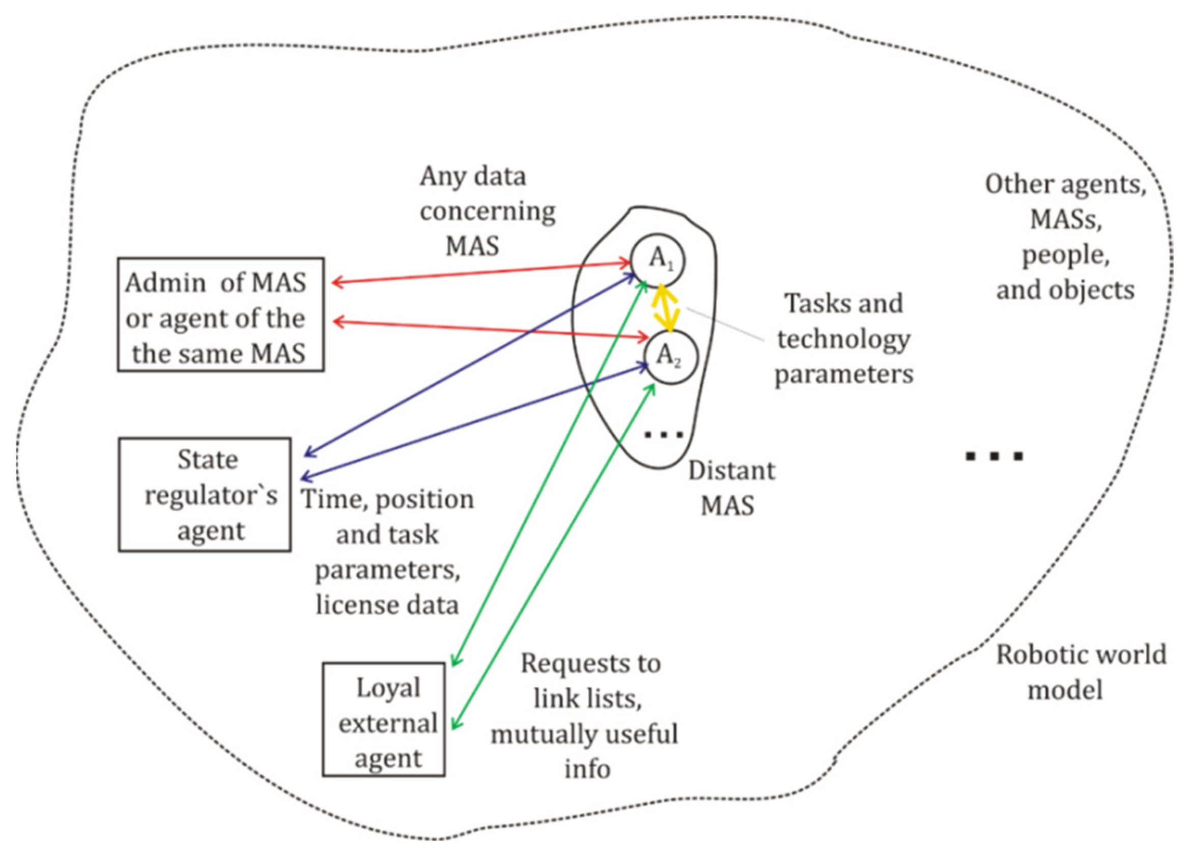
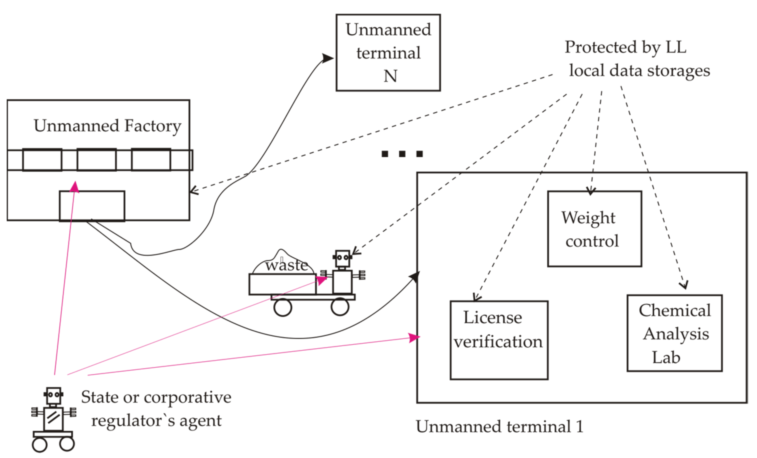
The typical basic set of dialog communications for mass agents is shown in Figure 2, where robotic agents from some allocated MASs are supposed to carry out work in a space scene of action, including various individual partner and rival robots, MASs, people, animals, buildings, vehicles, and other objects. All of them are supposed to be recognized by a computer vision system [13,14] or LIDAR [66,67]. Here, for the sake of simplicity, we do not consider dashcam videos, which are a useful tool for verification but need massive AI-based image procession. The agent in the allocated MAS can interact with its administrator, which is used to support the distant work of the agent and should verify some of its parameters in a planned mode or during the correction of the robot’s behavior. The agent is supposed to exchange all possible communication messages with the administrator (marked by red arrows) and to use limited data sets in dialogs with other agents of the same MAS (shown by yellow arrows). In the last case, messages can mainly include parameters of the scene and tasks. Also, the scene of action imposes the presence of mobile or static agents of corporative and state regulators [26], checking licenses, payments, and technical parameters of robots. Agents of MASs should typically exchange with them by using the limited set of formal messages (marked by blue arrows). The verification method also should take into account possible data exchanges between the agent of some MASs and loyal external agents or network nodes [26,68] involved by mutual services or a rent. The data flow between such pairs of robots (marked by green arrows in Figure 2) can contain requests to send some necessary data or tools, or to write/read notations in the distributed copies of LL protected data storages [68,69]. Potentially, people in the scene also can communicate with robots concerning positioning, parking, and other common problems, using special tools for the translation of robotic messages to people and vice versa. Another aspect of the dialog man-agent is the necessity to combine human checks with fully automatic ones in the case of attacks and faults. For mass robots, automatic and human procedures are preferable to using universal formal notations and code representations in order to reduce expenses. However, the automatic verification may need more detailed and precise description of parameters, as modern agents cannot make generalizations and analogies like human beings. Thus, even minimalistic consideration of the scene of action demonstrates the necessity to describe the branched structure of communicating participants and options in the dialog protocol.

1.3. The Methodology and the Possibilities of Multiple-Valued Logic Modeling

Multiple-valued logic (MVL) [70,71] operates with logic variables, using K discrete truth levels instead of 2 ones in the Boolean logic. MVL calculus has been known for a long time [70,71,72], and many of its historical aspects one can see in the collection of articles [70]. This book has presented discrete complete systems of logic operators, known as systems by Lucasievich, Rosser–Terkett, Post, Walsh, and Allen–Givone. Formal MVL calculus was also presented, e.g., in [70,71,72], and discrete Allen–Givone algebra (AGA) was discussed in detail in the paper [73]. MVL discrete systems were associated with the attempts to raise the density of the processed information in chips per a logic gate [70]. Besides microelectronics, there were attempts to use discrete MVL for the realization of Kripke structures [59,60,61] for temporal logic and model checking tasks; however, that has proved to be too complicated for practice models. Also, MVL was used as a tool to raise the density of transferred information in laser and fiber optics lines [74]. However, more simple and accessible technologies finally have provided the priority of the Boolean logic. Nevertheless, further considered papers [68,69,73,75] demonstrate many useful properties of MVL models that can be used for network agents. As AGA logic expressions and models are can be easily and conveniently calculated in parallel [75], this calculus is especially interesting for modern optoelectronic scheme design. Also, the advantage of MVL over binary is being discussed to give advantages to quantum computing [76].
Further, we do not discuss possible designs and applications of AGA logic gates; we consider only its software emulation. The intricacy here is that any logic calculus can obtain success only when combined with supporting technologies; for example, the representative graph analysis for the MVL model used in [59,60,61] for temporal logic modeling scarcely can be used for real multi-parametric robotic system with the large number of noise factors, probabilistic, and approximate patterns for the description of people, technical objects, and their faults. But this problem seems to be partially bypassed by the integration of traditional precise, probabilistic, and approximate calculations being held within MVL, Boolean, and fuzzy logic. One should especially note that some publications unreasonably confuse fuzzy logic and the discrete MVL, taken with the large number of truth levels. But inference rules and membership functions from fuzzy logic [75,77] can be independently described by AGA, which also was shown to model the discrete analog of the fuzzy controller with parametric T-gates (or T-norms and T*-conorms) [77]. Regardless, all of these models were produced by the human intellect, and all their combined applications also should be modeled within AI methods. That reason explains the proposal to use the heterogeneous logic architecture of agent [75], which is the tool to simplify the joint use of various logic models in multi-parametric modeling, controlled by AGA-based schemes.
The motivation to use AGA for the design of applied systems in the present paper is based on several earlier obtained results. As was discussed in [69,73,75], AGA gives the possibility to construct high-data-capacity multi-parametric logic functions, where for a function with n variables and K truth levels, the number of rows in the truth table enlarges as K K n instead of 2 2 n in the Boolean model. In order to design multi-parametric data procession and verification models, the presented paper involves AGA’s complete set of logic operators [70], taken with a large number of truth levels (k ≥ 256) [69,73,75], making it especially convenient for the design of large-scale data structures in network robotics. Namely, this property was used in an AGA-based secret coding scheme [73], reproducing the classic one-time pad secret coding method [18] with the help of quantum random number generator (QRNG) [78]. The cheaper alternative is to use the AGA version of the random oracle scheme [79], involving QRNG and the special algorithm to write down the set generated by QRNG one-time random keys. Further research on AGA-based optoelectronic data coding and protection methods has proposed the combined classic and quantum protocol [69] for position-based cryptography tasks. Besides this, two classic algorithms were designed for the distant comparison of confidential parameters, without their disclosure [77], based on AGA and random oracle procedures, and they did not need special cryptography software.
The abovementioned two classic algorithms were the motive to consider further methods for the long storing of confidential data in distant agents. Illegal data modification is the well-known problem for classical cryptography systems; the attacker can do it in a distant node, located out of the trusted zone [18]. A possible solution was prompted here by blockchain scheme [54,55,56] for cryptocurrency mining, where the principle of LL was used. As the basic LL method is too complicated to be used in mass robotic platforms, the AGA-based version of LL [68,69] was designed. It was proposed for agents and loyal network nodes, possessing limited free memory resources. As verification tasks do not always need large traffic and capacity of data storage, they may involve the distributed set of limited free memory resources. A possible variant here is to use low-capacity data storages created in collaborating network agents and loyal network nodes, which in fact are to be used as external “witnesses”. However, the problem here is to create an auxiliary low-traffic local network, excluding the penetration of illegal code from Internet into agents. Besides additional data channels, it is preferable to use a special communication language, incomprehensible to other modules. Earlier designed template-matching AGA procedures [75] encouraged using it for the design of the special dialog protocol, presented further for data exchange in a local network of communication modules of agents. It includes the formal logic language for dialog interaction of agents that is based on vocabulary structure, describing terminology of the robotic system by means of special secret codes. The proposed further protocol is the method to unite verification procedures, data coding schemes, and local confidential storages under the holistic system for reliable data exchange and checks, combining basic agents and collaborating external robots. Here, the final goal of research is to design a comprehensive set of AGA-based algorithms for the realization of an autonomous agent and to find the reasonable trade-off between AGA and traditional Boolean methods.

1.4. The Aim of the Paper

As follows from the given abovementioned literature review, the verification method for modern robotic agents should provide a vast set of properties:
The formal model for verification in the robotic system should have high capacity and describe in detail the properties of a large-scale collective of agents;
Verification procedures should be integrated into the holistic model of the scene of action, describing robots, tasks, people, and various objects;
The interaction of agents is to provide dialog mode of communications, where formal language phrases can be continued and should use content-based addressing, excluding disclosing of physical addresses in data storages;
The model of system description should be unified for various platforms, including simple 8-bit ones;
Reference data for verification procedures are to be written to protected local data storages, using LL scheme and unpredictably located in collaborating devices;
As AGA multiple-valued logic calculus provides a substantial set of tools for data coding in large-scale systems of agents, it should be used in verification procedures.
The goal of the presented paper is to propose the following set of actual solutions based on AGA calculus:
  • To design new AI procedures for a robotic agent, based on AGA;
  • To create the holistic and the detailed formal logic structure of parameters, terminology, and coded logic variables for further modeling of autonomous agents;
  • To propose AGA-based communication language, convenient for extended dialogs of agents in scalable large-scale robotic system;
  • To adapt the LL scheme to minimalistic local data storages in collaborating network agents and to provide integrity checks of transferred messages;
  • To provide the clear control of verification schemes within the heterogeneous logic architecture of agent.
For the realization of the abovementioned goal, the presented paper combines several tools:
High-capacity logic modeling method, based on AGA;
The ordered structure of coded vocabularies for the comprehensive description of terminology, objects, and events in the multi-parametric logic model, operating with large space and time bands;
The formal AGA language for robot’s communications and phrase design;
The adaptation of AGA-based LL for verification in low-throughput platforms.
Further, Section 2 contains MVL basic mathematical tools; Section 3 proposes AGA representation of the vocabulary structure and the communication language; Section 4 is devoted to adapted verification schemes, based on LL; and Section 5 presents the fragmentation scheme of AGA functions for human checks. Section 6 discusses microassembler modeling and supporting platforms. Section 7 discusses the main restrictions of AGA models.

2. Method: Basic Multiple-Valued Logic Model

AGA data coding and data verification methods typically complement other known data protection methods and schemes to prevent illegal data modifications. The presented materials follow the known methodology of cryptography and data leakage-protection schemes, using only basic models and proven algorithms that are clear for analysis. They should be initially disclosed for common access and public search of vulnerabilities. Proposed new AGA methods are, in essence, clear for such analysis due to the structure of AGA logic calculations. That can be used further as a platform for the design of applied AI data procession technologies.
According to the earlier proposed heterogeneous logic architecture of an agent [75], AGA is considered a tool to design a multi-parametric logic model for the description of the scene of action and verification procedures.

2.1. Multiple-Valued Allen–Givone Algebra

As in earlier publications [26,68,69], we consider basic definitions of MVL according to [70], where the discrete K -valued AGA calculus operates with discrete MVL functions, y = f x 1 , , x n , which is given for n input variables, x 1 , , x n , and one output variable, y . It is very handy for multi-parametrical modeling in AGA that variables and an arbitrary function, y = f x 1 , , x n , can have K discrete truth levels from the finite set of natural numbers, i.e., x 1 ,   x 2 , , x n , y L = { 0,1 , ,   K 1 } . Here, 0 responds to the absolute false value, and k 1 indicates the absolutely true one. The complete set of AGA operators [70] given by expression Eq. (1)
< 0 , 1 , , K 1 , X a , b ,   , + >
guarantees the representation of an arbitrary logic function, y = f x 1 , , x n , by using the following:
  • Logic constants 0 ,   1 , , K 1 ;
  • Operators Min( x i , x j ) or   , marked by * , selects the minimal truth level in the pair x i and x j ;
  • Operators Max( x i , x j ) or , marked by +, selects the maximal truth level in the pair x i and x j ;
  • Operators Literal X ( a , b ) , given by Eq. (2):
    X a , b = 0 ,   i f   b < x < a K 1 ,   i f   a x b
    where for any X(a, b), always b a , and a , b   L = 0,1 , , K 1 .

2.2. Possible Discrete Scales for Mapping of Truth Levels

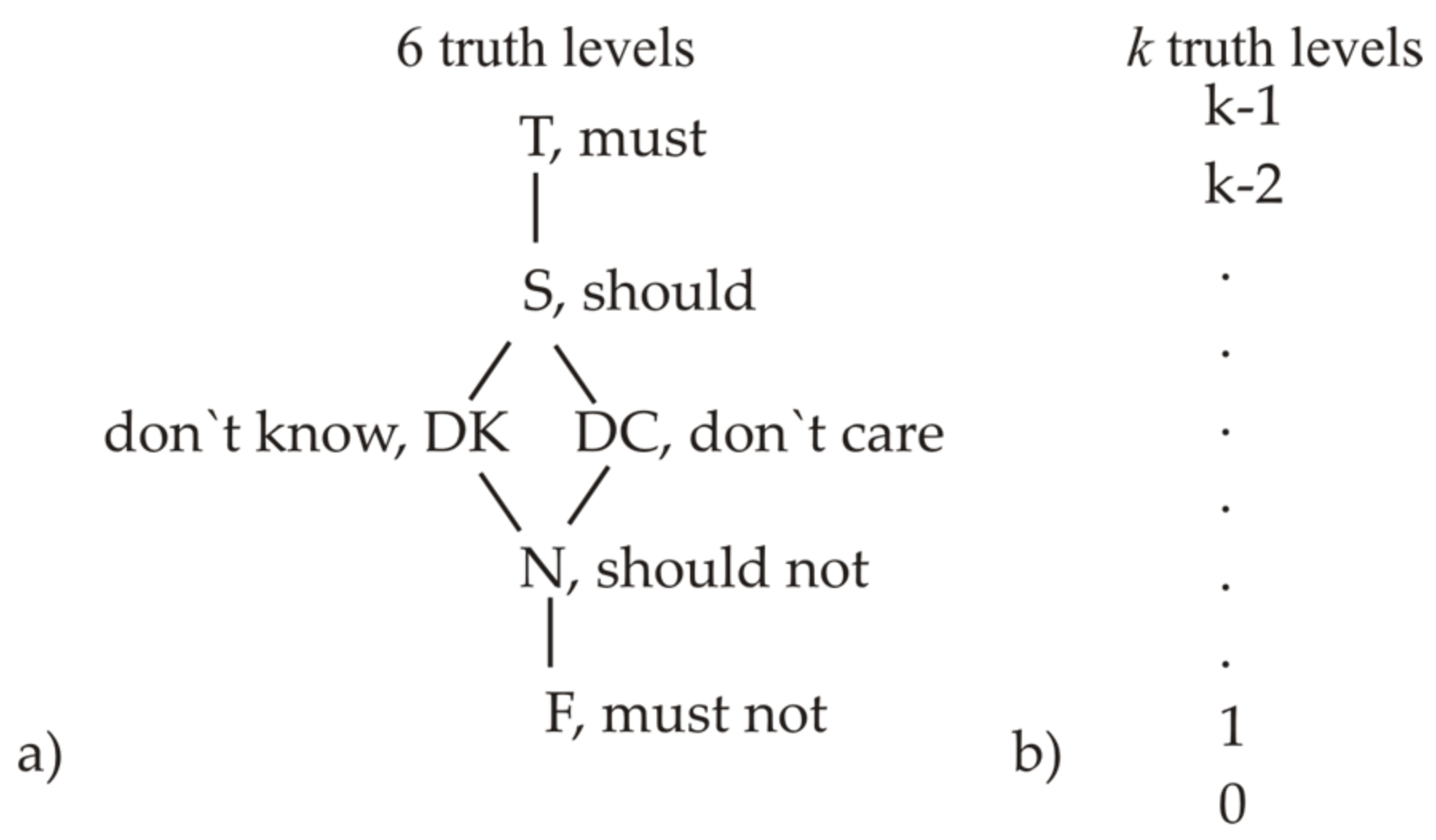
All truth levels in AGA (see Figure 3a) are to be processed and compared according to the scale   0 ,   1 , , K 1 , [70], which belongs to the class of lattices, where all levels are comparable. But principally, MVL may be given differently; for example, in [60,61], the 6-level logic was defined with two non-comparable elements “don’t know” and “don’t care” for the scale shown in Figure 3b. Such a model was designed for model checking by means of temporal logic and Kripke diagrams [60], and, in fact, it included both positive and negative estimations of truth levels. However, in other papers by these authors, this system has given a complicated and non-visual method of checks. In contrast to it, the proposed further method is intended for the heterogeneous logic architecture of agent based on AGA [70] and uses simple scale with the large number K of all comparable truth levels. It can exceed 256 ones and one may use the full capacity of standard 8, 16, 32 … bit memory registers for the emulation by microprocessors [80]. Here, the axis with truth levels is the scale for mapping of various subsets of physical and model parameters, and we interpret the truth level as the ordered affiliation of different variables and corresponding mapped objects to the holistic agent’s model, as well as the tool to classify parameters. Involved logic parameters may respond to incomparable physical properties (e.g., red and triangle), which should be described by various logic variables mapped of the truth scale given in Figure 3b. Principally, one can use nonlinear mapping onto the scale of truth levels, actual for wide-band space systems or long-term time control. It can complement the method of correlated variables discussed in Section 2.4.

2.3. Formation of AGA Functions

For holistic or fragmented MVL modeling, one should use traditional and universal representation of MVL function by the truth table [70] shown in Table 1. MVL function y = f x 1 , , x n has the overall number of raws, K n 1 , in contrast to Boolean logic, with its only 2 n 1 rows. The column for the output variable f x 1 , , x n should be filled in by logic constants, C = { 0 ,   1 , , K 1 } , according to expert choice or some formal model. Every row of such truth table with the nonzero value of the output variable F , , has equivalent representation by a product term [70], written via logic constants and operators from Eq. (5).
Any arbitrarily given truth table always guarantees the possibility [70] to obtain correct formal Eq. (3):
y = F ( 0,0 , , 0 ) X 1 ( 0,0 ) X 2 ( 0,0 )   X n ( 0,0 ) + + F 0,0 , . . . , 1 X 1 1,1 X 2 0,0   X n 0,0 + + F ( K 1 , K 1 , , K 1 ) X 1 ( K 1 , K 1 ) X 2 ( K 1 , K 1 )   X n ( K 1 , K 1 ) .
In this equivalent representation of the truth table, every row is represented by the product term F(0,0,…,0)* X 1 ( a 11 , a 11 )* X 2 ( a 21 , a 21 ) . . .   X n ( a n 1 , a n 1 ) , containing Literals operators X ,   and their lower and higher indexed parameters, a,b [qurep, Apl Sc]. Notation X j q , q   means that this Literal is nonzero only for one natural number q = a = b . In Eq. (3), Literals X , are to be filled in by parameters a = b , taken from the corresponding row and column of the truth table. During minimization procedures [70], values of a ,   b can be modified. The calculation time depends on the real number of all non-zero parameters a ,   b .
For calculations and memory storages, AGA functions can be equivalently written by matrixes Eq. (4), formed by indexed pairs of Literal parameters, ( a i , b i ) ,   i = 1 , , n , and logic constants, C = 0 ,   1 , , K 1 :
A = a 11 a 1 n a K n 1,1 a K n 1 , n , B = b 11 b 1 n b K n 1,1 b K n 1 , n ,   C = c 11 c 1 v c K n 1,1 c K n 1 , v
Here, n is the number of input variables, and K is the number of truth levels. The switching function in AGA guarantees the output only of data, written in the truth table or in equivalent logic expressions, and can output error only if it was illegally or not correctly modified.

2.4. Correlated Variables for the Description of Large-Scale Space and Time Bands

Mobile agents should imitate the human ability to estimate time, space, light intensity, and some other parameters in wide bands of values and with various precision (e.g., from micrometers to thousands of kilometers). In order to obtain a wide range of measurements, to avoid too-large numbers of truth levels ( K ), and to use cheaper hardware, one can use the method of correlated variables. It helps to combine in one AGA logic expression data, describing the same physical parameter with various precision of data in the same function. The description of, e.g., position   x = 2830 m for the space axe [ 0 , x ) can be represented in the digital map as x = 2   k m + 800   m + 30   m and written by an expression like x = x ( 1 ) × 1 + x ( 2 ) × 10 + x p × 10 p . This expression can be represented in the MVL truth table with any necessary precision as a set of p -correlated input variables, x ( 1 ) , x ( 2 ) , , x p . Such variables should be processed as ordinary logic variables in the multi-parametric AGA function [70], but only the summation of the whole set of used correlated parameters provides correct restoration of physical distances. This step should be monitored in methods described in Section 3 and Section 4 for forward and backward mapping, if one use transitions between the truth levels representation and the natural numbers one.
For the description of various systems, one can freely exploit correlated logic variables together with ordinary ones, and there is no necessity to insert all defined correlated variables, t ( k ) = { t ( 1 ) , , t K } , into all used functions, as namely the shortened set of correlated variables is convenient for human and quick automatic checks. If necessary, e.g., for the description of visits to cargo terminals or monitoring of 2D space maps, one can use input space variables, x ( i ) = ( x 1 , , x I 1 ) , y ( j ) = ( y 1 , , y J 1 ) , and time variables, t k = ( t ( 1 ) , , t K 1 ) , in an especially defined MVL function, F x i , y j , t 3 . That is the way to describe time processes ranging from nanoseconds in microcontrollers up to months in a logistic navigation system.
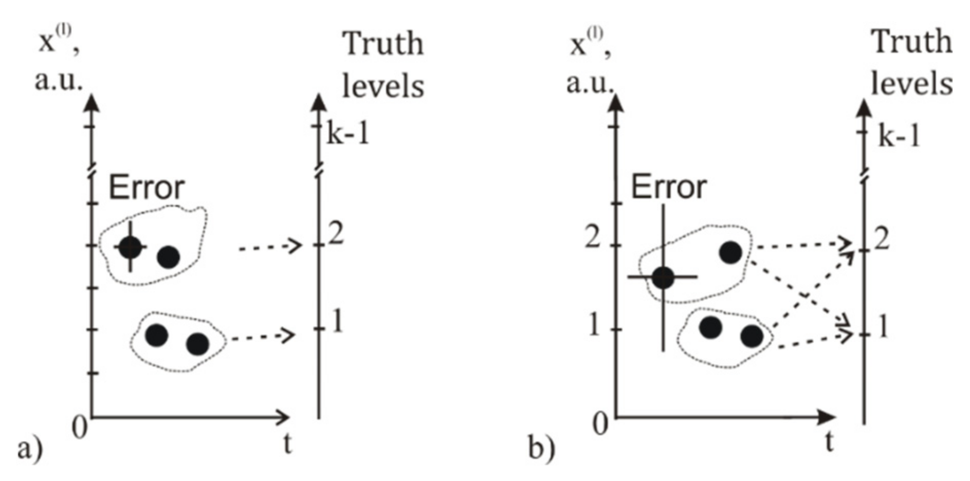
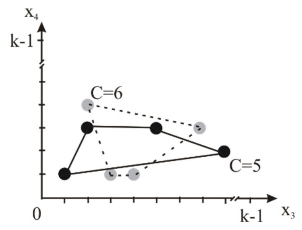
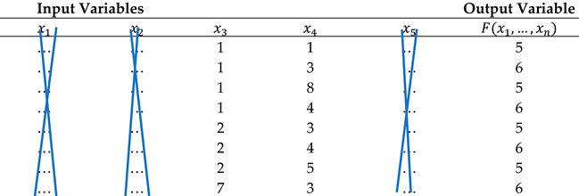
However, the use of correlated variables has some restrictions disclosed by Figure 4 for the correlated space variable, x l . The excessive number of chosen correlated input variables, x l , will finally lead to the situation, when the resulting measurements and the statistical error will achieve the given difference between two neighbor truth levels. Then, according to the theory of physics measurements [81], both truth levels are possible within the given confidence interval, and the AGA model then should add two new product terms, C X i l a , b , with logic constants, C , equal to 1 and 2. This contradicts the principal of AGA modeling of control systems that needs bijective mapping of physical and logic values for forward and reverse interpretation of data. Such ambiguity can lead to errors and needs to shorten the excessive number of correlated variables in case (b); this restriction should be taken into account at least for space coordinates, time, and laser-beam intensity. AGA calculus [70] has not embedded tools to check such data, and the designer should do this himself.

2.5. AGA-Based Versions of the Linked List Scheme for Logic Data Protection

The AGA-based logic version of LL was proposed in References [68,69], intended for agents using MVL and the heterogeneous architecture of the agent. Both versions of AGA-based LL [68,69] were oriented at such practical tasks as follows:
  • Approval of requested numbers of licenses and permissions,
  • Following restrictions declared for cargo parameters and route passing,
  • Monitoring of visits only to legal zones of the geographical map,
  • Loading/uploading at legal terminals,
  • Compliance with the standards of ecology and transport.
Taken together, robotic requests and replies are called entries, which are to be mixed parts of logic notations in LL. The formal structure of AGA-based LL can be given [68,69] by the logic function
  h ( m , s ) = F l l m , t , e m ,   e m s , h m , h m s
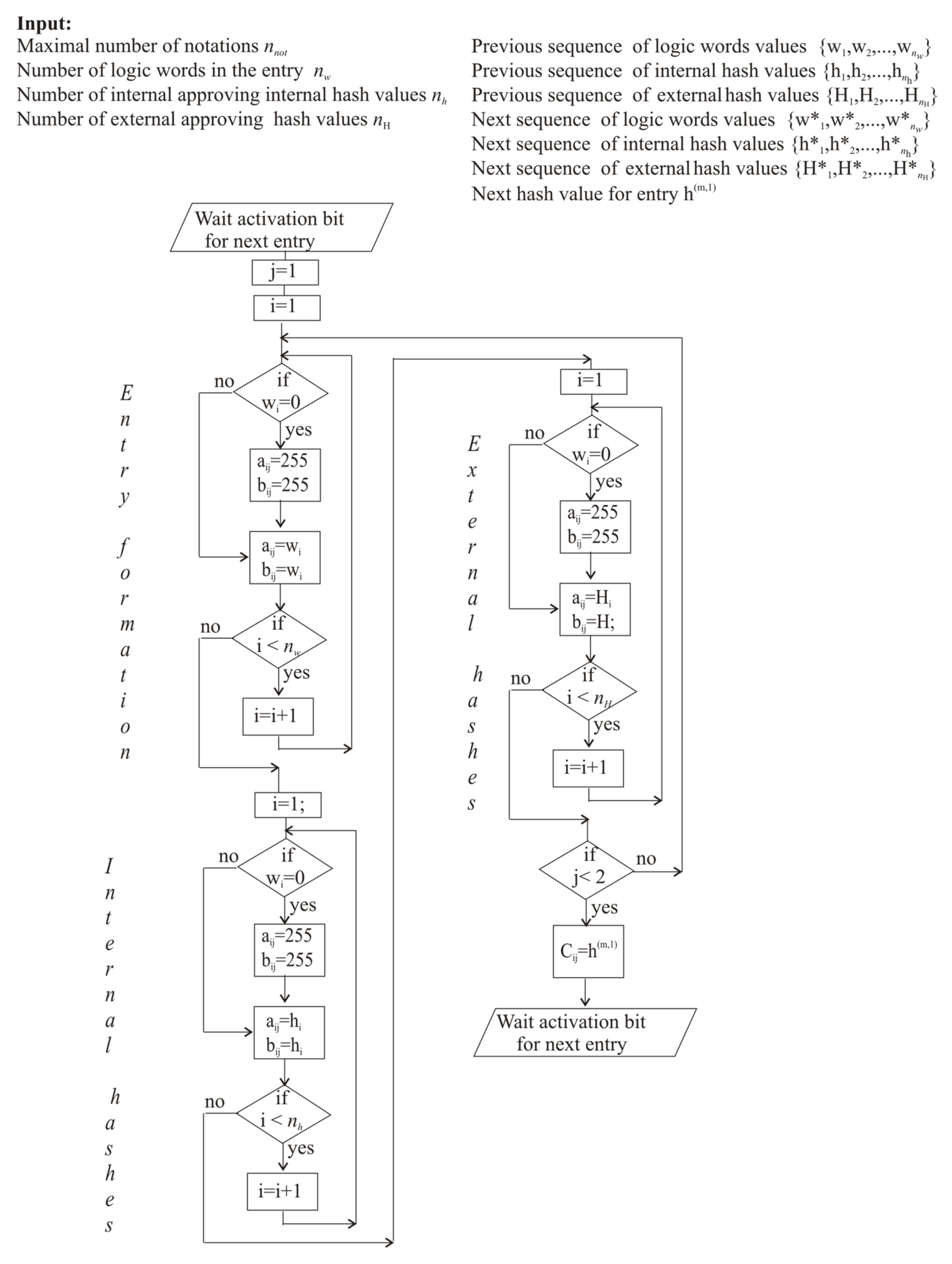
where variables correspond to basic definitions given in Section 2.1 and Section 2.3. Here, the number, m, and the time stamp, t, describe registration parameters of the written next notation; and vectors em, ems describe the last and the previous entries in it. Vectors hm, hms are the approving hash values assigned by verifying network nodes. Entries shift parameter s, which typically can be taken as 1; thus, the LL scheme typically mixes the previous and next entries. The LL model [69] corresponds to the AGA truth table, where the content of the newcomer entry is written as em = (e1,m,…,en,m), the previous entry is em−1 = (e1,m−1,……,en,m) and approving sets of quasi-random hash values are hm= (h1,m,…,hQ,m) and hm−1 = (h1,m−1,…,hQ,m−1) Q is the number of external participants, approving data written to LL. AGA logic expression, Eq. (5), for LL has the structure h ( o u t ) = p.t.1 +,…+ p.t. m, where “+” is the operator Max. The last entry written to Eq. (5) can be represented as a logic product term:
p . t . m = h m m , 1 X m m , m X t t m , t m X e , 1 , m e 1 , m , e 1 , m X e , 1 , p e p , m , e p , m X h , 1 , m h 1 , m , h 1 , m X h , Q , m h Q , m , h Q , m X e , 1 , m 1 e 1 , m 1 , e 1 , m 1 X e , p , m 1 e p , m 1 , e p , m 1 X h , 1 , p e 1 , m 1 , e 1 , m 1 X h , Q , m 1 e Q , m 1 , e Q , m 1 .
where the symbol ⋆ is the logic operator Min.
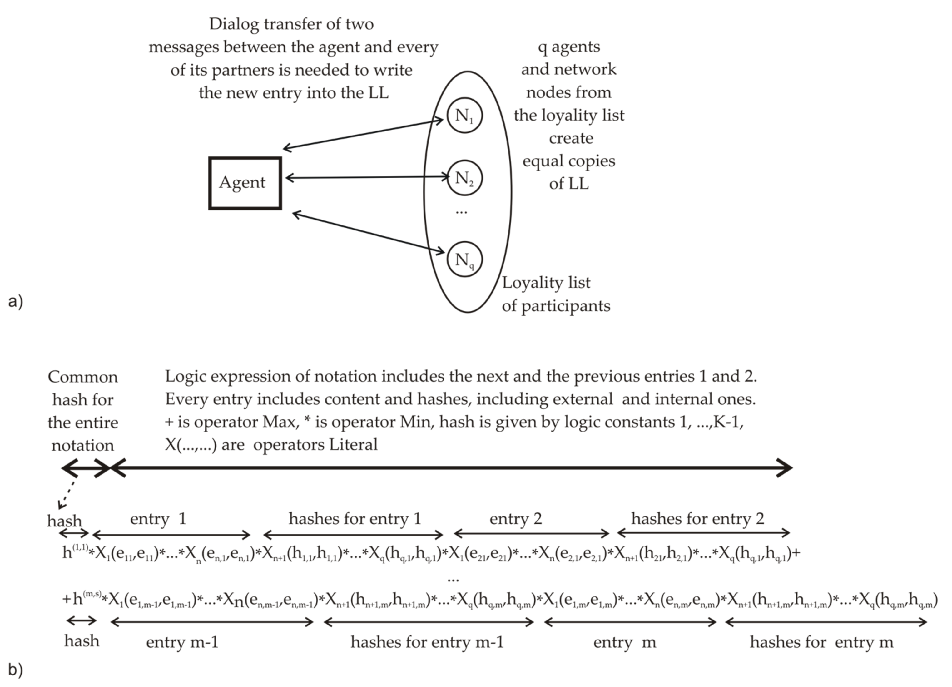
The simplified scheme of AGA-version LL is shown in Figure 5a, where the pre-agreed collective of mutually loyal robots and network nodes is written in the list of participants and creates equal copies of the collectively formed ledger [68,69]. The formal expression structure for AGA-based LL is shown in Figure 5b. The next notation consists of common hash, the previous entry, and the next entry. The entry includes content data and hashes, which can be assigned by external nodes and internal subsystems of the agent. Here, the first logic entry is mixed with the second entry, and, further, the second one is mixed with the third one, etc. Thus, LL “mixes”, by logic operations, random hash values, assigned by external network participants and internal devices with previous and forthcoming entry vectors, e. The MVL version of LL needs to have some store of quasi-random one-time hash values [18] preliminarily generated by a high-quality QRNG [78]. These hash values are being used as access keys in further procedures. Like in the basic blockchain method [54,55,56], useful data written in the entry can be approved collectively by the majority voting of participants, whose result is considered the most reliable one. Certainly, the reliability of such data depends on the number of really involved external participants, and for its small value, it is desirable to introduce additional approving data taken from various internal sources. Due to this reason, the advanced version of AGA-based LL [68] can mix parameters of internal subsystems of the agent with externally assigned hash values.
In order to use AGA-based LL schemes [68,69] in practice, it is necessary to overcome three obstacles. The first of them is to create a control scheme to support the unified protocol, taking into account the real structure of internal modules in various agents. The task here is to “hide” small volumes of critical data, which can later help to detect data errors and modifications. Such resources in agents are considered to be hardly accessible ones, as data procession in them is typically optimized for basic operations, and only limited data volumes can be periodically extracted by allowed polling procedures. Another challenge is to combine automatic and human checks. One more unsolved problem is to prove that no messages were lost, illegally deleted, or added by cheaters. The last opportunity somewhat intersects with the detection of attacks “man-in-the middle” [82], but in contrast to cryptography, now the aim is to prevent data modifications and to imitate the human ability to analyze content in the intermittent dialog.

3. Results: AGA Logic Variables for Scene Description and Dialog Communications

Further, the method is proposed to describe the scene of action and dialogs of agents within AGA, using the large number of truth levels, K     256 [18,68,69], and the ordered structure of coded vocabularies, containing selected basic terminology. Partially, it dates back to ontology methods reviewed in [8].

3.1. Representation of the Scene of Action by Natural Language, Numerical Codes, and Truth Levels

According to Section 1.3, we consider the agent and its MAS within a scene of action (see Figure 2) containing various partner and rival participants. Necessary definitions are given in Table 2. It considers the set (or the total vocabulary), V L , of all different robotic terms, given by words or their collocations, selected by knowledge experts. These vocabularies should describe all input and output variables used in model functions.
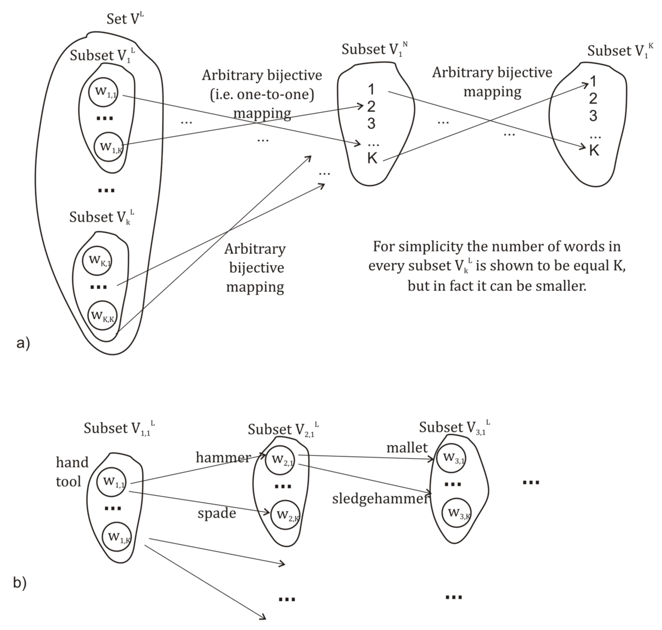
One should note that the coded word may mean the action, tool, equation, and subroutine. Vocabulary can be preliminary selected by library services and processed by experts [83]; here, we omit possible problems surrounding the translation from one language to another one. The selected collection of necessary terms, V L , is to be subdivided into subsets, V v L , describing robotic tasks, actions, and tools by various word classes (noun, verb, adjective, cardinal numbers, etc.). Then, one obtains the representation of all of these terms by unique natural-number code, written in vocabularies, V v N . This intermediate coding is necessary for convenient grouping of terms and verification procedures. Further one should map natural-number codes onto the discrete scale of truth levels, K , defined in AGA, and the corresponding structure of mapping is shown in Figure 6.
The specific situation of mapping on V v K in Figure 6a is that we can randomly assign truth levels to words or conveniently choose them for the classification of objects [75]. As the simplification (and shortening) of AGA expressions is based on the consensus method of minimization [70], it can regroup logic product terms according to assigned logic constants. A substantial feature of the used subsets, V v L ,   V v N ,   V v K , is that the number of elements in them is less or equal to K , and unused vacancies in subsets are to receive zero values. Mappings V L V N and   V N V K are bijective: each element of a subset maps to only one of elements in another subset, providing simple forward and backward translation by transcoding tables. The chain-mapping scheme is disclosed by Figure 6b and responds to sequential clarification of content by the finite chain of conjugated vocabularies, V 1 , m L V 2 , m L V 3 , m L V K , m L , where V 1 , m L is a root vocabulary. Such a method is used to provide the unified protocol for all robots, exploiting simple and advanced hardware platforms, where the first part of the message can contain coded words defined closer to root vocabularies. Then, the overall actuality of information can be quickly estimated by all agents, even those capable of interpreting only part of the message. In such a scheme, agents can undertake actual action immediately, before the transfer of all details.
The formation of content root vocabulary, V L , is given in Table 3, which describes words of natural language. Every term (or word combination) of natural language is included in some vocabulary. Every vocabulary, V v , m L , contains up to K different words, w v , m . L . Numbers N = 1 ÷ M refer to root vocabularies. Values N from K + 1 up to 2 K refer to the second one in the chain mapping of vocabularies. For the sake of brevity, only two chain vocabularies, V v , 2 K , are shown in Table 3.
The first field in Table 3 is the initiation (or welcome) word of dialog, also indicating the type of communication format for messages and the number of parts in the phrase, which may differ for various sectors of robotics.
Every agent, tool, and identified object in the scene of action can have only one name. The name of addressers and senders may include several bytes or chain elements, defined by the matrix, V v , m K , taken with two parameters,   v , m     K . For the sake of simplicity, we avoid using the third index for the description of the number of a word in the vocabulary.
AGA modeling of the scene of action is based on three equivalent representations of vocabularies, V v , m L V v , m N   V v , m K   , as shown in Table 4. Such parallel use of natural language description, natural-number code, and truth-level code is convenient for human experts, as it corresponds to the situation, when one first explains orally the work of the designed robotic system and, after this, turns to number codes and AGA models.
Correlated variables can be written (see Table 4) as a sequence of w i , g , k K , sequentially raising the precision of space coordinates, but following the restriction given in Section 2.4.
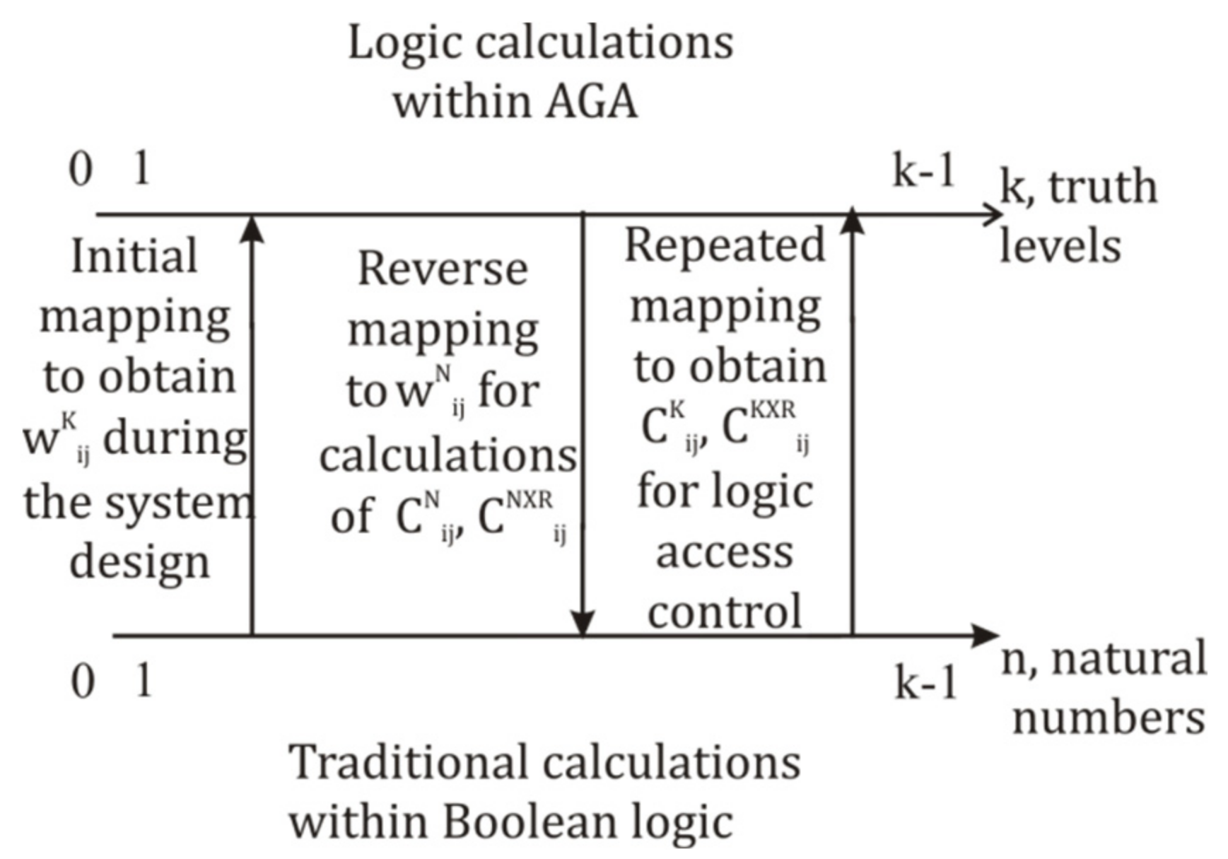
The scheme of logic transformations between natural-numbers code and truth levels ones is given in Figure 7, which shows the initial mapping of w i , j N   data onto the logic representation scale w i , j K . Also, the reverse mapping to natural numbers is given, as arithmetic calculations of check coefficients are to use Boolean logic. For convenient procession, the maximal logic value, K 1 , and its natural numbers equivalent are reserved for possible minimization procedures in AGA [75]. By default, zero value indicates the unused word in a vocabulary, also providing zero in corresponding product terms. Check coefficients, C i , j N ,   C i , j K , C i , j N X R ,   C i , j K X R , are to be calculated within the mapping of AGA to the natural-number scale (see Section 3.3).
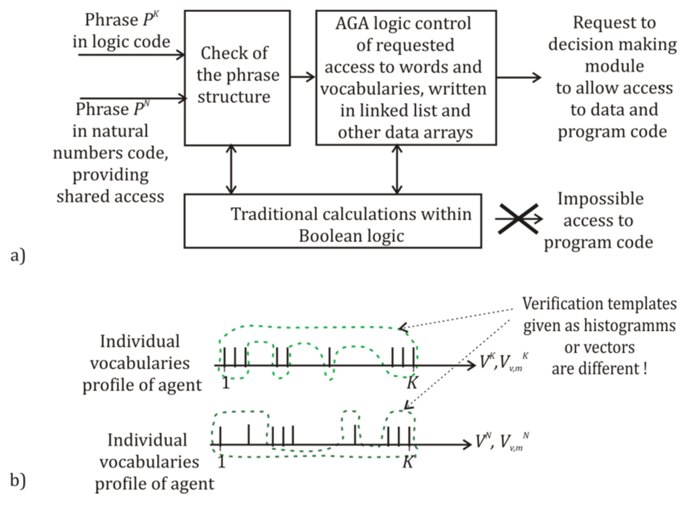
Verification procedures, shown in Figure 8a, can involve two data input channels, using truth-level codes and natural-number ones. One can process and compare data coded in both variants. That gives the possibility to separately compare the final and intermediate results and to detect errors or illegal modifications of data. For example, the final results in both representations should be the same or close if approximate estimations were used. Also, three equivalent representations are considered as the binding tool for the heterogeneous logic architecture of agent [75], which supposes parallel calculations in various logic models.
At the same time, natural-number code and mapped AGA truth levels have different number profiles for comparison. Figure 8b shows the principle of brief verification procedure for used vocabularies in the agent. Data representation by the histogram shown in Figure 8b is convenient for human checks. Within the proposed scheme of vocabularies, known types of activity and coded tasks’ execution should lead to a preliminary known set of vocabularies, describing the task of the agent. Independent checks may be held in both vocabularies V v , m N and V v , m L .
As AGA truth-level representation w v , m K is compatible with the secret data coding scheme [18] and the scheme for distant comparison of data without their disclosing [68,69], it is preferable to use it for the control of data access in agents. Natural-number codes, w v , m N , are better to describe common access content and less confidential data. A full check of the agent will need a comparison of all words, w v , m K and w v , m N , in used matrixes, V v , m K   and V v , m N . However, all such procedures need one more critical component.

3.2. Communication Phrase

There exist formal theories of language construction like those considered in [84], although modern natural language procession systems typically use neural networks and Chat GPT v.3.5 [65]. However, earlier, the simplest AGA-based scheme of the communication protocol was proposed in [26] for the transfer of confidential instructions via the wireless laser data line   λ = 0.63 μm, with pulse-width modulation. This scheme has used the fixed position of several specialized vocabularies in the phrase W and was intended for 8-bit microcontrollers platforms. The small number of internal memory registers in them has limited the transfer of short phrases given by the format {Sender of message–Receiver of message–What to do–Where to do–When to do–Commentary for next phrase}, coded by 8-bit numbers. This earlier version of protocol corresponds to the shortened sampling taken from Table 3 for the particular set of vocabularies:
{ V 2 L ( Sender   of   message ) V 3 L ( Addresser   of   message )   V 4 L ( Task ) V 6 L ( Place   of   action V 13 L T i m e   o f   a c t i o n V 1 L F o r m a t   o f   n e x t   m e s s a g e }
However, now the task is to propose the flexible and unified 8-16-32-… phrase format, adaptable to various tasks and the large number of vocabularies. Also, such a format should help to find correct parts of phrase and to determine the lost ones.
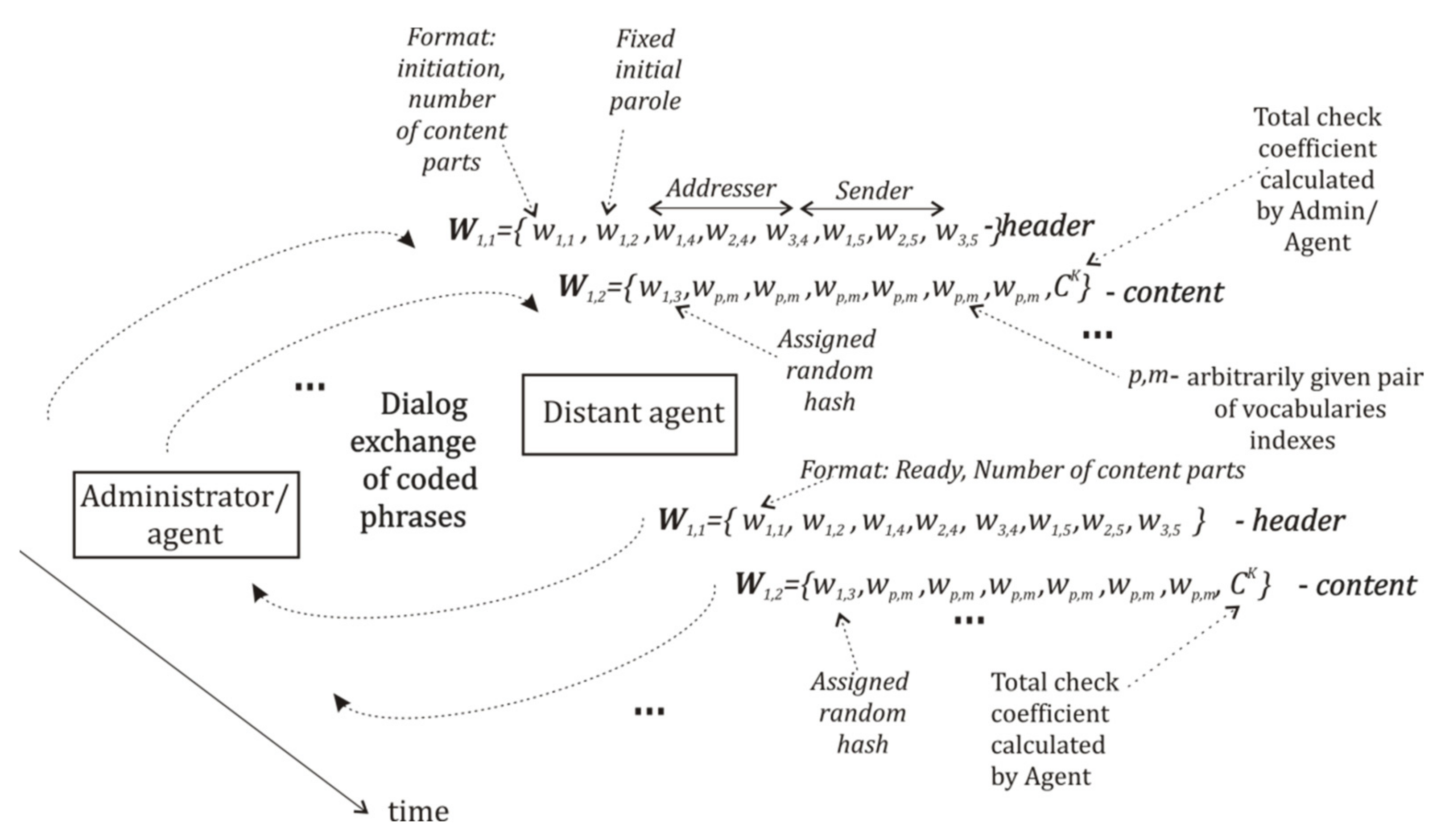
The necessary structure of the phrase vector W K , describing the robotic message, is given in Table 5. Every phrase is a fragmented one and contains the addressing header and content parts. Their length is 8 bytes, a value that is accessible for cheap 8-bit platforms. The overall length of W K principally can be enlarged up to K parts, but it is supposed to be typically limited by 2–8 ones. Components of vector W K are the elements of various vocabularies given in Table 3 and Table 4. Principally, alternative representations by words w v , m N also can be used in phrases, but in this paper, we do not use them. The parts of phrase shown in Table 5 can be transmitted separately and afterward may be assembled into holistic phrases with the help of hash values and total check coefficients. That excludes the possible problem of time delays for multi-channel data aggregation.
The header part includes obligatory fields, “format”, “fixed parole”, “addresser”, and “sender”, with the fixed position in the phrase for the quick and simple procession. Priority of position of the root and other vocabularies in the phrase is given by the field “format”. The value     w 1,1 K = Hi ” may be given by several various numbers, initiating the new dialog and also indicating the number of content parts. The field “fixed parole” is intended for the initial access of preliminary allowed agents, and it includes words taken from the vocabulary V 1,2 K that contain fixed passwords for initial contact only. Further communication modules in sender and addresser should assign quasi-random hashes to content parts of the phrase. Every content part also includes the obligatory field “hash”, describing assigned one-time quasi-random hashes necessary for correct integration of transferred parts into the holistic phrase. This field is used to store random keys, taken from the storage, containing data received from an external QRNG [69] or a random oracle scheme [61]. The fields “arbitrary code word,   w v , m ” in the content parts of the phrase are to be filled in by arbitrarily chosen words, forming some sampling, K , of logic variables, where K K . The maximal number of content parts, j , in the phrase is determined by the expression
j = N   u s e d   v o c a b .   i n   p h r a s e N u s e d   i n   h e a d e r / N f r e e   f i e l d s   i n   c o n t .   p a r t = ( K × M 4 ) / N f r e e   f i e l d s   i n   c o n t .   p a r t
The format of messages shown in the Table 5 certainly can be further adapted for a specific knowledge domain, a large number of participants, and large space and time bands of work. For example, for extraordinary situations like a fire, any robot should have a reserved code word in the field “format” for the activation of chain vocabularies, describing phrases like {Fire service–Fire department q–Fire robot qq–….} and {City q–Municipal district qq–Street qqq–…}. But for routine tasks such as long chains of vocabularies, it can be excessive.
Total check coefficients,   C K and C N , shown in Table 5, need special commentary, as they suppose arithmetic summation of word codes for message integrity verification. Such verification procedures for a noisy data line can determine if some parts of the phrase were modified, added, or lost due to noise or intruders. This method assumes the summations of codes for all used indexes, v and m, and parts of phrase. As the summation is not initially defined in AGA [70], and one cannot directly use Boolean calculations for the set of truth-level data; words codes should be preliminary mapped onto the scale of natural numbers, N , before traditional arithmetic calculations. The results of the calculations should coincide for sums obtained by the addresser and sender. For 8-bit microcontrollers [85,86] with embedded arithmetic procedures, this check unavoidably uses the summation with case overflow, which provides the independence of the verification parameter from the number of actually used words and transmitted parts of the phrase. Besides this, in such schemes, the well-known binary operation XOR, used in [85], may be also applied for the detection of errors in parts of the phrase. In order to use such verification schemes, one should make several definitions.
Definition 1.
Total check coefficient,  C i K of mapped truth levels is given for a phrase,  W i , written in AGA logic codes and is the arithmetic summation,  C i K =   v K w v K , carried out within Boolean logic for truth values of all words,  w v K , used in the phrase,   W i , and given by arbitrary sampling of vocabularies  V K ,   K   K .  AGA truth levels before summation are mapped onto the linear scale of natural numbers, N.
Application of the def. (3.1) is supposed to be convenient both for independent human checks and for automatic comparison with template data.
Another convenient coefficient for checks is given by Definition 2.
Definition 2.
Total check coefficient,   C i N / K , of arithmetic summation of natural-numbers codes is given for a phrase,   W i , written in mixed natural-number and truth-levels code and is the arithmetic summation    C i N / K =   v N w v N / K , carried out for natural-number codes and mappings of truth-level codes of words   w v N    or  w v K , used in the phrase  W i  and taken from the sampling set of vocabularies  V N  and  V K ,  N , K     N .
The coefficient C i N / K is necessary for human or automatic checks within the heterogeneous logic architecture of agent, where one can independently visualize natural-number codes and evaluate the integrity of the dialog data exchange by the summation of all values, w v N , in the phrase.
One more useful tool for the logic verification in agent is the well-known Boolean logic operation XOR, used for the set of words in the phrase W i , represented by truth levels or natural numbers. Its destination is to make digital “fingerprints” for phrases and their parts. XOR operation can help to compare identity and to hide real codes used in data channels without secret coding.
Definition 3.
Total coefficient  C i X R K  of check XOR binary logic operation taken for mapped truth levels is the set of Boolean XOR operations,  C i X R K =   w 1 K ^ w K K ^    carried out in the phrase   W i  for binary representation of AGA truth levels of words,  w v K ^ ,  mapped onto the linear scale of natural numbers N.
Definition 4.
Total coefficient  C i X R N  of check XOR binary logic operation is the set of Boolean XOR operations,  C i X R N =   w 1 N w K N  carried out in the phrase    W i  for binary representation of natural-number codes of words,  w v K .
One should note that coefficients Def. 1 ÷ 4 also can be easily used in phrases W i ,   transmitted by parts, as shown in Table 4. “Sewing” or ordering of parts of the phrase W i in the addresser agent supposes the check of coefficients Def. 1 ÷ 4 as for whole phrases, as for their separate parts. The only necessary complication here is to insert separately calculated coefficients in the end of every phrase part (see Table 6) and to fill in the total sum for all parts of the phrase, including the header. The specifics of coefficients Def. 3 ÷ 4 is that they are intended for more confidential data or for work in the tense media, when the increased level of caution is to be activated in the MAS.
The detection of lost and mixed content parts during the transfer of phrases in dialog mode can be based on the check for assigned one-time hash values and the comparison of data, obtained by the summation of coefficients, C i . j K . An example of such an algorithm is given in Section 3.3. Besides this, for vocabularies V v , m N , where   v 1 , , K ,   m 1 , , M ,   M K , one can apply coefficients   C N   and   C N X R , taken in natural numbers representation.

3.3. Communication Module and the Dialog Protocol

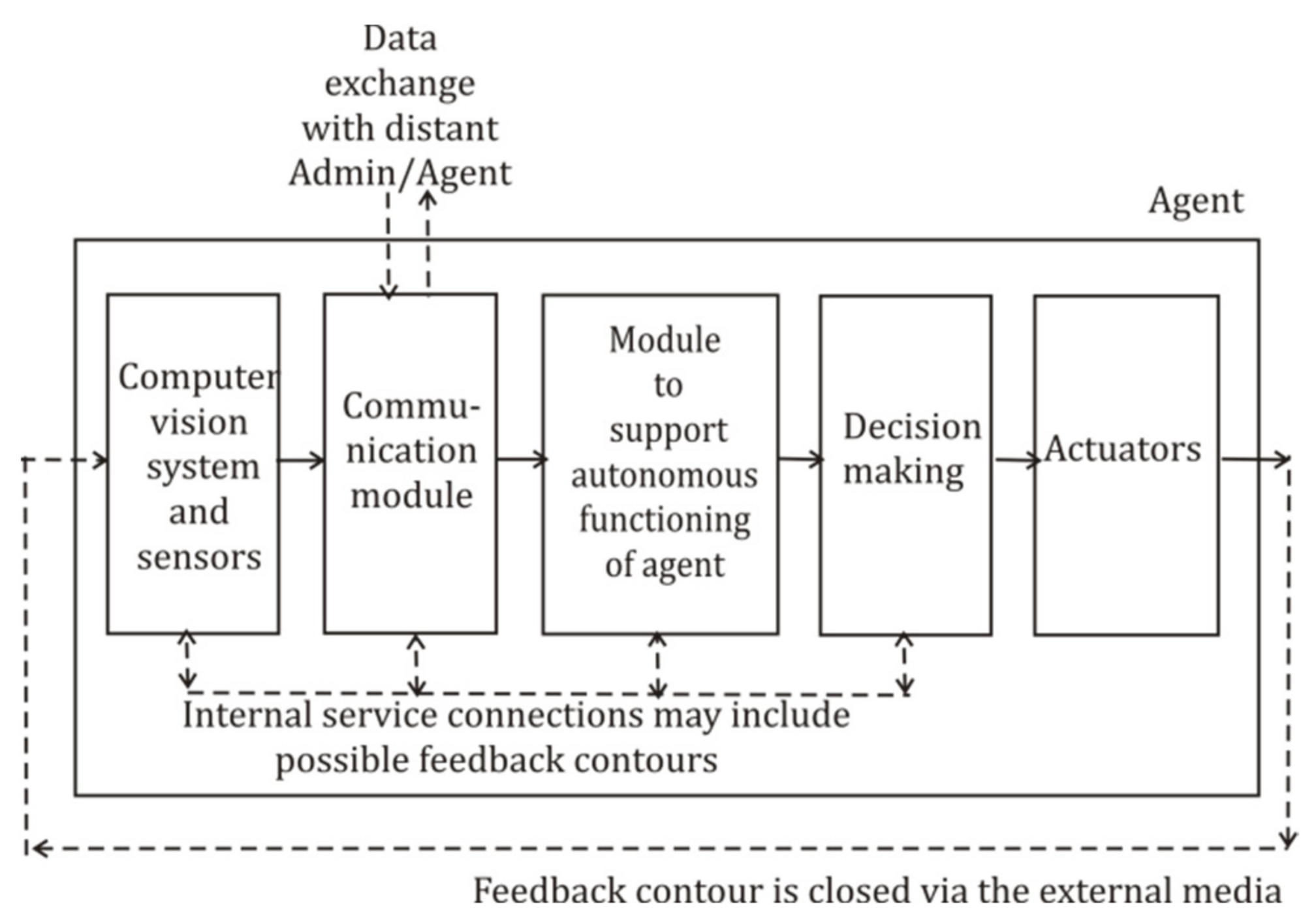
Procession of dialog messages is considered further only within the specialized communication module, but for the correct design of verification procedures, it is necessary to briefly discuss its interaction with other agents’ components. The very simplified interpretation scheme of agent and its basic work cycle is shown in Figure 9; however, its internal modules can use additional feedback contours and data lines.
Any realistic autonomous mobile robot should include the following:
  • Sensors and computer vision system, which are to detect objects and dangers, providing the agent’s reactivity to the external world and space positioning;
  • Module for the procession of messages, coming from radiofrequency, acoustic, and optics data lines, complemented by devices for secret coding and data verification;
  • Homeostasis supporting system [87], providing autonomous operation of devices for energy supply, time clocking, sensors operability control, and space positioning;
  • Modules for decision making and work planning;
  • Set of actuators.
Principally, one of main properties of agent is to follow the principle of the so-called homeostasis in biological systems [87] and to support autonomous work of a robot by self-sustaining of appropriate bands of “vital” parameters, like alive systems support concentration of oxygen and glucose in blood using the cyclic principle of work and control contours with feedback. Using internal subsystems, the agent executes received tasks and instructions [86], somehow changing the external media. The agent sequentially monitors these changes via its sensors and repeats the work cycle, thus realizing closed contours of control with the feedback obtained via the external media. Such cycles can involve time bands varying at least from nanoseconds up to months, and they need to use correlated time variables. That is why the universal communication module of agent and verification procedures should model the detailed structure of parameters, and it cannot be limited by several verification templates.
The message-receiving agent is to take into account instructions transferred by the administrator and requests received from other agents, which may quickly change states of homeostasis contours. Only after this is the agent supposed to activate decision-making procedures, which may cause a series of actions and need various run times. As the embedded modules of the agent somehow suppose an optimized mode of work, the realistic way is to run verification procedure after the completing of the next work cycle [85,86].
If some agent receives the initiating signal in a new phrase, the dialog scheme of two agents can include a vast spectrum of procedures and AI algorithms as follows:
  • To check the received initial parole in the list of fixed and additionally generated ones;
  • To extract potentially danger data to be immediately sent to homeostasis module,
  • To check the presence of the declared sender name and its authority in the AGA function, describing allowed classes of actions for the contacting agent,
  • To verify the presence of all declared content parts in the received phrase;
  • To compare the requested by external agent set of vocabularies with the allowed one;
  • Either to begin the new dialog or to continue the already opened one; if necessary, to send denial reply;
  • To send content of the received phrase to the decision-maker and to wait for its reply;
  • To work out the reply phrase and to assign a one-time random hash value to it, using the reserve list of hash values, preliminarily filled in by quasi-random numbers;
  • To analyze the reason for errors in the dialog and to choose adequate actions.
The proposed further scheme of dialog communications, combining AGA control of vocabularies and the binary calculation of total check coefficients, is based on Table 3 and Table 5 and is given in Figure 10. All phrases, Wij, are subdivided into initiating dialog requests and reply to them.
According to Table 5, all phrases in the request and reply messages include the header with several obligatory fields and content parts. Indexed values, Wij, define some sampling of words, which are chosen from the corresponding set of vocabularies by the communication module and the decision-making module. The external communication module of administrator and agents adds hash value into the phrase, which can be either the fixed initial access password, w1,2, or the assigned one-time quasi-random hash value, w1,3 = hi,j. In Figure 10, it is supposed that the communication session is a new one, and sender of the phrase initiates the dialog, so that the first field “format” in the header of the phrase should contain the initiation word,   w 1 K = “Hi”. It further activates the input of initial access parole,   w 1,2 K , written in the vocabulary   V 1,2 K . This set (or list) of fixed passwords is intended only for the initiation of new sessions, as during the already opened communication session, interacting agents should add one-time hash values taken from the preliminary generated list, L h a s h . Other components of the header of the phrase W 11 = {   w 1,1 K ,   w 1,2 K , …. } are the triples, ( w 1,4 K , w 2,4 K , w 3,4 K ) and ( w 1,5 K , w 2,5 K , w 3,5 K ) , describing all given addressers and senders. Such an 8-bit triple can support 16,777,216 agents.
The phrase procession scheme shown in Figure 10 corresponds to Algorithm 1. It describes the overall scheme of formal checks of initiating words, passwords, check coefficients, search of the header and content parts, and the waiting of reply in the dialog mode.
Algorithm 1. Phrase procession for dialogs administrator–agent and agent–agent from the same MAS. Total check coefficients, C K / N o r   C K X R , are calculated by arithmetic summation or binary XOR operations performed for mapped truth levels. Phrase can initiate the new dialog or continue the already opened one.
Input: K Number of truth levels in AGA;
V v , m K Vocabularies in truth levels representation;
( w 1,4 K , w 2,4 K , w 3,4 K ) Addresser code, given by the triple of coded truth levels in chain vocabularies;
( w 1,5 K , w 2,5 K , w 3,5 K ) Sender codes triple;
( p , q , w p , q K ) ,   , ( r , s , w r , s K ) Set of triples, representing content data given by decision-maker for transfer to addresser; p , , q  and    r , , s arbitrarily given enlarging values, p ≤ r, q ≤ s;
w 1,1 K Welcome code {“Hi”} to begin new session;
  w 1,2 K Fixed parole for initial access to addresser;
  w 1,3 K Assigned hash value;
L a l List of allowed contacters;
L s List of addressers with opened sessions;
L h a s h List of accumulated quasi-random keys, h i j L H A S H , taken from QRNG;
NSubjectOperationCommentary
1Sender
( w 1,5 K , w 2,5 K , w 3,5 K );
Checks ( w 1,4 K , w 2,4 K , w 3,4 K ) L a l ,
and if yes, go to step 2;
otherwise, it goes to the procedure for unknown contacters
; if list L a l of allowed contacts contains addresser’s name triple:
2 Assigns i = 1, for empty phrase header template
W i , j = { , , , , , , , } ;
; begin new phrase and header
3 Assigns j = 1; number of content part
4 Assigns format w 1,1 K = " H i to phrase header part
W i , j = { w 1,1 K , , , , , , , } ;
; initiation of dialog
5 Assigns fixed parole w 1,2 K of Addresser ( w 1,4 K , w 2,4 K , w 3,4 K )   to phrase header
W i , j = { w 1,1 K , w 1,2 K , , , , } ;
; takes fixed w 1,2 K   from V 1,2 K
6 Assigns addresser’s triple name ( w 1,4 K , w 2,4 K , w 3,4 K ) to the header
W i , j = { w 1,1 K , w 1,2 K ,   w 1,3 K , w 2,3 K , w 3,3 K , , , } ;
; insert triple V 1,3 K , V 2,3 K , V 3,3 K
7 Assigns own sender’s triple name ( w 1,5 K , w 2,5 K , w 3,5 K ) to the header
W i , j = { w 1,1 K , w 1,2 K ,   w 1,4 K , w 2,4 K , w 3,4 K , w 1,5 K , w 2,5 K , w 3,5 K } ;
; insert triple V 1,4 K , V 2,4 K , V 3,4 K
8 Maps truth levels onto natural numbers scale and calculates total check coefficient, C i . j K / N , for the header
C 1,1 K / N = m = 1 2 w 1 , m K + v = 1 3 m = 3 4 w v , m K / N ;
9 Calculates number of content parts:   N C   ( r   x   s p   x   q ) / 6 ;   N C N ,     p , q , r ,   s   are taken from the received content data sequence { w p , q K ,   , w r , s K } ;; number of content parts is determined by 6 free fields in any of them
10 Assigns v = p, m = q; set counters of chain vocabularies
11 Assigns j = N C ; begin content parts and set their counter
12 Assigns g = 6; counter of free fields in a content part
13 Writes next hash w 1,3 K from the list L h a s h to the first field of phrase content part W i , j = w 1,3 K , , , , , , , , ; ; begin new content part
14 Goes to step 18; next content part
15 Checks if m = s ,     and if yes, it goes to step 23;
otherwise, it goes to step 18.
16 Checks if v = r ,     and if yes, it goes to step 26;
otherwise, it goes to step 18.
;end of phrase formation
17 Checks if j = 0 ,   and if yes, it goes to step 12;
otherwise, it goes to step 25.
18 Write w p , q K into the next vacancy in the content part, W i , j + 1 = w 1,3 K , w p , q K , w p + 1 , q K , w p + 2 , q K , , , , ,
19 g = g – 1; check for free fields
20 Checks if g = 0 , and if yes, it goes to step 25;
otherwise, it goes to step 21.
; m + 1
21 m = m + 1
22 Goes to step 15
23 v = v + 1; process next v
24 Goes to step 16
25 Maps truth levels onto the natural numbers scale and calculates total coefficient, C i . 2 K , of the content part
C i . j K / N = h i j a d + v = p q m = r s w v , m K / N c o n t e n t   p a r t
26 Calculates total summation
C t o t a l K / N = C 1,1 K + i = 2 N c j = 1 N c C i , j K / N
27 Writes C t o t a l K / N   into the current content part of phrase
W i , j = w 1,3 K , w v , m K , w v , m K , w v , m K , w v , m K , w v , m K , w v , m K ,   C t o t a l K / N
28 Sends the header W i , j   and content parts W i , j + 1 , W i , j + 2 , to addresser
29 i = i + 1; counter of phrases for continued dialog
30 Waits reply from addresser
31Addresser
  ( w 1,4 , K w 2,4 K , w 3,4 K )
Writes message parts in the buffer:
W i , j = { w 1,1 K , w 1,2 K ,   w 1,4 K , w 2,4 K , w 3,4 K , w 1,5 K , w 2,5 K , w 3,5 K } ;
W i , j + 1 = w 1,3 K , w v , m K , w v , m K , w v , m K , w v , m K , w v , m K , w v , m K ,   C t o t a l K / N
; indexes v , m indicate arbitrarily given words
32 Reads word w 1,1 K in the Format field of the phrase header
W i , j = { w 1,1 K , w 1,2 K ,   w 1,4 K , w 2,4 K , w 3,4 K , w 1,5 K , w 2,5 K , w 3,5 K } ;
33 Assigns the number of content part j =   N C
34 Checks if list L s   of opened sessions contains addresser’s name
( w 1,4 K , w 2,4 K , w 3,4 K ) declared in the header W i , j :
Checks if w 1,4 K , w 2,4 K , w 3,4 K L s , and if yes, it goes to step 38;
otherwise, it goes to step 35.
35 Checks if list L a l of allowed contacters contains addresser’s name
( w 1,4 K , w 2,4 K , w 3,4 K ):
Checks if w 1,4 K , w 2,4 K , w 3,4 K L a l , and if yes, it goes to step 37;
otherwise, it goes to step 36.
36 Send denial of service message
37 Maps truth levels onto natural-number scale and calculate total coefficient for the header C i , 1 * K = m = 1 2 w 1 , m K + v = 1 3 m = 3 4 w v , m K ;; check received external coefficients
38 Maps truth levels onto natural-number scale and calculate total coefficient for content parts
C t o t a l * K / N = C i , 1 * K + i N c j = 1 N c C i , j * K / N
39 Compares the received and the declared values:
Checks if C t o t a l * K = C t o t a l K ; if yes, goes to step 40.
Otherwise, it goes to step 36.
40 Sends received phrase content   ( p , q , w p , q K ) ,   , ( r , s , w r , s K ) to decision-maker; excluding hashes and check coefficients
41 Waits for reply from decision-maker
42 Receives reply ( p , q , w p , q K ) ,   , ( r , s , w r , s K )   from decision-maker; for the sake of simplicity, indexes are the same as in step 32
43 Assigns next quasi-random hash from the list L h a s h to w 1,2 K = h i j
44 Assigns i = 1 for empty phrase template
W i , j = { , , , , , , , }
; form reply phrase
45 Assigns j = 1
46 Assigns Format w 1,1 K = “Received” to phrase header
W i , j = { w 1,1 K , , , , , , , }
; format differs from request
47 Assigns fixed parole, w 1,2 K , of sender to phrase header
W i , j = { w 1,1 K , w 1,2 K , , , , }
; takes fixed w 1,2 K   from V 1,2 K
48 Assigns sender’s triple ( w 1,5 K , w 2,5 K , w 3,5 K )   to phrase header part
W i , j = { w 1,1 K , w 1,2 K ,   w 1,5 K , w 2,5 K , w 3,5 K , , , }
49 Assigns own code ( w 1,4 K , w 2,4 K , w 3,4 K ) to phrase header part
W i , j = { w 1,1 K , h i j a d ,   w 1,5 K , w 2,5 K , w 3,5 K , w 1,4 K , w 2,4 K , w 3,4 K } ;
50 Assigns j = j + 1
51 Maps truth levels onto natural number scale and calculates total check coefficient, C i . j K / N , for the header,
C 1,1 K / N = m = 1 2 w 1 , m K + v = 1 3 m = 3 4 w v , m K / N ;
52 Calculates number of content parts:   N C   ( r   x   s p   x   q ) / 6 ;   N C N ,     p , q , r ,   s   are taken from the received content data sequence { w p , q K ,   , w r , s K } ;; number of content parts is determined by 6 free fields in a content part
53 Assigns v = p, m = q; set counters of chain vocabularies
54 Assigns j = N C ; begin content parts and set their counter
55 Assigns g = 6; counter of free fields in a content part
56 Writes next hash w 1,3 K from the list L h a s h to the first field of phrase content part W i , j + 1 = w 1,3 K , , , , , , , , ; ; begin new content part
57 Goes to step 61; begin next content part
58 Checks if m = s , and if yes, it goes to step 66.
    Otherwise, it goes to step 61.
; check counter
59 Checks if v = r , and if yes, it goes to step 60.
    Otherwise, goes to step 61.
; end of phrase formation
60 Checks if j = 0 , and if yes, it goes to step 55.
Otherwise, it goes to step 68.
; check counter
61 Writes set of w v , m K into the next vacancy in the content part W i , j = w 1,3 K , w v , m K , , , , ,
62 Assigns g = g − 1; free fields control
63 Checks if   g = 0 ,   and if yes, it goes to step 68;
Otherwise, it goes to step 64.
; m + 1
64 Assigns m = m + 1
65 Goes to step 58
66 Assigns v = v + 1; process next v
67 Goes to step 59
68 Maps truth levels onto natural numbers scale and calculate total coefficient C i . 2 K of content part
C i . j K / N = h i j a d + v = p q m = r s w v , m K / N c o n t e n t   p a r t
69 Calculate total summation
C t o t a l K / N = C 1,1 K + i N c j = 1 N c C i , j K / N
70 Writes C t o t a l K   into the current content part of phrase
W i , j = w 1,3 K , w v , m K , w v , m K , w v , m K , w v , m K , w v , m K , w v , m K ,   C t o t a l K / N
71 Replies to sender and transfer the header W i , j   and content part   W i , j + 1
72 i = i + 1
73 Waits for the next dialog phrase
Output: →Formation and transfer of the request W 1,1 , W 1,2 to addresser, and procession of reply W 2,1 , W 2,2 to sender, saving total check coefficients C i , j K / N   in memory for the continuation of the dialog.
Besides the correct content part, the receiving buffer of agent potentially can contain, by mistake, some excessive illegally sent parts or ones taken from someone else’s message. Its analysis is based on the simple summation of mapped truth levels and the comparison of total check coefficients, obtained by the addresser and declared by the sender. This simple procedure is given in Algorithm 2, which demonstrates the scheme to find correct content part in the buffer memory, using the actual header part of the phrase.
Algorithm 2. The procedure to find correct content part, corresponding to the given header, based on check coefficients.
Input: {   w 1,1 K ,   w 1,2 K ,   w 1,4 K ,   w 2,4 K , w 3,4 K ,   w 1,5 K ,   w 2,5 K ,   w 3,5 K },
{   w 1,3 K ,   w v , m K ,   w v , m K ,   w v , m K , w v , m K ,   w v , m K ,   w v , m K ,   C N / K },
………..
(up to 30 parts in the buffer)
Header
Content parts
StepProcedureExample from Table 6
1.Find header part of phrase in the buffer memory-
2.Calculate with 8-bit overflow C h e a d e r N / K for the header C N / K = 138 (<255)
3.Find nearest content part-
4.Calculate with 8-bit overflow C c o n t N / K for the content part209 + 196 + 3 + 12 + 6 + 221 + 147 = 794 (overflow: >255) =
= 794 − 3 × 255 = 29;
5.Calculate with 80bit overflow:   C h e a d e r N / K +   C c o n t N / K 138 + 29 = 167 (<255)
6.Compare, if the calculated result is equal to the declared one in the last field of the content part:
C h e a d e r N / K +   C c o n t N / K = C h e a d e r * N / K +   C c o n t * N / K ;
If yes, then write header and content part in the buffer;
otherwise, then find and process next content part.
-
 
167 = 167
yes
Output:→ Correct pair of header–content part of phrase is in the buffer.
Its work is disclosed also by the numerical example given in the Table 6. It represents the header and the content part of the phrase, containing numerical data. This procedure is intended for embedded summation procedures in 8-bit MCS-51microcontrollers used in the platform discussed in Section 6. Firstly, it calculates the summation of check coefficients for the earlier found correct header part, determined by the subroutine CHKPHR in Section 6. The term “correct header” here means adequate addresser and sender codes. The corresponding summation = w v , m for this header and produces the result 138. The procedure further adds data from seven cells in the content part and outputs 794. But due to the overflow mode of the transfer bit, one should subtract 3 × 255. The final result is equal to 167, which coincides with the result, declared in the last cell of the content part. This content part corresponds to the chosen header.
The further procession of the received phrase, Wi,j, should include the check for compatibility of allowed tasks and vocabularies mentioned in the request. The detailed analysis of this vast topic is out of the scope of this paper; only a few remarks are to be given. The aim here is to detect incorrect content messages and to limit the access of robots to currently unallowed topics and knowledge. Thus, we need to design a special AGA function, which, in the general case, should take into account the current state of the scene of action and the dynamics of its development. This procedure needs to additionally estimate such control parameters as, e.g., the level of danger, the trust level, and the level of available resources. Thus, the principle of multi-parametric AGA logic phrase procession is simple enough, but realistic design needs to add many expert data. Some of them are preferable to be written as templates for verification and should be protected from illegal modifications by the adaptation of earlier proposed schemes of AGA-based LL [68,69].

4. Results: Adaptation of LL to Dialog Verification Procedures

The main motive to use namely AGA function for the realization of LL is determined by the possibility to easily generate the single logic function, combining all necessary content data and approving quasi-random hash values. All logic variables in it are clear for checks and do not require any questionable estimations performed by extraneous persons. In combination with microassembler programming, which traditionally provides more reliable procedures for classic and quantum cryptography, AGA procedures can be analyzed and checked directly by the user.
Earlier proposed versions of AGA-based LL [68,69] and proposed further adapted ones use different parameters and numbers of variables; however, all of them correspond to the basic block-scheme shown in Figure 11. It demonstrates the procedure to form the new notation for the LL, which is the last added product term in the corresponding expression of AGA function. This product term mixes two entries by logic operators, involving the previous and the next ones. The number of logic variables in entries should be equal. If, due to some reason, any parameter was lost (e.g., network verifier was busy or switched off at the actual time moment), by default, the corresponding logic parameter is substituted for the maximal truth level 255 [68]. We intentionally differentiate between zero and lost data here, as we prefer to avoid excessive zeros in the resulting set of data and not to help possible cheaters. Close aspect was discussed in [68] for the AGA formal description of noisy signals in the combined quantum and classic verification scheme.
Another common feature of logic LL is that three groups of data are used in it. The first group is the content data to be written to LL. Due to reasons described in Section 2, logic truth levels can code arbitrary information, mapped onto the logic scale. The second group of data is the approving external hash values, assigned by collaborating external agents and network nodes [68,69]. The third group of data is represented by internal hash values, proposed in [68] to approve content of LL by mixing of internal and external parameters. It is especially actual for systems with a small number of participants. In fact, all possible adapted versions of LL can be reduced to procedures given in Figure 11. For example, the minimalistic version presented further in Section 4.3 involves entries consisting of one logic word, and other parameters are the approving parameters.
In order to explain the practical applications of such an algorithm, let us consider the minimalistic example of the verification task shown in Figure 12, where the autonomous vehicle delivers some hazardous industrial waste to terminals of the specialized reception center. As the price for service may change due to external reasons, there is the danger of illegal data modification by the owner of the robot or his competitors. The state regulator arbitrarily checks compliance with current legislation and requests data, approving correct work of other robots. The regulator’s agent can check if the vehicle’s uploading system was activated namely in dates of waste loading at the factory and that its real space position at fixed time moments coincided with the GPS coordinates of the factory or terminals. Besides this, the mass and characteristics of uploaded dangerous cargo should correspond to parameters of initially loaded freight that are requested from the factory and the terminal via Internet. Moreover, the advanced state regulator’s agent may need to check digital dialog conversation between the vehicle and the terminal.
The estimation of possible solutions here shows that permanent black box registration of agent’s parameters is comparatively slow and expensive, if the verification of data is not planned to be often held. Moreover, the full dubbing of all incoming sensor data and messages seems to be appropriate only for administrator’s archiving, supported by substantial resources. And the telemetry provided by the external network service cannot exclude data leakages. It is reasonable to use some protected data verification scheme, providing quick-enough data extraction and efficient dialog communications between unmanned vehicles, terminals, and regulator’s agents. Here, the blockchain method [54,55,56] demonstrates the example of possible network solution, convenient for data aggregation and completed work-history documenting in the protected memory storage.
For the sake of simplicity, we consider the minimalistic variant of the authentication procedure, where the state regulator’s agent requests the individual license number (ID) of a robotic vehicle, which delivers waste to the reception terminal in Figure 12. The full modeling of the task needs to use the decision-maker, which is the task for further design. Nevertheless, the simple model procedure to verify license ID in dialog mode gives the possibility to demonstrate the interrelation of proposed AGA components as the procedure consisting of five basic steps, which are briefly disclosed in Section 4.1, Section 4.2, Section 4.3, Section 4.4 and Section 4.5.

4.1. Step 1: Definition of Necessary Coded Words

In order to understand requests and replies in the dialog mode, the inspecting regulator’s agent, the delivering agent, and the service terminal in the pair should contain the same coded words in their vocabularies’ structures. These coded words should describe (1) the license number (noun), (2) data extraction procedure from the LL (verb), (3) hash values (numbers) to receive data from the storage, and (4) auxiliary data, used as formal descriptors of requested content. The last category refers to, e.g., parameters v and m, tagging vocabularies. Approving quasi-random hash values are used here as access keys [68,69] in order to avoid frequently repeated codes and possible prompts to cheaters. Such terminology should be first defined as words of natural language, given in the basic vocabulary, VL. After this, terms should be represented as natural number-code words, w N v , m , and further as truth-level codes, w K v , m . An example of three conjugated coded words is given below in the Table 7, given with arbitrarily chosen numbers used in other examples, as the holistic vocabulary structure is to be given for a specific task and hardware platform. However, such sets of valuable bound parameters can be written to LL local storage, installed in a specialized unmanned terminal shown in Figure 12. Following the above-discussed common 8-byte data format for dialog phrases, data for LL should be grouped into entries with the length of eight 8-byte numbers. However, such formation should be additionally coordinated with the formation of chain words in the vocabulary’s structure.

4.2. Step 2: Formation of Request Phrases, Compatible with the LL Format

The overall procession procedure for such a phrase is shown in Section 3 and Algorithm 1. This protocol is simple enough and available to microassembler and 8-bit platform, described in Section 6. The considered procedures do not involve a decision-making module, which is supposed to concentrate on more complicated AI schemes for phrase procession.
The common structure of request and reply phrases for the dialog of agents was presented in Section 3. It provides the basic protocol for communications of various robots, including terminals and state regulators. Any phrase contains the header and one or several content parts, which may deliver a new notation to be written or a request to be extracted from LL. The algorithm and the microassembler program, which were presented in Table 6 and Algorithm 2 in Section 3, can find correct content parts for the correctly addressed header. All phrase parts can be written to one memory buffer. Data are represented in the truth-level code. The procession of the header part is out of the LL competence, but the content part of phrase (see Table 6) has six free fields for the content transfer.
The example, which also was partially used in Section 3, is given further. It demonstrates the request of the state regulator to compare the declared by the robot digital license ID with the fixed by the terminal one. This request should use the following set, consisting of eight numbers to be given in the content part:
{Assigned hash value of the content part of the phrase = 209};
{Necessary action = Show K-code for a word in w N v , m = 196};
{Number of object’s vocabulary = v = 3};
{Number of object’s vocabulary = m = 12};
{Number of objects in the vocabulary = w N v , m = 6};
{Declared/Questionable code name w K v , m = 221};
{Hash (i.e., parole) for access to the group of vocabularies, including V K v , m = 147};
{Total coefficient sum of the content part of the phrase = 167}.
The first field is the tag of the phrase part, and the last one is the control coefficient sum of this part, which helps to find it correctly in the buffer memory. The format to represent data for any LL, including adapted variants, is the same for all versions of LL and suppose six 8-byte numbers:
{Word code in natural numbers w K v , m = {1 ÷ 16}};
{Number of row in vocabulary matrix, v = {1 ÷ 16}};
{Number of column in vocabulary matrix, m = {1 ÷ 16}};
{Addresser’s approving hash, h ( m , 0 ) v , m = {1 ÷ 256}};
{Sender’s approving hash, hv,m = 1 ÷ 256}};
{Word code in truth levels, w K v , m = {1 ÷ 256}}.

4.3. Step 3: Choice of LL Function and Its Adapted Versions

As various specialized agents may be allowed to use only selected groups of vocabularies, they should keep in memory the preliminary given table of access paroles, i.e., fixed hashes hv,m, and approval hashes h(m,0), which principally may be chosen different for various groups of robots. To provide such access, necessary sets of fixed paroles should be accumulated as words in vocabularies V L 1 , 2 , V L 1 , 3 .
Complicated schemes of AGA-based LL proposed in [68,69] are intended for intense data approving by external network agents, and it seems reasonable to envisage adapted versions of LL for mass platforms and tasks, where data are confidential for mass replication, but the number of collaborating agents and approving external “witnesses” is small. An unreliable network also creates the same problem. Then, the number of approving hash values h is limited by the pair of participants of the dialog. Nevertheless, the minimalistic scheme from logic LL, using block scheme in Figure 11, can be adapted for such a case.
The version of LL should be the AGA function, which uses hash values and auxiliary formal tags as input variables, and the output value is to be the requested license ID. Here, one can use the pair of bound coded words w N v , m and w K v , m . Such a pair of bound words can be regarded as the minimalistic logic data structure, which can be described and mixed within LL schemes. For reliability one can unite them in one logic expression, and verification procedure can check incompatible truth levels and natural numbers’ codes.
Following the formal definition proposed in [69], the AGA function for LL can be written by Eq. (8):
h v , m ( m , 0 ) = F wrd ( w v , m N , v , m , w v , m K , h v , m ) .
Such brief notation corresponds to the structure of the truth table shown in Table 8(a).
For substituted input variables, Eq. (8) will output approving hash value h v , m ( m , 0 ) , but due to verification task we want to obtain license ID. And here one can construct another version of LL for local data storages, providing direct output of the requested code word value. In fact, w K v , m values are also quasi-random hash values taken from QRNG, then one can quite freely permute them instead of quasi-random hash values, h v , m ( m , 0 ) , earlier assigned by addresser. It is more convenient to use the variant of LL function given by Eq. (9) and Table 8(b), containing rearranged parameters, w K v , m and h v , m ( m , 0 )
w v , m K = F wrd ( w v , m N , v , m , h v , m ( m , 0 ) , h v , m ) .
In fact, the sender’s approving hash, hv,m, and addresser’s hash one, h v , m ( m , 0 ) , are randomly chosen paroles for the access to data in terminal’s agent. Such version of adapted LL is realized in subroutine LLWRD in Section 6. Time moment stamps for entries are tm and tm−1 can be additionally included into such LL for checks of loading/uploading time.

4.4. Step 4: Software Modeling of Phrase Procession, Adapted LL, and Actual Hardware Platform

Microassembler modeling for the function Eq. (9) of the adapted LL is presented in Section 6. Subroutine LLWRD demonstrates the calculation of AGA function, extracting requested parameter (license ID) from the LL function in the MCS-51 microcontroller platform.
In addition, verification algorithms can be supplemented by human checks, and their base is disclosed in Section 5. It demonstrates the scheme to receive low-dimensional diagrams from arbitrary AGA functions, including LL logic functions.

4.5. Alternative Versions of AGA-Based LL

The formation of more complicated versions of adapted LL function should take into account that AGA-based version of LL [68,69] initially supposes equal dimension of all entries. Flexible enough variant is to use short enough 8-byte phrase parts, easy for procession by mass platforms with 8-bit microcontrollers with embedded arithmetic summation and logic XOR operations. Such scheme also can be recommended for earlier published versions of AGA-based LL [68,69], which mix every next notation with the previous one. Then, instead of Table 8, one should use the basic version of LL notation in [69], shown further as case (a) in Table 9, with more convenient arrangement of indexed input variables; as in AGA, the order of their succession is not substantial [70].
Another aspect of the choice of AGA function for LL is the desire to avoid prediction of often repeated values of words w v , m K for mass robotic tasks. Even the space localization of a robot prompts some most probable combinations of used in dialog words, what enlarges the possibility of illegal data modifications. AGA versions of LL should assign quasi-random numbers in hash values, h, and they should include them in total check coefficients, CK/N (using summation of mapped truth levels), and ones, CKXR (using binary XOR operations). Such total coefficients for parts and whole phrases complicate the external prediction of instructions for frequently repeated tasks. Also, one can periodically change the coding for truth-level representation, and for situations with the high risk of illegal activity of cheaters, one can exploit standard NIST techniques of secret coding. Besides this, one can optionally use AGA-based analog of the well-known one-time cipher pad scheme [18]. The scheme for such variants of LL is proposed further in Table 9 as variant (a) for the documenting of g tasks, transmitted by phrases composed of g parts and including check coefficients, C 1 , m 1 K , h e a d e r , C 2 , m 1 K , c o n t e n t , . ,   C g , m 1 K , t o t a l . Such variants can document digital tracks of an agent’s activity without disclosing obtained physical parameters.
In order to raise the variability of data, one should involve total check coefficients, C i , j K , used in all content parts of phrases. Note that coefficients C i , j K contain randomly assigned hash values besides predictable work parameters. Such version (b) of LL in Table 9 is designated for dialog communications of agents, if intensive replication of instructions or data is undesirable due to unreliable network, weak hardware, financial motives, or commercial and technology secrets.
Eq. (10) shows the formal logic notation of the truth table, given as case (b) in Table 9.
h ( o u t ) = h 1,1 X m 1,1 X t t 1 , t 1 X C , 1,1 C 1,1 , C 1,1 X C , g , 1 C g , 1 , C g , 1 X h , 1,1 h 1,1 , h 1,1 X C , 1,2 C 1,2 , C 1,2 X C , g , 2 C g , 2 , C g , 2   X h , 1,2 h 1,2 , h 1,2 + + h m 1,1     X m m 1 , m 1 X t t m 1 , t m 1 X C , 1 , m 2 C 1 , m 2 , C e 1 , m 2 X C , g , m 2 C g , m 2 , C g , m 2 X h , 1 , m 2 h 1 , m 2 , h 1 , m 2 X C , 1 , m 1 C 1 , m 1 , C 1 , m 1 X C , g , m 1 C g , m 1 , C g , m 1 X h , 1 , m 1 C 1 , m 1 , C 1 , m 1 +   h ( m , 1 )     X m m , m X t t m , t m X C , 1 , m 1 C 1 , m 1 , C 1 , m 1 X C , g , m 1 C g , m 1 , C g , m 1 X h , m , m 1 h m , m 1 , h m , m 1   X C , 1 , m C 1 , m , C 1 , m X C , g , m C g , m , C g , m   X h , m , m h m , m , h m , m
Note that the procession of such expression uses only auxiliary check coefficients without physical parameters and does not need additional truth tables [68,69], but the vocabulary structure of agents should contain corresponding coded words.

5. Results: Fragmentation of AGA Function into Diagrams of Logic States for Verification

The most obvious way to hold selective verification procedure is to map the set of critical data from the holistic logic model onto low-dimensional 1D, 2D, or 3D charts or diagrams of logic parameters, which are convenient for quick visual checks by human experts, who are the final authority. For verification, e.g., in the position-based cryptography and route passing tasks [22], one can use time diagrams of visits to check points, 2D space maps of alternatively visited checkpoints or cargo terminals, time diagrams of the execution of the quantum protocol and verification procedures [68,69]. But the design of such procedures for AGA needs to give several definitions.
Definition 5.
Fragmented mapping function (FMF) F x l , , x m taken within AGA is the result of the injective mapping   F ( x 1 , , x n )   F ( x l , , x m ) , where we have the following:
(1)
  n , l , m     N = 0,1 , ,   k 1 ,    m    l, and  n 1 m l , (i.e., the mapping shortens the number of initially taken input variables);
(2)
Truth tables of the mapping function  F x 1 , , x n   and the mapped one  F x l , , x m   have the following:
(a)
Identical data in columns for coinciding input variables  x l , , x m ;
(b)
Identical logic constants  C k  in columns for output variables  F x l , , x m  and  F x 1 , , x n .
Consequence. FMF can be defined for any sample of initially given input variables. For its practical formation, one should simply strike out further in Table 8 all columns for unused input variables, not included into the necessary set x l , , x m .
Definition 6.
The fragmented map   M   of the fragmented mapping function  F ( x l , , x m )   is the group of points, mapping all given samples of input variables  x l , , x m  from the truth table onto the arbitrarily chosen set of: (1) logic constants [ C k 1 , . . , C k 2   ] , where   C k 1 ,   k 2   1 , . . , k 1 ,   or
(2) output variables   x j , j   l , . . , m .
Note. The fragmented map, M , shows the location of all objects or events with the chosen class given by the constant, C k ; the limiting band for logic constants or input variables corresponds to critical parameters given by the task.
Definition 7.
Fragmented mapping function (FMF) is named the verification function (VF), if it belongs to the list of formal criteria  L e , formed and checked by the knowledge expert.
Given above definitions are illustrated further by Table 10, demonstrating the example of formation of FMF F ( x 3 , x 4 ) by striking out unnecessary variables x 1 , x 2 , x 5 from the initially given truth table. We suppose that coordinates x 3 , x 4 correspond to space parameters x , y , which can be the correlated ones if, e.g., the FMF F x 3 , x 4 shows the location of visited by robot objects or checkpoints. As correlated space and time variables (see Section 2.3) are considered in the AGA model to be different logic variables, they also can be selected for checks. Principally, any 2D or 3D mapping diagrams, like   F x , t ,   F x , y , or   F ( x , y , t ) , given in the band [ 0 ,   k 1 ] can be considered as verification functions if adopted by the knowledge expert. The 2D logic diagram, in fact, resembles group point images, known in star navigation systems [88], which can be checked directly on the display or may be additionally processed.
It is necessary to accent the fact that FMF can be formed arbitrarily for visual checks, but the reverse aggregation into new AGA functions needs to monitor the values of all the variables, for which FMF was initially defined. The reason is that according to basic definitions of AGA [70], any notation like F x i , x j   = F 0,0 , , 0     X i a i , b i     X j a j , b j always can be extended to the function expression F x i , x j , x k = F ( 0,0 , . . . , 0 )     X i a i , b i     X j a j , b j     X k 0 , K 1 , where the band from 0 up to K 1 will exceed the ranks of earlier used model.
The reverse equivalent representation from truth-level codes, w v , m   K , back into natural numbers ones, w v , m   N , can help to receive more visual and convenient groups of parameters, and logic diagrams taken with various limitations are expected to be useful for more complicated data analysis during the debugging of mobile agents. Namely the natural numbers coding of words can help to form convenient groups of data for further planned verification procedures. Figure 13 shows the idea of such logic point group images, obtained for 2D logic diagrams taken from Table 10 with restriction C k = 5,6 , which correspond to some vocabularies V v , m K . For visual checks by human experts, it can be useful to connect additional points of the logic diagram by lines. Even the simplest 1D functions F x i = F 0,0 , , 0     X i a i , b i ,   i [ 0,1 , ,   k 1 ] also corresponds to the given above definition of FMF and may describe numbers of agents and their licenses, obtained parameters, or passed distances.
The Defs. (5 ÷ 7) given above describe FMF via truth tables, but based on AGA template matching [75] and distributed linked list schemes [68], one can directly use equivalent representations of the truth table by logic expressions given in Section 2. For AGA logic diagram truth levels always have fixed values and only the number of involved logic constants and their relative location in the diagram may differ. Consequently, AGA-based logic diagrams are the simpler case of check images in contrast to, e.g., contours in stars navigation systems [88].
Thus, FMF scheme enlarges the spectrum of possibilities for human verification of data, taken from AGA functions including small-scale local memory storages. Due to the fact that LL is AGA function, it can be used not only as a holistic data structure, but also as a data source for FMF dubbed in a local distributed memory storage. However, all these variants need to discuss hardware requirements. Here, the goal is to demonstrate the possibility to realize proposed methods by means of the simplest 8-bit platform, corresponding to IoT level.

6. Results: Communication Module and Microassembler Software for the Verification

The possibility to process the proposed vocabulary structure and the adapted LL scheme is demonstrated by means of the microassembler code and 8-bit circuit board, which was already used in [68,69]. Such choice is determined by three factors, and the first of them is the desire to test new AI procedures for IoT level devices, where one does not use special commercial software shells, neural networks, and expensive microprocessors. The second reason is the actuality of the smart communication module, which is capable of unloading the decision-making module in agent. The third reason is that smart communication module of agent is a potential additional tool to protect the system from illegal data modifications. And such tasks traditionally involve low-level programming and detailed modeling of memory resources.
Proposed in the paper programs complement a dozen microassembler subroutines, which were earlier presented in [68,69] for LL scheme. These designs provided basic necessary functions of AGA for agent operation and its interface with PC.
Presented microassembler software was tested with the help of the dual-chip module [68,69], based on two 24 MHz ATMEL (Taipei, Taiwan) microcontrollers MCS-51. In order to show the prospect of this simple 8-bit platform, Figure 14 demonstrates the design of its cascaded version, designed for further experiments with the communication module. It is formed by the pair of sequentially connected microcontroller dual-chip cascades from [68,69], modified by digital 8-bit feedback bus. Its role is to provide flexible forward/backward data exchange between modules, controlled by means of several control pins. The bidirectional transfer of data is supposed to be used by both “upper” and “lower” dual-chip modules, in order to expand peripheral modules. Like in [68,69], the conjugation with the peripheral devices is to use bus registers, triggered on the leading edge. The designed algorithms and software have the platform for further expansion toward dialog communications of agents.
The advantage of such device is the pair of conjugated microcontrollers connected to common data and address buses, what provides the possibility to use them in parallel or to exploit the doubled set of operators (500–600 ones per MCS-51 chip) for common data written in SRAM and ROM. Such structure simplifies the design and programming of AGA procedures and helps to separate data acquisition and procession procedures.
Besides this, it gives more possibilities to combine connections of pins and to add new trigger registers for alternative memory chips, connected to the common data bus. Two types of integrated memory SRAM and ROM chips are used to separate fixed basic parameters from variative and optional ones. This cascaded scheme currently has 1 MB SRAM and 512 KB EEPROM external memory chips, connected to common data, and addresses 8-bit buses. It provided comparatively free data resending and memory planning for laboratory experiments. That is the reason to use dual-chip schemes instead of commercial kits like Arduino [89], although they can use greater work frequencies.
For the sake of brevity, we will not discuss here the possible radiofrequency and optoelectronic data channels, or the possibilities to connect them to the dual-chip scheme. In any way, for such designs one needs to describe transmitters/receivers by some words in the vocabulary structure and to reserve memory resources and several free pins in microcontrollers for control signals. These steps can somewhat enlarge the overall time response due to the increased number of control pins and trigger registers. However, for the proposed scheme of vocabularies there is the only requirement, which is to use equal 8-byte parts of phrases and to coordinate all vocabularies. As in [55], trigger registers Rg1, 2, and 3 are intended for SRAM addressing, where pins C E ¯ , O E ¯ , and W E ¯ control read/write process. Banks P0 in MCI and MCII are used for data exchange with SRAM&ROM. Port P3 in MCII is used for clocking procedures, where direct and inverted signals of pins P3.0–P3.4 control read/write procedures. The first one of dual-chip schemes is expected to interact with data receivers/transmitters and is supposed to transfer received data to SRAM into the second dual-chip module. The procession of fixed and assigned paroles, together with verification procedures, was considered for the second one.
In order to use the same EEPROM in dual-chip circuit boards as in [68,69], parameters v , m for vocabularies V v , m K were taken v = 16 , m = 16, the number of root vocabularies q was also taken to be 16, what provides 4096 different words w v , m K ; this responds to the multiplexing of 16 root words into 16 subsets and further multiplexing into 16 next ones. One should especially note that although every vocabulary can contain up to 16 different words, memory allocation table provides natural-number codes and corresponding truth-level codes in the band {1 ÷ 255}, where zero means the not used parameter or logic variable.
In the present paper the main task of modeling was to show the possibility to control the proposed vocabulary structure and to test the adapted LL scheme for the phrase procession and data verification task. Here, we avoid direct full data transfer, and Sender of phrase (i.e., inspecting agent) checks the correctness of actual for him logic word (i.e., license ID) by means of correct template written to the L L w r d . Variant of memory allocation table for the adapted version of the linked list L L w r d is shown in Table 11; it resembles schemes used in [55], but here both SRAM and EEPROM chips were used.
This adapted AGA function L L w r d follows Eq. (9) w v , m K = F w r d ( w v , m N , v , m , h v , m m , 0 , h v , m ) , given above in Section 4.3 and corresponding, respectively, to Eq. (8) taken with rearranged parameters w v , m K and h v , m m , 0 . Due to the fact that w v , m K is also the quasi-random hash value, one can rearrange it with another quasi-random hash values, h v , m m , 0 , assigned by addresser, what corresponds to definitions of LL [68,69]. This version of adapted LL was discussed in Section 4.
Further modeling is demonstrated by the microassembler subroutine LLWRD shown in Algorithm 3. It also refers to the adapted version of the L L w r d proposed above in Section 4 and described in Table 11. Its role is to approve correctness of the truth-level code for the logic word w v , m K , coding the license number ID. According to the request sent by the Sender (i.e., regulator’s agent), it possesses several necessary passwords to receive access to Addresser, and is competent to check the correctness declared by the delivering robot version of the license ID.
The second presented program fragment refers to the subroutine CHKPHR, which is given in Algorithm 4. It demonstrates the formal procession of the header part of the phrase by Addresser, as the consideration of the content part needs to analyze the vast structure of typical agent’s task and needs to interact with the decision-making module.
Both presented procedures are supposed to be carried out in the communication module of agent, which is to carry out preliminary procession of messages, as the full-scale AI modeling is the prerogative of the decision-making module.
Microassembler subroutine LLWRD is given in Algorithm 3 and continues the earlier designed set of software programs, presented in [68] for the dual-chip scheme and the base version of LL. It partially intersects with basic algorithms given as Tables 12–14 in [68], where only SRAM was involved. But here, EEPROM was used as the data storage for template (i.e., correct) data, and SRAM was to keep data that were to be checked and that were received from Sender. Also, EEPROM chip needs separate addressing to compute a set of non-zero product terms {pt1,…, ptm} [68,69]. The same #SB addresses (## 107 ÷ 103) were reserved for the LLwrd in SRAM and EEPROM to shorten the re-switching of pins.
Also, instead of calculation of the operator MIN in pairs P T m = M I N ( h m , 1 , p t m ) [68], more short program LLWRD directly assigns logic constant h m , 1 to the non-zero product term p t m with the result saved in #SB = #103. Algorithm 3 demonstrates simple adaptation of the vocabulary structure to the LL scheme. If necessary, some more complicated versions can be used for dialog polling and data approving.
Algorithm 3. Subroutine LLWRD is used to compute correct truth-level codes for the requested elements of vocabulary V v , m K or V v , m N . Procedure is to be carried out in MCS-III of 2D dual-chip and uses its pins.
,INPUT :   w v , m , N ,   v , m , h v , m , h v , m ( m , 0 )   Input variables
1LLWRD: CLR P1.4; prepare pin2MOV P2, #000b; Assign #A18-A16 = #000b for SRAM
3CLR P1.7; enable Rg1 by  C E ¯ 4SETB P1.4; Rg1 writes #A15-A8 = #000b
5CLR P1.4;6SETB P1.7; lock Rg1
7CYCNT: MOV R2, #255; Set counter of notations8CYCVAR: MOV R3, #5; counter of input vars
9LOAT:MOV P2, #009b; set #SB at to Rg3/7 ROM10CLR P1.5; enable Rg3/7 by  C E ¯
11SETB P1.4; Rg3/7 writes #SB = #009b for a-template12CLR P1.4;
13SETB P1.5; lock Rg3/714MOV P2, R2; set #A7-A0 = #255 for at ROM
15CLR P1.2; enable ROM by   C E ¯ 16CLR P3.1; enable ROM output by   O E ¯
17REAT:MOV R7, P0; read at from ROM18SETB P3.1; disable ROM output by   C E ¯
19LOBT: MOV P2, #109; load #SB of bt in ROM20CLR P1.6; enable Rg3/7 by  C E ¯
21SETB P1.4; Rg3/7 writes #SB = #109 of b-template 22CLR P1.4;
23SETB P1.6; lock Rg3/724MOV P2, #255; set #LB = #255 for ROM
25CLR P1.2; enable chip ROM by   C E ¯ 26CLR P3.1;    O E ¯    enables ROM output
27REBT:MOV R6, P0; read b-template from ROM28SETB P3.1; disable ROM output
29SETB P1.2; disable chip ROM 30CLR P1.1; prepare pin for SRAM
31LOAE: MOV P2, #0; set #SB = 0 in Rg1/5for SRAM 32CLR P1.6;  C E ¯   enables Rg2
33SETB P1.4; write #SB = #0 to Rg234CLR P1.4
35SETB P1.6; lock Rg236MOV P2, R3; #LB counter of variables
37CLR P1.3;  C E ¯   enables SRAM38CLR P1.1; O E ¯   enables output of SRAM
39REAE:MOV R5, P0; read a-external from SRAM40SETB P1.1; disable output of SRAM
41SETB P1.3; disable SRAM42LITERAL: MOV A, R7; load a-template to calc Lit.
43CLR C; prepare carry bit44SUBB A, R5; at-ae = R7-R5
45JC CAB; jump if carry bit C = 1, i.e., a-ext. >a-templ.46AJMP PT0; Lit = 0 and the whole pt = 0
47CAB: CLR C48MOV A, R6; load bt to A to calc Literal
49CLR C; prepare carry bit50SUBB A, R5; bt-ae = R6-R5
51JC PT0; jump PT0 if bit C = 1, i.e., ae > bt52 DEC R3; counter of input variables
53CJNE R3, #0, LOAT; process next variable54 PT1: AJMP WRRES; write const in #SB = #003
55PT0: MOV R0, #0; product term = #056AJMP WRR0
57WRRES: MOV P2, #4; set #SB = #004 to read Const58SETB P1.4; write #SB = #004 into Rg2/6
59CLR P1.6; enable Rg2/660CLR P1.4;
61MOV P2, R3; assign #LB to read Const62CLR P1.3;  C E ¯  enables chip SRAM
63CLR P1.1;  O E ¯   enables output of SRAM64RECNST:MOV R0, P0; write Const in R0
65SETB P1.1; disable output of SRAM66SETB P1.6; disable Rg2/6
67WRR0: MOV P2, #3; set #SB = #003 to write Const68CLR P1.6; enable RG2/6
69SETB P1.4; write #SB = #003 to Rg270CLR P1.4;
71SETB P1.6; lock Rg2 with #003 72MOV P2, R2; addressing of #LB for SRAM
73MOV P0, R0; output next Const74CLR P1.3;  C E ¯   enables chip SRAM
75CLR P1.1;  O E ¯   enables data of SRAM76CLR P1.0; write Const in #SB = 003, #LB = R2
77SETB P1.0;  W E ¯  disables write in SRAM78 SETB   P 1.1 ;   O E ¯   disables data of SRAM
79SETB P1.3;  O E ¯   disables chip SRAM80DJNZ R2, #1,CYCVAR; process next notation
81MAXPTS:MOV R1, #103; #SB103 for PTs82MOV R2, #255; counter of PTs
83MOV P2,R1; addressing #SB = #10384CLR P1.6; enable Rg2 by  C E ¯
85SETB P1.4; write #SB = #103 to Rg286CLR P1.4
87SETB P1.6; lock Rg288MOV P2, R2; #LB is the counter of PTs
89CLR P1.3; enable SRAM by  C E ¯ 90CLR P1.1;  O E ¯   enables output of SRAM
91MOV A, P0; read PT92SETB P1.1; disable output of SRAM
93SETB P1.3; disable SRAM94DEC R2
95NEXTPT:MOV P2, R296CLR P1.3; enable SRAM by  C E ¯
97CLR P1.1;  O E ¯   enables output of SRAM98MOV R7, P0; read next PT
99SETB P1.1; disable output of SRAM100SETB P1.3; disable SRAM
101MOV R3, A; save value of Acc102CLR C
103SUBB A, R7;104JNC MAX_N1
105MOV R0, R7106MAX_N1:MOV R0, R3
107DJNZ R2, NEXTPT108RETI
OUTPUT: R0 →  w v , m K , truth-level code for the requested word from V v , m K is written into the register R0.
The fragment of the second microassembler program, CHKPHR, is to find correct parts in the buffer, and for the sake of brevity, it is given in fragmented form. The input data buffer in SRAM of the 2D dual-chip module uses the allocation memory table given in Table 12. Memory reserve fields are necessary to write intermediate calculations and results.
Further, Algorithm 4 demonstrates the initial fragment of the microassembler program CHKPHR to process the initiation word, to check input parole, to check addresser, to calculate total check coefficient summation, and to compare it with the declared value; thus, it can determine the correct header in the buffer.
Algorithm 4. The fragment of subroutine CHKPHR is to detect the header part of the phrase in the buffer memory and to calculate its total check coefficient. The register R7 is the counter for 30 parts in the buffer segment, R6 is the counter of parts in the phrase, R5 is the counter of #LB, and R4 is the counter of word values (limited by 16).
I n p u t : W h = w 1,1 K , w 1,2 K ,   w 1,4 K , w 2,4 K , w 3,4 K , w 1,5 K , w 2,5 K , w 3,5 K Header of the received phrase parts
W c * = w 1,1 K , w 1,2 K ,   w 1,4 K , w 2,4 K , w 3,4 K , w 1,5 K , w 2,5 K , w 3,5 K Error 8-byte part
W c = w 1,3 K , w 1,8 K , w 2,8 K , w 33 , s K , w 1,4 K , w 2,4 K , w 3,4 K ,   C t o t a l N / K Correct content part of phrase
w 1,2 K = 7 = H i ,   r e a d   2   p a r t s , Words’ interpretation in the decoding table
  w 1,2 K = 123 = H i ,   r e a d   3   p a r t s ,
w 1,2 K = 209 = H i ,   r e a d   4   p a r t s
1FINDHI: CLR P1.4; prepare pin2MOV P2, #00000111b; Assign #A18-A16 = #000b
3CLR P1.7; enable Rg1 by  C E ¯ 4SETB P1.4; Rg1 writes #A15-A8 = #111b
5CLR P1.46SETB P1.7; lock Rg1
7CYCPT: MOV R7, #1; counter of 30 parts in buffer8MOV P2, #00000111b; Assign #SB = #1 to read header
9CLR P1.6; enable Rg2 by    C E ¯ 10SETB P1.4; Rg1 writes #SB = A15-A8 = #1
11CLR P1.4;12SETB P1.6; lock Rg2
13NXTPRT1:MOV R5, #0; counter of #LB14NXTPRT11:MOV P2, R5; set #LB
15REWRD1: CLR P1.3; enable chip SRAM by    C E ¯ 16CLR P1.1; enable data output from SRAM
17CHKHI1:MOV R3, P0; read 1st word from SRAM18MOV R0, R3; copy # of 1st word for further summation
19SETB P1.1; disable output of SRAM20SETB P1.3; disable chip of SRAM
21CHKHI11: CJNE R3, #7, CHKHI2; check if  w 1,1 K  = 722MOV R6, #2; determines number of parts in phrase g = 2
23AJMP CHKPWD;24CHKHI2: CJNE R3, #123, CHKHI3; check if  w 1,1 K  = 123
25MOV R6, #3; number of parts in phrase g = 326AJMP CHKPWD;
27CHKHI3: CJNE R3, #209, NXTPRT2; check if =#20928MOV R6, #4; number of parts in phrase g = 4
29CHKPWD: INC R5; #LB of 2d word-parole30MOV P2, R5; # to read password
31CLR P1.3; enable chip SRAM by  C E ¯ 32CLR P1.1; enable data output from SRAM by  O E ¯
33PWD:MOV R3, P0; output 2d word from SRAM34SETB P1.1; disable output of SRAM
35SETB P1.3; disable chip of SRAM36CJNE R3, #131, NXTPRT2; password =131
37AJMP CHKNAME1;38NXTPRT2: DEC R5; return to the 1st word
39NXTPRT21:MOV A, R5;40ADD A, #7; #LB for the 1st word in next part
41MOV R5, A; #LB42MOV R1, A; copy #LB of word for further calc
43CJNE R5, #240, NXTPRT11; check if buffer passed44RETI; buffer is fully processed
45CHKNAME1: INC R5; #LB + 146INC R5; #LB increased by 2 for Addresser name 1
47MOV P2, R5; #LB to read name148NOP;
49CLR P1.3; enable chip SRAM by    C E ¯ 50CLR P1.1; enable data output from SRAM
51RENAME1:MOV R3, P0; read name152SETB P1.1; disable data output from SRAM
53SETB P1.3; disable chip of SRAM54CJNE R3, #0, DEC2LB; name1 is =#0
55INC R1; #LB for Addresser name256CHKNAME2: MOV P2, R1; read name2
57CLR P1.3; enable chip SRAM by    C E ¯ 58CLR P1.1; enable data output from SRAM
59RENAME2:MOV R3, P0; read name260SETB P1.1; disable data output from SRAM
61SETB P1.3; disable chip of SRAM62CJNE R3, #0, DEC2LB; name2 is =#0
63INC R0; #LB for Addresser name 364CHKNAME3: MOV P2, R3; read name3
65CLR P1.3; enable chip SRAM by    C E ¯ 66CLR P1.1; enable data output from SRAM
67RENAME3: MOV R3, P0; read next  w o r d   68SETB P1.1; disable data output from SRAM
69SETB P1.3; disable chip of SRAM70CJNE R3, #3, DEC2LB; name 3 =#3
71AJMP CHKHSUM172DEC2LB: DEC R5;
73DEC R5;74DEC R5; return #LB to 1st word in phrase
75AJMP NXTPRT2176CHKHSUM1:MOV R1, #0; counter of words
77DEC R5;78DEC R5;
79DEC R5; return #LB to 1st word in phrase80HSUM1: MOV R0, R5; copy #LB of word
81MOV P2, R5; #LB 1st word of header82MOV A, #0; clear A for summation
83CLR P1.3; enable chip SRAM by  C E ¯ 84CLR P1.1; enable data output from SRAM
85MOV R3, P0; read  w o r d from SRAM86MOV R1, #0; counter of words in phrase
87SETB P1.1; disable output of SRAM88SETB P1.3; disable chip of SRAM
89HSUM2: ADD A, R3;90INC R1; counter of words in part
91INCR5:INC R5; increment #LB +192CJNE R1, #8,HSUM1; check counter of words
93WRHSUM: MOV R4, A; save header check sum94CJNE R5, #240,RETI
95WRCNTPT: MOV R1, #240; write check coef. to Reserve 196ADD R5,#8; # LB for next part
97CJNE R5, #240,RETI98RECNTWD: P2, R5; #LB to read 1st content word
99CLR P1.3;  C E ¯    enables chip SRAM100CLR P1.1;   O E ¯    enables output of SRAM
101CLR P1.0102MOV P0, R3; read sender name3
103SETB P1.0; disable write104SETB P1.1; disable chip SRAM
105SETB P1.3
RETI
Output:buffer Reserve 1→R4 contains the total check coefficient for the adequate header  W h = w 1,1 K , w 1,2 K ,   w 1,4 K , w 2,4 K , w 3,4 K , w 1,5 K , w 2,5 K , w 3,5 K  and is ready for further use.
The microassembler modeling, algorithms, and subroutines carried out complement earlier carried-out designs of AGA operators, namely MINIMUM, MAXIMUM, and LITERAL, published earlier in open-access papers [68,69]. For a brief approximate comparison of time characteristics, one can reference basic data given in [68], where operators’ calculation takes tMIN-MAX ≈ 4 µs and t Literal 9 µs; the calculation of AGA function with K = 256 truth levels; and n = 12   variables takes   210,000   work cycles and 0.1 s at 24 MHz. Such a time response is comparable with a human time response in dialog mode. The computing time for other subroutines can be approximately estimated by the comparison of the number of operators used in alternative programs.
Results of modeling.
  • The proposed structure of coded vocabularies and the conjugated dialog protocol are tested by two designed microassembler programs, realized for the dual-chip module based on 8-bit MCS-51 microcontrollers.
  • Subroutine LLWRD has approved the algorithm for data extraction from the proposed adapted version of LL module. It involves a short (100 operators) program. Subroutine CHKPHR has demonstrated the possibility to find correct content parts of dialog phrase for the given header part.
  • Carried-out microassembler software is quite close to AI tasks, typical for devices of IoT level, and provides simple-enough programming. Also, it can be combined with earlier published algorithms and software [68,69,77] for the calculations of AGA functions and the base LL scheme.
  • The designed dialog phrase protocol for agents’ communication, involving 8-byte header and content parts, is compatible and convenient enough for the procession by 8-bit dual-chip module.
  • Designed vocabulary structure can be used in simple 8-bit platforms with limited free memory resources, and the proposed dialog protocol can selectively transfer various combinations of logic words and verification coefficients.
  • AGA vocabulary structure in 8-bit modeling provides 256 coded words,   w v , m K , and w v , m N , creating the possibility to form complicated-enough terminology chains and to design tasks descriptions, providing distant exchange of data.
  • An adapted version of LL with five input variables is the minimalistic possible tool for protected local storage of critical data, protected by paroles and hash values. If necessary, more complicated versions of LL can be extended by means of the enlarged number of hash values, approving the LL by other internal and external modules.
  • The proposed subroutine LLWRD is compatible with algorithms published earlier in [68,69] and complements AGA subroutines for XOR calculations. Also, one can use the algorithm from [68] for connection to PC.
  • Designed algorithms are applicable both for truth-level codes, w v , m K , and natural number ones, w v , m N , which can be further used for new and more exhausted verification schemes in the heterogeneous logic architecture of agent.
Further research needs to design a universal algorithm and microassembler subroutine of template AGA function that can be flexibly adapted for the procession of all proposed versions of LL scheme, i.e., can be re-switched by the choice of appropriate control parameters. That will help to avoid excessive software in dual-chip module, which is limited by 500–600 operators per one MCS-51. The SRAM microscheme in dual-chip module potentially can be enlarged up to 32 MB.
The vocabulary structure and word codes should be further applied to the dual-chip scheme itself and to commercial robotic platforms like Arduino in order to imitate peripheral AI procedures in decision-making modules and to involve standard wireless network modules.

7. Discussion

Although the properties of agents discussed in this paper can be realized by means of AGA easily enough, the used method certainly has some restrictions.
The first of them follows just from the main advantage of AGA to describe large-scale systems, given by the large number of logic variables and corresponding rows in the truth table. The “manual” design of the multi-parametric AGA truth table is the time wasteful procedure, but the more difficult problem here is the wasteful logic minimization of the AGA function by the consensus method [70], which was considered in detail in [75], in 2016. Such minimization for the AGA function is the tool to shorten the computing time, and if one periodically updates the acquired data set containing many zero values, the real computing time can vary significantly and disturb the clocking scheme. Such a specific feature is to be taken into account, as either one should combine minimization procedures with the other to support fixed time bands for used subroutines. Another known problem of AGA minimization [75] is that it leads to the multi-criteria optimization task for the choice of so-called “don’t care states” during the minimization procedure. In fact, here one should define additional values of AGA function (i.e., to choose additional rows with non-zero logic constants in the truth table). It is not a problem for a purely mathematician task, but the selection of “don’t care state” [70] for physical parameters may be a tricky choice. That is why one should design special monitoring procedures for unknown data sets, and routine applications are primarily associated with fixed logic functions, which may be preliminarily designed and do not need frequent modifications, e.g., the vocabulary structure. But for further design, one should analyze restrictions, possibly for run time. Also, the actual task is to use parallel procession schemes for calculations of fragmented large-scale multi-parametric functions. Additionally, that is the motive to design prospective quantum computing schemes for the minimization of functions with a very large number of input variables.
The second restriction is determined by the fact that now AGA (as any other purely logic calculus) does not have any internal tools for robotic WM design and optimization tasks, and all necessary knowledge should be taken from external sources and expert knowledge. AGA provides a basic learning scheme, with a “teacher” that chooses logic constants in the truth table, and that is the reason to consider more complicated heterogeneous logic architecture of agents [75]. Also, that leads to the necessity of taking into account the basic scheme of the agent (like the one shown in Figure 9) and its set of variables. Otherwise, the excessive vocabulary structure is to be worked out, and it can reduce the efficiency and the possible gain from the application of AGA.
One more actual limitation for verification systems and AGA modeling of agents is the specifics of robotic computer vision systems [13,14] based on NN. Now, such systems [13,14,66] can unhurriedly recognize components of real scenes of action, and they cannot detect illegal physical activity of cheaters and rival robots. At the same time, computer systems demonstrate real success in fake-image generation [90], thus drastically raising the requirement for verification methods in such extensively developing fields as IoV and the positioning of delivery drones. But verification procedures need monitoring of images of cargo, terminals, territorial restrictions, and face control data. And the lack of computer vision blocks the advantage of AGA systems to manually correct the multi-parametric template for an actual event or object.
More local limitations can also occur due to the high cost of QRNG modules and the necessity of involving high-quality cryptographic hash functions [91] for data protection procedures in mass robotics. Here, the real expenses will depend on the output volume of such components.

8. Conclusions

Technical faults, attacks, and illegal data modification make distant data verification the obligatory component of collective robotic systems. In order to design comprehensive verification procedures for scalable collectives of agents, the presented paper proposes multiple-valued AGA model and the protocol of agents’ communications, based on ordered vocabulary structure, formal logic language, and the adapted LL scheme.
The verification procedure is considered to consist of a set of data integrity and authentication tests activated for the initial debugging of the agent, periodical testing, work correction, and system restoration. Verification procedures can be initiated by a distant administrator, a partner robot from the same MAS, the state regulator’s agents, and external robots. Verification tasks motivate us to combine automatic and manual checks, to use non-exhausted selective check procedures, and to involve distributed LL local data storages for critical data documenting.
AGA data coding and data verification methods are expected to complement other known data protection methods and schemes, preventing illegal data modifications. The presented materials follow the known methodology of cryptography and data leakage-protection systems for the clear analysis of basic models. They should be initially disclosed for common access and public search of vulnerabilities. The designed basic protocols and procedures are presented for common discussion at the early enough stage, with partial technical realization. The proposed AGA methods are, in essence, clear for such analysis due to the very structure of AGA logic calculations.
The choice of discrete AGA calculus is determined by the possibility of easily obtaining high-dimensional and multi-parametrical space [26,75], describing the scalable scene of action and agents. Necessary precision of data representation and wide bands for time and space parameters is proposed to be provided by the scheme of correlated input logic variables.
In the presented method, verification procedures combine several components:
  • AGA logic modeling of communications in a large-scale robotic system;
  • The proposed three-level ordered vocabulary structure, describing terminology for agents and the scene of action by coded words and collocations, represented by subsets given simultaneously in the natural language, V L ; natural-number codes,   V N ; and truth-level codes, V K ;
  • The designed logic protocol of phrase formation and procession, using equal 8-byte headers and content parts;
  • Distributed data storages in participating agents are proposed to use the adapted version of LL, providing the mixing of logic notations for 8-bit platforms.
Proposed tools are attributed to verification tasks of autonomous agents, requesting authentication parameters of other agents.
Phrase procession in dialog procedures is based on the calculation of AGA functions and does not disclose real physical values of coded internal parameters. The advantage of the designed method is the content-based access to data storage, using the natural-number code or randomly assigned hashes as access keys. Phrases in dialogs of robots can be transmitted by parts due to the designed algorithm and software, capable of checking the integrity of phrases, combined logic calculations, and traditional arithmetic procedures.
The first proposed scheme gives the possibility to obtain small dimensional (1D, 2D, and 3D) fragmented projections (or logic diagrams) by mapping of multi-parametric logic AGA functions onto truth-level scale. This method is applicable both for human and automatic verification procedures.
The dialog protocols of logic phrase and components of the coded vocabulary structure were supported by algorithms and software modeling; logic phrase procession and data extraction from the adapted LL were demonstrated by two microassembler subroutines. Subroutine LLWRD has realized the algorithm for logic data extraction from the proposed adapted version of the LL module. It needed 100 microassembler operators per six content logic variables in the LLWRD program for MCS-51. Subroutine CHKPHR has demonstrated the possibility of finding correct content parts of dialog logic phrase for the given header part of phrase.
Microassembler modeling was held for the allocated 8-bit dual-chip microcontroller module used earlier in [54,55] for AGA-based LL design. The cascaded scheme of two such dual-chip modules is proposed to be the platform for further design of verification procedures in the communication module of agents.
The quite specific logic calculus of AGA can be easily applied in various verification procedures and phrase protocols, even in simple 8-bit microcontroller platforms. Carried-out microassembler designs are close to AI tasks, typical for devices of IoT level, and provide simple-enough programming. Also, they can be combined with earlier published algorithms and software [54,55,60] for the calculations of AGA functions and the base LL scheme.
For practical applications of the designed method, one can use adapted LL and AGA- based phrase protocols in two ways. One way here is to add the presented original software and verification schemes as a subroutine into a microcontroller platform, emulating basic Boolean algorithms. This scheme does not require specific AI software and can run even on a quite routine 8-bit microcontroller circuit board, or preferably on the dual-chip platform. Necessary software demonstrates comparatively short programs (≈100 operators). Also, using this software, one can estimate the possible number of operators for data sets planned to be documented in LL. The above-proposed vocabulary structure is the tool used here to define the correct mapping between AGA variables and Boolean ones in the user’s practical task. The limitation here is only the one-to-one mapping.
Another way for practical applications is to sequentially accumulate AGA algorithms for various procedures; in fact, this method corresponds to the AGA research reviewed in Section 1.4.
The proposed above-mentioned adapted LL scheme can be used without obligatory AGA phrase protocol. Together with versions given in [54,55], it can be modified by the user for actual verification tasks and specific data sets, adjusting the number of variables and approving quasi-random hash values. In fact, the heterogeneous logic architecture of agents [53] does not exclude the integration of AGA components into systems with traditional Boolean platforms, and the design of the vocabulary structure can help to define the correct mutual mapping of parameters for two subsystems. However, AGA-based LL seems to be especially actual for verification in microcontroller platforms, involving alternative data channels (e.g., optoelectronic or even quantum ones). If all data come through the unreliable Internet channel, that prevents the transfer of true verification data and reduces the income from advanced verification procedures.
The expected advantages of AGA models are the simplicity of design of large multi-parametrical space and the possibility to describe large-scale systems by means of simple logic expressions. These properties need approbation for a setup model task where a full–scale AGA communication module is used to control hardware agents and large-scale data systems. But this task firstly needs to design the AGA decision-making module and to combine it with the communication ones. Another expected useful property of AGA is the possibility to obtain short-enough programs for AI tasks, where the proper choice of variables’ structure significantly simplifies the programming. It is necessary further to compare purely AGA software with, e.g., some product taken from open Arduino libraries. One more substantial aspect of AGA which was not discussed in this paper, but which was commented on in [68,69,75], is the ease of parallelization of processing. Real gains in run times can be estimated after the test integration of AGA agent with known commercial platforms and controllers.

Funding

This research received no external funding.

Institutional Review Board Statement

Not applicable.

Informed Consent Statement

Not applicable.

Data Availability Statement

The original contributions presented in this study are included in the article. Further inquiries can be directed to the author.

Conflicts of Interest

Author declares no conflicts of interest.

References

  1. El Madani, S.; Motahhir, S.; El Ghzizal, A. Internet of vehicles: Concept, process, security aspects and solutions. Multimed. Tools Appl. 2022, 81, 16563–16587. [Google Scholar] [CrossRef]
  2. Daki, H.; El Hannani, A.; Aqqal, A.; Abdelfattah Haidine, A.; Dahbi, A. Big Data management in smart grid: Concepts, requirements and implementation. J. Big Data 2017, 4, 13. [Google Scholar] [CrossRef]
  3. Patrao, C.; Moura, P.S.; De Almeida, A.T. Review of Smart City Assessment Tools. Smart Cities 2020, 3, 1117–1132. [Google Scholar] [CrossRef]
  4. Zhang, K.; Chermprayong, P.; Xiao, F.; Tzoumanikas, D.; Dams, B.; Kay, S.; Kocer, B.B.; Burns, A.; Orr, L.; Alhinai, T.; et al. Aerial additive manufacturing with multiple autonomous robots. Nature 2022, 609, 709–717. [Google Scholar] [CrossRef]
  5. Khanna, A.; Kaur, S. Internet of Things (IoT), Applications and Challenges: A Comprehensive Review. Wirel. Pers. Commun. 2020, 114, 1687–1762. [Google Scholar] [CrossRef]
  6. Maalouf, N.; Sidaoui, A.; Elhajj, I.H.; Asmar, D. Robotics in Nursing: A Scoping Review. J. Nurs. Scholarsh. 2018, 50, 590–600. [Google Scholar] [CrossRef]
  7. Luckcuck, M.; Farrell, M.; Dennis, L.A.; Dixon, C.; Fisher, M. Formal Specification and Verification of Autonomous Robotic Systems: A Survey. ACM Comput. Surv. 2019, 52, 100. [Google Scholar] [CrossRef]
  8. Araujo, H.; Mousavi, M.R.; Varshosaz, M. Testing, Validation, and Verification of Robotic and Autonomous Systems: A Systematic Review. ACM Trans. Softw. Eng. Methodol. 2023, 32, 51. [Google Scholar] [CrossRef]
  9. You, K.Y. A Summary on 5G and Future 6G Internet of Things. In Opportunities and Challenges of Industrial IoT in 5G and 6G Networks; Yu, P., Hu, X., Prakash, A., Misuko, N.W., Haiyue, G., Eds.; IGI Global: Hershey, PA, USA, 2023; Volume 10, pp. 196–243. [Google Scholar] [CrossRef]
  10. Nikolic, G.; Dimitrijević, B.; Nikolic, T.; Stojcev, M. Fifty years of microprocessor evolution: From single CPU to multicore and manycore systems. Facta Univ.-Ser. Electron. Energetics 2021, 35, 155–186. [Google Scholar] [CrossRef]
  11. Shreyas, D.K.; Joshi, S.N.; Kumar, V.H.; Venkataramanan, V.; Kaliprasad, C.S. A Review on Neural Networks and its Applications. J. Comput. Technol. Appl. 2023, 14, 59–70. [Google Scholar] [CrossRef]
  12. Strzelecki, R.M.; Demidova, G.; Lukichev, D.; Poliakov, N.; Abdullin, A.; Lovlin, S. Survey on fuzzy logic methods in control systems of electromechanical plants. J. Sci. Tech. Inf. Technol. Mech. Opt. 2019, 19, 1–14. [Google Scholar] [CrossRef]
  13. Shelke, S.; Pathak, I.S.; Sangai, A.P.; Lunge, D.; Shahale, K.; Vyawahare, H.R. A Review Paper on Computer Vision. Int. J. Adv. Res. Sci. Commun. Techn. 2023, 3, 673–676. [Google Scholar] [CrossRef]
  14. Elyan, E.; Vuttipittayamongkol, P.; Johnston, P.; Martin, K.; McPherson, K.; Moreno-García, C.F.; Jayne, C.; Sarker, M.M.K. Computer vision and machine learning for medical image analysis: Recent advances, challenges, and way forward. Art. Int. Surg. 2022, 2, 24–45. [Google Scholar] [CrossRef]
  15. Basak, S.; Agrawal, H.; Jena, S.; Gite, S.; Bachute, M.; Pradhan, B.; Assiri, M. Challenges and Limitations in Speech Recognition Technology: A Critical Review of Speech Signal Processing Algorithms, Tools and Systems. Comput. Model. Eng. Sci. 2022, 135, 1053–1089. [Google Scholar] [CrossRef]
  16. García, S.; Ramírez-Gallego, S.; Luengo, J.; Benítez, J.M.; Herrera, F. Big data preprocessing: Methods and prospects. Big Data Anal. 2016, 1, 9. [Google Scholar] [CrossRef]
  17. Jency Rubia, J.; Babitha Lincy, R.; Ezhil, E.N.; Sherin Shibi, C.; Rosi, A. A Survey about Post Quantum Cryptography Methods. EAI Endorsed Trans. Internet Things 2024, 10, 9. [Google Scholar] [CrossRef]
  18. Bykovsky, A.Y.; Kompanets, I.N. Quantum cryptography and combined schemes of quantum cryptography communication networks. Quantum Electron. 2018, 48, 777–801. [Google Scholar] [CrossRef]
  19. Li, W.; Guo, H.; Nejad, M.; Shen, C.-C. Privacy-preserving traffic management: A Blockchain and zero-knowledge proof inspired approach. IEEE Access 2020, 8, 181733–181743. [Google Scholar] [CrossRef]
  20. Laghari, A.A.; Shah, H.; Laghari, R.A.; Kumar, K.; Waqan, A.A.; Jumani, A.K. A Review on Quantum Computing Trends & Future Perspectives. EAI Endorsed Trans. Cloud Syst. 2022, 7, e1. [Google Scholar] [CrossRef]
  21. Kebande, V.R.; Awaysheh, F.M.; Ikuesan, R.A.; Alawadi, S.A.; Alshehri, M.D. A Blockchain-Based Multi-Factor Authentication Model for a Cloud-Enabled Internet of Vehicles. Sensors 2021, 21, 6018. [Google Scholar] [CrossRef]
  22. Hasan, M.; Mohan, S.; Shimizu, T.; Lu, H. Securing Vehicle-to-Everything (V2X) Communication Platforms. IEEE Trans. Intell. Veh. 2020, 5, 693–713. [Google Scholar] [CrossRef]
  23. Cisco Annual Internet Report (2018–2023) White Paper Updated: 9 March 2020. Available online: https://www.cisco.com/c/en/us/solutions/collateral/executive-perspectives/annual-internet-report/white-paper-c11-741490.html (accessed on 12 November 2024).
  24. Kanagasabai, T.; Thiruchchelvan, N. Data Verification and Validation Process in the Management System Development. Middle-East J. Sci. Res. 2017, 25, 902–911. Available online: https://www.researchgate.net/publication/318204712 (accessed on 12 February 2025).
  25. Caldas, R.; Piñera García, J.A.; Schiopu, M.; Pelliccione, P.; Rodrigues, G.; Berger, T. Runtime Verification and Field Testing for ROS-Based Robotic Systems. arXiv 2024, arXiv:2404.11498v1. [Google Scholar] [CrossRef]
  26. Bykovsky, A.Y. Multiple-Valued Logic and Neural Network in the Position-Based Cryptography Scheme. J. Russ. Laser Res. 2021, 42, 618–630. [Google Scholar] [CrossRef]
  27. Chen, J.; Micali, S. Algorand: A Secure and Efficient Distributed Ledger. Theor. Comput. Sci. 2019, 777, 155–183. [Google Scholar] [CrossRef]
  28. Ethan, B.; Jae, K. Cosmos Whitepaper: A Network of Distributed Ledgers. 2016. Available online: https://v1.cosmos.network/resources/whitepaper (accessed on 12 November 2024).
  29. Cardoso, R.C.; Farrell, M.; Luckcuck, M.; Ferrando, A.; Fisher, M. Heterogeneous Verification of an Autonomous Curiosity Rover. arXiv 2007, arXiv:2007.10045v1. [Google Scholar]
  30. Aminof, B.; Murano, A.; Rubin, S.; Zuleger, F. Verification of Asynchronous Mobile-Robots in Partially-Known Environments. In Proceedings of the PRIMA 2015: Principles and Practice of Multi-Agent Systems. PRIMA 2015, Bertinoro, Italy, 26–30 October 2015; Lecture Notes in Computer Science. Chen, Q., Torroni, P., Villata, S., Hsu, J., Omicini, A., Eds.; Springer: Cham, Switherland, 2015; Volume 9387, pp. 185–200. [Google Scholar] [CrossRef]
  31. Kouvaros, P.; Lomuscio, A. Formal verification of opinion formation in swarms. In Proceedings of the 15 International Conference on Autonomous Agents & Multiagent Systems (AAMAS 2016), Singapore, 9–13 May 2016; pp. 1200–1208. [Google Scholar]
  32. Foughali, M.; Berthomieu, B.; Dal Zilio, S.; Hladik, P.-E.; Ingrand, F.; Mallet, A. Formal verification of complex robotic systems on resource-constrained platforms. In Proceedings of the 2018 IEEE/ACM 6th International FME Workshop on Formal Methods in Software Engineering (FormaliSE), IEEE, Gothenburg, Sweden, 27 May–3 June 2018; pp. 2–9. [Google Scholar] [CrossRef]
  33. Kamali, M.; Dennis, L.A.; McAree, O.; Fisher, M.; Veres, S.M. Formal verification of autonomous vehicle platooning. Sci. Comp. Program. 2017, 148, 88–106. [Google Scholar] [CrossRef]
  34. Barbot, B.; Bérard, B.; Duplouy, Y.; Haddad, S. Statistical model-checking for autonomous vehicle safety validation. In Proceedings of the SIA Simulation Numérique, HAL-Inria, Montigny-le-Bretonneux, France, 16 March 2017. [Google Scholar]
  35. Luo, C.; Wang, R.; Jiang, Y.; Yang, K.; Guan, Y.; Li, X.; Shi, Z. Runtime verification of robots collision avoidance case study. In Proceedings of the IEEE 42nd Annual Computer Software and Applications Conference (COMPSAC), Tokyo, Japan, 23–27 July 2018; IEEE: Piscataway, NJ, USA, 2018; Volume 1, pp. 204–212. [Google Scholar] [CrossRef]
  36. Lomuscio, A.; Michaliszyn, J. Verifying Multi-Agent Systems by Model Checking Three-valued Abstractions. In Proceedings of the 14th International Conference on Autonom, Agents and Multiagent Systems (AAMAS 2015), Istanbul, Turkey, 4–8 May 2015; Bordini, E., Weiss, Y., Eds.; Volume 15, pp. 189–198. [Google Scholar]
  37. Mansoor, N.; Saddler, J.A.; Silva, B.; Bagheri, H.; Cohen, M.B.; Farritor, S. Modeling and testing a family of surgical robots: An experience report. In Proceedings of the 26th ACM Joint Meeting on European Software Engineering Conference and Symposium on the Foundations of Software Engineering, ACM, Lake Buena Vista, FL, USA, 4–9 November 2018; pp. 785–790. [Google Scholar]
  38. Cavalcanti, A.; Miyazawa, A.; Sampaio, A.; Li, W.; Ribeiro, P.; Timmis, J. Modelling and verification for swarm robotics. In Proceedings of the International Conference on Integrated Formal Methods, Maynooth, Ireland, 5–7 September 2018; Springer: Berlin/Heidelberg, Germany, 2018; pp. 1–19. [Google Scholar]
  39. Betts, K.M.; Petty, M.D. Automated search-based robustness testing for autonomous vehicle software. Model. Simul. Eng. 2016, 3, 5309348. [Google Scholar] [CrossRef]
  40. Available online: https://www.mathworks.com/ (accessed on 12 November 2024).
  41. Brambilla, M.; Brutschy, A.; Dorigo, M.; Birattari, M. Property-driven design for robot swarms: A design method based on prescriptive modeling and model checking. ACM Trans. Auton. Adapt. Syst. (TAAS) 2014, 9, 1–28. [Google Scholar] [CrossRef]
  42. O’Kelly, M.; Abbas, H.; Gao, S.; Shiraishi, S.; Kato, S.; Mangharam, R. APEX: Autonomous vehicle plan verification and execution. In Proceedings of the SAE 2016 World Congress and Exhibition, Detroit, MI, USA, 12–14 April 2016; SAE International: Washington, DC, USA, 2016; Volume 1, pp. 1–13. [Google Scholar]
  43. Desai, A.; Dreossi, T.; Seshia, S.A. Combining Model Checking and Runtime Verification for Safe Robotics. In Runtime Verification; Lahiri, S., Reger, G., Eds.; Springer International Publishing: Cham, Switherland, 2017; pp. 172–189. [Google Scholar]
  44. Lu, Y.; Niu, H.; Savvaris, A.; Tsourdos, A. Verifying collision avoidance behaviours for unmanned surface vehicles using probabilistic model checking. IFAC-Pap. 2016, 49, 127–132. [Google Scholar] [CrossRef]
  45. Foughali, M.; Berthomieu, B.; Dal Zilio, S.; Ingrand, F.; Mallet, A. Model checking real-time properties on the functional layer of autonomous robots. In Proceedings of the International Conference on Formal Engineering Methods ICFEM 2016, Tokyo, Japan, 14–18 November 2016; Springer: Berlin/Heidelberg, Germany, 2016; pp. 383–399. [Google Scholar]
  46. Hagerman, S.; Andrews, A.; Oakes, S. Security testing of an unmanned aerial vehicle (UAV). In Proceedings of the 2016 Cybersecurity Symposium (CYBERSEC), IEEE, Coeur d’Alene, ID, USA, 18–20 April 2016; pp. 26–31. [Google Scholar] [CrossRef]
  47. Abdelsalam, M.; Khalil, K.; Stickley, J.; Salem, A.; Loye, B. Verification of advanced driver assistance systems (ADAS) and autonomous vehicles with hardware emulation-in-the-loop. Int. J. Automot. Eng. 2019, 10, 197–204. [Google Scholar] [CrossRef] [PubMed]
  48. Ben Abdessalem, R.; Panichella, A.; Nejati, S.; Briand, L.C.; Stifter, T. Testing autonomous cars for feature interaction failures using many-objective search. In Proceedings of the 33rd IEEE/ACM International Conference on Automated Software Engineering (ASE), IEEE, Montpellier, France, 3–7 September 2018; pp. 143–154. [Google Scholar] [CrossRef]
  49. Sieber, C.; Vieira da Silva, L.M.; Grünhagen, K.; Fay, A. Rule-Based Verification of Autonomous Unmanned Aerial Vehicles. Drones 2024, 8, 26. [Google Scholar] [CrossRef]
  50. Yaacoub, E.; Abualsaud, K.; Mahmoudm, M. Hybrid Encryption for Securing and Tracking Goods Delivery by Multipurpose Unmanned Aerial Vehicles in Rural Areas Using Cipher Block Chaining and Physical Layer Security. Drones 2024, 8, 111. [Google Scholar] [CrossRef]
  51. Ma, J.; Chen, P.; Xiong, X.; Zhang, L.; Yu, S.; Zhang, D. Research on Vision-Based Servoing and Trajectory Prediction Strategy for Capturing Illegal Drones. Drones 2024, 8, 127. [Google Scholar] [CrossRef]
  52. Gao, J.; Liu, Q.; Chen, H.; Deng, H.; Zhang, L.; Sun, L.; Huang, J. Digital Battle: A Three-Layer Distributed Simulation Architecture for Heterogeneous Robot System Collaboration. Drones 2024, 8, 156. [Google Scholar] [CrossRef]
  53. Sakagami, R.; Lay, F.S.; Dömel, A.; Schuster, M.J.; Albu-Schäffer, A.; Stulp, F. Robotic world models—Conceptualization, review, and engineering best practices. Front. Robot. AI 2023, 10, 1253049. [Google Scholar] [CrossRef]
  54. Zhuang, P.; Zamir, T.; Liang, H. Blockchain for Cybersecurity in Smart Grid: A Comprehensive Survey. IEEE Trans. Ind. Inform. 2021, 17, 3–19. [Google Scholar] [CrossRef]
  55. Prabadevi, B.; Deepa, N.; Pham, Q.-V.; Nguyen, D.C.; Praveen Kumar Reddy, M.; Thippa Reddy, G.; Pathirana, P.N.; Dobre, O. Toward Blockchain for Edge-of-Things: A New Paradigm, Opportunities, and Future Directions. IEEE Internet Things Mag. 2021, 4, 102–108. [Google Scholar] [CrossRef]
  56. Ankalkoti, P. A Relative Study on Bitcoin Mining. Imperial J. Interdiscip. Res. 2017, 3, 1757–1761. [Google Scholar]
  57. Russell, S.; Norvig, P. Artificial Intelligence: A Modern Approach, 4th ed.; Pearson: Hoboken, NJ, USA, 2021; Chapters 2, 7, 11, 18, 26. [Google Scholar]
  58. Gevers, M. Identification for Control: From the Early Achievements to the Revival of Experiment Design*. Eur. J. Control 2005, 11, 335–352. [Google Scholar] [CrossRef]
  59. Bruns, G.; Godefroid, P. Model Checking Partial State Spaces with 3-Valued Temporal Logics. In Proceedings of the Computer Aided Verification, 11th International Conference, CAV ’99, Trento, Italy, 6–10 July 1999; Halbwachs, N., Peled, D.A., Eds.; CAV 1999, LNCS. Springer: Berlin/Heidelberg, Germany, 1999; Volume 1633, pp. 274–287. [Google Scholar] [CrossRef]
  60. Gurfinkel, A.; Chechik, M. Multi-Valued Model Checking via Classical Model. Lect. Notes Comput. Sci. 2003, 2761, 266–280. [Google Scholar] [CrossRef]
  61. Chechik, M.; Gurfinkel, A.; Devereux, B.; Lai, A.; Easterbrook, S. Data structures for symbolic multi-valued model-checking. Form. Methods Syst. Des. 2006, 29, 295–344. [Google Scholar] [CrossRef]
  62. Winograd, T.; Flores, F. Understanding Computers and Cognition: A New Foundation for Design; Addison-Wesley Longman Publishing Co., Inc.: Boston, MA, USA, 1987. [Google Scholar]
  63. Gay, D.; Levis, P.; von Behren, R.; Welsh, M.; Brewer, E.; Culler, D. The nesC Language: A Holistic Approach to Networked Embedded Systems. In Proceedings of the ACM SIGPLAN 2003 Conference on Programming Language Design and Implementation, San Diego, CA, USA, 9–11 June 2003. Report number: IRB-TR-02-019. [Google Scholar] [CrossRef]
  64. Casey, A.; Davidson, E.; Poon, M.; Dong, H.; Duma, D.; Grivas Grover, A.C.; Suarez-Paniagua, V.; Tobin, R.; Whiteley, W.; Wu, H.; et al. A Systematic Review of Natural Language Processing Applied to Radiology Reports. BMC Med. Inform. Decis. Mak. 2021, 21, 179. [Google Scholar] [CrossRef] [PubMed]
  65. Gelvanovsky, G. Effective Application of Large Language Models in Teaching Academic Writing in English: The Case of ChatGPT 3.5. Presentation April. 2024. [Google Scholar] [CrossRef]
  66. Sun, C.; Sun, P.; Wang, J.; Guo, Y.; Zhao, X. Understanding LiDAR Performance for Autonomous Vehicles Under Snowfall Conditions. IEEE Trans. Intell. Transp. Syst. 2024, 25, 16462–16472. [Google Scholar] [CrossRef]
  67. Shahraji, M.H.; Larouche, C. Case Study: Rigorous Boresight Alignment of a Marine Mobile LiDAR System Addressing the Specific Demands of Port Infrastructure Monitoring. Mar. Geod. 2022, 45, 295–327. [Google Scholar] [CrossRef]
  68. Bykovsky, A.Y.; Vasiliev, N.A. Data Verification in the Agent, Combining Blockchain and Quantum Keys by Means of Multiple-Valued Logic. Appl. Syst. Innov. 2023, 6, 51. [Google Scholar] [CrossRef]
  69. Bykovsky, A. Multiple-Valued Logic Modelling for Agents Controlled via Optical Networks. Appl. Sci. 2022, 12, 1263. [Google Scholar] [CrossRef]
  70. Allen, C.M.; Givone, D.D. The Allen-Givone Implementation Oriented Algebra. In Computer Science and Multiple-Valued Logic: Theory and Applications; Rine, D.C., Ed.; North Holland: Amsterdam, The Netherlands, 1984; pp. 262–283. [Google Scholar]
  71. Miller, D.M.; Thornton, M.A. Multiple-Valued Logic. Concepts and Representations; Springer Nature: Cham, Switzerland, 2008. [Google Scholar] [CrossRef]
  72. Fitting, M.; Orłowska, E. (Eds.) Beyond Two: Theory and Applications of Multiple-Valued Logic; Physica: Heidelberg, Germany, 2010. [Google Scholar] [CrossRef]
  73. Antipov, A.L.; Bykovsky, A.Y.; Vasiliev, N.A.; Egorov, A.A. Multiple-valued logic-protected coding for an optical non-quantum communication line. J. Russ. Laser Res. 2006, 27, 492–505. [Google Scholar] [CrossRef]
  74. Optical Computing. Digital and Symbolic; Arrathoon, R., Ed.; Marcel Decker: New York, NY, USA; Basel, Switherland, 1989. [Google Scholar]
  75. Bykovsky, A.Y. Heterogeneous network architecture for integration of AI and quantum optics by means of multiple-valued logic. Quantum Rep. 2020, 2, 126–165. [Google Scholar] [CrossRef]
  76. Pykacz, J. The Many-Valued Logic of Quantum Mechanics. Int. J. Theor. Phys. 2021, 60, 677–686. [Google Scholar] [CrossRef]
  77. Bykovsky, A.Y.; Vasiliev, N.A. Parametrical T-Gate for Joint Processing of Quantum and Classic Optoelectronic Signals. J—Multidisc. Sci. J. 2023, 6, 384–410. [Google Scholar] [CrossRef]
  78. Ma, X.; Yuan, X.; Cao, Z.; Qi, B.; Zhang, Z. Quantum random number generation. Npj Quantum Inf. 2016, 2, 16021. [Google Scholar] [CrossRef]
  79. Bykovsky, A. A Multiple-Valued Logic for Implementing a Random Oracle and the Position-Based Cryptography. J. Russ. Laser Res. 2019, 40, 173–183. [Google Scholar] [CrossRef]
  80. Beebe, N.H. The Mathematical-Function Computation Handbook; Springer: Berlin/Heidelberg, Germany, 2017. [Google Scholar] [CrossRef]
  81. Cyranski, J.F. Measurement theory for physics. Found. Phys. 1979, 9, 641–671. [Google Scholar] [CrossRef]
  82. Conti, M.; Dragoni, N.; Lesyk, V. A Survey of Man in the Middle Attacks. IEEE Commun. Surv. Tutor. 2016, 18, 2027–2051. [Google Scholar] [CrossRef]
  83. Hetmański, M. Expert Knowledge: Its Structure, Functions and Limits. Stud. Humana 2018, 7, 11–20. [Google Scholar] [CrossRef]
  84. Gua, H. A Mathematical Theory of Language. Int. J. Contemp. Educ. 2017, 1, 1–11. [Google Scholar] [CrossRef]
  85. MCS 51 Microcontrollers Family User’s Manual. Available online: https://web.mit.edu/6.115/www/document/8051.pdf (accessed on 12 November 2024).
  86. Gregersen, C. A Complete Guide to Microcontrollers for IoT (23 July 2020). Available online: https://www.nabto.com/iot-microcontroller-guide/ (accessed on 10 November 2024).
  87. Billman, G.E. Homeostasis: The Underappreciated and Far Too Often Ignored Central Organizing Principle of Physiology. Front. Physiol. 2020, 11, 200. [Google Scholar] [CrossRef]
  88. Zhao, W.; Li, B.; Li, X. A Star Pattern Recognition Algorithm Based on the Radial Companion-Circumferential Feature. Math. Probl. Eng. 2022, 2022, 1857481. [Google Scholar] [CrossRef]
  89. Arduino. Available online: https://www.arduino.cc (accessed on 12 November 2024).
  90. Sha, Z.; Li, Z.; Yu, N.; Zhang, Y. DE-FAKE: Detection and Attribution of Fake Images Generated by Text-to-Image Generation Models. In Proceedings of the CCS ’23: ACM SIGSAC Conference on Computer and Communications Security, ACM SIGSAC Conference on Computer and Communications Security, Copenhagen, Denmark, 26–30 November 2023; pp. 3418–3432. [Google Scholar] [CrossRef]
  91. Kumar, C.K.; Suyambulingom, C. Cryptographic of high Security HashFunctions. Int. J. Eng. Res. Technol. 2012, 1, 1–7. Available online: https://www.ijert.org/research/cryptographic-of-high-security-hash-functions-IJERTV1IS3074.pdf (accessed on 12 November 2024).
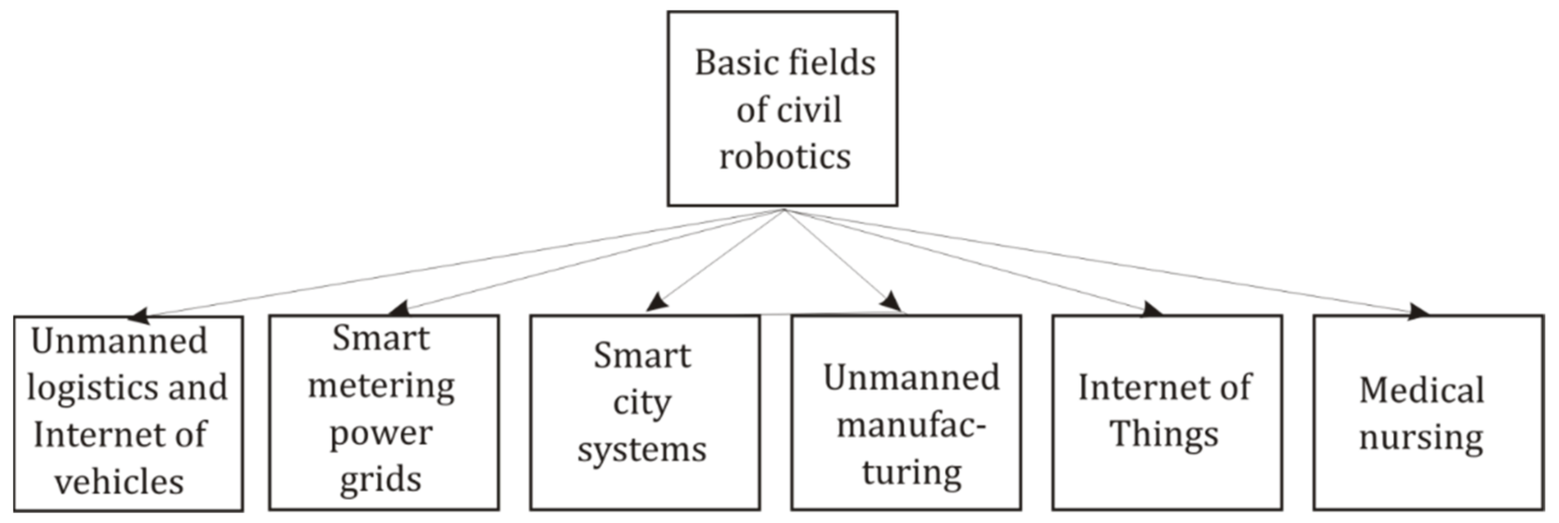
Figure 1. Basic fields of research for civil robotics.
Applsci 15 02427 g001
Figure 2. Distant MAS and its agents, A 1 , A 2 ,…, are considered within some scene of actions, containing other robots and MASs, people, animals, and various objects.
Applsci 15 02427 g002
Figure 3. (a) Complicated version of MVL proposed in [60] contains 6 truth levels with two non-comparable elements in lattice and was proposed for the design of temporal logic and Kripke structures. (b) Simple version of the linear truth levels scale was used in AGA [70], which is more convenient for the description of large-scale models of intellectual agents.
Applsci 15 02427 g003
Figure 4. Data error limitation for the choice of correlated variable, x ( l ) . (a) Correct mapping onto the scale of truth levels. (b) Case (b) differs from (a) by the large error value, where each of two groups of data can be classified both as 1 or 2. Incorrect mapping occurs if the statistical and measurement error,   δ , exceeds the difference between two close truth levels, i.e.,   δ k j k j 1 ,     j = { 2 , , K 1 } .
Applsci 15 02427 g004
Figure 5. (a) The simplified scheme of AGA-based LL formation [68,69], which includes the twice transfer of messages between the agent and network participants of the protocol. The list of possible participants should be formed in advance; it includes agents of the same MAS and network partners nodes. (b) The structure of logic AGA expressions, defining AGA-based versions of LL.
Applsci 15 02427 g005
Figure 6. Description of the scene of action by root and sequential chain vocabularies. (a) Mapping of arbitrarily selected root vocabularies, V 1,1 L V 1,1 N   V 1,1 K   , transferring natural language terminology onto scales of natural numbers and logic truth levels. (b) Chain mapping of vocabularies like V 1,1 L V 2,1 L V 3,1 L … is convenient for the content clarification and formation of structured word phrases. Every vocabulary, V v , m L , further has double index for compact matrix notation.
Applsci 15 02427 g006
Figure 7. The scheme of transitions from natural-number code to logic truth-level code is necessary for the heterogeneous logic architecture of the agent. Equal scales for natural numbers and truth levels make this transition just a formal step.
Applsci 15 02427 g007
Figure 8. (a) Two channels to provide separate access to internal data by more protected AGA truth-level codes and by simpler natural-number codes. (b) The principle of brief verification of vector components’ histogram in possessed and needed profiles for root vocabularies, V v N , V v K , and further chain ones.
Applsci 15 02427 g008
Figure 9. A highly simplified scheme of a robotic agent supposes the dialog exchange of messages with the distant administrator or another agent via the specialized communication module.
Applsci 15 02427 g009
Figure 10. Principal scheme of dialog messages exchange between sender (administrator or agent) and ad-dresser (distant agent). Format of requests and replies corresponds to Table 4.
Applsci 15 02427 g010
Figure 11. Formation of the AGA-based LL.
Applsci 15 02427 g011
Figure 12. Possible practical application for the verification of authenticity and credentials. Data procession combines AGA calculations, local LL data storages, and dialog communications of unmanned robots. Autonomous state or corporative regulator’s agent checks license number ID and freight parameters received from unmanned delivering agents and terminals.
Applsci 15 02427 g012
Figure 13. Two-dimensional logic diagram displays events classified only by logic constants 5 and 6 for the AGA function given in Table 2. This band of constants is limited by the criteria C k = 5,6 . To obtain convenient visuality, diagrams for close classes of objects may be preliminarily decoded into the natural-number code.
Applsci 15 02427 g013
Figure 14. Two dual-chip modules are necessary to process full-scale dialog phrases, based on the proposed vocabulary structure. Blue line is the common addressing 8-bit bus, and green line is the common data 8-bit bus. Bold black line is the output data bus and the digital feedback.
Applsci 15 02427 g014
Table 1. Basic format of the truth table defined in AGA [70].
rowInput VariablesOutput Variable
x 1 x 2 x 3 x 4 x n F ( x 1 , , x n )
000000 F ( 0 , , 0 )
110000 F ( 1 , , 0 )
K n 1 K − 1K − 1K − 1K − 1K − 1 F ( K 1 , , K 1 )
Table 2. Basic formal parameters for the description of the scene of action.
NotationDefinition
K Finite set of truth levels, K , is defined in AGA [70], where k = { 0 ,   1 ,   2 , ,   K 1 } , K N , and N is the set of natural numbers. Only finite sets are intended for basic logic AGA modeling and the mapping of words vocabularies.
V N Finite subset, v N , of the set of natural numbers, v N = { 1,2 , . , K } ,
V N N .   It is intended for auxilliary representation and mapping of words in vocabularies.
V L The finite set (or the vocabulary) of all selected different robotic terms, given by words and word collocations of natural language. It describes the scene of action, robotic tasks, and mathematical and verification procedures.
V v K Modeling of the scene of action uses v subsets of truth levels,   v = 1 , , K , obtained by arbitrarily chosen bijective mapping, V N K , i.e., onto the scale of truth levels, k = 0,1 , , K , defined in AGA.
V v N Subsets V v N   of vocabulary V N are obtained by arbitrarily chosen mapping of V L V N , i.e., onto the scale of natural numbers n N = { 1,2 , , K } , where the set V N consists of v subsets V v N V N , v = 1 , , K ;
V v L Subset V v L   of the vocabulary   V L   determines one of v given classes of robotic terms, containing only different elements, V v L V L ,   v = 1 ,   , V ,   V K , where K is the maximal number of truth levels. In the majority of tasks, convenient classes of robotic terms correspond to classes of words (noun, verb, adverbial modifiers of place, time, etc.)
w v L Element of a subset (or vocabulary) V v L   can be given by a word or a collocation, representing in natural language some robotic term.
w v N Mapping of w v L onto the subset of natural numbers V N , providing representation of a robotic term in natural-number code.
w v K Mapping of w v L onto the set K , providing equivalent logic representation of a robotic term.
W z Word phrase is a vector, W z   = ( w 1 , w 2 , …, w Z ) , with declared fixed position of elements according to their numbers, v = {1,..,Z}, Z   V K . Word phrase is a sampling of only one word from the next vocabulary. For various types of processions, it can be written by elements w v L , w v N ,   w v K   of subsets V v L , V v N , V v K . Note that the list of selected vocabularies and message format can differ for various classes of tasks.
Table 3. The structure of vocabularies, V v , m L , initially given in natural language is described as a matrix, K x M , where K is the initially chosen maximal number of truth levels in AGA.
NName of VocabularyContentClass of Word in Natural LanguageNatural Language Representation
(Maximal Number of Words—K)
1 V 1,1 L Initiation of dialog and format of messageCardinal number{one, two, …, K }
2 V 1,2 L Fixed paroleCardinal number{one, two, …, K }
3 V 1,3 L Hash valueCardinal number{one, two, …, K }
4 V 1,4 L Addresser of messageNoun{administrator, robot of MAS, external robot, man, vehicle, unidentified object}
5 V 1,5 L Sender of messageNoun{administrator, robot of MAS, external robot, man, vehicle, unidentified object}
6 V 1,6 L Relative time of sendingCardinal number{one, two, …, K }
7 V 1,7 L Time of actionAdverbial modifier of time{immediately, now, near future, in an hour, at the specified time…}
8 V 1,8 L Action/taskVerb{verify, measure, read, write, move to, upload, download, plugs/connectors check, software check, circuit board test, coating check, mechanics check, show word …}
9 V 1,9 L Object of actionNoun{admin, addresser, robot of MAS, external robot, man, house, technical construction, vehicle, road, tree, animal, vocabulary, unidentified object, license ID…}
10 V 1,10 L Number of objects of actionCardinal number{one, two, …, K }
11 V 1,11 L Place of action/objects of actionNoun, adverbial modifier of place{robot, external object, vehicle, internal module, …}
12 V 1,12 L Reference object for relative coordinatesNoun{robot of MAS, external robot, man, house, technical construction, vehicle, road, tree, bush, animal, pit, stone, …}
13 V 1,13 L Place of action/coordinate xCardinal number{GPS coordinate x, relative coordinate one, two, … ,   K }
14 V 1,14 L Place of action/coordinate yCardinal number{one, two, … ,   K }
15 V 1,15 L Linked listCardinal number{one, two, …, K }
16 V 1,16 L Natural-number codeCardinal number{one, two, …, K }
17 V 1,17 L Truth-level codeCardinal number{one, two, …, K }
18
M V 1 , M L
V 2,1 L Format of messageCardinal number{one, two, …, K }
V 2,2 L Fixed paroleCardinal number{one, two, …, K }
V 2,3 L Addresser of messageNoun{administrator, robot of MAS, external robot, man, vehicle, unidentified object}
2M V 2 , M L
KxM V K , M L
Table 4. The equivalence of words in vocabularies V v , m L , V v , m N   , and V v , m K   .
NNatural Language VocabularyNatural-Number Code of VocabularyTruth-Level Code of VocabularyContent
1 V 1,1 L V 1,1 N V 1,1 K Format of message
w 1,1 , 1 L w 1,1 , 1 N w 1,1 , 1 K “SOS”
w 1,1 , 2 L w 1,1 , 2 N w 1,1 , 2 K “Hi, read 2parts message”; Initiation of the new phrase
w 1,1 , 3 L w 1,1 , 3 N w 1,1 ,   3 K “Hi, read 3parts message”;
w 1,1 , 7 L w 1,1 , 7 N w 1,1 ,   7 K “Ready to continue”
2 V 1,2 L V 1,2 N V 1,2 K Fixed parole
K × M V K , M L V K , M N V K , M K Content given by expert
Table 5. Word phrase W K is to be written by the header and several content parts in the logic code, and formed by words taken from a sampling, K , of all defined K x M vocabularies. Notation w v , m K indicates a word with arbitrarily given indexes, v , m , chosen by the expert or decision-maker from some V v , m K .
1st 8-Byte Header Part
Variable x 1 x 2 x 3 x 4 x 5 x 6 x 7 x 8
NameInitiation of dialog/Format,
w 1,1
Fixed parole, w 1,2 Addresser
name 1,
w 1,4
Addresser
name 2,
w 2,4
Addresser
name 3,
w 3,4
Sender
name 1,
w 1,5
Sender
name 2,
w 2,5
Sender
name 3,
w 3,5
Vocabulary
(in Table 3)
V 1,1 K V 1,2 K V 1,4 K V 2,4 K V 3,4 K V 1,5 K V 2,5 K V 3,5 K
2D 8-Byte Content Part
Variable x 9 x 10 x 11 x 12 x 13 x 14 x 15 x 16
NameAssigned hash,
w 1,3
Arbitrary word,
w v , m
Arbitrary word,
w v , m
Arbitrary word,
w v , m
Arbitrary word,
w v , m
Total check coefficient of all previous parts and the current one,
C K or C N / K
Vocabulary V 1,3 K V v , m K V v , m K   V v , m K V v , m K V 1,17 K
(KxM-4)/2th 8-byte part-content
Variable x K 8 x K 7 x K 2 x K 1 x K
NameAssigned hash,
w 1,3
Arbitrary word,
w v , m
Arbitrary word,
w v , m
Arbitrary word,
w v , m
Arbitrary word,
w v , m
Total check coefficient of all previous parts and the current one ,     C K or C N / K
Vocabulary V 1,3 K V v , m K V v , m K V v , m K V v , m K V 1,17 K
Table 6. The example of the model phrase to clarify questionable license ID (truth number code = 196), corresponding to words codes w 3,12 N   and w 6,221 K in actual vocabularies V v , m N = 196 and V v , m K = 147 . Correct phrase consists of the header and one content part. Content part can be found in buffer memory even if it was received before the header.
Header: w 1,1 K w 1,2 K w 1,4 K w 2,4 K w 3,4 K w 1,5 K w 2,5 K w 3,5 K
Mapping to natural-number
code
Hi = 2Fixed parole of addresser = 131Addresser name 1 = 0Addresser name 2 = 0Addresser name 3 = 3Sender name 1 = 0Sender name 2 = 0Sender name
3 = 2
Content part 1: w 1,3 K w 1,8 w 1,9 w 2,9 w 3,9 w 1,15 w 1,3 C N / K   = ∑ w v , m
Mapping to natural-number
code
Assigned hash value = 209Action =
Show
K-code for word in V v , m N = 196
Number of objects = v = 3Number of objects = m = 12Number of objects = w v , m N = 6Questionable code name w v , m K = 221Hash for access to vocabularies group, including V v , m K = 147138 + 209 + 196 + 3 + 12 + 6 + 221 + 147 = 932 (overflow: >255);
932 − 3 × 255 = 167
Table 7. Necessary set of coded words to be written in the vocabulary’s structure.
“Extract Word”
Number of rows in vocabulary matrix,
v = 1
Number of columns in vocabulary matrix, m = 8Word code in natural language = w 1,8 L =
“Show variable”
Word code in natural-number code = w 1,8 N
= 23
Word code in truth levels =
w 1,8 K = 175
Addresser’s
approving
hash ,
h v , m , ( m , 0 ) = 34
Sender’s approving hash h v , m = 242
“License ID”
Number of rows in vocabulary matrix,
v = 1
Number of columns in vocabulary matrix, m = 9Word code in natural language = w 1,9 L =
“license ID”
Word code in natural-number code = w 1,9 N
= 23
Word code in truth levels =
w 1,9 K = 207
Addresser’s
approving
hash
h v , m , ( m , 0 ) = 11
Sender’s approving hash h v , m = 101
“Hash Value”
Number of rows in vocabulary matrix,
v = 1
Number of columns in vocabulary matrix, m = 8Word code in natural language = w 1,8 L   =
“hash value”
Word code in natural-number code = w 1,8 N
= 23
Word code in truth levels =
w 1,8 K = 175
Addresser’s
approving
hash
h v , m , ( m , 0 ) = 83
Sender’s approving hash h v , m = 75
Table 8. Structure of the truth table for adapted versions of LL, given by AGA function. (a) Version following basic definition of AGA-based LL [69]. (b) Version with replaced quasi-random hash values.
(a) Input VariablesOutput Variable
Word code in natural numbers,
w v , m N   =
{1 ÷ 16}
Number of rows in vocabulary matrix,
v = { 1 ÷ 16 }
Number of columns in vocabulary matrix, m = {1 ÷ 16}Word code in truth levels,
w v , m K = {1 ÷ 256}
Sender approving hash,
h v , m = {1 ÷ 256}
Addresser approving
hash
h ( m , 0 ) = {1 ÷ 256}
(b) Input VariablesOutput Variable
Word code in natural numbers,
w v , m N = {1 ÷ 16}
Number of rows in vocabulary matrix,
v = { 1 ÷ 16 }
Number of columns in vocabulary matrix, m = {1 ÷ 16}Addresser
approving
hash
h v , m , ( m , 0 )   = {1 ÷ 256}
Sender approving hash,
h v , m = { 1 ÷ 256 }
Word code in truth levels,
w v , m K = {1 ÷ 256}
Table 9. (a) The base version of AGA-linked list [69] and its truth table is defined by function   h ( m , 1 ) = F l d g ( m , t , e m , e m 1 , h m , h m 1 ). (b) Proposed shortened version of LL for documenting task parameters, transmitted by phrases, consisting of g parts and containing only check coefficients, C 1 , m 1 K , h e a d e r , C 2 , m 1 K , c o n t e n t , . ,   C g , m 1 K , t o t a l . Quasi-random hash values, h 1 ( 1,1 ) ,   , h 1 ( m , 1 ) , approve corresponding entries.
(a) Number of input variables: 2 × (1 + p + q), p-number of words in entry, q- maximal number of verifying participants
Input VariablesOutput
Variable
Common countersPrevious Entry (8 bytes)Verifying hashLast Entry (8 bytes)Verifying hashOutput hash
m t e 1 , t 1 e p , t 1 h 1 , t 1 h q , t 1 e 1 , t e p , t h 1 , t h q , t h ( m , 1 )
1 t 1 e 1,0 e p , 0 h 1 , 0 h 1 , 0 e 1,1 e p , 1 h 1 , 1 h Q , 1 h 1 ( 1,1 )
m − 1 t m 1 e 1 , m 2 e p , m 2 h 1 , m 2 h Q , m 2 e 1 , m 1 e p , m 1 h 1 , m 1 h Q , m 1 h 1 ( m 1,1 )
m t m e 1 , m 1 e p , m 1 h 1 , m 1 h Q , m 1 e 1 , m e p , m h 1 , m h Q , m h 1 ( m , 1 )
(b) Number of input variables: 2 × (2 + g), g-number of parts in the phrase.
Common countersPrevious Entry (8 bytes)Verifying hashLast Entry (8 bytes)Verifying hashOutput hash
Input variablesOutput
variable
m t C 1 , m 1 K , h e a d C 2 , m 1 K , c o n t C g , m 1 K , t o t a l h i , m 1 C 1 , m K , h e a d C 2 , m K , c o n t C g , m K , t o t a l h i , m h ( m , 1 )
1 t 1 C 1,1 C 2,1 C g , 1 h 1 , 1 C 1,2 C 2,2 C g , 2 h 1 , 2 h 1 ( 1,1 )
m − 1 t m 1 C 1 , m 2 C 1 , m 2 C g , m 2 h m 1 , m 2 C 1 , m 1 C 1 , m 1 C g , m 1 h m 1 , m 1 h 1 ( m 1,1 )
m t m C 1 , m 1 C 2 , m 1 C g , m 1 h m , m 1 C 1 , m C 2 , m C g , m h m , m h 1 ( m , 1 )
Table 10. Example of FMF F x 3 , x 4 , formed by striking out unnecessary variables in the holistic truth table. Mapping function is F x 1 , , x 5 , mapped one is F ( x 3 , x 4 ) , and restriction is C k = 5,6 .
Applsci 15 02427 i001
Table 11. Memory allocation table used for modeling of L L w r d .
NWord Code in Natural Numbers,
w v , m N = {1 ÷ 16}
Number of Row in Vocabulary Matrix,
v = { 1 ÷ 16 }
Number of Column in Vocabulary Matrix, m = {1 ÷ 16}Addresser
Approving
Hash,
h v , m , ( m , 0 ) = {1 ÷ 256}
Sender Approving Hash,
h v , m { = 1 ÷ 256 }
Word Code in Truth Levels,
w v , m K = {1 ÷ 256}
#A18–A16:#000b#000b#000b#000b#000b#000b
#SB (A15–A8):#109#108#107#106#105#104
#LB:#0 ÷ 255#0 ÷ 255#0 ÷ 255#0 ÷ 255#0 ÷ 255#0 ÷ 255
Table 12. SRAM buffer structure for received phrases’ 8-byte parts in the 2D dual-chip module. It can contain 30 written parts, obtained from the receiving module. #LB provides up to 256 possible code numbers for various words in a vocabulary.
Received Data BufferReserve for Intermediate
Calculations
NPart 1Part 2Part 30Results 1Results 2
#A18–A16:#000b000b000b000b000b
#SB (A15–A8):#111b#111b#111b#111b#111b
#LB (A7–A0):#0–7#8–15#233–239#240–247#248–255
Disclaimer/Publisher’s Note: The statements, opinions and data contained in all publications are solely those of the individual author(s) and contributor(s) and not of MDPI and/or the editor(s). MDPI and/or the editor(s) disclaim responsibility for any injury to people or property resulting from any ideas, methods, instructions or products referred to in the content.