Abstract
This study presents the design, development, and experimental assessment of soft pneumatic actuators for achieving bending motion utilizing vacuum pressure, with their final application to soft robotic grippers. A novel soft actuator design is introduced, satisfying the following design requirements: safe operation without the risk of explosion, the ability to achieve large angular bending while overcoming significant forces, and the use of soft materials that are resistant to material fatigue. A vacuum-driven soft bending actuator (VSBA) was designed, incorporating a cylindrical ribbed bellow geometry and an integrated limiting element within its structure. Two variations of the VSBA were fabricated, each differing in the materials and manufacturing processes employed. The first version employs a cylindrical ribbed bellow made of thermoplastic rubber (TPR), while the other versions utilize heat-shrinkable polymer materials, resulting in an innovative manufacturing process capable of producing actuators in various sizes and shapes. This contributes to the analysis of how actuator geometry affects performance and enables its miniaturization. The performance of the novel VSBAs were experimentally assessed through measuring the bending angle, blocking force, and angular velocity–angle characteristics. The results confirmed a maximum bending angle of 140° corresponding to a bending ratio of 78%, a maximum blocking force of 110 N, and maximum angular velocity of 520°/s at a vacuum pressure of −0.8 bar. Finally, a soft robotic gripper was developed, consisting of three newly designed VSBAs. Experimental assessments demonstrated the gripper’s capability to grasp objects of various shapes, with a maximum holding force of 28 N.
1. Introduction
Soft pneumatic actuators are versatile and flexible components that use compressed air to perform functional tasks, enabling multi-axis motion. Their ability to adapt to the object’s shape makes them especially well-suited for precise and delicate tasks in industrial manipulation and medical robotics. Current advancements in soft pneumatic actuators focus on addressing two major challenges: developing innovative design solutions and utilizing new soft materials with state-of-the-art manufacturing technologies [1,2,3,4,5].
In the pursuit of developing more flexible and lightweight actuators, various design solutions for soft pneumatic actuators have been proposed. These solutions are generally categorized into actuators that use positive or negative (vacuum) pressure or both simultaneously [6]. Soft pneumatic actuators using positive pressure can generate substantially higher forces due to their ability to operate with higher pressure values [7]. However, higher pressure increases the risk of material fatigue and actuator explosion due to the limited material strength [8,9,10]. To address this issue, soft pneumatic actuators utilizing vacuum pressure have been developed, with a maximum value of −1 bar [11,12,13].
Furthermore, design solutions of the soft pneumatic actuators vary depending on the type of motion they are intended to perform. Depending on application requirements, they can be designed for linear motion, bending, twisting, or a combination of these motions. Linear motion is typically achieved through the linear expansion or contraction of the actuator, driven by positive pressure [14,15] or vacuum pressure [16,17]. In contrast, angular bending involves two-axis or multi-axis motion and can be accomplished using various design approaches [18,19]. For two-axis bending motion, one approach utilizes an asymmetric actuator geometry that enables bending under positive pressure [20] or vacuum pressure [21,22,23]. Angular motion can also be achieved with a symmetric actuator design incorporating a flexible limiting element [24], which restricts contraction on one side, causing the actuator to bend.
A key factor in advancing soft pneumatic actuators is the selection of soft materials, which, when combined with innovative manufacturing techniques, significantly accelerates their development [25]. Silicone rubber, one of the most widely used materials, offers exceptional elasticity, allowing actuators to be fabricated by casting into custom molds to achieve desired shapes and dimensions. For example, studies [26,27] employed this method to produce multi-chamber soft pneumatic bending actuators integrated into the soft robotic gripper. Similar results were reported in [28,29], highlighting the conclusion that silicone rubber-based actuators typically operate at pressures under 1 bar, as higher pressures pose a risk of actuator explosion.
Another method for fabricating soft pneumatic actuators is 3D printing with flexible materials. In the study [30], flexible thermoplastic elastomers (TPE) were used to fabricate a cell-based soft bending actuator. Furthermore, ref. [31] showed that pneumatic actuators of similar shape made from thermoplastic polyurethane (TPU) exhibited superior resistance to fatigue compared to those made from silicone rubber, withstanding up to 6400 cycles. However, ensuring actuator durability for real mechatronic systems requires materials with proven long-term performance. In [32,33], commercially available ribbed rubber bellows, certified for durability by the manufacturer, were employed in the design of soft pneumatic actuators. Similarly, ref. [34] fabricated a soft pneumatic actuator using a heat-shrinkable material, with experimental results indicating the ability to achieve up to 150,000 operational cycles with minimal material degradation. The comparison of the mechanical properties of previously mentioned soft bending actuators is shown in Table 1. Please note that in some studies, the authors did not analyze both the bending angle and the force, and in the last actuator, positive and negative pressure were used simultaneously.

Table 1.
Mechanical properties (maximum) of previously developed soft bending actuators.
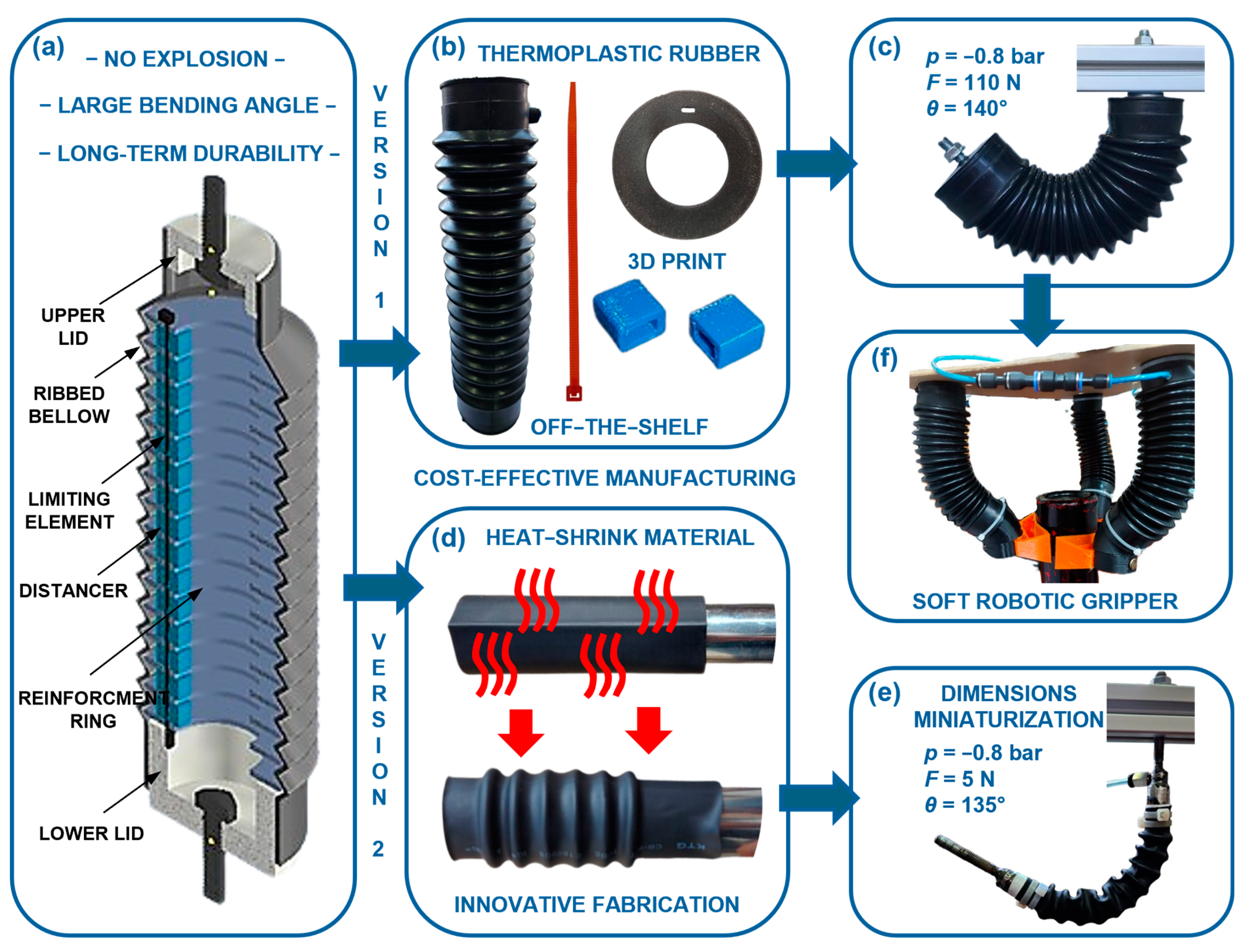
This paper presents the design and development process of soft pneumatic actuators that achieve bending motion. Our contribution advances soft pneumatic actuator development, demonstrated through the innovation of simple, cost-effective, and efficiently designed actuators that meet the following design requirements. An innovative actuator design was developed to ensure safe operation without the risk of explosion, enable large bending motion while generating significant forces, and incorporate soft materials that are resistant to fatigue. The first two requirements were fulfilled by applying vacuum pressure and the ribbed bellow geometry, with an integrated limiting element within the actuator. The third requirement was achieved utilizing thermoplastic rubber and heat-shrinkable materials, whose durability has been verified by the manufacturer. Using heat-shrinkable material led to the development of an innovative manufacturing process, enabling the fabrication of actuators in various sizes and shapes. This contributed to analyzing how actuator geometry influences its performance and the possibilities for actuator minimization. Additionally, a soft robotic gripper consisting of three novel VSBAs was developed to analyze the performance of the VSBA in a real mechatronic system. The design approach used in this research is summarized graphically in Figure 1.
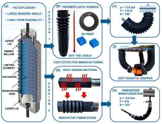
Figure 1.
Development and experimental assessment of VSBAs: (a) 3D model of the design with its main elements; (b) utilizes a thermoplastic rubber bellow and 3D-printed parts; (c) operation and performance of the VSBA that uses a thermoplastic rubber bellow; (d) a new approach for fabricating the ribbed bellow using a heat-shrinkable material; (e) operation and parameters of the smaller-sized VSBA produced with heat-shrinkable material; (f) soft robotic gripper utilizing VSBAs.
The remainder of the paper is organized as follows: Section 2 describes the materials and methods, including the design and fabrication of the VSBAs and the preliminary tests conducted. Section 3 presents experimental results of bending angle, blocking force, and angular velocity–bending angle characteristic under varying vacuum pressure and external loads. In Section 4, the application of the VSBA in a soft robotic gripper is presented, along with experimental assessments. Finally, Section 5 summarizes the main conclusions.
2. Materials and Methods
In this section, the design and development of soft pneumatic actuators with bending motion is presented. Based on three design requirements and a conceptual design approach, two novel VSBA actuators were developed and fabricated. The first approach utilizes thermoplastic rubber material, while the second uses heat-shrinkable material.
2.1. Design and Development of a Vacuum-Powered Soft Bending Actuator Utilizing Thermoplastic Rubber Material
After a methodical analysis of existing design solutions for soft bending actuators, it was observed that, despite their advantages, certain disadvantages still exist. The aim of this paper is to address these weaknesses through the development of a novel soft bending actuator that will meet three key design requirements. The first design requirement ensures safe operation without the risk of explosion, which can occur when positive pressure is used. As an alternative, vacuum pressure of up to −1 bar is used. While this limits the actuator’s maximum force, it reduces the risk of failure. Based on this safety requirement, it was decided that our VSBA would utilize vacuum pressure.
The second design requirement focuses on achieving a large bending angle while being able to overcome significant forces relative to the actuator’s dimensions. According to Pascal’s law, since vacuum pressure is limited, the actuator’s force can only be increased by expanding its dimensions. However, the external dimensions of the VSBA must remain limited due to spatial constraints in real mechatronic systems. To address this, cylindrical ribbed geometry, also known as ribbed bellow, was used to increase surface area without expanding external dimensions. To achieve bending motion of the VSBA, a solution with a limiting element was chosen, which constrains contraction on one side of the actuator when vacuum pressure is applied, causing it to bend. The limiting element is located within the actuator and is designed as a flexible thin square strip.
The third design requirement involves the use of soft materials that ensure actuator flexibility and durability without material fatigue. Therefore, we decided not to manufacture the ribbed bellow by casting silicone rubber or 3D printing with flexible materials. Instead, we focused on utilizing a commercially available ribbed bellow, with material durability verified by the manufacturer. The protection of the front suspension on motorcycles was chosen, as it meets the required geometric characteristics and material properties. This component is made from thermoplastic rubber (TPR) in large quantities using an injection molding process, which results in low cost. Also, thermoplastic rubber can withstand temperatures from around −30 °C to 120 °C without significant damage or changes in properties. An additional advantage of using this component is its ability to return the actuator to its initial position after the vacuum is released due to its low stiffness. The mentioned advantages, along with other beneficial properties, have already been confirmed in our previous research [32,35].
Based on the mentioned design solution, the VSBA was developed, and its 3D model with main elements is shown in Figure 1a. To ensure the airtightness of the VSBA, the ribbed bellows must be sealed at both the top and bottom. Following that, upper and lower lids were designed, which not only seal the actuator but also transfer force to the mechatronic system via screws passing through both lids. Vacuum pressure on the ribbed bellow causes axial and radial contractions, with radial contractions negatively impacting the VSBA geometry and reducing the actuator’s performance. To address this, reinforcement rings were designed and inserted along the inner side of the bellows. Additionally, reinforcement rings are designed with pockets through which the limiting element passes. The limiting strip should be tightly fixed with all rings at identical distances, as any deviation could cause uneven VSBA bending. Achieving this is challenging, so we implemented an innovative design with a distancing element (distancer) between the rings, through which the limiting strip passes, ensuring equal spacing.
The selected ribbed bellow has an outer diameter of 55 mm, a length of 200 mm, and a wall thickness of 2 mm. All other actuator parts, such as the lids, reinforcement rings, and distancers, were made using 3D printing with PLA filament, while a zip tie was chosen for the limiting element due to its good flexibility properties, as shown in Figure 1b. An existing hole in the ribbed bellows was used to mount the supply vacuum hose.
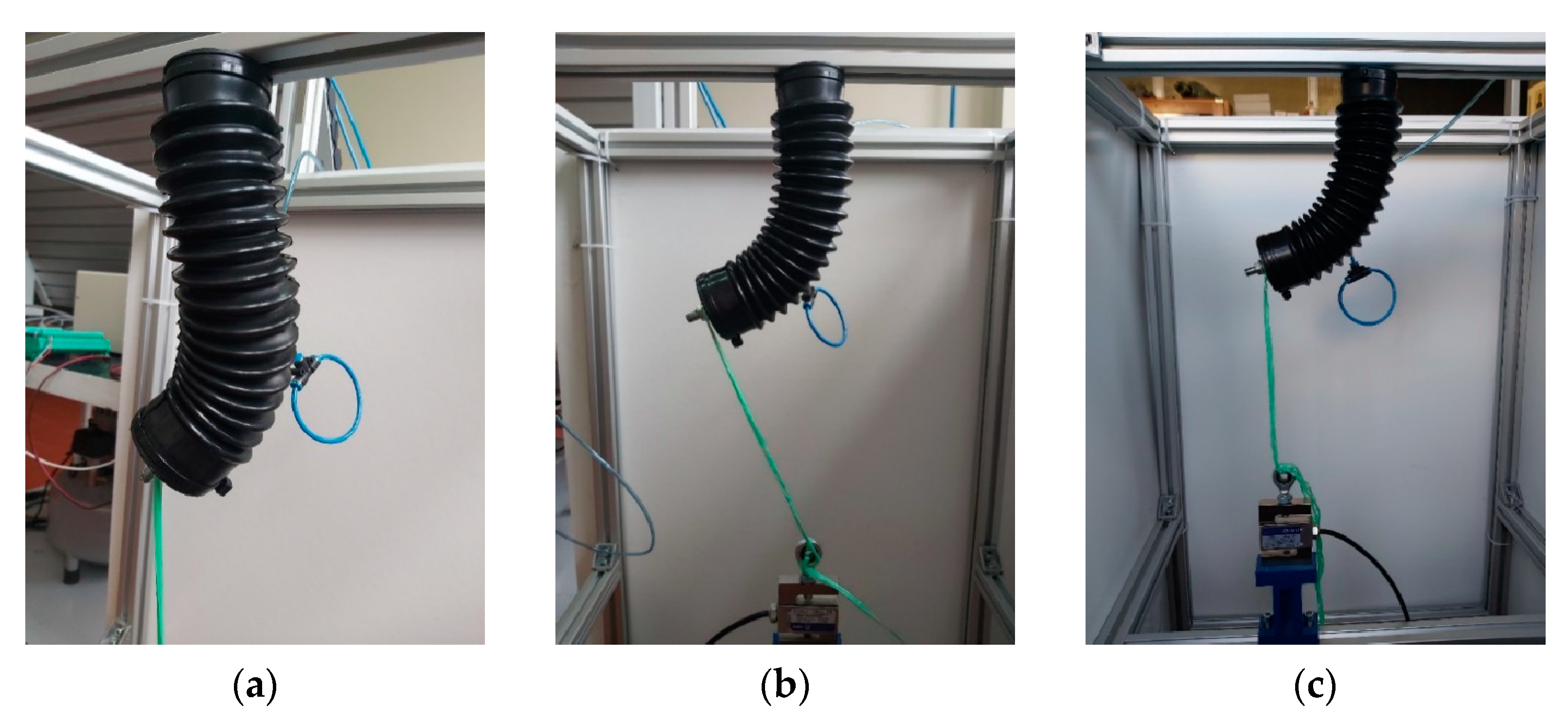
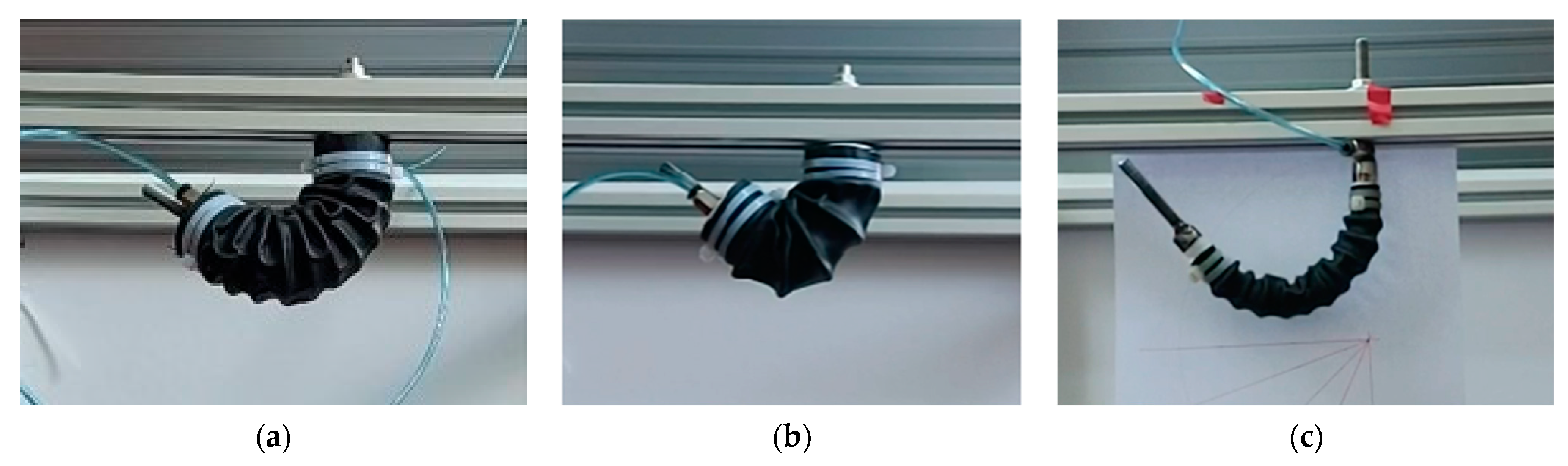
The fabricated first version of the actuator (VSBA-1) was tested for airtightness, and preliminary performance measurements were conducted. For experimental measurements, a laboratory structure made of aluminum profiles was used to securely anchor one end of the VSBA while positioning the load cell relative to the other movable end, as shown in Figure 2. While measuring the maximum blocking force of soft pneumatic actuators, they often deform [32], which was also observed in this experiment. This deformation occurs due to the method of measuring the blocking force, where the VSBA’s movement is restricted in the operating axis, causing it to deform in another axis due to its flexible structure, as shown in Figure 2a. It was found that this effect is significantly influenced by the position of the load cell, which, in the initial measurements, was aligned with the VSBA’s axis, as shown in Figure 2b. This led to the movement of the load cell to a new position, ensuring that the actuator force always acts perpendicular to the load cell’s axis (Figure 2c). This action eliminates VSBA deformation at all angles and vacuum values.
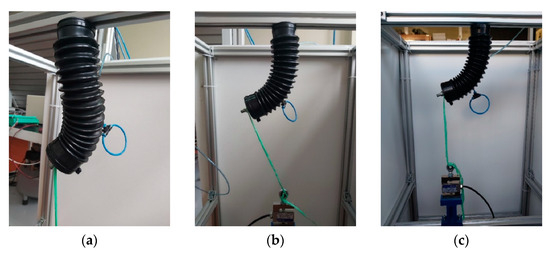
Figure 2.
Experimental assessment of blocking force: (a) deformation of VSBA; (b) measurements with the load cell and VSBA aligned on axis; (c) new load cell position eliminated deformation.
The results demonstrated a maximum bending angle of 140° and maximum force of 110 N at a vacuum pressure of −0.8 bar, as shown in Figure 1c. A cyclic fatigue test was also conducted, during which the VSBA-1 was cyclically activated for 60 min and achieved up to 1200 cycles. The test was carried out by activating the VSBA-1 with a vacuum pressure of −0.8 bar, causing it to bend to its final position. After that, the vacuum was released, and the VSBA-1 returned to its initial position. Finally, a visual inspection of the ribbed bellow was conducted, and the results showed no material fatigue.
The proposed design of the VSBA-1 successfully met all the specified requirements, effectively addressing the shortcomings identified in other soft pneumatic actuator designs. The only limitation of the VSBA-1 design is the standardized dimensions of the commercial ribbed bellows, restricting the fabrication of smaller-sized actuators. To address this limitation, we will develop a VSBA utilizing soft heat-shrinkable materials to enable its miniaturization.
2.2. Design and Development of a Vacuum-Powered Soft Bending Actuator Utilizing Heat-Shrinkable Material
An innovative fabrication approach using heat-shrinkable material will be implemented to develop a new VSBA with reduced dimensions compared to the VSBA-1. Made from polyolefin, this material has the ability to shrink when exposed to heat, enabling the fabrication of actuators in various shapes and dimensions. Furthermore, heat-shrinkable material is flexible and notable for its high durability and resistance to fatigue. Heat-shrinkable materials are commonly used in electrical installations to provide wire insulation and are typically available as tubes with standardized dimensions. Accordingly, heat-shrinkable tubes of various sizes will be employed in the fabrication of new VSBAs.
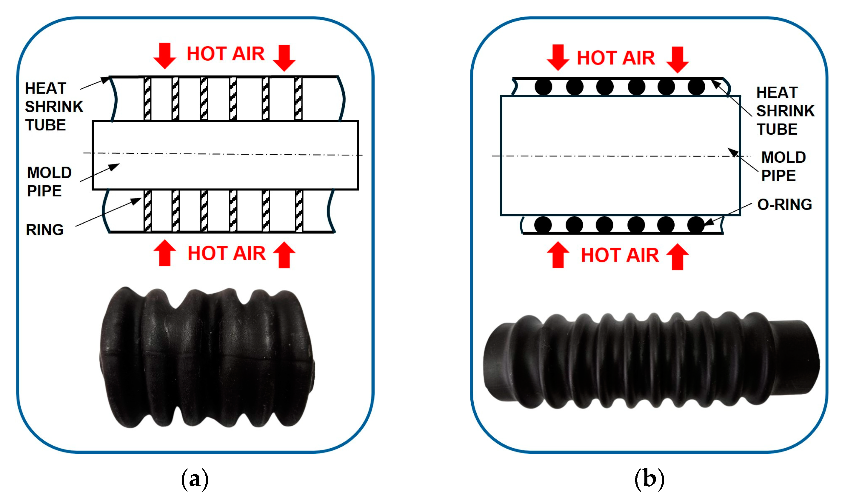
We present two innovative manufacturing methods for fabricating the ribbed bellow of a VSBA using heat-shrinkable tubes. The first method involves positioning reinforcing rings on a cylindrical pipe, after which the heat-shrinkable tube is placed over the rings, as shown in Figure 3a. After heating, the tube shrinks and bonds tightly to the rings, creating an actuator with a ribbed bellows geometry. The goal of this method was to create a compact actuator without the need for an additional reinforcing ring assembly, but its practical application proved challenging. The main challenge appears because the heat-shrinkable tube shrinks until it makes contact with some constraint, which makes it difficult to achieve a uniform ribbed bellows shape. Therefore, the final shape of the bellows primarily depends on the amount of heat applied. Additionally, when the tube shrinks by more than 50% of its initial diameter, the heat-shrinkable material becomes stiffer, reducing the actuator’s flexibility.
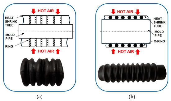
Figure 3.
Fabrication of the VSBA ribbed bellow utilizing heat-shrinkable tubes: (a) the first method with non-removable rings; (b) the second method, which uses a mold.
To address this drawback, a second method was developed in which the heat-shrinkable tube conforms to the shape of a mold, as shown in Figure 3b. The mold is made of O-ring seals that are placed on the pipe at equal distances, with the heat-shrinkable tube placed over them. After heating and shrinking the tube, the mold is removed, resulting in the ribbed bellows shape. Reinforcing rings are then inserted into the newly formed ribbed bellows. This method allows for precise control over the tube’s shrinkage, thereby sustaining the material’s initial flexibility. Furthermore, the second method facilitates the easy fabrication of ribbed bellows in various sizes and shapes. Before developing actuators with reduced dimensions, a VSBA-2 with the same dimensions and shape as the previous VSBA-1 will be created, with the goal of comparing their performance and feasibility of production a VSBA with heat-shrinkable material. Next, the VSBA-3 version was fabricated, maintaining the same outer diameter as the VSBA-2, but incorporating increased spacing between the bellows ribs to evaluate the effect of this spacing on the VSBA’s performance. Finally, a compact VSBA-4 version with a 50% reduction in outer diameter was fabricated.
To fabricate the VSBA-2, a standardized heat-shrinkable tube with an outer diameter of 50.8 mm and a wall thickness of 2 mm was selected, as it closely matches the dimensions of the VSBA-1. The mold dimensions were selected as follows: the pipe has an outer diameter of 39 mm, and standard 5 × 39 O-rings were selected, resulting in a total mold outer diameter of 49 mm. Additionally, the mold was created with ten O-rings spaced 8 mm apart, corresponding to the ribbed bellow shape of the VSBA-1 (Figure 3b). The selected heat-shrinkable tube starts shrinking at a temperature of 90 °C, so an industrial hot air blower was used to heat it, yielding the best results. Alternative heating methods, such as an open flame or hot water, have proven to be less effective. It was found that air trapped between the heat-shrinkable tube and the mold pipe during shrinking prevented shape formation, so holes were drilled along the pipe to allow air to escape. New reinforcing rings were made from steel, 2 mm thick, using a laser cutter. The distancers were made from small steel pipes, and the lids were manufactured from steel pipe with threaded rods welded on. To improve sealing, the outer edges of the lids were wrapped with seal tape, and zip ties were applied around the outer surface of the VSBA.
The fabricated VSBA-2 was tested for airtightness, and preliminary performance measurements were conducted (Figure 4a). The experimental results confirmed complete airtightness, a maximum bending angle of 120°, and a maximum force of 50 N at a vacuum pressure of −0.8 bar. When comparing the results to the VSBA-1, it is observed that the maximum force is 55% lower, and the maximum bending angle is 7% smaller, due to a smaller outer diameter and larger stiffness of the heat-shrinkable material. However, the VSBA-2 still demonstrates impressive performance, achieving a significant maximum bending angle and force. The following fabricated VSBA-3 has the same length and outer diameter as the VSBA-2, but with an increased spacing between the ribs, from the previous 8 mm to a new 20 mm. This modification resulted in an actuator with 5 ribs, compared to the previous 10 (Figure 4b). Preliminary measurements confirmed a maximum bending angle of 130° and a maximum force of 46 N. These results indicate that increasing the spacing between the ribs allows the VSBA-3 to achieve a larger bending angle (8% increase), but with a slightly reduced force (8% decrease) compared to the VSBA-2. This decrease in force is attributed to the reduced number of ribs, which decreases the surface area of the VSBA-3.

Figure 4.
Operating principles of (a) VSBA-2; (b) VSBA-3; (c) VSBA-4.
As already mentioned, we aimed to develop a smaller-sized actuator for the VSBA-4 than the previous ones, as shown in Figure 4c. A heat-shrinkable tube with an outer diameter of 27 mm was selected, resulting in an outer diameter of 25 mm for the VSBA-4. This represents a 50% reduction compared to the VSBA-2 and VSBA-3 versions, and a 54% reduction compared to the VSBA-1. The new mold was created using a pipe with an outer diameter of 14 mm and 5x14 O-rings, achieving the same rib rounding as the VSBA-2 and VSBA-3. For consistency in comparison, the ten ribs were kept the same as in the VSBA-2. The newly fabricated reinforcing rings have an outer diameter of 23 mm, while the lids were modified for smaller dimensions and designed with side openings for tube connections. Experimental results showed a maximum bending angle of 135°, representing a 4% increase compared to the VSBA-2. The maximum force achieved is 4.6 N, which is expected given the significant reduction in the dimensions of the VSBA-4. Additionally, 60-min cyclic fatigue tests were conducted on the VSBA-2 (660 cycles), VSBA-3 (900 cycles), and VSBA-4 (720 cycles), and the results indicated no signs of material fatigue or changes in their performance. The test was performed using the same procedures as the previously conducted fatigue test for the VSBA-1. Finally, it can be concluded that the VSBA using heat-shrinkable materials yielded encouraging results, which will be further analyzed in the following chapter through detailed experimental assessments.
3. Experimental Results and Discussion
Experimental assessments were conducted at the Hydraulic and Pneumatic Laboratory at the University of Rijeka, Faculty of Engineering, using the following pneumatic equipment: a CECCATO CSM 7.5 compressor with an air preparation unit, a FESTO VPPI-5L-G18-1V1H-V1-S1D proportional pressure control valve, and a FESTO VN-05-H-T2-PQ1-VQ1-RQ vacuum ejector. For data collection and processing, measurement equipment including the National Instruments NI myRIO 1900 device, Zemic H3G-C3-50kg-6B load cell, and Intel RealSense Depth Camera D455 were used. The laboratory pneumatic setup used a vacuum ejector to generate vacuum pressure, and for the specified FESTO vacuum ejector, the maximum vacuum pressure was −0.8 bar. Furthermore, the proportional pressure valve was used for precise control of the vacuum pressure in the range of 0 to −0.8 bar for the VSBA. A Virtual Instrument (VI) for controlling the used proportional pressure regulator and collecting measurement data was developed in the LabVIEW programming environment. This pneumatic setup presents a system with direct vacuum control, which is described in detail in our previous study [35]. Two types of experimental measurements were conducted under varying vacuum pressure values and different loading conditions: the first measured the maximum blocking forces at different bending angles, while the second investigated the angular velocity–bending angle characteristic.
3.1. Experimental Assessment of a Maximum Blocking Force
Experimental measurements were conducted for VSBA bending angles ranging from 15° to 90°, in 15° increments. The polypropylene rope was used due to its resistance to stretching, and its length was precisely measured and adjusted to match the actuator’s bending angle during the blocking force measurements. Vacuum pressure values varied from −0.1 to −0.8 bar in increments of −0.1 bar.
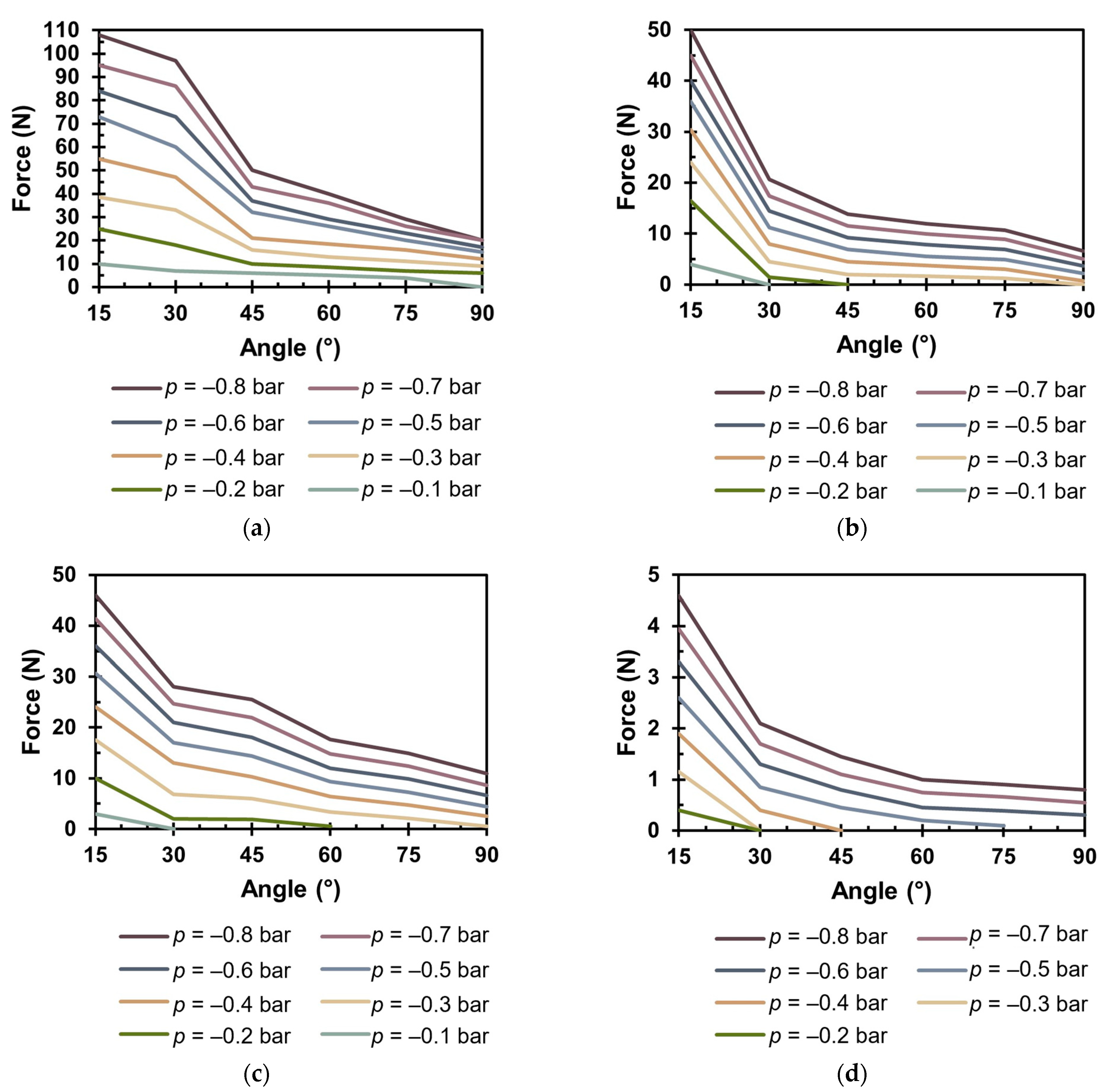
The maximum blocking force results for the VSBA-1 are presented in Figure 5a. These results indicate that the maximum blocking force occurs at an angle of θ = 15°, and as the bending angle increases, the force decreases for all vacuum values. This occurrence is due to two effects: first, the effect of vacuum pressure on the ribbed surface, producing both horizontal and vertical force components. The triangle ribs have the maximum angle in the actuator’s initial position; as the bending angle increases, the rib angle decreases, which directly reduces the vertical force component and, consequently, the total force. The second effect is result of an increasing resisting force within the actuator as the bending angle increases, which is caused by the material’s increased stiffness during deformation. Also, the ribs on the actuator bending side move closer, (see Figure 1c), which further contributes to the increase in resisting force, evident from the pronounced decrease in maximum blocking force observed between bending angles of 30° and 45°.
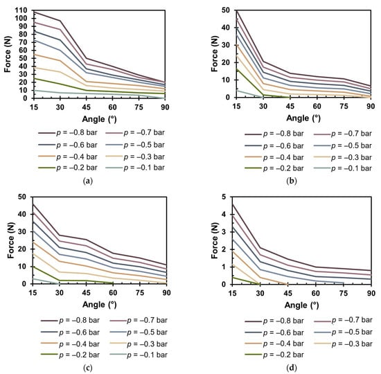
Figure 5.
Results of maximum blocking force: (a) VSBA-1; (b) VSBA-2; (c) VSBA-3; (d) VSBA-4.
The maximum force was achieved at a vacuum pressure of p = −0.8 bar, reaching F = 108 N at an angle of θ = 15°. As the bending angle increased to θ = 90°, the force decreased to F = 20 N. The results show that at an angle of θ = 90°, the force is approximately 20% of the maximum value, leading to the conclusion that further force measurements would not be conducted. Also, for blocking force measurement above 90°, repositioning the load cell is needed to ensure the correct angle between the rope and the screw on the lower lid.
The following experimental assessments of maximum blocking force were performed for VSBAs made from heat-shrinkable material. The measurements were conducted using the same procedure, with identical bending angles and vacuum pressures as in the previous experiment. The maximum blocking force results for the VSBA-2 are shown in Figure 5b. The results again indicate that the maximum blocking force is reached at a smaller bending angle across all vacuum values. Similar to the VSBA-1, a decrease in force with increasing angle was observed. However, for the VSBA-2, the force reduction is more significant between angles of 15° and 30°. Compared to the VSBA-1, the maximum blocking force is reduced, primarily due to slightly smaller dimensions and increased stiffness of the heat-shrinkable material. The maximum blocking force, achieved at p = −0.8 bar, is F = 50 N at an angle of θ = 15°, while at an angle of θ = 90°, the force is F = 6.6 N.
The maximum blocking force results for the VSBA-3, which has the same outer diameter as the VSBA-2 but features increased rib spacing, are shown in Figure 5c. A comparison of the measurement results shows that the VSBA-2 achieves a slightly higher maximum blocking force at θ = 15° angle, while the VSBA-3 generates higher blocking forces at all other bending angles. This performance of the VSBA-3 is attributed to the increased rib spacing, which reduces ribs contact and consequently decreases the resisting force. The maximum blocking force of F = 46 N was achieved at θ = 15° and p = −0.8 bar, while at an angle θ = 90°, the maximum blocking force is F = 11 N.
The experimental results for the VSBA-4, which has a 50% smaller outer diameter compared to the previous versions, are shown in Figure 5d. The results prove that the reduced diameter of the actuator results in a decrease in the maximum blocking forces. Additionally, it is evident that at lower vacuum values, such as p = −0.3 bar, the actuator is unable to overcome the resisting force for bending angles greater than θ = 30°. At a vacuum pressure of p = −0.1 bar, the VSBA-4 achieved a bending angle of less than 15°, so this measurement was excluded. The maximum blocking force achieved is F = 4.6 N at p = −0.8 bar and θ = 15°, while at θ = 90°, the force is F = 0.8 N. A comparison of the VSBA-4 results with those of the previous actuators reveals identical dynamics, despite the significant reduction in diameter, thereby confirming the feasibility of manufacturing actuators with smaller dimensions utilizing heat-shrinkable material.
3.2. Experimental Assesment of Angular Velocity–Bending Angle Characteristic
Compared to the previous experimental assessment, this chapter analyzes the actuator’s performance in actual working conditions. This means that the movement of the actuator’s lower part is no longer constrained by the rope, allowing it to move freely to its final position. Therefore, the actuator was mounted on the profile structure as before, with a camera added to the same structure to capture its bending motion. The camera was used due to the complexity of using a sensor that could reliably measure the VSBA bending angle. The bending angles over time were determined using software the Microsoft Clipchamp 4.0 for video analysis (https://clipchamp.com/en/, accessed on 17 January 2025).
The experimental measurements of bending angles over time were conducted at vacuum pressure values ranging from −0.2 to −0.8 bar. At a vacuum pressure of p = −0.1 bar, all versions of the VSBA achieved only a small bending angle after a long time, so this measurement was excluded. Although the velocity of pneumatic actuators is a function of the airflow, according to the orifice equation, airflow depends on the pressure drop at the orifice. Therefore, the actuator’s velocity was analyzed as a function of pressure, as proportional pressure control valve dynamics used in the experimental setup can described by the orifice equation. Additionally, the experimental assessments were first conducted without an external load and then with an external load.
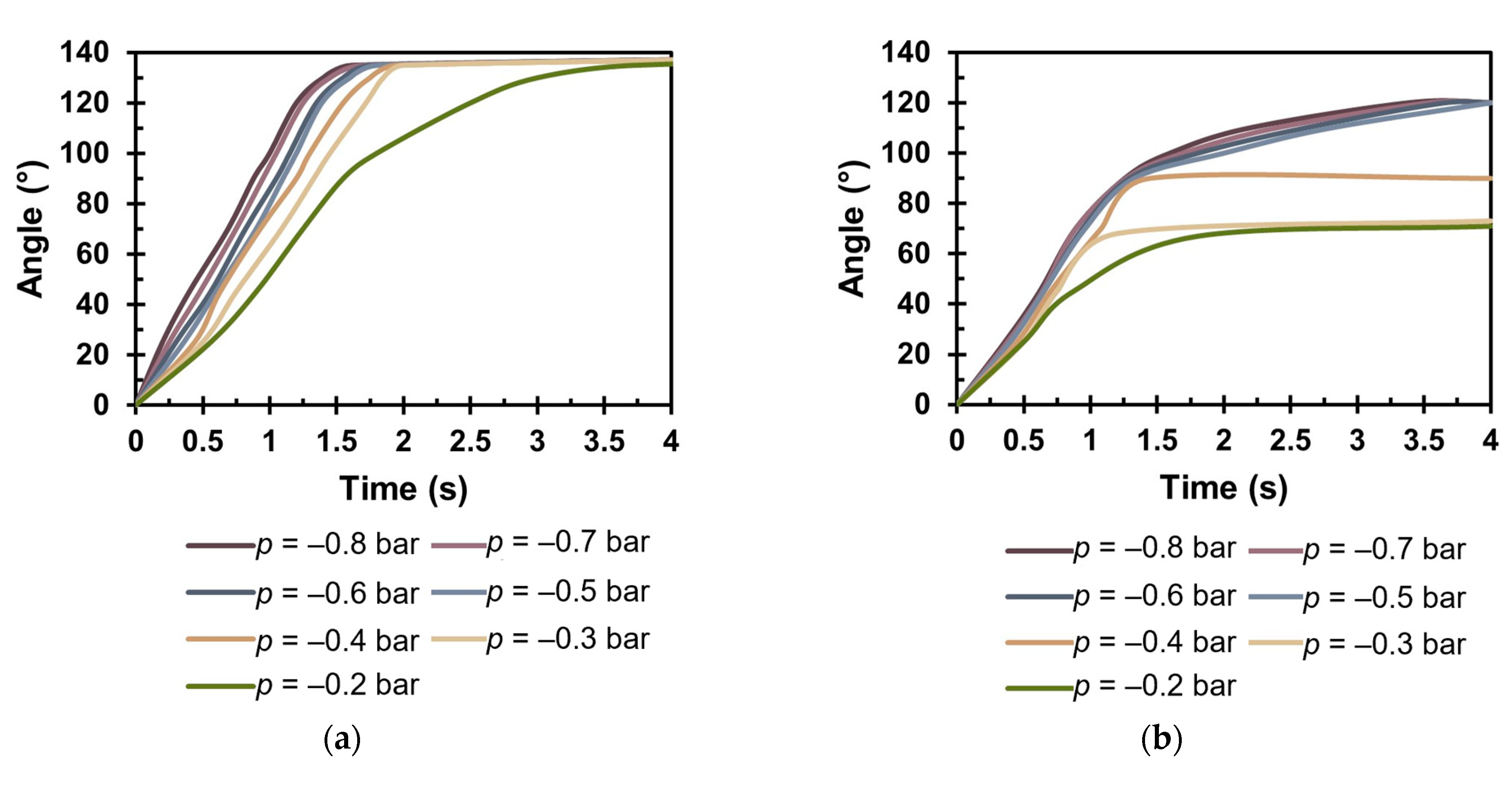
The results of the experimental measurements for the VSBA-1 without load are shown in Figure 6a. The results determined that for all vacuum pressure values, the VSBA-1 achieves a maximum bending angle of θ = 140°. However, it is evident that the VSBA-1 achieves 97% of the maximum bending angle in 1.6 s at p = −0.8 bar, demonstrating the actuator’s very fast response. As the vacuum pressure decreases, the time increases: at p = −0.2 bar, the time is 3.7 s. Also, it is notable that a nearly linear relationship between bending angle and time was observed up to an angle of θ = 120° for vacuum pressures ranging from −0.3 bar to −0.8 bar. Further experiments were conducted on the VSBA-1 with a 0.5 kg load to investigate the actuator’s behavior under real load conditions. The results showed the same operating dynamics, but with a reduced maximum bending angle of θ = 135° at p = −0.8 bar and a longer time of 3.1 s (Figure S1a is provided in the Supplementary Materials), approximately 50% longer than without a load. The results of the maximum bending angle for different values of vacuum are provided in Table 2 for cases with and without external load.
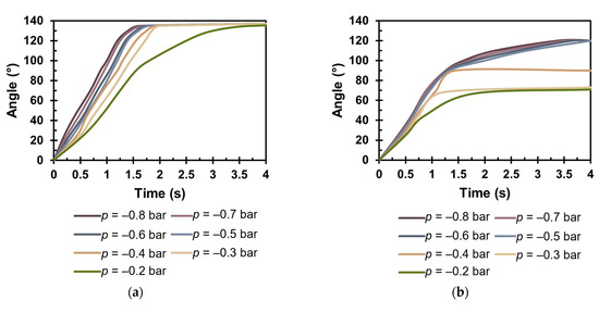
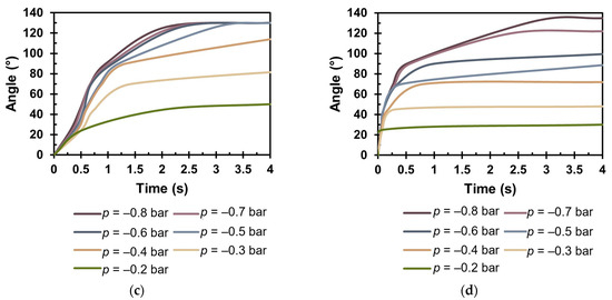
Figure 6.
Bending angles over time for actuators without load: (a) VSBA-1; (b) VSBA-2; (c) VSBA-3; (d) VSBA-4.
Table 2.
Maximum bending angle (in degree) with and without external load.
The following laboratory measurements were conducted for the VSBA-2 without load, and the results are shown in Figure 6b and Table 2. The results indicate that the actuator achieves a maximum bending angle of θ = 120° at p = −0.8 bar, requiring 3.5 s—about 57% more time compared to the VSBA-1. Also, when comparing the time required to reach 97% of the maximum bending angle, the VSBA-2 takes about 60% more time than the VSBA-1, demonstrating that the VSBA-2 has a slower response. Additionally, it is noticeable that the actuator reaches θ = 90° (approximately 75% of the maximum bending angle) in 1.2 s, after which it requires 2 s to reach the final position. This operating dynamic results from the increased stiffness of the heat-shrinkable material and for bending angles greater than 90°; the resisting force increases significantly, requiring more time to reach the final position. For the experimental assessment of the VSBA-2 with a 0.5 kg load, the maximum bending angle is θ = 90°, and a longer time was required to reach it (Figure S1b in the Supplementary Materials). For p = −0.8 bar, the θ = 90° was reached in 4.3 s, which is about 20% more time compared to the VSBA-2 without load. Additionally, at higher vacuum pressures, a linear bending angle-time relationship was observed up to approximately 66% of the maximum bending angle, with and without load.
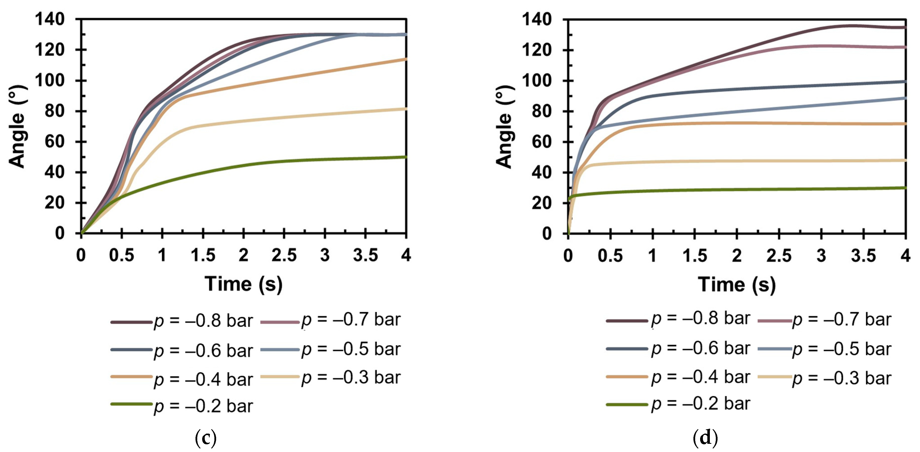
The experimental assessments for the VSBA-3, featuring larger rib spacing, are presented in Figure 6c and Table 2. The results once again confirm the advantage of larger rib spacing, which allows for a higher maximum bending angle of θ = 130° in 2.1 s (p = −0.8 bar), which is 40% shorter than the time required for the VSBA-2. Also, for vacuum pressures between −0.5 and −0.7 bar, shorter times were observed to reach the maximum angle in comparison with the VSBA-2. However, for vacuum pressures between −0.2 and −0.4 bar, the VSBA-3 was unable to reach maximum bending angle. An experimental result of the VSBA-3 with a 0.5 kg load demonstrated an operational dynamic similar to that without load. At p = −0.8 bar, the same maximum bending angle of θ = 130° was achieved after 4.5 s, which is about 55% more time compared to the case without a load (Figure S1c in the Supplementary Materials).
The results of the laboratory assessments for the VSBA-4 are shown in Figure 6d and Table 2. As previously mentioned, among all the VSBAs made from heat-shrinkable material, the VSBA-4 achieves the largest bending angle of θ = 135°, taking 2.7 s to reach this angle at p = −0.8 bar. Compared to the VSBA-2, the VSBA-4 achieves the maximum bending angle in 23% less time. Furthermore, it was observed that the VSBA-4 reaches 70% of its maximum bending angle in less than 0.5 s, representing performance not seen in previous actuator versions. This characteristic arises from the smaller surface area of the VSBA-4 exposed to airflow, which, according to the continuity equation, results in a higher velocity. Experimental measurements were also conducted on the VSBA-4 with a load of 0.1 kg, because the VSBA-4 could not overcome the 0.5 kg load. A similar dynamic as in the case without load was confirmed. At p = −0.8 bar, a maximum bending angle of θ = 90° was achieved in 2.4 s, which is about 12% more time compared to the unloaded case (Figure S1d in the Supplementary Materials). A linear angle–time relationship is observed up to an angle of 30° in both experiments, with and without load.
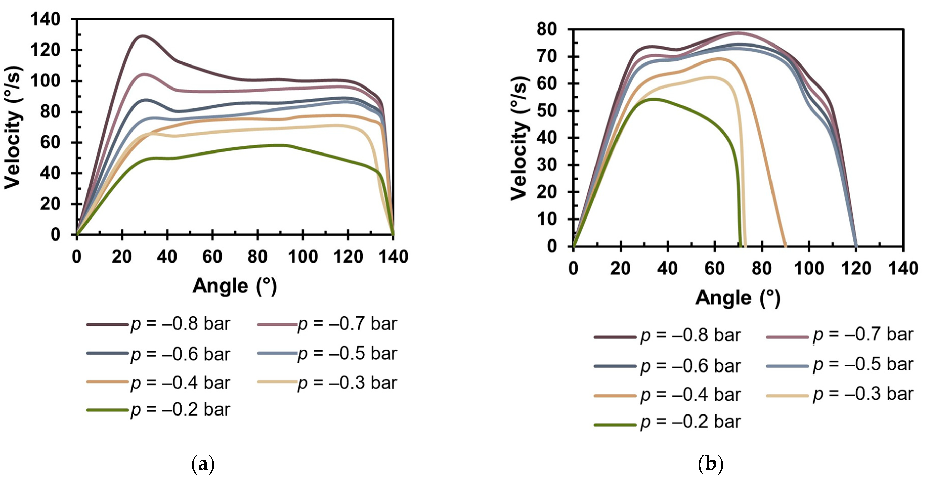
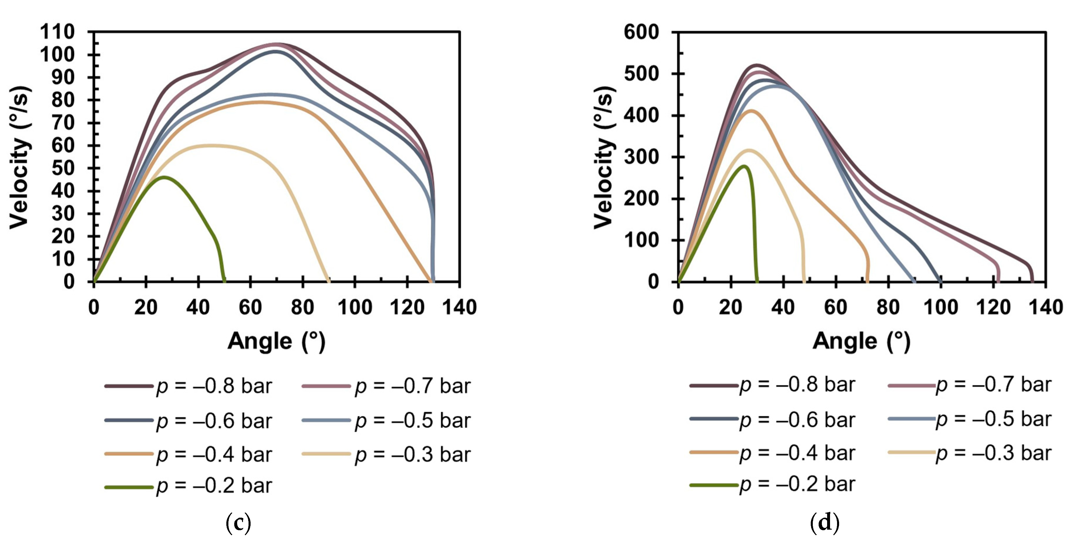
Based on the achieved bending angle–time results, the relationship between angular velocity and bending angle was calculated. From the results obtained for the VSBA-1 (Figure 7a), it is evident that the maximum velocity of ω = 130°/s is achieved at p = −0.8 bar. Analyzing the velocity dynamics for all vacuum pressures reveals a sharp increase in velocity until it reaches its peak, after which the velocity gradually decreases as the VSBA-1 bends to its final position. For vacuum pressures ranging from −0.5 bar to −0.8 bar, the maximum velocities are achieved at an angle of θ = 30°, while for lower vacuum values, the maximum velocities are reached within an angle range of 80° to 120°. Additionally, it has been demonstrated that angular velocity and bending angle are linearly dependent up to an angle of θ = 25°, indicating that airflow and the actuator surface are also linearly dependent within this range of angles. The results of angular velocity–bending angle characteristics with a 0.5 kg load (Figure S2a in the Supplementary Materials) show a similar dynamic behavior, though lower velocity values were achieved. At p = −0.8 bar, the maximum velocity is ω = 68°/s, which is 48% lower compared to the case without a load.
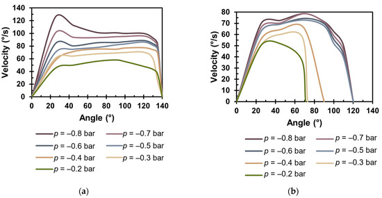
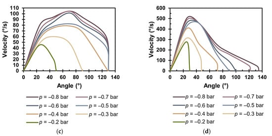
Figure 7.
Angular velocity–bending angle characteristic without load: (a) VSBA-1; (b) VSBA-2; (c) VSBA-3; (d) VSBA-4.
Analyzing the angular velocity results of the VSBA-2 (Figure 7b) reveals a different operating dynamic compared to the VSBA-1. The angular velocity increases up to 92% of its maximum value, then decreases, and increases again until it reaches its maximum value. The maximum velocity is achieved within the angular range of 60° to 80° and amounts to ω = 79 °/s at p = −0.8 bar, which is 40% lower compared to the VSBA-1. The angular velocity–bending angle results with a 0.5 kg load (Figure S2b in the Supplementary Materials) show the same dynamics, with a maximum velocity of ω = 38°/s at p = −0.8 bar, which is 52% lower than the unloaded case. It was also confirmed that angular velocity and bending angle are linearly dependent up to a θ = 20°. The angular velocity results for the VSBA-3, shown in Figure 7c, indicate that the VSBA-3 achieves a higher maximum velocity compared to the VSBA-2. A maximum velocity of ω = 104°/s is achieved at p = −0.8 bar, which is 25% higher. This further confirms that increasing the spacing between ribs enhances the actuator’s performance. The angular velocity results with a load (Figure S2c in the Supplementary Materials) show the same dynamics, with a maximum velocity of ω = 52°/s at p = −0.8 bar, which is 50% lower compared to the unloaded case.
The results for the VSBA-4, shown in Figure 7d, demonstrate a significantly higher maximum velocity compared to previous VSBAs. A maximum angular velocity of ω = 520 °/s was achieved at p = −0.8 bar and θ = 30°. These results indicate that reducing the actuator’s surface area exposed to airflow increases velocity, consistent with the continuity equation. The results of angular velocity over bending angle with a 0.1 kg load (Figure S2d in the Supplementary Materials) confirm the same dynamic, with a maximum velocity of ω = 270°/s at p = −0.8 bar, which is about 48% lower than the velocity in the unloaded case. Additionally, it was demonstrated that the angular velocity and angle are linearly dependent up to an angle of 20° for both, with or without the case.
4. Vacuum-Driven Soft Robotic Gripper Assembly
The previous experimental assessments confirmed the outstanding performance of the developed novel VSBA. The proposed VSBA design demonstrated its capability for integration into real mechatronic systems, leading to the development of a soft robotic gripper. The robotic gripper is a sophisticated mechatronic system, typically consisting of three actuators that work together to grasp an object for subsequent manipulation. The advantages of using soft actuators in robotic grippers include the ability to adapt to objects of irregular shapes and to control the force applied by the actuators on the object. With soft pneumatic actuators, the force can be easily controlled by altering the vacuum pressure with a pressure regulator, allowing for precise control of the gripping force.
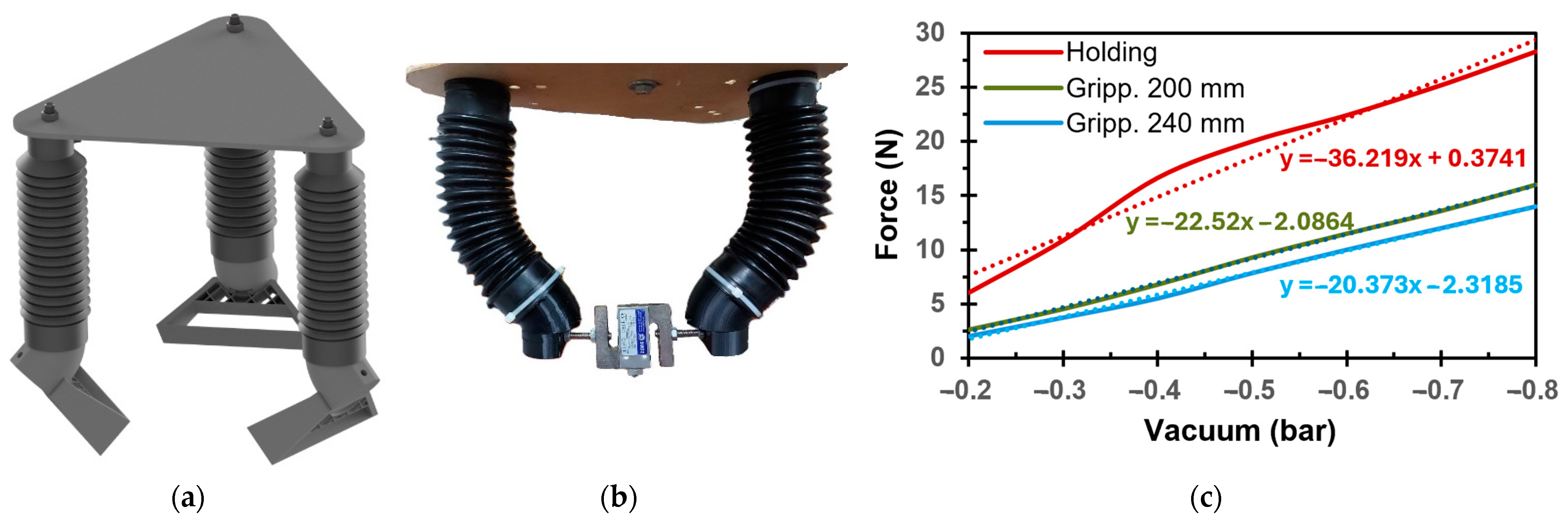
Based on the results indicating that the VSBA-1 generates the highest maximum force and achieves a bending angle of up to 140°, it was decided to incorporate three VSBA-1s into the soft robotic gripper. The design of the soft robotic gripper follows the principle of simplicity, featuring a configuration in which three actuators are evenly spaced at 120° intervals along a circular arrangement. This assembly is achieved using a triangular support plate, which has holes for mounting the actuators according to a predefined geometry, as shown in Figure 8a. The actuators are fastened to the plate with screws on the upper lid, while the lower end of the actuators allows for bending. The support plate was cut from a 4 mm thick wooden board, with the required holes drilled.
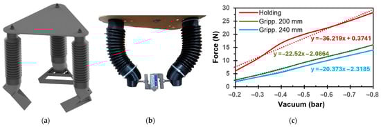
Figure 8.
Soft robotic gripper: (a) design approach; (b) experimental measurement of the gripping force; (c) results of the gripping force and holding force.
To enable soft object grasping, a grasping element was designed and mounted on the VSBA-1’s lower lid. The grasping element consists of two parts: the first part, the angular part, is fastened to the actuator’s lower lid, and is designed with a 30° inclination, allowing optimal object grasping for the VSBA-1’s dimensions. The second part, the grasping part, is mounted to the angular part and designed with a flexible surface that adapts to the shape of the object during grasping. The grasping part is primarily designed for grasping cylindrical objects but also allows for the grasping of objects with various shapes. The angular part was made using 3D printing technology with PLA material due to the requirement for strength, while the grasping part was made from TPU for flexibility requirements. The flexible surface of the gripper part allows it to adapt to the shape of the object, but the low friction between the TPU material and the object often leads to slipping. To address this issue, a thin layer of rubber was added to the flexible surface of the gripper part.
Experimental assessment of the robotic gripper includes tests of its ability to grasp objects of different shapes, as well as an analysis of the maximum gripping force and the maximum holding force. Various laboratory tests were performed, starting with an evaluation of the gripper’s ability to grasp objects with standard shapes, including cylindrical, prismatic, spherical, and similar forms. The tests confirmed the gripper’s capability to reliably grasp all tested objects, with optimal performance observed when handling cylindrical and spherical objects. For prismatic objects, there were instances where the gripper’s contact surface initially engaged an edge of the prism, causing the object to rotate until the gripper successfully grasped its flat surfaces. This rotation occurs as a result of the actuators’ capability to bend in different axes other than their primary operation axes. Such bending was observed in earlier tests on maximum blocking force (see Section 2.1). However, in the soft robotic gripper, this characteristic of the actuators proved advantageous, as it allowed the gripper to adapt to the object’s shape while grasping. Then, the gripper was tested with various objects of irregular shapes. In most cases, the gripper achieved a proper grasp, except in situations where the object’s dimensions were incompatible with the dimensions of the developed soft robotic gripper.
The next experimental assessment focused on analyzing the gripping force, defined as the force exerted by the actuators on an object, which is a critical parameter in applications involving the handling of fragile objects. To measure the gripping force, the robotic gripper was modified by removing the third actuator, leaving two actuators aligned with their operating axis. Also, the gripping parts were removed to allow the actuators to directly engage with a load cell, as illustrated in Figure 8b. Gripping an object with the robotic gripper requires a certain bending angle of the actuators. However, since previous experimental tests demonstrated a significant drop in force beyond a bending angle of 30°, all experimental measurements were conducted at bending angles up to 30°. The external dimension of the load cell, including mounting screws, was set to 80 mm. Therefore, to precisely adjust the bending angle, the spacing between the actuators was altered. This was achieved by drilling additional holes in the support plate, resulting in a first spacing of 200 mm between the actuators, and the second spacing was set at 240 mm.
The gripping force results are shown in Figure 8c. The measurements revealed that a smaller spacing of 200 mm resulted in a greater gripping force, because the bending angle of the VSBA-1 was θ = 30°. The maximum gripping force measured was F = 16 N, achieved at p = −0.8 bar. The results show that each actuator contributes approximately half of the total force (F = 8 N) applied to the gripped object. Consequently, the obtained relationship between force and vacuum pressure represents a key parameter for the precise control of gripping force using a proportional pressure control valve.
In the next experiment, the maximum holding force that the soft robotic gripper, equipped with three VSBA-1s, could apply to an object was investigated. The experiment was conducted by allowing the robotic gripper to strongly hold a cylindrical object while a pulling force was gradually applied from below, until the object slipped off the gripper’s contact surface, as shown in Figure 1f. A polypropylene rope, previously used for its resistance to stretching under load, was employed again. The rope was connected to a load cell, and weights were gradually added to generate the pulling force while data were simultaneously recorded. The outer diameter of the cylindrical object was 80 mm, and the spacing between the actuators was set to 200 mm, resulting in a bending angle of approximately 30°, as in the previous experiment. Figure 8c shows the maximum holding force as a function of vacuum pressure, with results indicating a maximum holding force of F = 28 N at p = −0.8 bar. These results demonstrate the soft robotic gripper’s capacity to strongly hold a cylindrical object with an 80 mm diameter and a mass of up to 2.8 kg and highlight the potential of the novel VSBA for integration into a soft robotic gripper.
5. Conclusions
This study presents the innovative design and manufacturing process of soft pneumatic actuators for achieving bending motion (VSBAs). The proposed design was developed to meet specific requirements, including safe operation without the risk of explosion, the ability to achieve large bending angles while generating significant forces, and the use of soft materials that are resistant to fatigue. The design of the new VSBA employs vacuum pressure and utilizes a cylindrical ribbed geometry to increase force without enlarging the actuator’s external dimensions. To enable bending, a limiting element was employed to restrict contraction on one side of the VSBA, resulting in a bending motion. Two main different actuator versions were developed, including the VSBA-1, which incorporates a commercially available ribbed bellow component made from thermoplastic rubber. Additionally, another version was designed using heat-shrinkable material, resulting in the development of an innovative manufacturing process for producing ribbed bellow components. This process allows for the fabrication of actuators in a variety of sizes and shapes. Based on this, the following actuators were developed: the VSBA-2 (maintaining the same dimensions as the VSBA-1), the VSBA-3 (maintaining the outer diameter of the VSBA-2 but with increased spacing between the bellow ribs), and the VSBA-4 (with a 50% reduction in outer diameter). This approach allowed for an analysis of the impact of actuator geometry on performance.
Experimental assessments were conducted to evaluate the maximum bending angle, maximum blocking force, and the angular velocity–bending angle characteristic. The results showed that the VSBA-1 achieved a maximum bending angle of θ = 140°, the VSBA-2 reached θ = 120°, the VSBA-3 achieved θ = 130°, and the VSBA-4 reached θ = 135°. The results show that the novel design allows significant bending angle, though actuators made from heat-shrinkable material had slightly reduced angles due to increased material stiffness. Furthermore, it was demonstrated that increasing the spacing between the bellow ribs by 50% resulted in a 10% increase in bending angle. The maximum blocking force was F = 108 N for the VSBA-1 and F = 50 N for the VSBA-2, a 65% reduction due to slightly smaller dimensions and higher resistance force resulting from increased material stiffness. The VSBA-3 achieved a maximum blocking force of F = 46 N, slightly lower than that of the VSBA-2, due to the smaller number of bellow ribs. The VSBA-4 achieved only F = 4.6 N, as expected, due to its 50% smaller outer dimensions compared to the other VSBAs.
Based on the bending angle–time results, the angular velocity–bending angle characteristic was calculated, both with and without load. The results obtained without load show a maximum velocity of ω = 130°/s for the VSBA-1, while the VSBA-2 achieved ω = 79°/s, approximately 40% lower, due to the higher stiffness of the heat-shrinkable material. The VSBA-3 achieved ω = 104°/s, which is 25% higher than that of the VSBA-2, due to the increased spacing between the bellow ribs. The angular velocity results for the VSBA-4 exhibited a significantly higher value compared to the previous versions, reaching ω = 520°/s as a result of reducing the actuator’s surface area. Experiments with load showed similar dynamics to the unloaded tests, although the maximum velocity values were lower. Additionally, it was confirmed that a linear relationship exists between angular velocity and bending angle up to 10–20% of the maximum angle, depending on the actuator version.
Finally, the soft robotic gripper, composed of three VSBA-1 actuators, was successfully developed. Experimental assessment was conducted to assess the gripper’s ability to grasp objects of various shapes, its maximum gripping force, and its maximum holding force. The results demonstrated the gripper’s effectiveness in strongly grasping objects with regular geometric shapes, while also showcasing its ability to handle irregularly shaped objects. However, this capability depends significantly on the compatibility of the objects with the gripper’s dimensions. The results of maximum gripping force revealed that the gripper’s optimal angular range is up to 30°, with a measured maximum force of F = 8 N exerted by a single actuator. Additionally, experimental tests confirmed that the gripper can achieve a maximum holding force of F = 28 N.
In conclusion, we can state that the newly developed VSBA achieved significant performance, especially when compared to previously developed soft bending actuators (see Table 1), whose manufacturing process cannot ensure long-term durability. Additionally, the successful implementation of the VSBA in the soft robotic gripper was demonstrated, showcasing its ability to grip objects of irregular shapes and provide precise control of the gripping force.
Supplementary Materials
The following supporting information can be downloaded at: https://www.mdpi.com/article/10.3390/app15052557/s1, Figure S1: Bending angle over time for actuators with load: (a) VSBA-1; (b) VSBA-2; (c) VSBA-3; (d) VSBA-4; Figure S2: Angular velocity–bending angle characteristics with load: (a) VSBA-1; (b) VSBA-2; (c) VSBA-3; (d) VSBA-4.
Author Contributions
Conceptualization, G.G.; methodology, G.G., T.V., L.G. and M.P.; software, T.V., L.G. and M.P.; validation, G.G., T.V., L.G. and M.P.; formal analysis, T.V., L.G. and M.P.; investigation, T.V., L.G. and M.P.; resources, G.G., T.V., L.G. and M.P.; data curation, T.V., L.G. and M.P.; writing—original draft preparation, G.G.; writing—review and editing, G.G.; visualization, G.G., T.V., L.G. and M.P.; supervision, G.G.; project administration, G.G.; funding acquisition, G.G. All authors have read and agreed to the published version of the manuscript.
Funding
The research was funded by the University of Rijeka Grants: uniri-iskusni-tehnic-23-174 and uniri-iskusni-tehnic-23-47.
Institutional Review Board Statement
Not applicable.
Informed Consent Statement
Not applicable.
Data Availability Statement
Data is contained within the article or Supplementary Materials.
Acknowledgments
We are thankful to Ervin Kamenar for carefully reading and providing comments.
Conflicts of Interest
The authors declare no conflicts of interest.
References
- Rus, D.; Tolley, M.T. Design, fabrication and control of soft robots. Nature 2015, 521, 467–475. [Google Scholar] [CrossRef]
- Pagoli, A.; Chapelle, F.; Corrales-Ramon, J.A.; Mezouar, Y.; Lapusta, Y. Review of soft fluidic actuators: Classification and materials modeling analysis. Smart Mater. Struct. 2021, 31, 013001. [Google Scholar] [CrossRef]
- Xavier, M.S.; Tawk, C.D.; Zolfagharian, A.; Pinskier, J.; Howard, D.; Young, T.; Lai, J.; Harrison, S.M.; Yong, Y.K.; Bodaghi, M.; et al. Soft pneumatic actuators: A review of design, fabrication, modeling, sensing, control and applications. IEEE Access 2022, 10, 59442–59485. [Google Scholar] [CrossRef]
- Tawk, C.; Alici, G. A review of 3D-printable soft pneumatic actuators and sensors: Research challenges and opportunities. Adv. Intell. Syst. 2021, 3, 2000223. [Google Scholar] [CrossRef]
- Peng, Z.; Huang, J. Soft rehabilitation and nursing-care robots: A review and future outlook. Appl. Sci. 2019, 9, 3102. [Google Scholar] [CrossRef]
- Fatahillah, M.; Oh, N.; Rodrigue, H. A novel soft bending actuator using combined positive and negative pressures. Front. Bioeng. Biotechnol. 2020, 8, 472. [Google Scholar] [CrossRef] [PubMed]
- Li, H.; Yao, J.; Zhou, P.; Chen, X.; Xu, Y.; Zhao, Y. High-force soft pneumatic actuators based on novel casting method for robotic applications. Sens. Actuators A Phys. 2020, 306, 111957. [Google Scholar] [CrossRef]
- Gariya, N.; Kumar, P.; Singh, T. Experimental study on a bending type soft pneumatic actuator for minimizing the ballooning using chamber-reinforcement. Heliyon 2023, 9, e14898. [Google Scholar] [CrossRef] [PubMed]
- Walker, S.; Rueben, J.; Volkenburg, T.V.; Hemleben, S.; Grimm, C.; Simonsen, J.; Mengüç, Y. Using an environmentally benign and degradable elastomer in soft robotics. Int. J. Intell. Robot. Appl. 2017, 1, 124–142. [Google Scholar] [CrossRef]
- Libby, J.; Somwanshi, A.A.; Stancati, F.; Tyagi, G.; Patel, A.; Bhatt, N.; Rizzo, J.; Atashzar, S.F. What Happens When Pneu-Net Soft Robotic Actuators Get Fatigued? In Proceedings of the 2023 International Symposium on Medical Robotics (ISMR), Atlanta, GA, USA, 19–21 April 2023; pp. 1–6. [Google Scholar] [CrossRef]
- Li, S.; Vogt, D.M.; Rus, D.; Wood, R.J. Fluid-driven origami-inspired artificial muscles. Proc. Natl. Acad. Sci. USA 2017, 114, 13132–13137. [Google Scholar] [CrossRef]
- Felt, W.; Robertson, M.A.; Paik, J. Modeling vacuum bellows soft pneumatic actuators with optimal mechanical performance. In Proceedings of the 2018 IEEE International Conference on Soft Robotics (RoboSoft), Livorno, Italy, 24–28 April 2018; pp. 534–540. [Google Scholar] [CrossRef]
- Xu, Q.; Zhang, K.; Ying, C.; Xie, H.; Chen, J.; E, S. Origami-Inspired Vacuum-Actuated Foldable Actuator Enabled Biomimetic Worm-like Soft Crawling Robot. Biomimetics 2024, 9, 541. [Google Scholar] [CrossRef] [PubMed]
- Kanno, T.; Ohkura, S.; Azami, O.; Miyazaki, T.; Kawase, T.; Kawashima, K. Model of a coil-reinforced cylindrical soft actuator. Appl. Sci. 2019, 9, 2109. [Google Scholar] [CrossRef]
- Sugimoto, Y.; Naniwa, K.; Nakanishi, D.; Osuka, K. Length control of a McKibben pneumatic actuator using a dynamic quantizer. Robomech J. 2024, 11, 8. [Google Scholar] [CrossRef]
- Qiu, Z.; Zhang, S.; Xue, Y.; Zhang, Y.; Mori, Y.; Hirai, S.; Kawamura, S.; Wang, Z. An empirical model of soft bellows actuator. Sci. Rep. 2024, 14, 28681. [Google Scholar] [CrossRef] [PubMed]
- Lee, J.G.; Rodrigue, H. Origami-based vacuum pneumatic artificial muscles with large contraction ratios. Soft Robot. 2019, 6, 109–117. [Google Scholar] [CrossRef]
- Tang, X.; Li, H.; Ma, T.; Yang, Y.; Luo, J.; Wang, H.; Jiang, P. A review of soft actuator motion: Actuation, design, manufacturing and applications. Actuators 2022, 11, 331. [Google Scholar] [CrossRef]
- Su, M.; Xie, R.; Zhang, Y.; Kang, X.; Huang, D.; Guan, Y.; Zhu, H. Pneumatic soft actuator with anisotropic soft and rigid restraints for pure in-plane bending motion. Appl. Sci. 2019, 9, 2999. [Google Scholar] [CrossRef]
- Liu, Z.; Wang, F.; Liu, S.; Tian, Y.; Zhang, D. Modeling and analysis of soft pneumatic network bending actuators. IEEE/ASME Trans. Mechatron. 2020, 26, 2195–2203. [Google Scholar] [CrossRef]
- Taguchi, R.; Sawada, Y. Design and grasping control of rib-reinforced bending soft actuators by vacuum driven. In Proceedings of the 2021 21st International Conference on Control, Automation and Systems (ICCAS), Jeju, Republic of Korea, 12–15 October 2021; pp. 406–411. [Google Scholar]
- Xiao, W.; Xie, C.; Xiao, Y.; Tang, K.; Wang, Z.; Hu, D.; Ding, R.; Jiao, Z. A new vacuum-powered soft bending actuator with programmable variable curvatures. Mater. Des. 2025, 250, 113641. [Google Scholar] [CrossRef]
- Himaruwan, S.; Tennakoon, C.L.; Kulasekera, A.L. Development and characterization of an origami-based vacuum-driven bending actuator for soft gripping. In Proceedings of the 2023 IEEE International Conference on Soft Robotics (RoboSoft), Singapore, 3–7 April 2023; pp. 1–6. [Google Scholar]
- Tomori, H.; Hiyoshi, K.; Kimura, S.; Ishiguri, N.; Iwata, T. A self-deformation robot design incorporating bending-type pneumatic artificial muscles. Technologies 2019, 7, 51. [Google Scholar] [CrossRef]
- Zhu, Y.; Wang, T.; Gong, W.; Feng, K.; Wang, X.; Xi, S. Design and motion analysis of soft robotic arm with pneumatic-network structure. Smart Mater. Struct. 2024, 33, 095038. [Google Scholar] [CrossRef]
- Sut, D.J.; Sethuramalingam, P. Design optimisation and an experimental assessment of soft actuator for robotic grasping. Int. J. Intell. Robot. Appl. 2024, 8, 758–786. [Google Scholar] [CrossRef]
- Lei, J.; Ge, Z.; Fan, P.; Zou, W.; Jiang, T.; Dong, L. Design and manufacture of a flexible pneumatic soft gripper. Appl. Sci. 2022, 12, 6306. [Google Scholar] [CrossRef]
- Xiao, W.; Hu, D.; Chen, W.; Yang, G.; Han, X. Design, characterization and optimization of multi-directional bending pneumatic artificial muscles. J. Bionic Eng. 2021, 18, 1358–1368. [Google Scholar] [CrossRef]
- Lv, Z.; Hao, W.; Xiao, F.; Chen, P.; Liu, Z.; Wang, Y. Soft pneumatic actuator from particle reinforced silicone rubber: Simulation and experiments. J. Appl. Polym. Sci. 2022, 139, e52795. [Google Scholar] [CrossRef]
- Lu, Y.; Tong, L. Optimal design and experimental validation of 3D printed soft pneumatic actuators. Smart Mater. Struct. 2022, 31, 115010. [Google Scholar] [CrossRef]
- Torzini, L.; Puggelli, L.; Volpe, Y.; Governi, L.; Buonamici, F. Characterization of fatigue behavior of 3D printed pneumatic fluidic elastomer actuators. Int. J. Adv. Manuf. Technol. 2024, 134, 2725–2736. [Google Scholar] [CrossRef]
- Gregov, G.; Ploh, T.; Kamenar, E. Design, development and experimental assessment of a cost-effective bellow pneumatic actuator. Actuators 2022, 11, 170. [Google Scholar] [CrossRef]
- Tanaka, J.; Ogawa, A.; Nakamoto, H.; Sonoura, T.; Eto, H. Suction pad unit using a bellows pneumatic actuator as a support mechanism for an end effector of depalletizing robots. ROBOMECH J. 2020, 7, 2. [Google Scholar] [CrossRef]
- Zaghloul, A.; Bone, G.M. Origami-inspired soft pneumatic actuators: Generalization and design optimization. Actuators 2023, 12, 72. [Google Scholar] [CrossRef]
- Gregov, G.; Pincin, S.; Šoljić, A.; Kamenar, E. Position Control of a Cost-Effective Bellow Pneumatic Actuator Using an LQR Approach. Actuators 2023, 12, 73. [Google Scholar] [CrossRef]
Disclaimer/Publisher’s Note: The statements, opinions and data contained in all publications are solely those of the individual author(s) and contributor(s) and not of MDPI and/or the editor(s). MDPI and/or the editor(s) disclaim responsibility for any injury to people or property resulting from any ideas, methods, instructions or products referred to in the content. |
© 2025 by the authors. Licensee MDPI, Basel, Switzerland. This article is an open access article distributed under the terms and conditions of the Creative Commons Attribution (CC BY) license (https://creativecommons.org/licenses/by/4.0/).