Article

Assist-as-Needed Controller of a Rehabilitation Exoskeleton for Upper-Limb Natural Movements

1
State Key Laboratory of Robotics and System, Harbin Institute of Technology, Harbin 150001, China
2
Department of Naval Architecture and Ocean Engineering, Harbin Institute of Technology (Weihai), Weihai 264209, China
3
Robot Division, Beijing Research Institute of Automation for Machinery Industry Co., Ltd., Beijing 100120, China
4
Robot Division, Shandong Guoxing Smartech Co., Ltd., Yantai 250100, China
5
Beijing Institute of Space Mechanics and Electricity, China Aerospace Science and Technology Corporation, Beijing 100190, China
*
Authors to whom correspondence should be addressed.
Appl. Sci. 2025, 15(5), 2644; https://doi.org/10.3390/app15052644
Submission received: 28 January 2025 / Revised: 14 February 2025 / Accepted: 26 February 2025 / Published: 28 February 2025
(This article belongs to the Special Issue Emerging Technologies for Assistive Robotics)

Abstract

:
Active patient participation in the rehabilitation process after stroke has been shown to accelerate neural remodeling. The control framework of rehabilitation robots should provide appropriate assistive forces to users. An assist-as-needed (AAN) control method is proposed to help users to move upper limbs in the workspace freely, and to control the exoskeleton to provide assistance. The method is based on zero moment control (ZMC), helping the user achieve robotic traction with minimal interaction force. Based on the posture of the upper arm and forearm, an AAN controller can modify assistive forces at two human–robot-interaction (HRI) points along the direction opposite to gravity. A shoulder motion prediction model is proposed to enable the exoskeleton to mimic the user’s upper limb natural movements. In order to improve the transparency during rehabilitation training, a nonlinear numerical friction model based on the Stribeck friction model is developed. A healthy adult male was recruited to perform various activities of daily living (ADL) tests to assess the effectiveness of the controllers. The experimental results show that the proposed ZMC controller has high HRI transparency and can control the exoskeleton to complete a wide range of upper limb movements, and the maximum interaction force and torque can be captured within −7.76 N and 4.58 Nm, respectively. The AAN controller can provide appropriate assistance in the desired direction, and the exoskeleton maintains kinematic synchronization with the user’s shoulder during shoulder girdle movement.

1. Introduction

Stroke is a widespread and severe health issue globally, being one of the leading causes of adult disability. Based on 2016 data, global stroke incidence reached 13.7 million cases across 22 categories, with a persistent upward trend in these figures [1,2]. The aftereffects of stroke differ from person to person, with motor dysfunction being the most frequently observed and widely recognized impairment [3,4]. This severely affects a patient’s daily activities and independence. Many patients did not receive timely rehabilitation due to a shortage of therapists and the heavy burden on healthcare systems. As a result, there is a growing need for safe, effective, and automated rehabilitation solutions to address this demand under limited resources. Compared to traditional manual therapy, robot-assisted therapy offers significant advantages, including the ability to provide repetitive treatments and real-time feedback. In recent years, rehabilitation robots for upper limb paralysis following stroke have made significant progress. The research has demonstrated that these robots effectively enhance motor control, muscle strength, and neural remodeling while maintaining high levels of safety and feasibility [5,6,7,8,9].
Exoskeletons have achieved good results in providing repetitive motion assistance to help patients. However, there are challenges in understanding the user’s movement intentions and working with the user to accomplish rehabilitation. Two mainstream methods of identifying user intention is based on biological signals and based on interactive force signals. The human brain plans limb movements, and then neurons release neurotransmitters to generate a potential difference, which stimulates muscle contraction to complete the action. Therefore, biological signals have feedforward characteristics.
EMG signals infer movement intention by detecting the electrical activity of muscles. Electrical signals collected by the non-invasive electrodes can be used to estimate the strength and frequency of muscle contractions and infer the user’s movement intentions. Some studies have established relationship between robot-assisted systems and EMG signals by constructing linear and nonlinear physical models [10,11,12]. The myoelectrically driven Hill-type musculoskeletal model, as an anatomical nonlinear physical model, is widely used to reflect the dynamic changes in the muscle and skeletal system and is considered to have high accuracy in simulating and predicting muscle activity [13]. These models can effectively convert EMG signals into control instructions, thereby achieving precise regulation of robot movement. EEG signals directly reflect the electrical activity of the cerebral cortex. Several control methods have been proposed to assist patients with severe disabilities [14,15]. EEG signals directly reflect the electrical activity of cerebral cortex, and some control methods have been proposed to assist severely disabled patients [16,17]. However, due to significant individual differences, high sensitivity to noise, and limited spatial resolution of the signals, the calibration and decoding of biological signals present challenges for robot control.
Force/torque sensors can directly detect human–robot-interaction (HRI) forces, providing a natural and intuitive feedback mechanism. These sensors have extremely high accuracy, and the signals do not require a complex decoding process. Therefore, this intent recognition method has wide adaptability. Impedance control, admittance control, and virtual mass control achieve HRI through this detection method [18,19,20].
One to three months after a stroke, the brain and nervous system of a patient have high neuroplasticity, and appropriate minimal interventions can promote recovery with significant results. In this context, AAN control was proposed. This strategy aims to help patients complete tasks with as much of their own effort as possible and avoid over-reliance on the robot by precisely adjusting the robot’s assistive force. Some studies use impedance control strategies to generate guiding forces based on the deviation between user’s movement and desired trajectory. Multimodal information is integrated to dynamically adjust the impedance parameters, which helps encourage collaboration between the user and the robot [21,22]. An optimal impedance control scheme based on model predictive control is proposed to regulate the robot’s stiffness [23]. It increases the load on the subject’s joint muscles, thereby enhancing the subject’s active participation. Another approach is the velocity field-based controller. This method requires defining proximal and distal regions in advance [24,25]. When the user’s hand is in the proximal region, a velocity field can be used to guide the subject. In the distal region, a normal force field is applied to prevent large deviations. The velocity vector is determined solely by the hand’s position, so there is no need to plan the position beforehand. A virtual tunnel-based strategy corrects the user’s motion by creating a virtual tunnel or motion space using force and visual feedback [26,27]. If the user moves close to or beyond the tunnel boundaries, the robot guides the user along the normal of the surface. However, the existing methods require pre-planning trajectories or dividing regions. There is a lack of a strategy that allows users to move freely with the robot still providing appropriate assistance.
Compared with the existing methods, the main contribution of this work is a novel AAN control framework. This framework can control the exoskeleton to provide appropriate assistance to upper limbs against gravity according to the postures of the upper arm and forearm, while following the user’s active intent during motion. The controller developed in this work is based on ZMC, which minimizes human–robot interaction force by utilizing joint torque feedback and the exoskeleton’s dynamic model. To reduce the impact of joint frictional torque and improve the exoskeleton’s response to external forces at low velocity, a multi-segment nonlinear friction model is established. Additionally, an assistive force compensation based on the upper limb’s motion state and a shoulder motion prediction model are incorporated into the framework, enabling the exoskeleton to replicate the natural movement of the user’s upper limb while providing varying levels of assistance.
The remainder of this paper is organized as follows: Section 2 describes the hardware design and control system of the upper limb exoskeleton. Section 3 presents the details of the proposed control algorithm. Section 4 provides experimental results that validate the effectiveness of joint response and control strategy. Finally, Section 5 concludes this paper.

2. Materials and Methods
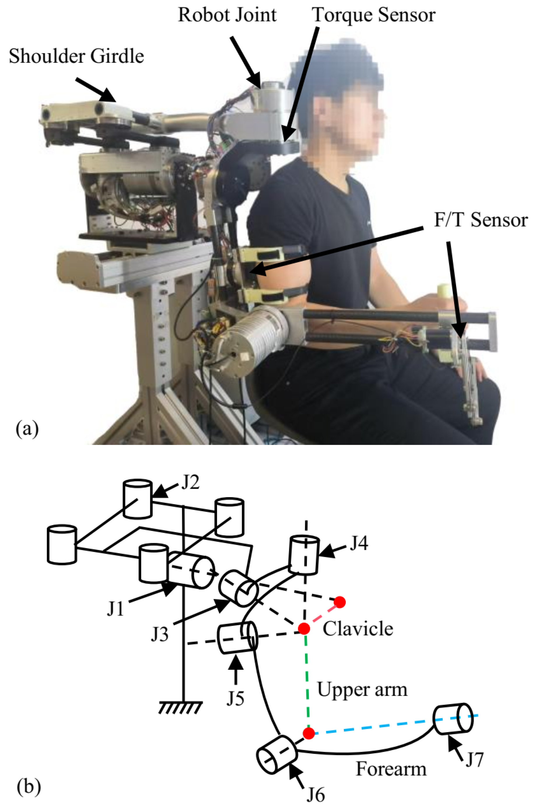
2.1. System Design

FREE is a 7-DOF exoskeleton with closed chains. FREE is composed of a parallelogram shoulder girdle (2-DOF), a shoulder joint (3-DOF), an elbow joint (1-DOF), and a wrist joint (1-DOF), as shown in Figure 1. In previous studies, structural parameters were optimized based on metrics such as ROM, the Jacobian condition number, and exoskeleton volume [28]. FREE offers sufficient mobility and can safely assist users in performing most ADLs. A visualization method is proposed to describe three consecutive rotations in a two-dimensional plane. This method is used to represent the three consecutive rotations of the human shoulder joint. It utilizes the Mollweide projection to map the spherical surface onto a two-dimensional plane, similar to a flat map of the earth. The Mollweide projection is preferred over the equalrectangular projection due to its avoidance of distortion at the poles and aesthetic characteristics. This method is used to represent the range of motion of the shoulder ball-and-socket joint, as shown in Figure 2.
Each joint of the FREE is equipped with a Maxon EC frameless motor, a harmonic drive gear, and a joint torque sensor. The detailed parameters of each joint are provided in Table 1. Each torque sensor has a resolution of 0.008 Nm. As shown in Figure 1, there are two physical interaction points between FREE and user: one at the user’s hand and end-effector of FREE, the other at the user’s upper arm and link 5 of FREE. A 6-axis Force/Torque sensor (Sunrise, M3712A/M3714A) is installed at each interaction point to measure interaction torques. These sensors provide force and torque measurements within a range of ±400 N and ±22 Nm in the xy-plane and ±800 N and ±22 Nm in the z-direction, with noise levels under 0.02%.
Upper-level controller is designed based on the embedded Beckhoff industry computer. To satisfy the high efficiency and real-time requirements, the communication between the controller and servo system is designed based on the EtherCAT protocol. The exoskeleton has an emergency stop button to deal with unforeseen situations. The frequency of the control algorithm is 1000 Hz.
The AAN controller is based on the ZMC. In the ZMC, the gravitational and frictional torques of the exoskeleton are compensated in the feedforward path. This enables the user to apply only minimal force to reverse-drive FREE. Building upon this, the AAN provides appropriate assistance based on the user’s movement intent and upper limb posture.

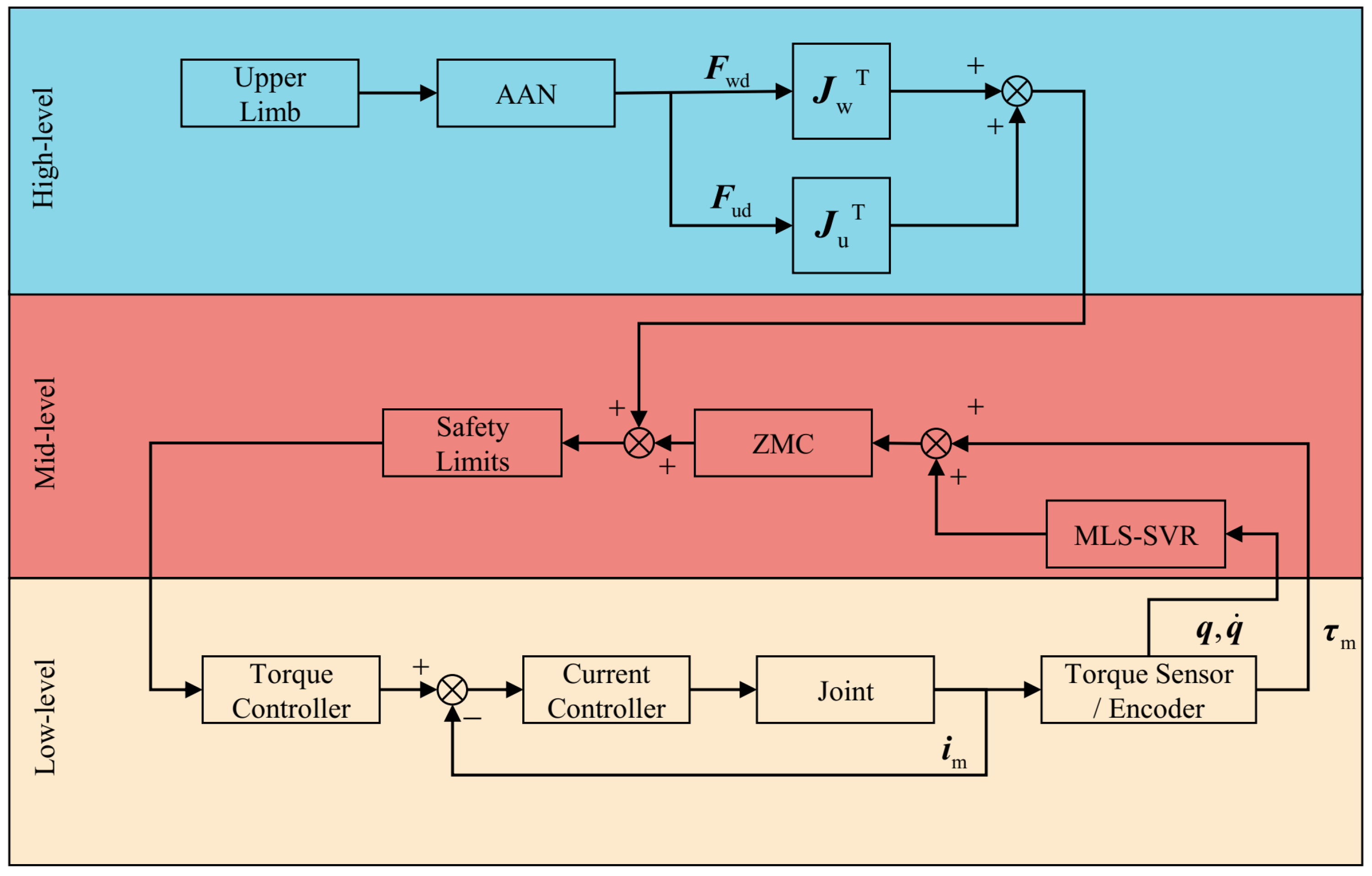
2.2. Zero Moment Control

Dragging teaching is a direct, interaction-based teaching method. The operator applies a small force to guide the robot in task performance. ZMC can achieve this function. The controller must meet the following requirements to fulfill the needs of both users and therapists:
  • Robot control based on dynamic models involves two types of feedback: measuring current and measuring torque. Current signal contains significant high-frequency noise, making it difficult to extract accurate raw signals. Additionally, the precision of calculating joint friction through current measurements is not ideal. Each joint of FREE is equipped with a torque sensor and can be used for the detection of torque applied to joint. The measured signals include inertial torque, centripetal torque, Coriolis torque, gravitational torque, frictional torque, and HRI torque. Therefore, ZMC must compensate for the influence of other torques and assist the user to achieve robot traction with minimal interaction force.
  • After the user moves FREE to a desired pose, it is essential to ensure that FREE remains stationary under the influence of gravity. When the user does not apply any force to the exoskeleton, FREE is capable of compensating for its own weight and remaining stationary.
  • FREE has comprehensive force sensing capabilities. Its force sensing area is not limited to the above two interaction points. FREE can detect interaction forces applied by the user at any point on itself and respond according to the user’s intent.
Each joint of the FREE exoskeleton is equipped with a harmonic drive gear. The Flexspline of the harmonic drive gear is designed as a thin-walled cylindrical structure that undergoes elastic deformation under load during operation. The joint torque sensor includes an inner ring and an outer ring, and it calculates torque based on the strain signals generated by strain gauges. Therefore, each joint exhibits elasticity, and the flexible components such as the harmonic drive gears and torque sensor can be equivalent to a spring with K as the equivalent stiffness coefficient. It calculates torque based on the strain signals generated by strain gauges. Each joint exhibits elasticity and rotor inertia and can be modeled as a second-order system [29], as follows:
M ( q ) q ¨ + C ( q , q ˙ ) q ˙ + g ( q ) = τ s + τ ext τ s = K ( θ q ) B θ ¨ + τ s = τ m τ fri
The flexible components, such as harmonic drive gears and torque sensor, can be equivalent to a spring, where K R n × n is the equivalent stiffness coefficient, and B R n × n is the motor rotor’s inertia. τ m R n represents the motor’s output torque, τ fri R n is joint frictional torque, θ R n is the motor rotor’s angle, q R n is the gear’s angle, and τ s R n is the torque at the output link, which is also measured by the torque sensor. τ ext represents the HRI torque, while M ( q ) R n × n , C ( q , q ˙ ) R n × n , and g ( q ) R n denote the robot’s inertial matrix, Coriolis matrix, and gravity vector, respectively.
By analyzing (1), it can be observed that the dynamics model of the flexible joint’s load exhibits nonlinear and strongly coupled characteristics. In low-velocity motion conditions, the load is primarily influenced by the gravity term g ( q ) on the link side. Therefore, the core task of ZMC is to accurately distinguish the external torque applied by the user from the robot’s gravitational and frictional torques, ensuring the joint motor responds solely to the user’s external torque.
During the process of co-movement, the user wishes to move the robot by applying minimal torque. A controller needs to be designed to compensate for gravitational torque and joint frictional torque. The controller can be designed as follows:
τ m = τ s + K t ( g ( q ) τ ) + τ fri
where K t R n × n is the compensation gain. Combining (1) and (2) gives (3):
τ ext = M ( q ) q ¨ + C ( q , q ˙ ) q ˙ + K t 1 B θ ¨
The controller in (2) compensates for the gravitational and frictional torques of FREE. As K t increases, rotor inertia decreases significantly. However, due to errors in the dynamic model, excessively large values of K t may result in torque saturation and cause mechanical vibrations. The velocity on each axis typically does not exceed 100 ° /s during the teaching process; therefore, torques generated by M and C are also at low levels. Equation (3) indicates that the user only needs to apply minimal torque to guide the movement of FREE.

2.3. Friction Modeling

Compensating for joint friction has a significant effect on interaction transparency. Joint friction can be modeled by measuring the torque required to rotate the motor at different velocities. For BLDC, output torque is linearly proportional to the current. When the motor is unloaded and only affected by frictional forces, the motor torque τ fri can be obtained using the motor’s torque constant, as follows:
τ fri = N m K m I m
where N m , K m , and I m denote the gear ratio of each joint, feedback current, and torque coefficient of the motors, respectively.
The first term on the right side of the equation is a function related to the sign of the velocity, which causes the direction of the friction torque to change suddenly when the motor velocity passes through 0. Previous studies commonly employed a friction force model that combines Coulomb friction and viscous friction, expressed as
τ fri = c sgn ( q ˙ i ) + v q ˙ i
Because of the similarity in friction characteristics among different joints, J3 is selected as a representative example. Figure 3 shows the frictional torque at different velocities. As velocity increases, the friction in the harmonic drive does not exhibit a linear relationship. It can be observed that this model does not fit the friction data well at both low and high speeds. Therefore, a friction model that couples the Stribeck effect and takes into account the nonlinear relationship between viscous friction and joint speed is modified as follows:
τ fd = f c + f s f c e q ˙ i / v s s η s + f v q ˙ i η c sgn q ˙ i
where q ˙ i represents the angular velocity of the i t h joint, f c is the Coulomb friction coefficient, f s is the maximum static friction coefficient, v s is the Stribeck velocity, η s is the shape coefficient of contact friction, which ranges from 0.5 to 2, in this study η c = 1 . f v is the viscous friction coefficient, η v is the shape coefficient for viscous friction.
The friction torque exhibits two inflection points within the velocity range of [0, 30], showing a trend of decreasing first and then increasing. Therefore, a linear function is used to describe the friction torque before the first inflection point. The piecewise model is represented as
τ fri = f c r q ˙ i + F g f c r q ˙ i g if q ˙ i q ˙ i g τ f d if q ˙ i > q ˙ i g
where f c r represents the slope in the first linear interval, F g represents the vector composed of the ordinate of the first inflection point of each joint.

2.4. AAN Control Strategy

Users with hemiplegia exhibit weakened upper limb strength, and FREE needs to provide assistance during rehabilitation training. ZMC requires a minimal interactive force to drag the exoskeleton’s movement, which is insufficient to provide assistance to the user. Therefore, we add additional assistive torques based on the ZMC to support a wide range of natural upper limb movements.
When humans eat, comb hair, or grasp objects, the weight of items in the hand typically does not exceed 1 kg, such as holding a comb, a water cup, or a toothbrush. During upper limb movement, the nervous system controls muscle contractions to counteract the torque generated by gravity. However, patients with hemiplegia have insufficient muscle strength, requiring the assistance of an exoskeleton. The human upper limb is a serial kinematic chain. The weight of the forearm and wrist is less than that of the upper limb, and they are located at the end of the kinematic chain. The muscles of the upper arm need to generate more force because they bear the weight of both the upper arm and the forearm.
The upper arm vector coincides with the first column of the R 5 0 posture matrix of FREE. When the upper arm is hanging naturally, the unit direction vector is defined as u 0 = [ 0 , 0 , 1 ] T . This posture is regarded as the initial posture of the upper arm, where the gravitational moment is zero. As the upper arm abducts in the coronal and sagittal planes, the angle γ u in Figure 4 between the upper arm and u 0 increases as
v u = R 5 0 ( 1 : 3 , 1 ) γ u = v u , u 0 v u u 0
The projection of the gravitational moment of the arm in the xy-plane continuously increases until the upper arm is parallel to the horizontal plane. The first interaction point of FREE provides assistance and adjusts the level of support based on angle γ u . The desired assistance force is expressed as
F u a = 1 1 + exp k · γ u γ p F u
where F u a is the upper arm assistance force in the world coordinate system, the steepness of S-curve is adjusted by k. γ p is the parameter for adjusting the steady-state angle. In this paper, k = 0.1 , γ p = 45 ° , and F u = 10 N. When γ u = 45 ° , F u a is half of F u . When γ u = 74 . 6 ° , F u a is 95.07% of F u . Subsequently, F u a will gradually increase and approach F u .
Forearm pronation/supination depends on the rotation of the elbow joint. When the upper arm is supported, the elbow joint becomes stable. By applying force F w perpendicular to the axis of the upper arm at the hand, effective assistance can be provided. The z-axis of the F/T sensor on the forearm is perpendicular to the upper arm axis, and F w is collinear with it. F w is expressed in the sensor coordinate system and can be transformed into the world coordinate system as follows:
F w a = R 7 0 F w
where R 7 0 is the posture transformation matrix of the wrist coordinate system relative to the base coordinate system. For a rehabilitation exoskeleton consisting of n joints, the differential forward kinematics can be written as
x ˙ = J θ ˙
where x ˙ R m is the end-effector linear and rotational velocities vector, and θ ˙ R n is the joint velocity. J R m × n is the robot Jacobian matrix.
FREE provides assistance to the upper limb at two interaction points during rehabilitation training. In other words, the user applies force at different positions. These forces will generate the following torques in the joint space:
τ u = J u T F ua 1 : 5 τ f = J f T F f 1 : 7 τ a = τ u ; O 2 × 1 + τ f
Shoulder natural movement typically involves the coordinated work of multiple joints to ensure both stability and flexibility. During upper limb movements, joints collaborate to minimize unnecessary pressure and friction. The glenohumeral joint is a ball-and-socket joint formed between the humeral head and the glenoid fossa of the scapula. It represents the relative motion between the humeral head and the glenoid during shoulder movement, particularly the coordination between humeral rotation and scapular motion. A study employed two polynomials to characterize the relationship between the humeral azimuth angle and the upward/downward, extension/flexion movements of the scapulohumeral joint, though the description remains incomplete [30]. We proposed a MIMO model based on MLS-SVR algorithm to estimate the movement angles of the shoulder girdle as follows [31]:
f ˜ ( x ) = φ ( x ) T W ˜ + b ˜ T = φ ( x ) T repmat w ˜ 0 , 1 , l + φ ( x ) T V ˜ + b ˜ T = repmat j = 1 l i = 1 n α ˜ i j K x , x i , 1 , l + l γ i = 1 n α ˜ i K x , x i + b ˜ T
where φ is a nonlinear mapping function. W ˜ R h × l , V ˜ R h × l , b ˜ R l . l is the output variable dimension, α ˜ i R l consists of Lagrange multipliers, γ is the hyper-parameter. K x , x i = exp σ x x i 2 , σ > 0 .
Let f ˜ ( x ) = [ φ ed , φ pr ] , where m represents the output variable dimensions, and n is the sample size. The multi-output regression is regarded as finding the mapping between an input matrix [ φ po , φ az ] and an output matrix [ φ ed , φ pr ] . The parameters φ po and φ az are used to represent upper arm posture. φ ed and φ pr are the predicted results, which also represent the desired angles of q 1 d and q 2 d . q d . q is replace by updating q 1 d and q 2 d in (2), and it affects the gravity term.
An AAN controller was proposed based on ZMC combining all the aforementioned. Figure 5 shows the control block diagram of FREE, and (14) gives the torque controller terms.
τ m = τ s + K t ( g ( q ) τ s ) + τ fri + τ a
We used the dynamics model of FREE and torque feedback in ZMC, with feedforward compensation for gravitational and frictional torques, allowing the exoskeleton to exhibit a weightless state. ZMC is influenced by the predicted shoulder girdle angles, which correct the angles of J1 and J2, reducing residual forces and torques between the user and FREE. AAN provided additional assistance based on the posture of the upper arm. Finally, the total output torque is constrained within a safe range to prevent undesirable torques from injuring the user.

2.5. Stability Analysis

Since the AAN continuously provides counter-gravity assistance, when the user moves away and interaction does not exist, FREE tends to move upward instead of being stationary. Therefore, the stability of the baseline ZMC controller is examined.
If a given system is represented as follows:
x ˙ = f ( x , u ) y = h ( x , u )
where f ( ) and h ( ) are nonlinear vector functions, u R m is system input, u R m is system output, and x R n is system state. If there exists a continuously differentiable and positive definite energy storage function V ( x ) satisfies
V ˙ ( x ) u T y
Then, the system is passive and can be stable at the equilibrium point. To verify passivity of the baseline controller, a energy storage function is represented as the sum of the kinematic and potential energies, as follows:
V q ( q , q ˙ , θ , θ ˙ ) = 1 2 q ˙ T M ( q ) q ˙ + 1 2 θ ˙ T K t 1 B θ ˙ + 1 2 ( θ q ) T K ( θ q )
where V g ( q ) is the potential energy of the exoskeleton.
Thus, the energy storage function and its derivative can be rewritten as
V q ( q , q ˙ , θ , θ ˙ ) = 1 2 q ˙ T M ( q ) q ˙ + V g ( q ) + 1 2 θ ˙ T K t 1 B θ ˙ + 1 2 ( θ q ) T K ( θ q ) V g ^ ( q )
V ˙ q ( q , q ˙ , θ , θ ˙ ) = q ˙ T M ( q ) q ¨ + 1 2 q ˙ T M ˙ ( q ) q ˙ + q ˙ T g ( q ) + θ ˙ T K t 1 B θ ¨ + ( θ ˙ q ˙ ) T K ( θ q ) θ ˙ T g ¯ ( θ )
where M ˙ ( q ) 2 C ( q , q ˙ ) is a skew-symmetric matrix and satisfies y T ( M ˙ ( q ) 2 C ( q , q ˙ ) ) y = 0 . The gravity item of the exoskeleton can be represented by θ as follows [32]:
g ¯ ( θ ) = g ( q )
Therefore, substituting (20) into (19) gives
V ˙ q ( q , q ˙ , θ , θ ˙ ) = q ˙ T M ( q ) q ¨ + q ˙ T C ( q , q ˙ ) q ˙ + q ˙ T g ( q ) + θ ˙ T K t 1 B θ ¨ + ( θ ˙ q ˙ ) T g ( q ) K t 1 B θ ¨ θ ˙ g ¯ ( θ ) = q ˙ T τ + τ ext θ ˙ T K t 1 B θ ¨ + ( θ ˙ q ˙ ) T τ θ ˙ g ¯ ( θ ) = q ˙ T τ + τ ext q ˙ T g ( q ) K t 1 B θ ¨ = q ˙ T τ + τ ext q ˙ T τ = q ˙ T τ ext
The above formulas result in V ˙ q q ˙ T τ ext . This inequality proves the passivity of the ZMC controller with respect to storage function. In practice, due to the error of model estimation and damping generated by the friction, the energy of the entire system is dissipated. Therefore, the system can maintain stability in a finite time.

3. Experimental Result

A preliminary study was performed involving a 30-year-old male volunteer measuring 173 cm in height and weighing 71 kg. The participant provided voluntary consent to take part in the research. The experiment was conducted with the participant’s informed consent and adhered to the protocol approved by the Declaration of Helsinki. To maintain experimental rigor and ensure result accuracy, the study utilized the joint coordinate system definitions for the shoulder, elbow, and wrist as established by the International Society of Biomechanics and the Standardization and Terminology Committee. Motion data of the volunteer’s wrist in the global coordinate system were recorded using eight Mars2H and Nokov optical motion capture systems with a sampling rate of 60 Hz, employing reflective markers as the reference sensing method.

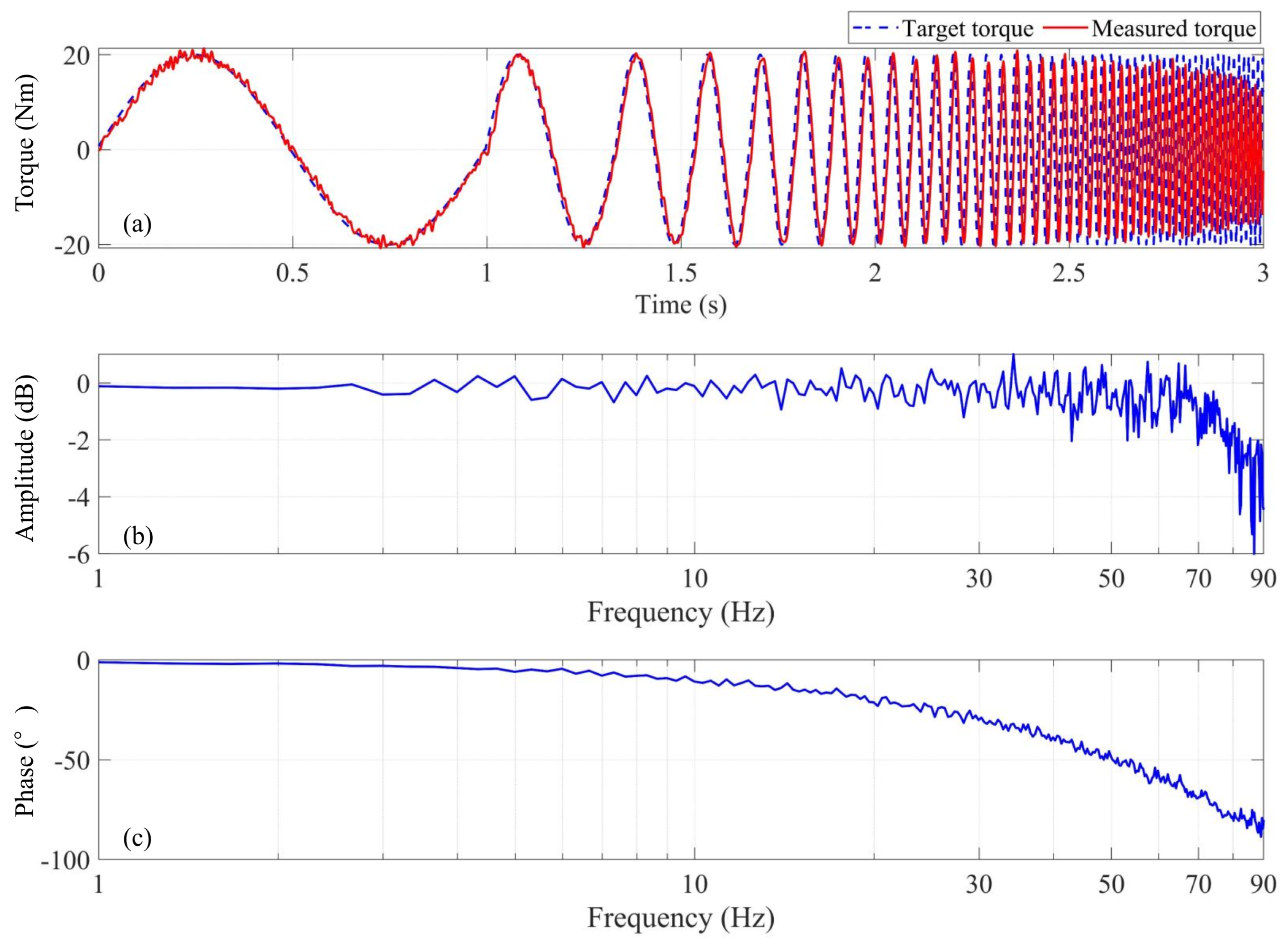
3.1. Elbow Joint Torque Response

The elbow joint is a critical component for performing ADL, the flexion and extension of the elbow is a typical movement of upper limbs. J6 is the joint on FREE that corresponds to the human elbow, and it was selected to evaluate the performance of the low level torque controller. We conducted a frequency domain analysis of the elbow joint of FREE. We tested the system’s frequency response by applying a sine wave torque input with a frequency of 1 to 90 Hz and an amplitude of 20 Nm. Figure 6a shows the time-domain joint torque response, indicating that the torque controller can accurately track the command signal. Figure 6b,c show the torque amplitude at −3 dB frequency, which is approximately 80 Hz. The torque control bandwidth of the human was found to be ≈5 Hz to 10 Hz. At 10 Hz, the torque amplitude is −0.09 dB, and the phase is −21. 5 ° . At 80 Hz, the torque amplitude is −3 dB. Therefore, the system can provide sufficient torque output within the human frequency range.

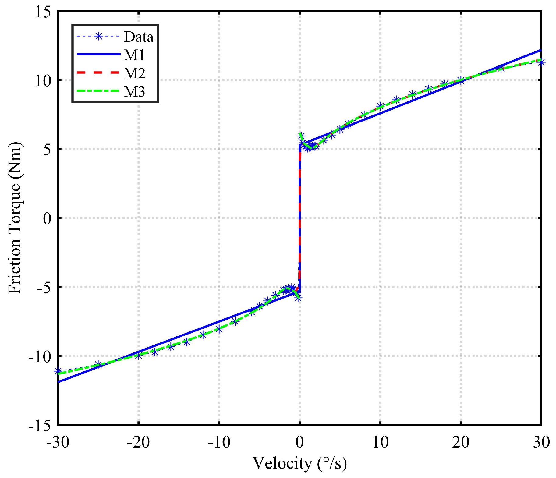
3.2. Parameter Identification of Friction Model

To simplify the measurement process, each joint was mounted on a horizontal bracket for data collection prior to exoskeleton assembly. At this stage, the joint can rotate freely without doing any work against gravity. The collected data are then used to fit the friction torque model. In this experiment, 46 joint velocities were selected to generate uniform velocity excitation trajectories, with each velocity repeated three times. To reduce signal noise, a fourth-order Butterworth low-pass filter with a cutoff frequency of 10 Hz was applied to preprocess current signals. A zero-phase filter ensured that there was no delay in filtered data. Table 2 presents a comparison between three friction models. M1, M2, and M3, corresponding to (5), (6), and (7), respectively. f represents the forward rotation of the motor, and r represents the reverse rotation of the motor.
Figure 7 shows the fitting results of three models. M1, with its linear term, cannot accurately describe joint friction at both low and high speeds. M2 improves the fitting performance at low and high speeds by modeling the Stribeck effect and the nonlinear relationship between viscous friction and speed. However, M2’s fitting curve shows two turning points at low speeds, which does not match the single extreme point of the actual friction model. Based on M2, M3 uses a linear equation to fit the data before the first extreme point of M2 and replaces the original curve, achieving better fitting results.
Table 2 shows that the M3 model consistently performs with high R 2 values under all testing conditions, particularly under the J2 test condition, where the R 2 values are 0.9994 and 0.9974, demonstrating the best fit.
R S M E is a metric used to assess the prediction accuracy of a model, with smaller values indicating less error and higher precision. Table 2 reveals that M3 performs the best in terms of RMSE, especially under the J3 test condition, where the RMSEs are 0.5211 and 0.5945, significantly lower than those of other models. Across all test conditions, the R S M E of M3 is generally lower, indicating minimal prediction error and high accuracy. Specifically, in the J3 test, the RMSE of m3 is 0.5211, which is 78.9% lower than that of M1 (2.4775) and 55.6% lower than that of M2 (1.1752). Overall, M3 consistently exhibits the lowest R S M E across all test conditions, indicating minimal prediction error and superior precision.
RSD σ ( % ) is used to measure the stability of the model results, with smaller values indicating more stable outcomes. M3 shows low RSD values under all test conditions, particularly under the J2 and J5 test conditions, where the values are 0.5681 and 0.3794, demonstrating higher stability. In the J3 data, the RSD of M3 is 1.1477, which is 21.2% of that of M1 (5.4049) and 65.9% of that of M2 (1.7412), indicating superior stability.

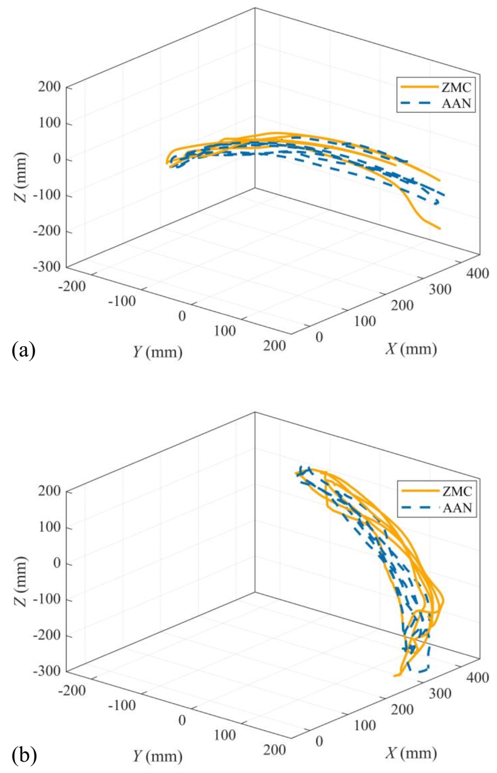
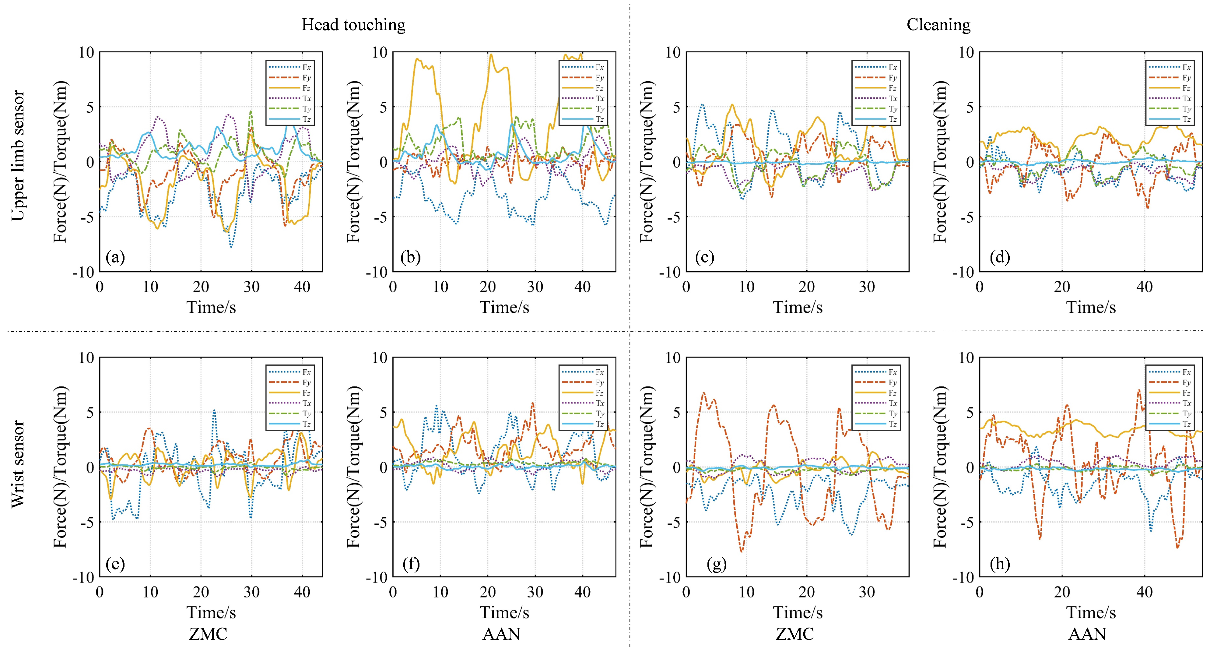
3.3. Evaluation of AAN Controller

To verify the effectiveness of the proposed controllers, we let the volunteer wear FREE for two sets of tasks. As shown in Figure 1, the volunteer’s upper limb is connected to the FREE through the upper arm attachment module and the end-effector grip. The experimental tasks include head touching and cleaning desk. During the head touching task, the volunteer is instructed to move his right hand from a specified starting point to head. In the cleaning task, two reference points are placed in front of the volunteer. He was required to control the hand to move reciprocally between these two points, while ensuring the trajectory remains as close as possible to the horizontal plane (xy-plane). In the two sets of experiments, we use the ZMC and AAN controllers to control joint torques of FREE, respectively. The trajectory of the volunteer’s right hand in two sets of tasks is shown in Figure 8. The trajectory is presented by collecting markers placed on the wrist of the volunteer using an optical motion capture system. As shown in Figure 8, after receiving the instruction to perform an action, the trajectories of the actions completed by both the volunteer and FREE under different controllers are almost identical. ZMC serves as the baseline controller for AAN. The objective of this section is to verify that the AAN can adjust the assistive torque in the intended direction based on the ZMC by using two different controllers to assist users in performing similar motions.
The data of the two F/T sensors at upper arm and forearm were converted into the base coordinate system. This can intuitively reactor the physical interaction between the volunteer and FREE. F x , F y , F z , T x , T y , and T z of each interactive point in the two groups are recorded for quantitative HRI force and torque. Figure 9 shows the complete situation of HRI force/torque in each set of experiments. Table 3 shows the average absolute value of interaction force/torque in each group of experiments.
Figure 9a,c,e,g display the active force/torque exerted by the user to drive the robot’s movement under the ZMC controller. In both task groups, the absolute values of the active forces exerted by the volunteer are all less than 8 N, and the torques are less than 5 Nm. The maximum upper limb force in the x-direction is −7.76 N (Figure 9a), and the maximum upper limb torque in the y-direction is 4.58 Nm (Figure 9a). The maximum wrist force in the y-direction is −7.71 N (Figure 9g), which corresponds to the characteristic motion of the hand primarily along the y-direction during the cleaning task. The maximum wrist torque in the x-direction is 1.11 N·m (Figure 9a). Table 3 presents the average absolute values of the interaction force/torque. The average value of the interaction force is less than 4 N, and the average torque value is less than 2 Nm. These data validate that under the ZMC controller, the user can have the FREE device follow their movement at a low interaction level.
Figure 9b,d,f,h show the interaction force/torque between the volunteer and FREE under the AAN controller. Figure 9b presents the force/torque at the upper limb interaction point during the head-touching task, displaying three distinct cycles. The yellow F z shows three rising and falling phases. Compared to the F z in Figure 9a, which remains below 0 for most of the time, F z in Figure 9b is mostly above 0. This indicates that under the ZMC controller, FREE generates some resistance while following the user’s movements. In contrast, the AAN controller provides assistance in the positive direction along the z-axis based on the volunteer’s upper arm posture. The maximum value of F z is 9.80 N, close to the expected 10 N upper limb assistance torque. During the cleaning task, γ u remains below 40°, so assistance provided by the AAN controller is limited, with the maximum value reaching 3.72 N.
Figure 9f shows assistance provided by FREE at the wrist during the head-touching task. In this task, the volunteer’s forearm moves from an initial near-horizontal posture to a near-vertical posture. Under the AAN controller, the direction of assistance at the wrist is along the z-axis of the end-effector grip, so the assistance force vector changes continuously in the world coordinate system during the movement. When the forearm is close to horizontal, F z provides the maximum assistance, with a peak value of 4.35 N. As the user’s hand approaches the head, F x provides the maximum assistance, with a peak value of 5.58 N. During the cleaning task, the user’s forearm remains close to the horizontal position; therefore, the direction of the assistance torque vector is also aligned with the z-axis. F z of Figure 9h shows that FREE provides continuous assistance to the user’s wrist, with a maximum value of 4.29 N.
Figure 10 shows the angular variation of FREE’s shoulder girdle in two tasks. In the head touching task, both q 1 and q 2 exhibit significant angular changes, with maximum variations of 11 . 31 ° and 9 . 39 ° , respectively. In the cleaning task, q 2 shows a clear periodic variation with a maximum angular change of 11 . 18 ° , while q 1 has a small variation of 3 . 25 ° . The primary reason for this is that the forearm remains close to the horizontal plane throughout this task. This results in minimal angular changes of the upper arm in the coronal plane, which has little impact on q 1 . In the experiment, FREE’s shoulder grid has the same movement trend as the volunteer’s shoulder, which verifies that the proposed shoulder prediction model allows the exoskeleton to mimic the natural movement of the human upper limb.

4. Discussion

4.1. Control Characterization

We developed a compatible AAN control framework based on joint torque feedback and a dynamic model and conducted experiments to evaluate the controller’s performance. A closed-loop torque controller was implemented for each joint, and the frequency response of the elbow joint was tested. The results showed a bandwidth of up to 80 Hz, demonstrating that FREE’s joints have excellent dynamic responsiveness and can quickly track the torque commands from the upper-level controller.
Transparency can be directly reflected through interaction forces and torques, with users experiencing minimal resistance torque while freely exploring the workspace. We emphasize the importance of achieving transparency, which is measured by the exoskeleton’s ability to avoid applying resistance or assistance during free movement. In the ZMC experiments, the average interaction force on the upper arm was 2.65 N, and the maximum average interaction force on the forearm was 3.64 N. Users only needed to apply a force equivalent to picking up an apple to guide the exoskeleton’s movement, indicating that FREE has high transparency.
Furthermore, the proposed method enables users to perform free upper limb movements within the workspace. In fact, extensive free movement is crucial when stroke patients actively explore the workspace and drive the robot. However, to our knowledge, several velocity-field-based AAN methods use planar 2-DOF robots to guide users within predefined areas, limiting the range of motion to the desktop space in front of the user. Virtual tunnel-based approaches expand the range of motion but still do not allow full workspace movement. Admittance control-based methods can achieve a similar range of motion as this study, but the robot can only follow the user’s pulling force and cannot provide variable assistance.
Finally, in terms of natural shoulder motion, different shoulder movement models have been applied in systems like Harmony, ANYexo, and CLEVERarm. However, these studies primarily focus on the exoskeleton following the user’s movements, which differs from the approach of providing assistance in this study. Additionally, due to variations among experimental subjects, shoulder motion characteristics vary significantly between individuals, and the generalization capability of existing prediction models needs improvement. More clinical trials are required to better quantify the assistance provided by exoskeletons to the shoulder.

4.2. Rehabilitation Scenarios

The proposed AAN algorithm holds significant potential in clinical rehabilitation scenarios for patients with upper limb movement impairments caused by neurological damage (such as stroke or spinal cord injury) or musculoskeletal diseases. By dynamically generating gravity-compensating forces while maintaining a natural motion trajectory, this approach enables patients to engage in active-assisted movements, reducing muscular effort. This feature is particularly valuable in early rehabilitation, as patients often struggle against gravity during shoulder abduction/flexion movements. The preserved freedom of movement helps simulate specific tasks in ADLs, such as reaching and object manipulation, which are crucial for functional recovery. Additionally, the adaptive assistance mechanism may maintain an appropriate level of challenge by providing assistance as needed, thereby promoting neural plasticity. Compared to traditional fixed-support therapies, this approach has the potential to enhance motor learning. Furthermore, the ability to adjust quantitative resistance supports personalized rehabilitation programs, tailored to each patient’s remaining motor capacity and progressive recovery stage.

4.3. Limitations and Future Works

A limitation of this study is that the experiment was conducted on only one participant, a healthy adult male. This restricts the generalizability of the results, as the sample does not account for the diversity of physical, functional, and demographic characteristics that could affect the algorithm’s effectiveness across different individuals. The lack of variability in the test group necessitates further research on more diverse samples to ensure the algorithm’s effectiveness and safety for a broader range of users, including those with disabilities or different physiological traits. The proposed assistive control algorithm is based on the assumption that the user has insufficient muscle strength to counteract gravity. We simplified the omnidirectional movement of the upper limb, with FREE providing assistance only in the Z-direction at the upper arm. In reality, rotational assistance is needed for the upper arm and forearm during spinning, which was not addressed in this study.
In future work, elderly volunteers and hemiplegic patients will be recruited to help increase the intensity of rehabilitation therapy by assisting arm movements and encouraging active participation. Additionally, more complex upper limb movement patterns will be studied. The exoskeleton’s ability to recognize user intent will be improved, and multi-directional assistance will be provided.

5. Conclusions

This paper proposed an AAN controller based on a dynamic model for a 7-DOF upper limb rehabilitation exoskeleton to provide users with rehabilitation assistance training. The controller provides appropriate assistive forces to the upper limb by moving against gravity, according to the posture of upper arm and forearm. A joint friction model is proposed to improve the control transparency for low-velocity conditions. A shoulder angle prediction model is developed integrated into the AAN controller to control FREE to follow the natural movement of the human shoulder. The experimental results demonstrate that the proposed method ensures high transparency between FREE and the user and provide appropriate assistance to the upper limb in the desired directions. The shoulder girdle of FREE remains kinematically consistent with the user’s shoulder.

Author Contributions

Conceptualization, S.P. and J.W.; methodology, S.P., J.W. and Y.Y.; software; validation, S.P. and J.W.; formal analysis, S.P.; investigation, J.G. and Y.Y.; resources, C.T. and X.L.; data curation, B.G. and X.L. and Y.Y.; writing—original draft preparation, S.P.; writing—review and editing, S.P.; visualization, S.P. and J.W.; supervision, B.G., B.G. and X.L. and Y.Y.; project administration, Y.Y.; funding acquisition, Y.Y. All authors have read and agreed to the published version of the manuscript.

Funding

This research received no external funding.

Institutional Review Board Statement

All experimental protocols and methods were approved by the Medical Ethics Committee of Harbin Institute of Technology with Ethics No: HIT-2023043 and carried out in accordance with relevant guidelines and regulations. This study confirms that informed consent was obtained from all subjects and/or their legal guardians. Approval date is 3 August 2023.

Informed Consent Statement

Informed consent was obtained from all subjects involved in the study.

Data Availability Statement

The original contributions presented in this study are included in the article. Further inquiries can be directed to the corresponding authors.

Conflicts of Interest

Authors Chenghua Tian and Xibin Li were employed by the companies Beijing Research Institute of Automation for Machinery Industry Co., Ltd. (Chenghua Tian) and Shandong Guoxing Smartech Co., Ltd. (Xibin Li). The remaining authors declare that the research was conducted in the absence of any commercial or financial relationships that could be construed as a potential conflict of interest.

Nomenclature

AAN Assist-as-needed
ADL Activities of daily living
DOF Degrees of freedom
EMG Electromyography
EEG Electroencephalography
MIMO Multiple-input-multiple-output
ROM Range of motion
RMSE Root mean square error
RSD Relative standard deviation
ZMC Zero moment control

References

  1. Adamson, J.; Beswick, A.; Ebrahim, S. Is stroke the most common cause of disability? J. Stroke Cerebrovasc. Dis. 2004, 13, 171–177. [Google Scholar] [CrossRef] [PubMed]
  2. Lindsay, M.P.; Norrving, B.; Sacco, R.L.; Brainin, M.; Hacke, W.; Martins, S.; Pandian, J.; Feigin, V. World Stroke Organization (WSO): Global stroke fact sheet 2019. Int. J. Stroke 2019, 14, 806–817. [Google Scholar] [CrossRef] [PubMed]
  3. Kwakkel, G.; Veerbeek, J.M.; van Wegen, E.E.; Wolf, S.L. Constraint-induced movement therapy after stroke. Lancet Neurol. 2015, 14, 224–234. [Google Scholar] [CrossRef] [PubMed]
  4. Sharma, B.; Phan, P.T.; Davies, J.; Hoang, T.T.; Nguyen, C.C.; Ji, A.; Zhu, K.; Nicotra, E.; Lovell, N.H.; Do, T.N. Soft Upper-Limb Wearable Robotic Devices: Technology and Applications. Adv. Intell. Syst. 2024, 6, 2400266. [Google Scholar] [CrossRef]
  5. Toedtheide, A.; Fortunic, E.P.; Kuhn, J.; Jensen, E.R.; Haddadin, S. A wearable force-sensitive and body-aware exoprosthesis for a transhumeral prosthesis socket. IEEE Trans. Robot. 2023, 39, 2203–2223. [Google Scholar] [CrossRef]
  6. Niu, B.; Yang, D.; Wang, P.; Yang, H.; Zhang, L.; Gu, Y.; Jiang, L. Virtual-force-guided intraoperative ultrasound scanning with online lesion location prediction: A phantom study. Int. J. Med. Robot. Comput. Assist. Surg. 2023, 19, e2491. [Google Scholar] [CrossRef]
  7. Liu, Y.; Liu, Y.; Han, R.; Zheng, K.; Yao, Y.; Zhong, M. Interactive Prompt-Guided Robotic Grasping for Arbitrary Objects Based on Promptable Segment Anything Model and Force-Closure Analysis. Adv. Intell. Syst. 2024, 2400404. [Google Scholar] [CrossRef]
  8. De Oliveira, A.C.; Sulzer, J.S.; Deshpande, A.D. Assessment of upper-extremity joint angles using harmony exoskeleton. IEEE Trans. Neural Syst. Rehabil. Eng. 2021, 29, 916–925. [Google Scholar] [CrossRef]
  9. Buccelli, S.; Tessari, F.; Fanin, F.; De Guglielmo, L.; Capitta, G.; Piezzo, C.; Bruschi, A.; Van Son, F.; Scarpetta, S.; Succi, A.; et al. A gravity-compensated upper-limb exoskeleton for functional rehabilitation of the shoulder complex. Appl. Sci. 2022, 12, 3364. [Google Scholar] [CrossRef]
  10. Song, R.; Tong, K.Y.; Hu, X.; Li, L. Assistive control system using continuous myoelectric signal in robot-aided arm training for patients after stroke. IEEE Trans. Neural Syst. Rehabil. Eng. 2008, 16, 371–379. [Google Scholar] [CrossRef]
  11. Yang, R.; Shen, Z.; Lyu, Y.; Zhuang, Y.; Li, L.; Song, R. Voluntary assist-as-needed controller for an ankle power-assist rehabilitation robot. IEEE Trans. Biomed. Eng. 2022, 70, 1795–1803. [Google Scholar] [CrossRef] [PubMed]
  12. Sedighi, P.; Li, X.; Tavakoli, M. Emg-based intention detection using deep learning for shared control in upper-limb assistive exoskeletons. IEEE Robot. Autom. Lett. 2023, 9, 41–48. [Google Scholar] [CrossRef]
  13. Shao, Q.; Bassett, D.N.; Manal, K.; Buchanan, T.S. An EMG-driven model to estimate muscle forces and joint moments in stroke patients. Comput. Biol. Med. 2009, 39, 1083–1088. [Google Scholar] [CrossRef] [PubMed]
  14. Bhagat, N.A.; Venkatakrishnan, A.; Abibullaev, B.; Artz, E.J.; Yozbatiran, N.; Blank, A.A.; French, J.; Karmonik, C.; Grossman, R.G.; O’Malley, M.K.; et al. Design and optimization of an EEG-based brain machine interface (BMI) to an upper-limb exoskeleton for stroke survivors. Front. Neurosci. 2016, 10, 122. [Google Scholar] [CrossRef]
  15. Nann, M.; Cordella, F.; Trigili, E.; Lauretti, C.; Bravi, M.; Miccinilli, S.; Catalan, J.M.; Badesa, F.J.; Crea, S.; Bressi, F.; et al. Restoring activities of daily living using an EEG/EOG-controlled semiautonomous and mobile whole-arm exoskeleton in chronic stroke. IEEE Syst. J. 2020, 15, 2314–2321. [Google Scholar] [CrossRef]
  16. Buerkle, A.; Eaton, W.; Lohse, N.; Bamber, T.; Ferreira, P. EEG based arm movement intention recognition towards enhanced safety in symbiotic human-robot collaboration. Robot. Comput. Integr. Manuf. 2021, 70, 102137. [Google Scholar] [CrossRef]
  17. Formaggio, E.; Masiero, S.; Bosco, A.; Izzi, F.; Piccione, F.; Del Felice, A. Quantitative EEG evaluation during robot-assisted foot movement. IEEE Trans. Neural Syst. Rehabil. Eng. 2016, 25, 1633–1640. [Google Scholar] [CrossRef]
  18. Li, X.; Liu, Y.H.; Yu, H. Iterative learning impedance control for rehabilitation robots driven by series elastic actuators. Automatica 2018, 90, 1–7. [Google Scholar] [CrossRef]
  19. Wu, Q.; Wang, X.; Chen, B.; Wu, H. Development of a minimal-intervention-based admittance control strategy for upper extremity rehabilitation exoskeleton. IEEE Trans. Syst. Man Cybern. Syst. 2017, 48, 1005–1016. [Google Scholar] [CrossRef]
  20. Zimmermann, Y.; Küçüktabak, E.B.; Farshidian, F.; Riener, R.; Hutter, M. Towards dynamic transparency: Robust interaction force tracking using multi-sensory control on an arm exoskeleton. In Proceedings of the 2020 IEEE/RSJ International Conference on Intelligent Robots and Systems (IROS), Las Vegas, NV, USA, 24 October 2020–24 January 2021; pp. 7417–7424. [Google Scholar]
  21. Naghavi, N.; Akbarzadeh, A.; Tahamipour-Z, S.M.; Kardan, I. Assist-As-Needed control of a hip exoskeleton based on a novel strength index. Robot. Auton. Syst. 2020, 134, 103667. [Google Scholar] [CrossRef]
  22. Zhang, Y.; Li, S.; Nolan, K.J.; Zanotto, D. Reinforcement learning assist-as-needed control for robot assisted gait training. In Proceedings of the 2020 8th IEEE RAS/EMBS International Conference for Biomedical Robotics and Biomechatronics (BioRob), New York, NY, USA, 29 November–1 December 2020; pp. 785–790. [Google Scholar]
  23. Dos Santos, W.M.; Siqueira, A.A. Optimal impedance via model predictive control for robot-aided rehabilitation. Control Eng. Pract. 2019, 93, 104177. [Google Scholar] [CrossRef]
  24. Fang, X.K.; Han, B.; Wang, J.H.; Liu, D.Y. Adaptive velocity field control of upper-limb rehabilitation robot. In Proceedings of the 2016 Chinese Control and Decision Conference (CCDC), Yinchuan, China, 28–30 May 2016; pp. 5438–5443. [Google Scholar]
  25. Asl, H.J.; Yamashita, M.; Narikiyo, T.; Kawanishi, M. Field-based assist-as-needed control schemes for rehabilitation robots. IEEE/ASME Trans. Mechatron. 2020, 25, 2100–2111. [Google Scholar] [CrossRef]
  26. Zhang, L.; Guo, S.; Sun, Q. Development and assist-as-needed control of an end-effector upper limb rehabilitation robot. Appl. Sci. 2020, 10, 6684. [Google Scholar] [CrossRef]
  27. Guo, Y.; Tian, Y.; Wang, H.; Han, S. Adaptive hybrid-mode assist-as-needed control of upper limb exoskeleton for rehabilitation training. Mechatronics 2024, 100, 103188. [Google Scholar] [CrossRef]
  28. Pei, S.; Wang, J.; Yang, Y.; Dong, A.; Guo, B.; Guo, J.; Yao, Y. A Human-centered kinematics design optimization of upper limb rehabilitation exoskeleton based on configuration manifold. IEEE Open J. Comput. Soc. 2024, 6, 282–293. [Google Scholar] [CrossRef]
  29. Albu-Schäffer, A.; Ott, C.; Hirzinger, G. A unified passivity-based control framework for position, torque and impedance control of flexible joint robots. Int. J. Robot. Res. 2007, 26, 23–39. [Google Scholar] [CrossRef]
  30. Zarrin, R.S.; Zeiaee, A.; Langari, R.; Buchanan, J.J.; Robson, N. Towards autonomous ergonomic upper-limb exoskeletons: A computational approach for planning a human-like path. Robot. Auton. Syst. 2021, 145, 103843. [Google Scholar] [CrossRef]
  31. Pei, S.; Wang, J.; Guo, J.; Yin, H.; Yao, Y. A Human-like Inverse Kinematics Algorithm of an Upper Limb Rehabilitation Exoskeleton. Symmetry 2023, 15, 1657. [Google Scholar] [CrossRef]
  32. Ott, C.; Albu-Schaffer, A.; Kugi, A.; Hirzinger, G. On the passivity-based impedance control of flexible joint robots. IEEE Trans. Robot. 2008, 24, 416–429. [Google Scholar] [CrossRef]
Figure 1. (a) FREE exoskeleton prototype. (b) FREE simplified model.
Applsci 15 02644 g001
Figure 2. ROM of shoulder ball-and-socket joint of a healthy adult male. The blue area represents the GH workspace.
Applsci 15 02644 g002
Figure 3. Friction torque of J3 at different velocities.
Applsci 15 02644 g003
Figure 4. The scapulohumeral joint and humerus are reduced to vectors, and the direction is described by the spherical coordinate parameter. φ ed and φ pr represent the elevation/depression inclination of the y-axis and the protraction/retraction inclination of the x-axis, respectively, around the scapulohumeral’s fixed coordinate system. φ po and φ az represent the polar and azimuthal humerus angles in the torso coordinate system. γ p represents the angle between the upper arm and u 0 .
Applsci 15 02644 g004
Figure 5. Architecture of the control system, which consists of a high level, mid level, and low level.
Applsci 15 02644 g005
Figure 6. Torque response of J6. (a) Torque tracking curve. (b) bode diagram of amplitude of torque closed-loop. (c) bode diagram of phase of torque closed-loop.
Applsci 15 02644 g006
Figure 7. Comparison of three friction models. The tested joint was J2.
Applsci 15 02644 g007
Figure 8. Trajectories of the volunteers’ hands in the Cartesian coordinate system in both experimental groups. (a) head touching. (b) cleaning. The orange solid line represents hand trajectory generated by ZMC controller, the blue dashed line represents hand trajectory generated by the AAN controller.
Applsci 15 02644 g008
Figure 9. Human–robot interaction force/torque at the two connection points of the upper limb in the world coordinate system during the head-touching and cleaning tasks. The used controller is indicated at the bottom of each column. The first row represents the upper limb interaction force/torque, and the second row represents the wrist interaction force/torque. (ad) represents upper limb sensor data during two task under two controller. (eh) represents upper limb sensor data during two task under two controller.
Applsci 15 02644 g009
Figure 10. Joint angles of J1 and J2 in two tasks. (a) head touching with AAN. (b) cleaning with AAN.
Applsci 15 02644 g010
Table 1. Component Parameters of Each Joint.
J1J2J3J4J5/6J7
Reduction Ratio161:1121:1161:1101:1121:151:1
Nominal Torque87 Nm65 Nm41 Nm35 Nm22 Nm5 Nm
Nominal Speed 54  ° /s 72  ° /s 72  ° /s 188  ° /s 150  ° /s 552  ° /s
Table 2. Results of Three Friction Parameter Model.
MetricsModelJ1J2J3J4J5
R 2 M1_f0.93720.97130.95970.98920.9114
M2_f0.99330.99940.99060.99680.9517
M3_f0.99350.99940.99820.99670.9517
M1_r0.91990.95950.95530.98270.9201
M2_r0.98600.99740.98990.99810.9083
M3_r0.99140.99740.99760.99910.9084
R M S E M1_f1.92920.93572.47750.05921.0432
M2_f0.63110.13941.17520.03200.7704
M3_f0.61970.13900.52110.03290.7699
M1_r2.09021.11222.56840.08200.9546
M2_r0.87450.28191.22240.02731.0227
M3_r0.68290.28180.59450.01821.0218
σ ( % ) M1_f7.53854.49915.40490.756419.2490
M2_f2.23340.57511.74120.35525.3526
M3_f2.17780.56811.14770.37945.2395
M1_r8.24865.49935.66721.018116.3971
M2_r2.08080.75061.88650.30896.7566
M3_r1.58450.74721.30800.24286.8118
Table 3. Average Absolute Value of Interaction Force/Torque.
TaskInteraction Point F x  (N) F y  (N) F z  (N) T x  (Nm) T y  (Nm) T z  (Nm)
Head TouchingUpper Arm2.651.562.261.581.021.13
Wrist1.921.131.801.021.080.08
CleaningUpper Arm2.031.250.980.300.130.21
Wrist2.313.640.530.570.270.10
Disclaimer/Publisher’s Note: The statements, opinions and data contained in all publications are solely those of the individual author(s) and contributor(s) and not of MDPI and/or the editor(s). MDPI and/or the editor(s) disclaim responsibility for any injury to people or property resulting from any ideas, methods, instructions or products referred to in the content.

