Abstract
This paper presents the design and experimental evaluation of a throttleable pintle-centrifugal injector system tailored for hybrid rocket engines, aimed at improving combustion efficiency and enabling precise throttling control. The novel injector system combines the principles of swirl injection and pintle-based throttling, offering fine adjustment of oxidizer flow rates to optimize combustion dynamics. Cold-flow experiments using deionized water were conducted to assess the injector’s performance across a range of flow rates and pintle strokes. Results demonstrate that the pintle stroke effectively regulates injection pressure drop and atomization characteristics, with significant improvements observed in spray cone angle and droplet size distribution. The injector system achieved a pressure drop variation ratio of 4.162 at a flow rate adjustment ratio of 6.841, indicating a strong capacity for deep throttling. These findings highlight the potential of the pintle-centrifugal injector to enhance the performance and adaptability of hybrid rocket motors, offering promising applications in modern aerospace propulsion systems.
1. Introduction
The rapid advancement of space exploration, driven by an escalating demand for satellite deployment, interplanetary missions, and maneuverable launch systems, has placed unprecedented pressure on the development of next-generation rocket propulsion technologies [1]. Among the diverse array of propulsion methods available, chemical rocket engines stand out as the most mature and widely adopted technology, underpinning the majority of operational launch vehicles today. These engines are broadly classified into liquid rocket engines, solid rocket engines, and hybrid rocket motors, distinguished by the physical states and storage methods of their propellants [2,3].
Hybrid rocket motors, characterized by their integration of a liquid oxidizer with a solid fuel grain, have emerged as a particularly promising solution, striking a unique balance between the operational simplicity and inherent safety of solid propulsion systems and the precise controllability offered by liquid systems [4]. This hybrid configuration typically features a liquid oxidizer delivery system—employing oxidizers such as hydrogen peroxide or liquid oxygen (LOX)—coupled with a thrust chamber housing solid fuel, which generates combustion dynamics distinct from those of fully liquid or solid engines. The resulting diffusion flames provide notable advantages, including ease of thrust adjustment, the ability to shut down and restart, higher propellant energy density, and enhanced stability during storage and transport [5].
Despite these compelling attributes, hybrid rocket motors encounter significant hurdles in achieving the levels of throttling precision and combustion efficiency demanded by contemporary aerospace missions, where adaptability across diverse operational profiles is paramount [6]. The efficiency of combustion in these systems is intricately tied to the injector’s design and structure, which directly influences the critical processes of oxidizer-fuel mixing and heat transfer to the solid fuel grain within the thrust chamber [7]. One approach that has gained traction for enhancing combustion performance is swirl injection, a technique that imparts rotational momentum to the oxidizer flow. Research has demonstrated its efficacy in significantly boosting regression rates, with studies reporting increases ranging from 30% to as much as 2.7 times, alongside achieving specific impulses up to 263 s at sea level [8,9]. Furthermore, swirl injectors have been shown to mitigate pressure oscillations and elevate overall combustion efficiency, offering a pathway to more stable and effective hybrid motor operation [10]. However, despite these advancements, swirl-based designs frequently fall short of delivering the deep throttling capabilities required for missions demanding a wide range of thrust levels, posing a limitation to their broader adoption [11]. In contrast, pintle injectors, which have a storied history in liquid rocket propulsion, excel in providing precise flow control and rapid response under variable thrust conditions [12]. Early innovations by TRW laid the groundwork for pintle technology, culminating in its successful application in the Apollo Lunar Module Descent Engine (LMDE), renowned for its deep throttling and instantaneous shutdown capabilities [13]. Modern developments have extended pintle applications to environmentally friendly propellant combinations such as LOX/kerosene and LOX/alcohol, as seen in engines like the TR-106, capable of delivering thrusts up to 290 tons [14,15,16].
The exploration of monopropellant injectors has further broadened the scope of injector design, particularly for hybrid propulsion systems where operational simplicity and safety are prized attributes. For instance, a dual-plate injector developed for a 50 N hydrogen peroxide monopropellant thruster demonstrated a throttling range of 24–64% with characteristic velocities spanning 81–97%, showcasing the potential for fine-tuned control in compact systems [17]. Similarly, investigations into LOX/GCH4 pintle injectors have revealed enhancements in atomization quality and flame stability, critical for efficient combustion [18,19]. Green propellant alternatives have also been pursued, with ethanol-nitromethane mixtures achieving specific impulses rivaling hydrazine, while nitromethane-based designs offer low-toxicity solutions for air turbo ramjet applications [20]. Optimization efforts with hydroxylammonium nitrate (HAN)-based injectors have yielded improved regression rates and faster response times, underscoring their adaptability to hybrid configurations [21,22,23]. Advances in additive manufacturing have enabled the fabrication of complex injector geometries, further enhancing performance [1], while numerical simulations have provided deeper insights into combustion dynamics, facilitating design refinement [24,25].
Despite these strides, the integration of pintle and swirl features into monopropellant hybrid systems remains a relatively uncharted domain, with unresolved challenges in achieving seamless synergy between throttling precision and combustion enhancement [26,27,28]. This gap underscores the need for innovative injector designs that can holistically address the multifaceted demands of hybrid propulsion, leveraging the strengths of both approaches to overcome the limitations of traditional systems.
The novelty of this study lies in the introduction of a throttleable pintle-centrifugal injection system, specifically designed for hybrid rocket motors. This new system integrates the benefits of both swirl injection and pintle injection, addressing the critical need for improved combustion efficiency and throttling control. The research investigates the performance of this hybrid injector system, focusing on its ability to control oxidizer flow rate and enhance combustion dynamics in hybrid propulsion systems. This study aims to fill this gap by exploring how the combination of swirl and pintle injectors can improve the performance of hybrid rocket motors and contribute to the development of more efficient and controllable propulsion systems for future aerospace missions.
2. Design of the Throttleable Pintle-Centrifugal Injector
Design of the Pintle-Centrifugal Injector
The throttleable pintle-centrifugal injector was designed to enhance throttling precision and combustion efficiency in hybrid rocket engines. It integrates the pintle’s deep throttling ability with centrifugal swirl injection for improved atomization. The pintle adjusts the annular slit area for variable flow rates, while tangential apertures create a swirl to enhance oxidizer mixing with solid fuel. This addresses traditional injector limitations, like poor low-flow atomization, while leveraging hybrid propulsion benefits such as safety and control. Design parameters were optimized for pressure drop, spray uniformity, and structural integrity, tailored to hybrid motor needs.
As delineated in Figure 1, the pintle-centrifugal injector is an assembly comprised of the injector panel, the injector’s upper cap, the pintle mechanism, and the dynamic sealing system. Incorporated within the pintle, beneath and central to the injector panel, are conical surfaces configured at uniform angles. The axial displacement of the pintle modulates the gap between these conical surfaces, thereby varying the cross-sectional area available for injection. This dynamic adjustment enables the regulation of the pressure differential across the injector for diverse flow rates. Furthermore, the dynamic seal serves a critical function, ensuring a hermetic interface between the pintle and the injector panel throughout the pintle’s range of motion, precluding any potential fluid leakage.
Figure 1.
Diagram of the pintle-centrifugal injector.
As delineated in Figure 2, the pivotal structural parameters of the throttleable pintle-centrifugal injector designed for empirical evaluation are systematically enumerated. Within this figure, the variable s signifies the traversal range of the pintle mechanism. The count of tangential apertures within the injection panel is denoted as N, and Dt signifies the internal diameter of these orifices. Moreover, Dinj represents the diameter at the pintle’s nadir, cooperating with the injection panel’s internal diameter Da, constitutes the annular injection slit. The pintle adjusts the annular slit, formed by the injection panel’s internal diameter (Da) and the pintle’s nadir diameter (Dinj). At a pintle stroke of s = 0 mm, the slit is closed, ideally sealed, and opens progressively as s increases. Additionally, the angular disposition of the injection channels is indicated by θ. A comprehensive tabulation of these parameters is provided in Table 1. The size and scale of our injector were constrained by the experimental capabilities of our laboratory and the requirements of a standard engine test article, leading to the selection of the current dimensions, with studies conducted to investigate the effects of varying tangential hole sizes. Furthermore, the actualized physical assembly of the throttleable pintle-centrifugal injector and the pintle apparatus is depicted in Figure 3.
Figure 2.
Construction parameters of the pintle-centrifugal injector.

Table 1.
The pintle-centrifugal injector construction parameter values.
Figure 3.
(a) Pintle-centrifugal injector assembly (b) pintle (c) bottom view of the injector.
3. Experimental Investigation on the Pintle-Centrifugal Injector
3.1. Experimental System
Experimental investigations are indispensable as a primary research tool to enable a more direct exploration of hybrid rocket motors. Hot commissioning is the primary method of studying hybrid rocket motors. The cold test of the injector is a necessary part of the effective study before the hot commissioning. The cold test enables an effective study of the pressure drop characteristics and even the atomization effect of hybrid rocket motor injectors. The throttleable pintle-centrifugal injector is originally designed to control the oxidizer injection state during a wide range of thrust ratios (flow ratios) in hybrid rocket motors. In the experimental investigation, there is a high risk of damage to the test environment and personnel, if the hydrogen peroxide solution is used as the test medium. This is why our experimental study used deionized water as an alternative working fluid. Deionized water, like highly concentrated hydrogen peroxide, is a colorless liquid at room temperature and pressure, and the use of water as an alternative is a common method used in general rocket engine injector cold tests. The focus on hydrogen peroxide in this study leverages its ambient-temperature storability and aligns with the requirements of an ongoing project in our laboratory, though oxidizers like liquid oxygen (LOX), as utilized in prior studies cited in the introduction, remain viable alternatives for hybrid propulsion.
The experimental system consists of the throttleable pintle-centrifugal injector, a motor actuator, a propellant delivery system, a measurement control system, and a high-speed imaging system.
As shown in Figure 4, the throttleable pintle-centrifugal injector actuator is primarily composed of servo motors, ball screws, a grating measurement system with a resolution of 0.001 mm, and corresponding control software (Written by LabVIEW2020). The grating measurement system, with its high resolution, plays a crucial role in precisely measuring and displaying the stroke of the pintle. This system ensures accurate displacement measurement by providing real-time feedback, allowing for fine control of the pintle position and precise monitoring of its motion throughout the injection process.

Figure 4.
The injector actuators.
The propellant delivery system is shown in Figure 5. It consists of a hand valve, safety valve, high-pressure water reservoir, pressure sensor (range: 0–2 MPa, accuracy: ±0.25% FS), pneumatic valve, mass flow meter (range: 0–600 g/s, accuracy: ±0.1% FS), buffer tank, and cavitation venturi. The cavitation venturi is the flow control element of the delivery system, which accurately controls the liquid flow in the system under defined pressure conditions. The feeding pressure, ranging from 3 MPa to 4 MPa, was supplied upstream of the controllable cavitating venturi. While the cavitating venturi’s flow rate depends on upstream pressure (3–4 MPa) to sustain cavitation, the choked throat, under sonic conditions, stabilizes the downstream pressure near the fluid’s vapor pressure, providing a consistent boundary for the injector. This isolates the injector’s performance—pressure drop and atomization—from upstream pressure variations, aligning with our focus on downstream dynamics. Under cavitation, the venturi throat maintains a stable pressure, decoupling the upstream feeding pressure from the injector’s performance, making it a non-critical parameter for the observed pressure drop and atomization results.
Figure 5.
Propellant delivery system.
The measurement control system is developed based on the LabVIEW platform and is divided into the control system and the measurement system. The control system controls the valves in the conveying system according to a set timing sequence and the measurement system is able to collect the pressure and flow parameters in the system.
The high-speed imaging system consists of a high-speed camera to capture the state of the atomized flow field of the adjustable centrifugal injector during the test. The images analyzed in the following section are taken from the high-speed camera.
3.2. Experimental Process
During the test, a constant water mass flow rate is first established using a controllable cavitating venturi. At this fixed flow rate, the pintle stroke is varied to adjust the size of the annular slit in the injection channel, while a high-speed camera records the corresponding spray images and parameters. After completing a full stroke range experiment, the flow rate is adjusted to a new fixed value, and the above procedure is repeated to obtain a series of spray images and parameters corresponding to different mass flow rates and pintle strokes. For optical camera acquisition of spray images, the extraction of the atomization cone angle was previously usually performed by direct measurement. The general approach is to visually inspect the spray boundary, determine the boundary lines on both sides of the spray, and then use a protractor to measure the angle or import the image into the image software and use the protractor in the function module to obtain the angle. This method is simple and straightforward, but highly subjective, especially when the image boundary is blurred, and can lead to large errors in the results.
In this study, the spray cone angle was extracted using the method proposed by Stephane [18]. Two straight lines were taken at different distances downstream of the injector outlet and the spray width on both lines was measured.
3.3. Results and Discussion
3.3.1. Analysis of Injection Pressure Drop
Flow tests were carried out for the throttleable pintle-centrifugal Injector 1 in the deionized water mass flow range 57.3–392.7 g/s. The pressure drop was measured using a piezoresistive pressure sensor (±0.25% FS) at pressure taps located in the fluid collecting cavity, as shown in Figure 1. This pressure governs the propellant’s exit velocity, a key metric for injector evaluation, ensuring stable injection and enhanced atomization. The injection pressure drop of the injector was adjusted by varying the pintle stroke at different mass flow rates. The relationship between the injection pressure drop and the pintle stroke at different mass flow rates is shown in Figure 6. The pressure drop measurements were recorded with a pressure sensor accurate to ±0.25% of full scale. Given the high precision of the sensor, the uncertainty in the measurements has a minimal impact on the experimental data. The accuracy of the sensor ensures that the recorded pressure drops are reliable, and the effect of measurement uncertainty on the overall results is negligible.
Figure 6.
Relationship between injection pressure drop and pintle stroke (Injector 1).
As can be seen from the figure, as the pintle stroke increases, the injection pressure drop of the adjustable centrifugal injector decreases. When the pintle stroke gradually increases from 0, the injection pressure drop decreases at a faster rate. As the pintle stroke gradually increases, the rate of reduction in the injection pressure drop slows down. When the pintle stroke increases to a certain value, the injection pressure drop tends to stabilize. The pressure drop, measured in the fluid collecting cavity upstream of the tangential holes (Dt) via a piezoresistive sensor (±0.25% FS, Figure 1), is defined as the difference between cavity pressure and ambient pressure at the injector outlet, where the medium is discharged. This drop reflects the cumulative throttling effects of the tangential holes and the annular slit (formed by Da and Dinj), which sequentially serve as the minimum cross-sectional area. When the slit area (adjusted by pintle stroke, s) is less than the total area of the tangential holes, the slit dominates the drop; when it exceeds this, the holes become the primary restriction, as evidenced by the stabilizing pressure drop at higher s values (Figure 6).
In addition, as the mass flow rate of deionized water increases, the effective range of pintle stroke control gradually increases. At a deionized water mass flow rate of 57.4 g/s, the pintle stroke is no longer able to regulate the injection pressure drop of the adjustable centrifugal injector after 0.4 mm. At a deionized water flow rate of 392.7 g/s, the pintle stroke of 1.0 mm still regulates the injection pressure drop of the adjustable centrifugal injector. At a deionized water mass flow rate of 57.4 g/s and a pintle opening of 0.072 mm, the throttleable pintle-centrifugal injector achieved an injection pressure drop of 0.0697 MPa. At a deionized water mass flow rate of 392.7 g/s and a pintle opening of 0.953 mm, the throttleable pintle-centrifugal injector achieved an injection pressure drop of 0.2901 MPa. For comparison, with a deionized water mass flow rate adjustment ratio of 6.841, the throttleable pintle-centrifugal injector achieves an injection pressure drop variation ratio of 4.162 through the adjustment of the pintle stroke. Although the 4.162 pressure drop ratio achieved at this flow rate variation does not necessarily guarantee effective atomization of the throttleable pintle-centrifugal injector. However, it is possible to achieve effective atomization of the throttleable pintle-centrifugal injector with less variation in injection pressure drop by means of a reasonable adjustment of the pintle stroke.
In the fixed structure injector, according to Equation (1), the injection pressure drop is proportional to the square of the mass flow rate of the propellant. This results in an injection pressure drop variation of approximately 46.799 for a fixed structure injector when the mass flow rate is adjusted to 6.841. This will place a huge burden on the propellant delivery system of the hybrid rocket motor. In summary, the throttleable pintle-centrifugal injector can be effectively adjusted for injection pressure drop.
A similar pattern of change was observed in the throttleable pintle-centrifugal Injector 2. As illustrated in Figure 7, the throttleable pintle-centrifugal injector was able to effectively regulate pressure drop by modifying the stroke in response to varying operational conditions, demonstrating a capacity to maintain control when the flow rate was altered from 56.8 g/s to 382.3 g/s. It is noteworthy that the pressure drop observed in the test of Injector 2 is considerably higher than that of Injector 1, which can be attributed to the smaller tangential hole size of the latter. The pressure drop of the injector, as measured in the course of our tests, can be attributed to two distinct effects: the throttling effect of the tangential hole and the throttling effect of the orifice. The test results demonstrate that these two throttling effects can be flexibly allocated for different flow condition ranges, thus further enhancing the performance of the throttleable pintle-centrifugal injector.
Figure 7.
Relationship between injection pressure drop and pintle stroke (Injector 2).
3.3.2. Analysis of Flow Field States
Figure 8 shows the injection flow field at different strokes for the same flow rate of 181.6 g/s in the test of Injector 1. Due to mechanical problems with the throttleable pintle-centrifugal, the eccentricity of the jet field appears after assembly. However, this eccentricity allows the centrifugal phenomenon to be better observed. Even in the case of the pintle bolt stroke s = 0.078 mm, the throttleable pintle-centrifugal injector jet flow field still has a clear rotational motion.
Figure 8.
Flow field at different pintle strokes (Injector 1, t = 1.00 s).
As can be seen from the figure, when the pintle cone stroke s = 0.89mm, along the injector axially from top to bottom, deionized water in the injection annulus exit formed a clear liquid film, the liquid film in the action of aerodynamic forces appear folded phenomenon and rupture the formation of liquid filaments, and then the liquid filaments continue to form droplets under the action of aerodynamic forces, droplets gradually become smaller droplets. The droplet size varies significantly in the radial direction. This phenomenon is partly due to the uneven flow distribution caused by the eccentricity phenomenon and partly due to the radial distribution of the droplet diameter caused by the aerodynamic force. With the increase in pintle stroke, the axial jet velocity of deionized water gradually decreases, and the deionized water momentum becomes smaller making the obvious effect of aerodynamic force gradually in advance. The occurrence of liquid film folds gradually progresses upwards in the direction of the injector axis, with the droplets becoming progressively smaller and the atomization cone angle gradually increasing at the same axial position. For hybrid rocket motors, the progressive increase in propellant injection atomization cone angle represents the distribution of liquid oxidizer closer to the inner surface of the solid fuel column. During the operation of a hybrid rocket motor, the pintle stroke of the throttleable pintle-centrifugal injector needs to be adjusted appropriately. This aims to improve the ignition speed and combustion performance of the hybrid rocket motor under different oxidant mass flow rates and different cyclonic flow rates.
A comparable phenomenon is observed in the tests conducted with Injector 2, wherein the liquid film formed by Injector 2 is of shorter duration at the corresponding needle bolus stroke, and the media atomization occurs at an earlier stage, as illustrated in Figure 9. This is attributable to the reduction in the diameter of the tangential holes, which permits the water to swirl at a greater rate subsequent to passing through the tangential holes. In different application scenarios, the use of varying tangential hole sizes can facilitate the regulation of the core area of atomization.
Figure 9.
Flow field at different pintle strokes (Injector 2, t = 1.00 s).
3.3.3. Analysis of the Atomization Angle
In the analysis of the atomization angle, a series of images captured by high-speed photography are first superimposed. The binarised images are obtained by means of a threshold segmentation method. The atomization angle is then determined according to the method mentioned previously. The method for obtaining the spray angle is shown specifically in Figure 10, and the atomization angle has Equation (2) to calculate it.
where L1, L2 are the width of the atomization field in two straight lines, Δh is the vertical distance between the two lines and α is the spray angle.
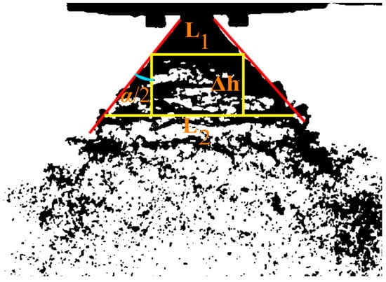
Figure 10.
Diagram of atomization angle.
Through the above process, the atomization angle parameters were obtained for all operating conditions. The atomization angles at different flow rates were analyzed in relation to the pintle stroke and plotted in Figure 11. The graph shows that at the same flow rate, the spray angle increases significantly with increasing pintle stroke.
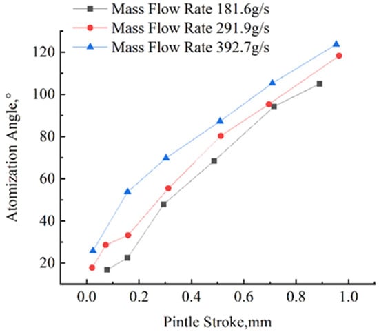
Figure 11.
Relation between atomization angle and pintle stroke.
Combined with the pressure drop, it can be seen that the atomization angle increases mainly because the axial velocity of the liquid decreases at a faster rate, while the radial velocity does not change at a significant rate. The trend and rate of change of the atomization angle are approximately the same for different flow conditions, which also reflects the good consistency of the throttleable pintle-centrifugal injector. As the pintle stroke increases, the rate of change of the atomization angle decreases, which verifies the pattern found in the previous section. This is because at larger pintle strokes, the velocity of the fluid in the injector collection chamber is mainly determined by the tangential holes in the injection panel. The annular slit formed by the two bevels is no longer clearly reflected in the squeezing effect on the liquid at this point.
When analyzed for a fixed pintle stroke, the atomization angle increases as the flow rate increases for the same stroke. This is in line with conventional knowledge. The increased flow rate increases the velocity of the fluid, both axial and radial. Figure 12 shows images of the atomization corresponding to different flow conditions at a pintle stroke of around 0.7 mm.
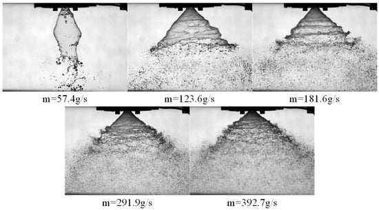
Figure 12.
Flow field diagram for different mass flow rates (Injector 1, t = 1.50 s).
The image clearly reflects the above rule. At the same time, the length of the complete liquid film decreases as the flow rate increases. The distance at which the liquid film breaks up is also gradually advanced, with the consequent larger atomization field size. At the same axial position, the droplet size is smaller. The position of the liquid propellant atomization also influences the adequacy of the contact between the pillar and the oxidizer in the hybrid rocket motor, which further influences the ignition rate and combustion performance of the hybrid rocket motor. By controlling the stroke of the pintle, the throttleable pintle-centrifugal injector is able to adjust the propellant atomization state under various flow conditions, thus adapting to different operating conditions. This helps to achieve a wide range of thrust adjustments for hybrid rocket motors.
4. Conclusions
This study presents and experimentally evaluates a novel throttleable pintle-centrifugal injector system for hybrid rocket engines, focusing on enhancing atomization and achieving precise throttling control. Cold-flow tests with deionized water demonstrated the injector’s ability to regulate injection pressure drop and optimize atomization across a wide flow rate range.
The results highlight the pintle mechanism’s deep throttling capability, which is a key advantage over conventional swirl or impinging injectors, by precisely modulating flow path geometry and pressure drop. Complementing this, the centrifugal injection design induces a swirl effect that significantly enhances atomization by imparting rotational momentum to the oxidizer, independent of pintle stroke adjustments. This synergy not only improves spray cone angle and droplet size distribution, especially at lower flow rates, but also ensures stable and efficient atomization across varying operational conditions.
The main contribution of this work lies in combining the strengths of both mechanisms: the pintle’s throttling capability and the swirl’s atomization enhancement. This dual approach optimizes combustion dynamics, supporting the advantages of hybrid rocket engines such as efficiency, safety and controllability. These findings provide valuable insights into the future development of hybrid propulsion systems.
Future work will involve hot-fire testing of the pintle-centrifugal injector in operational hybrid rocket engines, exploring its long-term performance, combustion efficiency, and integration potential with various oxidizer and fuel combinations.
Author Contributions
Conceptualization, Z.Z.; Methodology, T.L.; Investigation, T.L., Z.Z. and Y.Z.; Data curation, T.L.; Writing—original draft, T.L.; Writing—review & editing, N.Y.; Visualization, T.L.; Project administration, N.Y. All authors have read and agreed to the published version of the manuscript.
Funding
This research received no external funding.
Institutional Review Board Statement
Not applicable.
Informed Consent Statement
Not applicable.
Data Availability Statement
The datasets presented in this article are not readily available because they are undergoing ongoing validation for subsequent research. Requests to access the datasets should be directed to corresponding author on reasonable request.
Conflicts of Interest
The authors declare no conflict of interest.
Nomenclature
| s | the traversal range of the pintle mechanism | mm |
| N | the count of tangential apertures within the injection panelz | |
| Dt | the internal diameter of tangential apertures | mm |
| Dinj | the diameter at the pintle’s nadir | mm |
| Da | the injection panel’s internal diameter | mm |
| θ | the angle of injection channels | ° |
| α | the angle of atomization | ° |
References
- Oztan, C.; Coverstone, V. Utilization of Additive Manufacturing in Hybrid Rocket Technology: A Review. Acta Astronaut. 2021, 180, 130–140. [Google Scholar] [CrossRef]
- Altman, D. Hybrid Rocket Development History. In Proceedings of the 27th Joint Propulsion Conference, Sacramento, CA, USA, 24 June 1991. [Google Scholar]
- Lee, D.; Han, S.; Moon, H. Development of 200 N-Class Throttleable Hybrid Rocket Motor for Lunar Module Application. FirePhysChem 2021, 1, 251–259. [Google Scholar] [CrossRef]
- Okninski, A.; Kopacz, W.; Kaniewski, D.; Sobczak, K. Hybrid Rocket Propulsion Technology for Space Transportation Revisited—Propellant Solutions and Challenges. FirePhysChem 2021, 1, 260–271. [Google Scholar] [CrossRef]
- Tian, H.; Wang, Z.; Guo, Z.; Yu, R.; Cai, G.; Zhang, Y. Effect of Metal and Metalloid Solid-Fuel Additives on Performance and Nozzle Ablation in a Hydroxy-Terminated Polybutadiene Based Hybrid Rocket Motor. Aerosp. Sci. Technol. 2022, 123, 107493. [Google Scholar] [CrossRef]
- Zhao, Z.; Cai, G.; Zhao, B.; Liu, Y.; Yu, N. Experimental Investigation of a Flow-Oriented Throttleable Injector Designed for Throttleable Hybrid Rocket Motor. Acta Astronaut. 2022, 192, 122–132. [Google Scholar] [CrossRef]
- Wang, Y.; Hu, S.; Liu, X.; Liu, L. Boundary Layer Combustion of HTPB/Paraffin Fuels for Hybrid Propulsion Applications. Aerosp. Sci. Technol. 2022, 129, 107850. [Google Scholar] [CrossRef]
- Tian, H.; Jiang, X.; Yu, R.; Zhu, H.; Zhang, Y.; Cai, G. Numerical Analysis of the Hybrid Rocket Motor with Axial Injection Based on Oxidizer Flow Distribution. Acta Astronaut. 2022, 192, 245–257. [Google Scholar] [CrossRef]
- Meng, X.; Tian, H.; Zhu, H.; Wang, Z.; Yu, R.; Guo, Z.; Cai, G. Effects of Aluminum and Aluminum Hydride Additives on the Performance of Hybrid Rocket Motors Based on 95% Hydrogen Peroxide. Aerosp. Sci. Technol. 2022, 130, 107914. [Google Scholar] [CrossRef]
- Thomas, J.C.; Paravan, C.; Stahl, J.M.; Tykol, A.J.; Rodriguez, F.A.; Galfetti, L.; Petersen, E.L. Experimental Evaluation of HTPB/Paraffin Fuel Blends for Hybrid Rocket Applications. Combust. Flame 2021, 229, 111386. [Google Scholar] [CrossRef]
- Mazzetti, A.; Merotto, L.; Pinarello, G. Paraffin-Based Hybrid Rocket Engines Applications: A Review and a Market Perspective. Acta Astronaut. 2016, 126, 286–297. [Google Scholar] [CrossRef]
- Zhao, F.; Zhang, H.; Zhang, H.; Bai, B.; Zhao, L. Review of Atomization and Mixing Characteristics of Pintle Injectors. Acta Astronaut. 2022, 200, 400–419. [Google Scholar] [CrossRef]
- Yao, Z.; Qi, Y.; Bao, W.; Zhang, T. Thrust Control Method and Technology of Variable-Thrust Liquid Engine for Reusable Launch Rocket. Aerospace 2022, 10, 32. [Google Scholar] [CrossRef]
- Meng, X.; Gao, J.; Tian, H.; Niu, X.; Chen, R.; Cai, G. Study on the Dynamic Numerical Simulation of Flow and Combustion in Hybrid Rocket Motors Based on a Discrete Phase Model. Acta Astronaut. 2024, 215, 156–167. [Google Scholar] [CrossRef]
- Shi, P.; Zhu, G.; Cheng, J.; Li, J.; Hou, X. Simulation on Atomization Process of Gas–Liquid Pintle Injector in LRE under Periodic Conditions Based on the VOF to DPM Method. Aerosp. Sci. Technol. 2023, 136, 108222. [Google Scholar] [CrossRef]
- Heo, S.; Jeong, J.; Yoon, Y. Spray Characteristics of a Multi-Slit Type Throttleable Pintle Injector with Different Slit Heights. Acta Astronaut. 2024, 215, 475–492. [Google Scholar] [CrossRef]
- Kim, Y.; Kim, H.; Jeong, J.; Kwon, S. Dual-Plate Injector for Throttling of Hydrogen Peroxide Monopropellant Thruster. J. Propuls. Power 2022, 38, 51–58. [Google Scholar] [CrossRef]
- Zhou, W.; Xu, X.; Yang, Q.; Zhao, R.; Jin, Y. Experimental and Numerical Investigations on the Spray Characteristics of Liquid-Gas Pintle Injector. Aerosp. Sci. Technol. 2022, 121, 107354. [Google Scholar] [CrossRef]
- Li, Z.; Cheng, P.; Li, Q.; Cao, P. Study on the Formation and Maintenance Mechanism of the Stationary Flame at the Head of a LOX/GCH4 Pintle Injector Element. Aerosp. Sci. Technol. 2024, 145, 108899. [Google Scholar] [CrossRef]
- Minato, R. Low Toxic Nitromethane Based Monopropellant for Gas Generator Cycle Air Turbo Ramjet Engine. Propuls. Power Res. 2022, 11, 311–324. [Google Scholar] [CrossRef]
- Nada, T.R.; Hashem, A.A. Geometrical Characterization and Performance Optimization of Monopropellant Thruster Injector. Egypt. J. Remote Sens. Space Sci. 2012, 15, 161–169. [Google Scholar] [CrossRef][Green Version]
- Katsumi, T.; Hori, K. Successful Development of HAN Based Green Propellant. Energetic Mater. Front. 2021, 2, 228–237. [Google Scholar] [CrossRef]
- Cassese, S.; Gallo, G.; Mungiguerra, S.; Cecere, A.; Savino, R. Preliminary Design and Study of 5N HTP Monopropellant Thruster for Small Satellites. Acta Astronaut. 2023, 202, 94–103. [Google Scholar] [CrossRef]
- Meng, X.; Tian, H.; Yu, R.; Lu, Y.; Gu, X.; Tan, G.; Cai, G. Three-Dimensional Numerical Simulation of Hybrid Rocket Motor Based on Dynamic Mesh Technology. Aerosp. Sci. Technol. 2023, 141, 108573. [Google Scholar] [CrossRef]
- Cassese, S.; Mungiguerra, S.; Guida, R.; Cecere, A.; Savino, R. Regression Rate and Performance Analysis via Ballistic Reconstruction of a Small-Scale H2O2-Based Hybrid Rocket Fuelled by Polyvinyl Chloride. Aerosp. Sci. Technol. 2024, 146, 108911. [Google Scholar] [CrossRef]
- Gu, X.; Tian, H.; Wang, J.; Liang, T.; Wei, T.; Niu, X.; Cai, G. Operational Instability of a High-Rotational-Speed Electric Pump in a Hybrid Rocket Motor. Aerosp. Sci. Technol. 2023, 140, 108496. [Google Scholar] [CrossRef]
- Xia, H.; Wang, N.; Yang, J.; Wu, Y. Investigation of Dynamic Mixing Combustion Characteristics in Variable Thrust Hybrid Rocket Motors. Combust. Flame 2023, 250, 112637. [Google Scholar] [CrossRef]
- Yan, D.; Wei, Z.; Xie, K.; Wang, N. Simulation of Thrust Control by Fluidic Injection and Pintle in a Solid Rocket Motor. Aerosp. Sci. Technol. 2020, 99, 105711. [Google Scholar] [CrossRef]


Disclaimer/Publisher’s Note: The statements, opinions and data contained in all publications are solely those of the individual author(s) and contributor(s) and not of MDPI and/or the editor(s). MDPI and/or the editor(s) disclaim responsibility for any injury to people or property resulting from any ideas, methods, instructions or products referred to in the content. |
© 2025 by the authors. Licensee MDPI, Basel, Switzerland. This article is an open access article distributed under the terms and conditions of the Creative Commons Attribution (CC BY) license (https://creativecommons.org/licenses/by/4.0/).