Abstract
Modern manufacturing systems are influenced by the growing complexity of mechatronics, control systems, IIoT, and communication technologies integrated into cyber-physical systems. These systems demand flexibility, modularity, and rapid project execution, making digital tools critical for their design. Virtual commissioning, based on digital twins, enables the testing and validation of control systems and designs in virtual environments, reducing risks and accelerating time-to-market. This research explores the development of digital twin models to bridge the gap between simulation and real-world validation. The models identify design flaws, validate the PLC control code, and ensure interoperability across software platforms. A case study involving a modular Festo manufacturing system modelled in Tecnomatix Process Simulate demonstrates the ability of digital twins to detect inefficiencies, such as collision risks, and to validate automation systems virtually. This study highlights the advantages of virtual commissioning for optimizing manufacturing systems. Communication testing showed compatibility across platforms but revealed limitations with certain data types due to software constraints. This research provides practical insights into creating robust digital twin models, improving the flexibility, efficiency, and quality of manufacturing system design. It also offers recommendations to address current challenges in interoperability and system performance.
1. Introduction
Industry 4.0 has revolutionized the development of mechatronic systems by integrating advanced digital technologies into their design, simulation, and validation processes [1]. Among these technologies, the digital twin plays a central role, enabling detailed modelling and optimization of complex systems. Building on this foundation, virtual commissioning [2] extends the functionality of digital twins by validating system behaviour, including control logic, prior to physical deployment [3,4].
Simulation serves as a foundational tool for time-based analysis of manufacturing processes. It allows engineers to evaluate production times, motion trajectories, and resource utilization, optimizing workflows and identifying bottlenecks. However, traditional simulation methods are limited to static or predefined scenarios and lack real-time adaptability, providing only a high-level view of system performance [5].
In contrast, virtual commissioning leverages event-based simulation, enabling dynamic interaction between the virtual model and the actual control logic of mechatronic systems [6]. This approach integrates automation components, such as PLCs and robot controllers, into the virtual environment. Virtual commissioning facilitates real-time testing of control programs, the verification of safety protocols, and the detection of potential integration issues, reducing the risks associated with physical deployment and ensuring a seamless transition from virtual models to physical systems [7,8,9,10].
The digital twin, as a more advanced and holistic representation, combines the strengths of simulation and virtual commissioning [11,12]. It is a live, data-driven virtual counterpart of the physical system, continuously synchronized with real-time data. This enables digital twins to provide insights into the current state of the system, predict future behaviour through advanced analytics, and facilitate adaptive decision-making [13,14]. Unlike static simulations, digital twins evolve alongside the physical system, making them indispensable tools throughout the entire lifecycle of mechatronic systems [15].
While these technologies offer significant benefits, several challenges remain. DT twins and VC enable enhanced design quality by identifying CAD model deficiencies, such as inefficient motion trajectories or potential collisions [16]. They reduce development time and costs by resolving automation issues in a virtual environment and improve system reliability through real-time validation of the PLC control code [17]. However, the measurable benefits, such as time savings and cost reductions, are often anecdotal or limited to specific projects, lacking systematic quantification. Furthermore, the development of digital twins heavily depends on expert knowledge, resulting in bespoke models that are difficult to standardize and reuse. The interoperability between various simulation and automation tools also poses a significant barrier to broader adoption [18].
Recent review studies emphasize the pivotal role of DT technology in the context of Industry 4.0, particularly in automation, supervision systems, and predictive maintenance. A comprehensive review by Folgado et al. explores the integration of existing and disruptive technologies in automation and supervision, highlighting how Industry 4.0 relies on digitalization and IIoT-enabled solutions for seamless industrial operations [19]. Another review study by Ma et al. focuses on the standardization of predictive maintenance automation through DTs, addressing challenges such as explainability, data efficiency, and scalability and proposing a requirement-based roadmap for DT-driven predictive maintenance [19]. Furthermore, a broader review by Javaid et al. outlines the key applications of DT in Industry 4.0, emphasizing its role in real-time process monitoring, efficiency optimization, and data-driven decision-making [20]. These studies reinforce the significance of DTs as a transformative technology, supporting their practical implementation in industrial automation and manufacturing environments.
This research is motivated by the potential of digital twins and virtual commissioning to bridge the gap between simulation and real-world validation in cyber-physical systems. The primary objective of this study is to explore the development of functional digital twin models that meet the requirements for both simulation and validation purposes. These models must effectively identify design flaws in CAD-based systems, verify the functionality of automation components such as the PLC control code, and support interoperability across diverse software platforms. By addressing these aspects, this research seeks to provide practical insights into the application of digital twins and virtual commissioning, offering solutions to overcome current limitations.
To achieve these goals, this study focuses on a case study involving a specific cyber-physical system. The objectives of this case study are to evaluate the ability of digital twins to identify and address deficiencies in CAD designs, such as inefficient motion trajectories and collision risks. Additionally, this study aims to verify the functionality of automation systems, including the PLC control code, within a virtual environment. Furthermore, it proposes a methodology for creating robust and reusable digital twin models that are universally applicable and compatible with various simulation and automation tools. Finally, this study highlights limitations in existing practices and offers recommendations for improvement.
This article is organized as follows. The Introduction provides an overview of the problem, the benefits and challenges of digital twin technology, and the motivation and objectives of this study. The Related Work Section reviews existing research on digital twins, virtual commissioning, and their applications in cyber-physical systems. The Preliminary Methodology Section details the proposed approach for developing DT models, emphasizing their application for simulation and validation. The case study demonstrates the practical application of the methodology of virtual commissioning to a specific cyber-physical system as Digital Twin and Control System Design Section. The Discussion Section analyzes the findings, addressing the benefits, limitations, and practical insights of the approach. Finally, the Conclusion summarizes the contributions of this study and suggests directions for future research.
2. Related Work
According to the authors of [21,22], virtual commissioning represents a key tool within Industry 4.0, enabling the optimization of the development and implementation of CPSs. Modern digital technologies and high computational power allow for realistic simulation of system behaviour, minimizing the need for physical prototypes and reducing development costs [23]. According to the author of [24], the development of cyber-physical systems is becoming increasingly complex due to the growing sophistication of automation components and robotics [10]. Shortening development cycles and improving product quality require advanced validation and testing methods [25]. The continuous reduction in delivery times and increasing demands for production accuracy have led to the wider adoption of automated quality control, utilizing sensors, cameras, and inspection systems [25].
According to authors [26,27], the development of modern manufacturing systems is nearly impossible without the use of advanced computer simulation methods. The virtual commissioning methodology, based on the HiL principle, enables the validation of control software using a PLC [28]. This approach integrates mechanical, electrical, and software components, increasing the reliability and efficiency of the entire process. Virtual commissioning thus offers significant benefits in reducing development time, improving software quality, and ensuring a more stable integration of new product variants into production [29].
One of the pillars of Industry 4.0 is the digital enterprise concept, which includes a virtual machine applicable in different phases of the cyber-physical system development lifecycle [30]. Each phase involves specific simulation techniques that interconnect, such as transferring building blocks from CAD systems to 3D visualization platforms [31]. During the machine construction phase, FEA and MBS are used, while in the commissioning phase, system behaviour simulation through virtual commissioning plays a crucial role [25]. This innovative process significantly reduces the time required for testing and enhances the quality of manufacturing systems, as shown in Figure 1. According to the authors, compared to the conventional process, where software development is separated from design and assembly, an innovative approach utilizing virtual commissioning allows for parallel validation, leading to significant time savings [32,33].
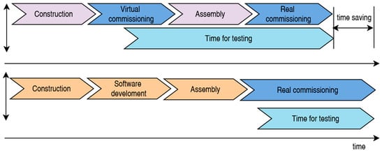
Figure 1.
Comparison of traditional and virtual commissioning processes, illustrating how integrating virtual commissioning reduces testing time and accelerates system deployment.
According to the authors of [34,35,36], virtual commissioning enables the identification and elimination of errors in the design phase, significantly reducing the time required for stabilizing manufacturing systems.
A key element of virtual commissioning is the behaviour model, which enables the simulation of dynamic properties and interactions between system components [37,38]. This model can be represented in multiple ways, depending on the required level of detail. State-based models use state machines and sequential diagrams to define operations and system responses, while physics-based models apply mechanical, electrical, and fluid dynamics principles to simulate movement, forces, and interactions [39]. Hybrid models combine state-based control with physical simulations, providing a more realistic representation of the actual system [40]. The behaviour model created during virtual commissioning can later be integrated into a digital twin, which continuously updates based on real-time operational data, enabling continuous analysis, predictive maintenance, and system optimization [41].
According to the authors of [42,43], virtual commissioning can be considered the initial phase of digital twin modelling, with the main difference between these concepts lying in their interaction with the real system. Virtual commissioning is primarily used in the pre-production phase for testing and validating designs, while a digital twin functions throughout the entire lifecycle of the system and is linked to sensor data from the real environment [11,44]. The integration of virtual commissioning with digital twins allows for different implementation configurations, as illustrated in Figure 2.
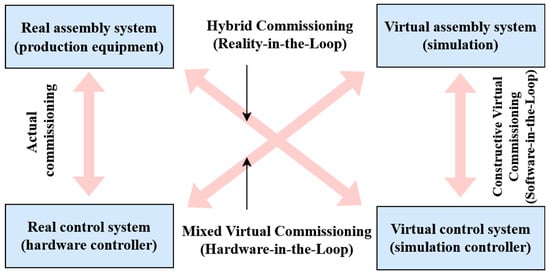
Figure 2.
Classification of commissioning approaches, illustrating actual, mixed virtual, hybrid, and constructive virtual commissioning, based on the combination of real and simulated assembly and control systems.
According to the authors of [45,46], real commissioning combines a physical assembly system with a real control system, ensuring the direct validation of hardware and software integration. Mixed virtual commissioning integrates a virtual assembly system with a real control system, enabling the verification of control software in a digital environment before deployment in actual production. Hybrid commissioning utilizes a real assembly system alongside a virtual control system, facilitating logic testing and optimization without the need for a fully implemented control software. Constructive virtual commissioning represents a fully digitalized approach, where both the assembly system and control system are simulated, allowing for comprehensive analysis and optimization before physical implementation [47].
According to the authors of [48,49], effective virtual commissioning relies on the comprehensive digitalization of engineering processes. A robust software platform must support system design; the creation of virtual models for machines, robotic applications, and material flow; and the development of control programs with virtual testing and validation, including PLC behaviour simulation [50,51]. Available software solutions can be classified into two primary categories. Digital factory [52] software, such as Delmia, Tecnomatix Process Simulate, NX Mechatronics Concept Designer, and CIROS, is designed for comprehensive manufacturing process simulation. In contrast, automation software, including WinMOD, SIMIT, Simster, and FluidSIM, specializes in modelling and testing control systems in HiL and SiL environments.
According to the authors of [10,53], virtual commissioning is a crucial tool for validating cyber-physical systems and is increasingly used as a prerequisite for digital twin implementation. The behaviour model, as part of virtual commissioning, enables realistic simulation and testing of manufacturing systems, significantly reducing errors, shortening commissioning time, and optimizing control programs before physical implementation.
According to the authors of [54,55,56], effective virtual commissioning depends on appropriate software tools that support digital twin simulation, logical behaviour modelling, PLC system emulation, and control program development. As shown in Table 1, these software solutions can be divided into four main categories.

Table 1.
Overview of software solutions for virtual commissioning and digital twin environments, categorized into digital twin simulation, logical behaviour modelling, PLC emulation, and PLC programming, with corresponding references.
The first category includes digital twin simulation tools, such as NX Mechatronics Concept Designer, Tecnomatix Process Simulate, Tecnomatix Plant Simulation, ABB RobotStudio, and CIROS, which enable the precise validation of system design before physical implementation. The second category focuses on logical behaviour modelling of the digital twin, represented by WinMOD and SIMIT, supporting control algorithm testing in HiL and SiL environments.
The third category consists of PLC emulators, including S7-PLC SIM and PLC SIM Advanced, which allow simulation of control unit behaviour without requiring physical hardware. The final category includes PLC programming software, such as Simatic Manager and TIA Portal, which enable early error detection in control software.
According to the authors, integrating these software solutions reduces commissioning time, minimizes testing costs, and enhances the reliability of manufacturing processes, ultimately improving overall system efficiency.
Recent advancements in DT design for VC focus on hybrid modelling, cloud-based solutions, and AI-driven automation. Lian et al. [68] proposed a multi-dimensional fusion modelling method to enhance DT accuracy in smart production lines. Korpai et al. [18] introduced a structured VC framework that simplifies DT integration into manufacturing systems. Lyu et al. [69] developed a cloud-based VC platform for IEC 61499 automation systems, enabling real-time remote testing without local installations. Galkin et al. [70] created an automated DT generation tool for EV charging stations, improving commissioning efficiency. Ismail and Fay [71] applied process mining to DT workflows, optimizing VC time by selectively validating process changes.
While virtual commissioning and digital twin technology are well established in research and industry, a structured methodology for integrating 3D models with behavioural models remains underexplored. Many studies focus on theoretical foundations, software tools, or case studies but provide limited guidance on systematically developing and validating combined 3D and behavioural models in virtual commissioning.
Additionally, while significant progress has been made in real-time data exchange, interoperability, and automation validation, the role of detailed behavioural models within virtual commissioning is not yet fully standardized. Existing research often discusses software capabilities individually, but a comprehensive approach that aligns 3D visualization, LB, and system interactions for accurate DT simulation is still evolving.
This study aims to address these gaps by focusing on the structured development and validation of 3D models and behavioural models within virtual commissioning, ensuring their effective application in real-world industrial environments. By bridging the gap between simulation fidelity and practical implementation, this research contributes to the broader advancement of digital twin methodologies for system validation, efficiency improvement, and automation reliability.
3. Preliminary Methodology
The complete virtual commissioning process is based on a methodical approach that includes three basic phases: analysis, design, and implementation [72]. This systematic approach enables the detailed development and verification of the assembly system in a digital environment before its physical implementation, thus reducing potential errors and optimizing the production process [73].
This section outlines the methodology for integrating a CPS into a DT for real-time data collection, processing, and evaluation. The goal is to establish seamless interoperability between the physical system and its digital counterpart through an effective communication and control framework.
The MPS® 203 I4.0 (Festo Didactic GmbH & Co. KG., Denkendorf, Germany) [74] was selected as the CPS model, serving as a platform to test digital twin integration in manufacturing. A crucial aspect of this research is the choice of a suitable software tool for 3D visualization, system behaviour modelling, and standardized communication protocol support.
The system relies on Siemens PLC as the primary control unit, with a focus on its efficient integration with the digital replica in a simulated environment. The selected solution has to ensure control signal generation, behavioural modelling, and real-time communication, enabling a functional and responsive digital twin.
3.1. MPS® 203 as a Cyber-Physical System for Digital Twin-Based Virtual Commissioning
This system (Figure 3) is a representative model of a small production line that allows for virtual commissioning testing and modelling of a DT. Thanks to its modularity, interoperability, and the integration of Industry 4.0 technologies, it provides suitable conditions for the analysis and verification of control algorithms and for the investigation of the system behaviour under different operating scenarios.

Figure 3.
Physical setup of the MPS® 203 I4.0 automated assembly system as CPS. The system consists of three main stations: Distribution Station (input), Joining Station (material flow), and Sorting Station (output). MES is integrated for production control and monitoring.
The MPS® 203 I4.0 system consists of three automated stations: distribution, assembly, and sorting. At the first station, a cylinder is separated from the gravity bin, and MES system data are written to its RFID chip. The second station uses a pneumatic manipulator to place the lid based on RFID data, while the third station sorts products according to stored specifications.
Designed for one-piece production, the system enables high flexibility and individual customization. Orders are processed in the MES system, which records production and operational data directly onto RFID chips.
Key Industry 4.0 technologies include RFID tracking, MES integration, Big Data for process optimization, and OPC UA/M2M communication for real-time data exchange. The system supports predictive maintenance and integrates AR for training and servicing.
As a cyber-physical system, MPS® 203 I4.0 combines physical and digital components, making it an ideal platform for digital twin research and virtual commissioning, contributing to the advancement of smart manufacturing and industrial automation.
3.2. CAD Representation of the Digital Twin for the CPS Production Line
Digital engineering is applied to develop a digital twin of the assembly system, ensuring an accurate simulation of real system behaviour and seamless integration with control logic.
A CAD model is created in NX 2306 (Siemens AG, München, Germany), incorporating physical properties such as weight, friction, and movable components. Assembly operation simulations are conducted to verify system functionality and identify potential collision zones.
The process involves implementing an LB model, defining control sequences, and establishing sensor–actuator interactions. Various operational scenarios and failure conditions are tested. A control model integrating PLC programming for assembly management is linked to the digital twin, refining and optimizing control logic based on simulation results.
Once imported into the simulation environment, the digital twin is enhanced with control logic, binary and analogue signals, and virtual sensors/actuators, effectively replicating real system behaviour. This process results in a fully functional digital model, ready for simulation, validation, and virtual commissioning.
3.3. The Production Process and Its Planning in CPS
The planning and analysis phase focused on understanding the MPS® 203 assembly system, defining product specifications, and evaluating geometric, functional, and technological requirements. Key aspects included assembly steps, sequencing, and clocking time, ensuring optimal production efficiency and flexibility.
This study identified necessary tools, automation elements, and potential bottlenecks, addressing station synchronization, production control, and logistics optimization. Based on these findings, a detailed assembly process plan was developed, serving as the foundation for digital twin modelling and virtual commissioning.
3.4. Software and Hardware Framework for Digital Twin Implementation
Choosing the right software and hardware is key to creating and testing a digital twin. Tecnomatix Process Simulate 17.0 (Siemens AG, Germany), which allows advanced modelling and virtual commissioning, was used for this research. Simatic Manager, interfaced to the emulated PLC via PLCSIM, was used to create and test the control codes, thus applying the SiL method. This combination provided a realistic simulation of the CPS management room, allowing thorough testing prior to physical implementation.
3.5. Integration and Validation Through Virtual Commissioning
The next step in digital twin modelling was virtual commissioning, which enabled the simulation and verification of the complete assembly system before its physical implementation. This phase involved integrating the digital model with control systems, testing interoperability between software platforms and hardware, and validating control algorithms in real time.
Additionally, the system’s functionality was assessed under various operating scenarios, such as product variations or fault conditions, to identify potential issues that could impact productivity. This step ensured an early evaluation of the system’s behaviour, allowing for necessary optimizations before moving to physical implementation.
3.6. Verification and Validation of the Digital Twin Through Simulation
Simulation and functional testing represent a crucial phase in validating the digital twin. This stage involves simulating various operating scenarios to identify design flaws, such as collision zones or improperly implemented control logic. The digital twin is linked to the PLC control logic, allowing the verification of code implementation under simulated conditions.
Additionally, the model’s interoperability is assessed by testing its functionality across different software environments and ensuring compatibility with other simulation tools. This phase is essential for detecting and resolving potential issues before the system’s physical implementation, ensuring a more reliable and optimized deployment.
4. Digital Twin and Control System Design
The first phase of this process consists of two key steps: modelling the physical 3D model and modelling the LB, which together form a comprehensive virtual model (Figure 4). The design of the digital twin and control system follows the systematic methodology outlined in Figure 5, which includes digital twin design, control system integration, and virtual commissioning testing. These steps ensure accurate system representation, enabling seamless integration with control logic and real-time validation.
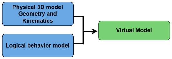
Figure 4.
The first phase of digital twin design: integration of the physical 3D model (geometry and kinematics) with the logical behaviour model to generate a virtual model.
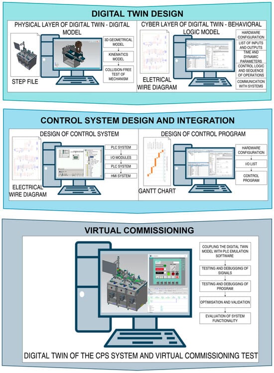
Figure 5.
Diagram illustrates the systematic methodology for digital twin development, control system integration, and virtual commissioning in industrial automation.
4.1. Geometry and Kinematics Model
A 3D geometric model not only meets technical requirements but also enhances visualization, improving user acceptance of virtual commissioning. When a PLM system is integrated within a digital enterprise, and digital models are utilized comprehensively (e.g., Siemens Teamcenter PLM 13), no conversion between CAD models across different software platforms is necessary.
In the absence of a unified PLM platform, various software tools must be used for CAD data conversion. To facilitate seamless data exchange between different software environments, open standards such as STEP and VRML are commonly employed. Consequently, most software vendors provide dedicated import/export interfaces, ensuring interoperability across platforms (Table 2).
Table 2.
Comparison of software tools for virtual commissioning and their supported CAD import formats.
This applies to so-called “raw” models (i.e., unprocessed data) that lack kinematics or sensor integration, both of which are essential for virtual commissioning. Kinematic conversion is currently either not supported or only partially enabled through the AutomationML format.
AutomationML is an open standard designed primarily for data exchange in the engineering process of manufacturing systems across different software platforms. It facilitates interoperability by standardizing model representation, enabling seamless integration within heterogeneous digital environments [75,76].
In this case, the STEP format was the only available model format, requiring conversion before integration into the simulation environment. To achieve this, the CAD software NX 2406 (Siemens AG, München, Germany) was used to transform the model into the JT format, which is the required import format for Tecnomatix Process Simulate. This conversion ensured compatibility and enabled seamless integration of the 3D model into the virtual commissioning workflow. Since Process Simulate operates with a model database and supports model imports exclusively in the JT format, the models must be stored in a monolithic structure within a directory formatted as COJT, as shown in Figure 6. This requirement ensures proper integration and compatibility within the simulation environment, allowing seamless manipulation and interaction of the digital twin components.
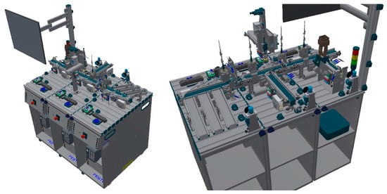
Figure 6.
Three-dimensional digital twin model of the MPS® 203 I4.0 assembly system, prepared for integration into the simulation environment.
As the test model for virtual commissioning, the “Distribution” station of the MPS® 203 I4.0 system by Festo Didactic was selected. This station serves as the digital twin, enabling direct comparison with the physical MPS® 203 I4.0 system. The station is an integral part of the assembly system, designed in accordance with the Industry 4.0 reference architecture, ensuring compliance with modern cyber-physical production principles.
The “Distribution” station is responsible for feeding cylinders of various materials and colours onto the conveyor belt. This task is performed by an automated feeding device controlled by a pneumatic cylinder DSNU-8-100-PPV-A (19182), Festo AG & Co. KG, Esslingen, Germany (Figure 7). The pneumatic actuator ensures precise and repeatable handling of the components, supporting the automated material flow within the assembly system.
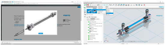
Figure 7.
Pneumatic cylinder DSNU-8-100-PPV-A (19182), Festo AG & Co. KG, Esslingen, Germany and the generated pneumatic cylinder model and subsequent export in the Festo Design Tool 3D environment.
As previously mentioned, Process Simulate operates with models stored in a database following a predefined format. This database can be local, created as an eM Server “System Root”, or hosted externally on a server. To facilitate structured team collaboration, project data in Tecnomatix Process Simulate are centrally managed in an Oracle database on the server. Within this eM Server, each project has a dedicated “System Root”, serving as an interface between client computers and the database, ensuring efficient data management and synchronization across the development environment.
The import of individual equipment models is only possible after defining the component type within the simulation (“Define Component Type”). Assigning this classification to a model in the database enables or restricts specific functionalities based on the component type (e.g., robot, clamp, workpiece, device, sensor, human, tool, gripper, etc.). These functionalities become accessible only after the project is created.
A Tecnomatix Process Simulate project primarily consists of a database of virtual models and simulation studies. Within the database, a distinction is made between production resources (Resources) and workpieces (Parts), ensuring a structured organization of manufacturing components for simulation and validation.
If all conditions for inserting a model into the project are met (JT file format, database creation, and component definition), the model is classified within the project database upon insertion. Its categorization depends on whether it represents a workpiece (Part) or a production resource (Resource), ensuring proper organization and functionality within the simulation environment.
The kinematic model of the resource is created in the Kinematics Editor by defining joints, motion axes, degrees of freedom, and movement limits. A reference base is assigned, linking model parts to their respective axes (“Link”). Joints (“Joints”) can be prismatic or revolute, with defined limits, speed, and acceleration (Figure 8). More complex structures can be generated using “Create Crank”.
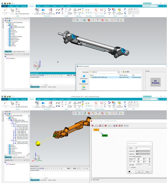
Figure 8.
Insertion of the pneumatic cylinder as a production resource into the project database and creation of its kinematic model with defined joint properties.
Modelling kinematics for complex geometries is a manual process that requires expertise and time. Once completed and confirmed via “End Modelling”, the kinematic data are stored in the database for reuse in other projects.
In this study, the pneumatic cylinder of the MPS “Distribution” station was modelled, converted to JT format, and imported into the project database, where kinematics was assigned. Actuating the pneumatic cylinder extends the feeding mechanism, releasing the cylinder into the working position, as shown in Figure 9.
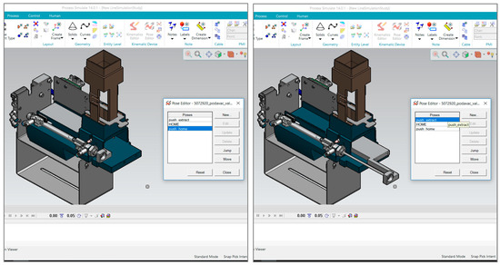
Figure 9.
Kinematic modelling of the pneumatic cylinder in the MPS “Distribution” station. The model was converted to JT format and imported into the project database, where kinematics was assigned. Actuating the pneumatic cylinder extends the feeding mechanism, releasing the cylinder into the working position.
Finally, motion positions are defined in the “Pose Editor”, either as predefined limits or manually. Here, two positions are set: “push_home” and “push_extract”, essential for automation, as they are controlled by signals and verified by sensors. The HOME position is pre-configured.
For digital twin models, mechanisms are restricted to generating either translational or rotational motion, as all complex movements can be decomposed into these fundamental types. Translational motion involves movement along a straight path, typically achieved through linear actuators, pneumatic cylinders, or guide rails. Rotational motion occurs around a fixed axis and is implemented using rotary joints, servo motors, or gears.
In digital twin simulations, these motions are modelled and parameterized to reflect real-world system behaviour, ensuring accurate representation of kinematic properties. The combination of linear and rotational elements allows for the simulation of more complex robotic and automation systems while maintaining a structured and computationally efficient model.
Linear motion is characterized by translational displacement along a single axis. The kinematic state of a system is defined by position, velocity, and acceleration as functions of time. The standard kinematic equations for constant acceleration are as follows:
where s is the displacement, v is velocity, v0 is initial velocity, a is acceleration, and t is time.
In a homogeneous transformation matrix form, pure translation along an axis x, y, or z can be represented as
where x, y, and z represent linear displacements along the respective axes.
Rotational motion involves movement about a fixed axis and is described by angular displacement (θ), angular velocity (ω), and angular acceleration (α). The kinematic equations for rotational motion are analogous to those for linear motion:
where θ is angular displacement, ω is angular velocity, ω0 is initial angular velocity, and α is angular acceleration.
In matrix representation, a pure rotation about an axis is given by the following rotation matrix for a rotation about the z-axis:
Similar matrices exist for rotations about the x- and y-axes.
4.2. Logic Behaviour Model
The behaviour model simulates the logical and temporal behaviour of real system components in relation to their connected control units. It consists of simulation components that replicate real-world devices, such as valves and actuators, ensuring accurate system representation.
Depending on the standardization level within a given company, these components may be available as library elements in the selected virtual commissioning software. The number and type of resources required for the behaviour model are typically documented in planning materials, such as electrical or pneumatic schematics.
Software tools with automated modelling capabilities can streamline the process of creating logical behaviour models. To develop a PLC-based control model, an interaction simulation model must be established in the form of operations. These operations define interactions between production resources (Resources) and workpieces (Parts), such as material flow during assembly.
In Process Simulate, the ability to define specific operations depends on the assigned component type. In this study, the system allows for “Object Flow Operation”, where the device can be moved within the simulation, and “Device Operation”, where motion follows predefined kinematics. Two operations were created: the extension and retraction of the feeding mechanism, as shown in Figure 10.

Figure 10.
Definition of device operations in Process Simulate. “Object Flow Operation” enables movement within the simulation, while “Device Operation” follows predefined kinematics. Two operations were created: extension and retraction of the feeding mechanism.
These operations are added to the operation tree and interconnected to ensure sequential execution. In this case, the operations can be simulated since the simulation is executed in Time-Based Simulation Mode, allowing for realistic timing and process validation.
Logical blocks are specialized resources with input and output connections for signal integration. They can be controlled using logical commands, Boolean operations, and mathematical functions (Figure 11), enabling dynamic interaction within the simulation environment.
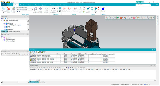
Figure 11.
Generation and visualization of input and output signals for the feeding mechanism in the Signal Viewer window.
Position sensors can be manually created for each actuator using the “Sensor Command” function, with two available types: “Joint Value Sensor” and “Joint Distance Sensor”. The “Joint Value Sensor” provides binary position detection, while the “Joint Distance Sensor” continuously measures the actuator’s position throughout its movement. Each sensor can be assigned multiple attributes, including detection type and tolerance, as shown in Figure 12.
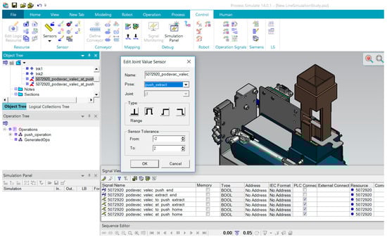
Figure 12.
Definition of attributes for the proposed position sensor for the feeding mechanism.
A key aspect of the simulation is the definition and placement of sensors for object detection and position tracking. A general proximity sensor can be selected, which does not correspond to a specific physical sensing principle (inductive, capacitive, optical, ultrasonic, or magnetic) but can interact with assigned objects. Additionally, specialized sensors such as barcode scanners, cameras, or temperature sensors can be defined with specific properties.
In this study, a presence sensor was required to detect cylinders in the gravity feeder, which was also modelled. An optoelectronic sensor, functioning as a light barrier, was implemented, with the transmitter and receiver diodes routed into the feeder via optical fibres (Figure 13). The sensor parameters, including beam diameter, width, and length, were adjustable to ensure proper object detection during the simulation.

Figure 13.
Insertion of the sensor model as a light sensor for detecting yellow-coloured objects within the feeding mechanism. The sensor is integrated into a virtual model to enable object detection and interaction within the simulation environment.
Once all motion control and automation signals were defined and assigned, they were verified in the “Signal Viewer” window. This tool allows for adding and adjusting signals that control devices, material flow, and simulation execution. A total of seven signals were generated, with five signals assigned to the PLC (three input and two output signals) and linked to their respective sources.
Once all control and automation signals for the assembly system are designed and correctly assigned, they can be verified in the “Signal Viewer”. This tool allows for monitoring signal flow and adding additional signals, if necessary, to control devices, material flow, or overall system execution within the simulation.
In this study, a total of seven signals were generated, of which five were assigned to the PLC—three input signals and two output signals, each linked to a designated source. This configuration ensures proper synchronization between the digital twin and the control system, allowing for accurate simulation of the automation process, as shown in Figure 14.
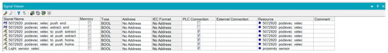
Figure 14.
Table of generated signals for controlling the feeding mechanism. The signals are paired based on their signal names rather than addresses, ensuring proper communication and synchronization within the simulation environment.
These individual signals must be connected to the control system to enable simulation via the PLC. Through signal mapping, the movement of the device models is executed, ensuring accurate representation of the automation process within the virtual commissioning environment.
4.3. Connection via Standardized Interfaces and Simulation Control
The digital model of the assembly system can be connected to a PLC or a robotic control system to enable virtual commissioning. To test PLC programs on a simulated device, it is essential to establish a connection between the simulation system and the PLC control system.
Currently, there are three different connection methods for integrating a virtual commissioning simulation system. A direct connection to the physical PLC hardware is established via an OPC DA server (Figure 15). While OPC is widely supported, it does not simulate hardware configurations, meaning the timing behaviour of the bus system is not considered. In systems with a high number of networked devices, bus communication delays may occur, affecting system behaviour and requiring mapping within the simulation.
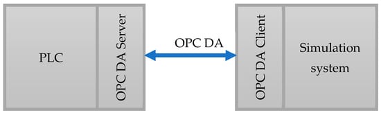
Figure 15.
Schematic representation of the connection between the PLC and the simulation system via OPC communication, utilizing an OPC DA Server and OPC DA Client for data exchange.
Another critical limitation is the lack of support for secure communication, such as safety signals (e.g., emergency stop or safety door contacts). Many systems transmit both standard and safety signals over the bus network, using protocols such as PROFISAFE (PROFIBUS/PROFINET) or INTERBUS-Safety. However, due to the absence of a bus system in OPC communication, safety signals cannot be simulated, as OPC DA does not provide direct access to these signals.
To execute virtual commissioning with an OPC DA connection, PLC program modifications are necessary to enable operation without the safety logic. Due to these limitations, direct OPC DA connections are suitable only for simple simulation models where safety communication is not required and bus system timing can be neglected.
Another approach for connecting the simulation tool to a PLC is direct bus communication. In this setup, the simulation computer is equipped with a bus interface card, allowing it to function as a slave device on the real bus network. Data exchange between the bus card and the simulation tool is handled via a driver interface. This connection method is currently supported by software such as WinMOD, whereas DELMIA Automation and Process Simulate Commissioning currently lack direct bus interface support.
A third connection method is bus emulation, where a dedicated hardware setup is connected via the same bus system used by the PLC and emulates bus components. Bus emulation is available for commonly used industrial networks, including Siemens SIMBA PROFIBUS, Siemens SIMBA PNIO (PROFINET), Mewes & Partner Interbus Emulator, and Siemens PLCSIM Emulator.
To integrate a Process Simulate model with a PLC control system, the simulation mode must be switched from Time-Based Simulation to Line Simulation (event-based simulation).
The connection settings are configured in the Options-PLC tab. The system supports virtual commissioning through several methods: Internal Cycle-Event Simulation (CEE) and PLC emulator connection via SIMIT, PLCSI, or external connection, where the data update rate can be configured (default: 200 ms).
Multiple connection protocols are available, including OPC DA, OPC UA, direct simulation device interfaces, and the PLCSIM Advanced emulator from Siemens.
For system setup, communication verification, and signal testing, the initial step is selecting an emulator, such as PLCSIM, which enables signal transfer from the virtual control system to the simulation model when using a Siemens PLC. For non-Siemens PLCs, communication has to be configured via OPC DA from the start. In this study, the DELTALOGIC OPC server was used for PLC integration.
Once communication between the PLC and the simulation model is established, signal-level mapping must be configured. Since the simulation model includes a behaviour model and predefined signals, it is sufficient to assign addresses to input and output signals and establish the appropriate connections—either locally, via PLCSIM, or through an OPC server.
As shown in Figure 16, the generated signals are assigned addresses in IEC format, defined as BOOL-type signals, and linked to the PLC, either directly through the emulator or via external communication interfaces.
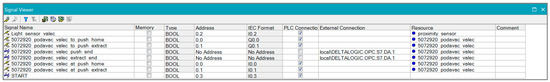
Figure 16.
Table of signals with assigned addresses and connections to the PLC, including external OPC DA communication links for data exchange between the simulation model and the control system.
Regarding the addresses of input and output signals, they must be uniquely assigned according to the actual electropneumatic wiring diagram of the feeding device, ensuring consistency between the virtual model and the physical system, as shown in Figure 17.
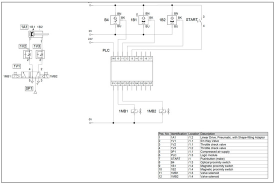
Figure 17.
Electropneumatic schematic of the pneumatic feeding mechanism, illustrating the connection between the PLC, sensors, actuators, and control components.
The display, labelling, and identification of inputs and outputs follow the standards ISO 1219-2 (2012-09) [77] and IEC 81346-2 (2009-10) [78]. Each electrical input connection is assigned a corresponding PLC address (Table 3) and variable names based on the simulation model created in Process Simulate, ensuring consistency between the virtual and real systems.
Table 3.
Mapping of identification components to PLC addresses and corresponding PLC variables for the pneumatic feeding mechanism.
For signal monitoring and control, the appropriate signals are assigned to the simulation panel before starting the simulation. This panel allows for real-time signal tracking, control, and the definition of initial conditions (Figure 18), ensuring proper system behaviour during the simulation process.
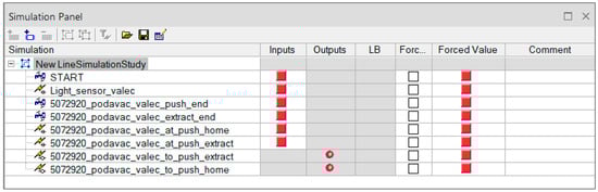
Figure 18.
Simulation panel for monitoring and controlling individual signals. In the Simulation Panel, green (1) indicates an active signal, while red (0) represents an inactive signal, showing the current state of inputs or outputs in the simulation. The square represents the inputs and the circle the outputs.
4.4. Material Flow of the Simulation Model of Digital Twin
A virtual commissioning study should include the movement of components, assembled subunits, and final products to enhance simulation realism. While this aspect is less critical for PLC system testing, it is essential for the accurate visualization of the assembly process.
According to this process implemented in the MPS (Figure 19), the material flow was analyzed, and the PLC operational program was developed to manage the sequential manufacturing operations. The process includes key steps, from the entry of the semi-finished product into the system to data writing and retrieval, component assembly, quality control, and final product expedition. Based on this sequence, the PLC program defines logical operations, control sequences, and decision mechanisms, ensuring precise coordination of manufacturing steps and optimizing the overall production process.
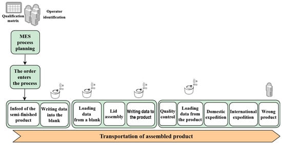
Figure 19.
MPS process flow, illustrating MES process planning, material flow, data handling, assembly, quality control, and final product expedition. The process serves as the basis for the PLC operational program, ensuring automation and synchronization of production tasks.
To integrate these elements, parts and assembled products must be created as “Parts” and imported similarly to other devices in JT format within a COJT folder. These components must be assigned to the “Part Prototype” category to function as assembly elements rather than system devices. Importing, editing, and defining movement operations for individual parts is only possible in Time-Based Simulation Mode, ensuring proper synchronization within the simulation environment.
In the project, three types of cylinders—silver, black, and red—were imported. All three types follow the same “Object Flow Operation”, where they are placed into the gravity feeder and fall onto the feeding mechanism base.
As a result, three virtual output signals were created to initiate the insertion movement of the cylinders, along with three virtual input signals to confirm the completion of these operations, as shown in Figure 20.
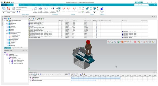
Figure 20.
Definition of new parts, their movement operations, and generation of virtual signals for motion.
In event-based simulation, parts do not appear in the standard way but must be generated using the “Generate Appearances” command. This process creates the visual representation of parts, which are referenced and assigned to specific operations.
These parts must be organized within the material flow, where the Material Flow Browser displays operations, parts, and material transitions between operations, as shown in Figure 21. This tool enables visualization and control of how parts move through the simulation in event-driven mode.
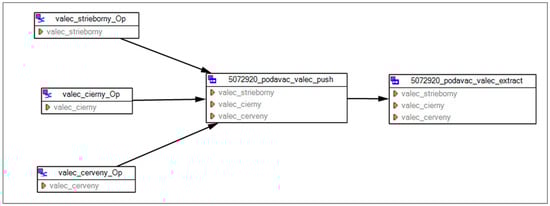
Figure 21.
Generated material flow of individual assembled parts. The diagram illustrates the flow of silver, black, and red cylinders through the feeding and extraction operations.
Creating material flow is crucial for simulating the movement of assembled products. To ensure that a product interacts with devices during its motion, it must be assigned to moving objects. This is achieved through the “Attach Event” command, which links the product to a moving object, and the “Detach Event” command, which releases it, allowing for realistic motion simulation within the system.
4.5. Control System Design
To effectively control and operate the simulation model, a control program must be created. In this case, Siemens SIMATIC Manager was selected due to its simplicity and comprehensive functionality. The first step involved creating a new project and defining a new station (SIMATIC 300). The selected hardware PLC was CPU 313C-2DP.
After initializing the program and defining variables in the Symbol Editor, the logic was structured according to the sequential operation of the feeding system in automatic mode.
The advantages of virtual commissioning became evident during programming. Once the virtual model was linked to the control system, the program could be tested and debugged in real time. If errors were present in the logic, the system’s behaviour immediately reflected these issues, allowing for efficient troubleshooting and optimization before deployment.
5. Testing and Verification of the Virtual Commissioning Model
The developed virtual model as the digital twin of the assembly system was prepared for testing and verification within the virtual commissioning framework. Following the creation of 3D models with defined logical behaviour, the layout of the automated assembly system was established.
The layout configuration is a crucial step that takes place prior to virtual commissioning, ensuring proper alignment of the simulation model with the PLC control system before establishing their connection. This phase ensures that the spatial arrangement of components is optimized for seamless integration between the virtual environment and the real-world automation system.
The methodological approach to virtual commissioning was thoroughly developed for a single device within the entire assembly system to ensure clarity and a simplified process demonstration. The layout configuration is based on a 3D design of the entire system, created in a CAD environment.
Virtual commissioning is carried out by connecting the simulation model, incorporating all the attributes mentioned in previous sections, with the PLC control system (either virtual or physical) through standardized interfaces such as OPC DA, emulators, or bus systems. Once the connection is established, it can be tested via the “Sequence Editor”. This editor allows for the testing of individual operations, either in time-based or event-based simulation modes. Additionally, it enables the generation of movement and paths for industrial robots, tools, and products through the “Path Editor”. The “Sequence Editor” essentially functions as a Gantt chart for the operations created in earlier steps. Control is facilitated through buttons like Play, Pause, Reverse, and Forward, with the ability to adjust simulation accuracy and speed based on time requirements.
By clicking the Play button in the sequence editor, the simulation is initiated. However, the step size between two simulation times must first be specified. This requirement significantly impacts the accuracy of the simulation. Once the simulation is started and a PLC connection method is selected, the system automatically proceeds. In this case, Siemens PLCSIM is used for the PLC connection.
The tested control program communicates with the virtual model via PLCSIM. A valuable tool for testing the control program is the “Simulation Panel”. When the simulation model is in “online” mode, the virtual commissioning of the assembly system can be applied and tested.
In this way, a simulation model of the entire assembly system can be created. Individual virtual models, whether with defined kinematics and behaviour models that will move or virtual static models (such as tables, barriers, etc.), must be imported into the project separately.
In Process Simulate, imported objects can be repositioned using the “Manipulator” function, allowing precise arrangement of system components. The assembly system model was fully developed in Tecnomatix Process Simulate, where the entire process was simulated and verified using time-based simulation. The model is now prepared for event-based simulation testing, ensuring its readiness for further validation and optimization, as shown in Figure 22.
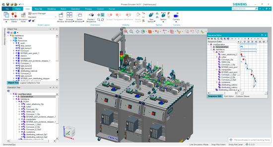
Figure 22.
Created virtual model of the automated assembly system in Process Simulate. The system is shown with its components, including the control sequence editor for operation management and sequence visualization.
As shown in Figure 23, the virtual commissioning of the assembly system can be characterized as a simulation model that integrates both the virtual system model and the control system. The virtual system model includes digital representations of objects, system layout, and material flow, while the control system consists of a PLC, a control program, and an HMI panel. This integration enables a comprehensive validation and testing environment for the automated system before physical deployment.
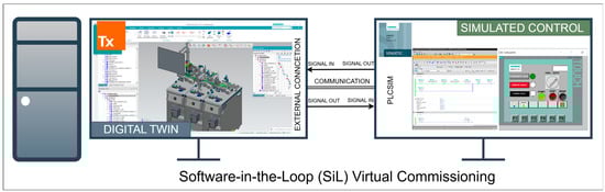
Figure 23.
The virtual commissioning project of the assembly system was implemented using an SiL approach, where the digital twin model and the simulated control system operated simultaneously on separate monitors. One monitor displayed the simulation model representing the digital twin, while the second monitor ran the control program, allowing real-time testing and verification. This setup enabled direct interaction between the control logic and the simulated system, ensuring accurate evaluation of system behaviour and response within the virtual commissioning environment.
Modern assembly systems are typically controlled by PLCs, which are currently the most widely used and suitable solution for industrial automation. PLC sequential control operates using a symbolic table of input and output signals and follows a scanning cycle, effectively emulating the behaviour of parallel circuits that respond in real time.
When the program is executed in the PLC, it continuously performs the scanning cycle, ensuring real-time processing of input signals, logic execution, and output updates, which are crucial for the efficient and reliable operation of automated systems.
PLC control communicates with the virtual model exclusively through a communication protocol using input and output symbols. While input symbols receive electrical signals from devices, output symbols are used to send commands to actuators and other system components, ensuring proper interaction between the PLC and the simulated system.
The digital twin model of the assembly system was tested and verified using a virtual commissioning tool, where signals were mapped through the integration of Tecnomatix Process Simulate 14.0.1 and Siemens TIA Portal V14. This setup was also chosen to enable model control via an HMI panel, developed in SIMATIC WinCC V14.
Signals generated from the logical behaviour models were exported from Tecnomatix Process Simulate 14.0.1 and imported as symbols into the PLC tag table. Figure 24 presents an overview of the symbol table, where variable names, data types, IEC format addresses, PLC connection methods, and comments are defined. In Figure 25, the PLC control program in LAD is displayed in online mode, monitoring the real-time status of the system.
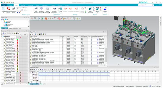
Figure 24.
Overview of the symbol table in Process Simulate, displaying variable names, data types, IEC format addresses, PLC connection methods, and comments, facilitating efficient signal mapping and integration between the virtual model and external control systems; the red colour indicates both true and false states, depending on the context, as seen online.
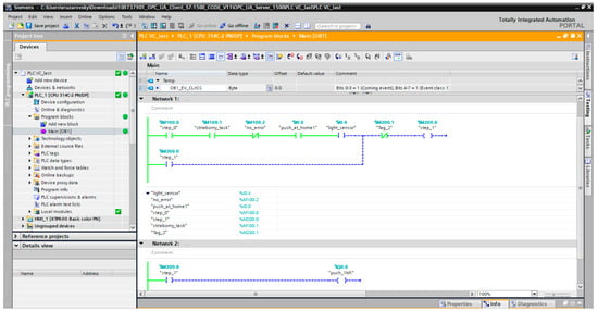
Figure 25.
Testing and verification of the PLC control program on the digital twin model of the assembly system.
The virtual model of the assembly system was designed to support multiple communication protocols, enabling PLC control program testing and verification of created programs and sequences during testing. The PLC control program was developed in Siemens TIA Portal V14, while the virtual assembly system was controlled through commands displayed on the HMI panel, ensuring real-time interaction and functional validation of the automation process.
6. Discussion
Practical experience with virtual commissioning applications has demonstrated that modern simulation methods and digital enterprise tools can be effectively utilized in the design and validation of automated assembly systems, particularly in the testing phase. This approach enables early verification of the virtual model’s accuracy, focusing on layout optimization, collision detection, and PLC control program testing, even before the physical system is manufactured.
However, it has also become evident that virtual commissioning must be strategically integrated into the entire planning and engineering workflow rather than being treated as an isolated process step. To maximize its benefits, it is essential to analyze the existing development process, clearly define objectives, and select the most suitable digital enterprise tool based on the specific requirements of the application domain.
Further advancements in digital enterprise environments and automation technology are expected to facilitate the adoption of virtual commissioning. Key developments include the expansion of open data exchange formats, such as AutomationML, and the integration of standardized interfaces in simulation and automation software.
While Matlab Simulink is widely used for control system simulation, digital twin models are integrated into real automation workflows for virtual commissioning and system validation in industrial applications. Unlike Matlab-based simulations, which are operated offline, the digital twin methodology is synchronized in real time with PLCs, SCADA, and MES systems, ensuring direct interaction with industrial processes. Instead of relying on external computational engines like Matlab, an internal scripting solution is implemented for LB modelling, allowing seamless integration within the simulation framework while maintaining real-time execution compatibility.
Additionally, progress in software-based control systems for robots and PLCs will enhance the capabilities of virtual commissioning. Improvements such as direct access to hardware control functions, increased instance capacity (e.g., multiple controllers operating on a standard PC), and simulation of safety functions could significantly enhance the efficiency and profitability of virtual commissioning applications.
Despite its advantages, virtual commissioning has several limitations that must be addressed. One major challenge is the time-intensive manual modelling of kinematics, which highlights the need for automated methods to generate kinematic models more efficiently. Additionally, during the design of logical behaviour models, it is crucial to consider various operational scenarios to enhance simulation accuracy.
Another limitation is the inaccuracy of timing estimates within the logical behaviour model. Since movement durations are typically based on approximations, achieving a 1:1 match between the simulation model and the real system remains difficult. This means that some objectives of virtual commissioning cannot be fully realized, and the simulation reaches its limits in real-time capabilities, though this is not the primary focus of Tecnomatix Process Simulate.
Furthermore, Tecnomatix Process Simulate is a complex software tool requiring significant investment not only in licencing costs but also in training and long-term employee education. As it operates on database-driven architecture, users must have basic knowledge of database installation and management.
Finally, the complexity of interfacing between the simulation environment, OPC DA server, and PLC should not be underestimated, as demonstrated in this project. The proper configuration and integration of these components are essential to ensure seamless communication and accurate simulation results.
In this context, it is important to acknowledge that the PLC model S7-300 (CPU 313C-2DP) and WinCC/TIA Portal V14 used in this study represent older hardware and software versions, which are considered legacy systems in modern automation. However, these technologies are still widely used in industrial practice, and one of this study’s objectives was to evaluate their behaviour, interoperability, and limitations within the virtual commissioning process. Understanding the constraints of legacy systems is essential for assessing migration strategies and ensuring compatibility with contemporary automation solutions.
Based on these findings, future work will focus on integrating the S7-1500 series PLCs, OPC UA, and SIMIT to develop and validate behavioural models in a more advanced and scalable automation environment. These upgrades will allow for a more precise representation of system behaviour and improve the interoperability of virtual commissioning tools with modern industrial applications.
Despite its limitations, the future of industrial automation lies in digital enterprise and virtual commissioning. The benefits outweigh the challenges, as the objectives outlined above are achievable with continuous advancements in simulation and automation technologies. In this study, the assembly system was successfully replicated and functionally validated in Tecnomatix Process Simulate, demonstrating the potential of virtual commissioning.
One key strategy for reducing time and costs is the adoption of “Smart Components” provided by suppliers, like the widespread availability of CAD models today. Standardizing behaviour models, kinematic models, and parameter customization would significantly improve simulation efficiency, aligning with Industry 4.0 standards.
The results of this study should be interpreted in relation to previous research and established working hypotheses. The findings demonstrate that virtual commissioning effectively enhances the design, validation, and optimization of assembly systems, contributing to the broader field of digital manufacturing.
However, further research is needed to refine kinematic modeming, real-time simulation accuracy, and seamless PLC integration. Future studies should focus on developing automated methods for kinematic model generation, improving real-time synchronization between simulation models and physical systems, and exploring the interoperability of different virtual commissioning tools. These advancements will drive the continuous evolution of smart manufacturing and further enhance the implementation of Industry 4.0 technologies.
During the virtual commissioning process, we encountered several challenges that highlighted key areas for further research and optimization. One of the most significant findings was the impact of the integrator’s experience level on digital twin preparation time. While experienced users were able to streamline the setup efficiently, less experienced users required significantly more time to achieve the same level of accuracy. This variability suggests that developing standardized workflows and automation tools could further enhance the efficiency of virtual commissioning.
Additionally, we observed that not all signals used in real industrial projects are visually represented in the 3D model. Certain system components, such as communication signals, printer interactions, and safety protocols, do not have direct graphical counterparts but are still crucial for system functionality. Our study confirmed that virtual commissioning can effectively test both graphical and non-graphical signals, which broadens its applicability beyond visual simulation.
To address these challenges, future research will explore advanced software tools such as WinMOD and SIMIT, which specialize in signal validation and system behaviour simulation beyond purely graphical models. Furthermore, a comparative study between Delmia and Process Simulate will be conducted to evaluate their suitability for different industrial applications. While Process Simulate was chosen for this study due to its widespread use in the automotive industry, further investigations will provide deeper insights into the advantages and limitations of different virtual commissioning platforms, particularly in the context of robotic system integration.
7. Conclusions
In the pre-production phase, digital technologies are utilized to integrate the physical system with its virtual counterpart. The digitalization of the entire pre-production process accelerates system development and enables error detection and correction before the physical construction of equipment, machines, and systems.
Verified digitalization methods, such as virtual commissioning, are widely regarded as a promising approach to addressing challenges associated with physical commissioning. However, developing an accurate virtual simulation model requires significant effort and a high level of expertise. Successful implementation demands comprehensive knowledge in machine and system design, mechanics, mechatronics, automation, programming, and control algorithm development. These interdisciplinary competencies are crucial for ensuring the efficiency and accuracy of the virtual commissioning process.
Virtual commissioning of assembly systems has been a research topic in both academic and industrial fields for over a decade. The primary objective in this area is the development of a systematic methodology for simulation studies, along with a general framework for the planning, implementation, and execution of virtual commissioning.
This study presents the concepts and methodologies for implementation, clarifies the requirements, and defines the software platforms and environments necessary for virtual commissioning. The applicability of these approaches in digital system design was verified by performing virtual commissioning of the MPS® 203 I4.0 automated assembly system from Festo Didactic, Germany. The research focuses on building a simulation model, which is a key component of virtual commissioning.
The motivation for this research arises from challenges encountered during the real commissioning of assembly systems, where design flaws required costly modifications and PLC control programs could not be tested without a physical system, posing risks of damage. Investigations into potential solutions revealed that the verification and validation of control programs for industrial robots and machine tools are well supported by simulations. However, assembly systems composed of multiple automated devices have been less supported by existing simulation technologies.
The proposed solution involves integrating digitalization concepts into the pre-production phase of automated assembly system design. This requires the application of comprehensive toolsets and, most importantly, the establishment of guidelines for planning, implementation, and performance optimization in virtual commissioning.
Author Contributions
Conceptualization, R.R., T.H., R.Z. and M.K.; methodology, R.R., T.H., R.Z. and E.N.; validation, R.R., T.H., R.S., J.Š. and M.C.; formal analysis, T.H., R.R., M.K., M.C. and E.N.; investigation, R.R., R.Z. and R.S.; resources, R.R., T.H., M.C., J.Š. and M.K.; writing—original draft preparation, R.R., T.H., R.S., R.Z. and M.C.; writing—review and editing, E.N. and M.K.; visualization, R.R., T.H. and R.Z.; supervision, R.R., R.Z. and M.K.; funding acquisition, R.R. and T.H. All authors have read and agreed to the published version of the manuscript.
Funding
This research was funded by the Scientific Grant Agency of the Ministry of Education, Science, Research, and Sport of the Slovak Republic and the Slovak Academy of Sciences, grant number VEGA 1/0391/24 Research and development of sensor calibration methodology for diagnostic equipment for automated and robotic systems. This work was supported by the call for doctoral students and young researchers of Slovak University of Technology in Bratislava to start a research career (project ESG 23-06-01-B Design and implementation of the security of industrial network systems with the creation of a standardized data set for security analyzes (NAIZPSS). This contribution was created with the support of the project APVV-23-0084 “Robotic-Based Hybrid Manufacturing of Workpieces for the Concept of Smart Production”, funded by the Slovak Research and Development Agency.
Data Availability Statement
Data are contained within the article.
Conflicts of Interest
The authors declare no conflicts of interest.
Abbreviations
The following abbreviations are used in this manuscript:
| 3D | Three-Dimensional |
| AG | Aktiengesellschaft (German for “Joint Stock Company”) |
| AI | Artificial Intelligence |
| AR | Augmented Reality |
| CAD | Computer-Aided Design |
| CEE | Cycle-Event Evaluation |
| COJT | Component Jupiter Tessellation |
| CPS | Cyber-Physical System |
| DIN | Deutsches Institut für Normung (German Institute for Standardization) |
| DT | Digital Twin |
| eM Server | Engineering Manufacturing Server |
| EV | Electric Vehicle |
| FEA | Finite Element Analysis |
| HiL | Hardware-in-the-Loop |
| HMI | Human–Machine Interface |
| IEC | International Electrotechnical Commission |
| IIOT | Industrial Internet of Things |
| ISO | International Organization for Standardization |
| JT | Jupiter Tessellation (a lightweight 3D data format for CAD applications) |
| LAD | Ladder Diagram (a programming language for PLCs) |
| LB | Logical Behaviour |
| M2M | Machine-to-Machine Communication |
| MBS | Multi-Body Simulation |
| MES | Manufacturing Execution System |
| MPS | Modular Production System |
| NX | Siemens NX (a CAD/CAM/CAE software) |
| OPC DA | OLE (Object Linking and Embedding) for Process Control Data Access |
| OPC UA | OLE (Object Linking and Embedding) for Process Control Unified Architecture |
| PLC | Programmable Logic Controller |
| PLM | Product Lifecycle Management |
| RFID | Radio Frequency Identification |
| SiL | Software-in-the-Loop |
| STEP | Standard for the Exchange of Product Data |
| TIA | Totally Integrated Automation (Siemens’ Automation Framework) |
| VC | Virtual Commissioning |
| VRML | Virtual Reality Modeling Language |
References
- Bauernhansl, T.; Hompel, M.T.; Vogel-Heuser, B. Industrie 4.0 in Produktion, Automatisierung und Logistik. Anwendung∙Technologien∙Migration; Springer Nature: Wiesbaden, Germany, 2014. [Google Scholar]
- VDI. VDI/VDE 3693 Blatt 1—Virtual Commissioning—Model Types, Terms, and Definitions. Available online: https://www.vdi.de/en/home/vdi-standards/details/vdivde-3693-blatt-1-virtual-commissioning-model-types-terms-and-definitions (accessed on 31 January 2025).
- Fedorko, G.; Molnár, V.; Vasiľ, M.; Salai, R. Proposal of Digital Twin for Testing and Measuring of Transport Belts for Pipe Conveyors within the Concept Industry 4.0. Measurement 2021, 174, 108978. [Google Scholar] [CrossRef]
- Komma, P.; Vogelbruch, M.; Jung, M. Digital Twins in Industrial Automation: A Closer Look on RFID Read/Write Components for Virtual Commissioning. In Proceedings of the IEEE International Conference on Industrial Informatics (INDIN), Beijing, China, 17–20 August 2024. [Google Scholar] [CrossRef]
- Scheifele, C.; Verl, A.; Riedel, O. Real-Time Co-Simulation for the Virtual Commissioning of Production Systems. Procedia CIRP 2019, 79, 397–402. [Google Scholar] [CrossRef]
- Mathias, O.; Gerrit, W.; Oliver, D.; Benjamin, L.; Markus, S.; Leon, U. Automatic Model Generation for Virtual Commissioning Based on Plant Engineering Data. IFAC Proc. Vol. 2014, 47, 11635–11640. [Google Scholar] [CrossRef]
- Dumitrașcu, A.; Nae, L.; Predincea, N. Virtual commissioning as a final step in digital validation of the robotic manufacturing systems. Proc. Manuf. Syst. 2014, 9, 215–220. [Google Scholar]
- Hossain, M.; Semere, D.T. Virtual Control System Development Platform with the Application of PLC Device. In Proceedings of the International MultiConference of Engineers and Computer Scientists, Hong Kong, China, 13–15 March 2013. [Google Scholar]
- Hoffmann, P.; Schumann, R. Virtual commissioning of manufacturing systems a review and new approaches for simplification. ECMS 2010, 1, 175–180. [Google Scholar]
- Jain, A.; Vera, D.A.; Harrison, R. Virtual Commissioning of Modular Automation Systems. IFAC Proc. Vol. 2010, 43, 72–77. [Google Scholar] [CrossRef]
- Guerra-Zubiaga, D.A.; Richards, G.; Forsberg, P.; Nwachukwu, K.; Burroughs, A.; Sabula, E.; Kuts, V. Integration of Digital Twins Into Virtual Commissioning Practices. In Proceedings of the ASME 2024 International Mechanical Engineering Congress and Exposition, Portland, OR, USA, 17–21 November 2024; Advanced Manufacturing. Volume 2. [Google Scholar] [CrossRef]
- Shen, W.; Hu, T.; Yin, Y.; He, J.; Tao, F.; Nee, A.Y.C. Digital Twin Based Virtual Commissioning for Computerized Numerical Control Machine Tools. In Digital Twin Driven Smart Design; Academic Press: Cambridge, MA, USA, 2020; pp. 289–307. [Google Scholar] [CrossRef]
- Fellner, R.; Rauh, S.F.; Orsolits, H.; Garcia, J.; Garcia, J. Identifying the Potential of Virtual Commissioning as a Practice for Undergraduate Programs. In Proceedings of the 33rd DAAAM International Symposium, Vienna, Austria, 27–28 October 2022. [Google Scholar]
- Brazina, J.; Vetiska, J.; Stanek, V.; Bradac, F.; Holub, M. Virtual Commissioning as Part of the Educational Process. In Proceedings of the 2020 19th International Conference on Mechatronics—Mechatronika (ME), Prague, Czech Republic, 2–4 December 2020. [Google Scholar] [CrossRef]
- Ribon, N. Virtual Commissioning with the Digital Twin—Tecnomatix. Available online: https://blogs.sw.siemens.com/tecnomatix/virtual-commissioning-with-the-digital-twin/ (accessed on 31 January 2025).
- Bahamonde, S.; Dialektopoulos, K.F.; Escamilla-Rivera, C. A New Approach to Create a Realistic Virtual Model of a Cylindrical Robot Using Automation Studio. IOP Conf. Ser. Mater. Sci. Eng. 2019, 591, 012078. [Google Scholar] [CrossRef]
- Ismail, O.; Beers, L.; Gehlhoff, F.; Shah, N.H.; Fay, A. Systematic Development of a Virtual Commissioning Architecture for an Automated Production System. IFAC-PapersOnLine 2024, 58, 331–336. [Google Scholar] [CrossRef]
- Korpai, R.; Szántó, N.; Csapó, Á.B. A Framework for Effective Virtual Commissioning: Guiding Principles for Seamless System Integration. J. Manuf. Mater. Process. 2024, 8, 165. [Google Scholar] [CrossRef]
- Folgado, F.J.; Calderón, D.; González, I.; Calderón, A.J. Review of Industry 4.0 from the Perspective of Automation and Supervision Systems: Definitions, Architectures and Recent Trends. Electronics 2024, 13, 782. [Google Scholar] [CrossRef]
- Javaid, M.; Haleem, A.; Suman, R. Digital Twin Applications toward Industry 4.0: A Review. Cogn. Robot. 2023, 3, 71–92. [Google Scholar] [CrossRef]
- Illmer, B.; Kaspar, J.; Vielhaber, M. (PDF) Cyber-Physical Effects on the Virtual Commissioning Architecture. In Proceedings of the 21st International Conference on Engineering Design (ICED17), Vancouver, BC, Canada, 21–25 August 2017. [Google Scholar]
- Novák, P.; Kadera, P.; Wimmer, M. Model-Based Engineering and Virtual Commissioning of Cyber-Physical Manufacturing Systems—Transportation System Case Study. In Proceedings of the IEEE International Conference on Emerging Technologies and Factory Automation, ETFA, Limassol, Cyprus, 12–15 September 2017; pp. 1–4. [Google Scholar] [CrossRef]
- Kiesel, M.; Klimant, P.; Beisheim, N.; Rudolph, S.; Putz, M. Using Graph-Based Design Languages to Enhance the Creation of Virtual Commissioning Models. Procedia CIRP 2017, 60, 279–283. [Google Scholar] [CrossRef]
- Saito, T.; Takahashi, S.; Sato, J.; Matsunoki, M.; Kanmachi, T.; Yamada, S.; Yajima, K. Proposal of Cyber Range for Control System Based on Virtual Commissioning Technology. Procedia Comput. Sci. 2023, 225, 2892–2901. [Google Scholar] [CrossRef]
- Strahilov, A.; Bär, T.; Damrath, F.; Vielhaber, M. Establishing Energy Efficiency as Criterion for Virtual Commissioning of Automated Assembly Systems. Procedia CIRP 2014, 23, 137–142. [Google Scholar] [CrossRef]
- Lee, C.G.; Park, S.C. Survey on the Virtual Commissioning of Manufacturing Systems. J. Comput. Des. Eng. 2014, 1, 213–222. [Google Scholar] [CrossRef]
- Illmer, B.; Vielhaber, M. Describing Cyber-Physical Systems Using Production Characteristics and Methodical Integration into Virtual Commissioning. Procedia CIRP 2021, 97, 272–277. [Google Scholar] [CrossRef]
- Sun, W.; Wu, J.; Xiao, G.; Jin, Z. Research on Selection of Commercial Industrial Simulation Software Oriented to Virtual Commissioning. J. Phys. Conf. Ser. 2021, 1906, 012052. [Google Scholar] [CrossRef]
- Kiefer, J.; Borutta, H. Virtuelle Inbetriebnahme Im Rohbau WerkWörth Daimler AG, In: 6. Fachkongress Digitale Fabrik@Produktion, Fulda, 2010. Available online: https://www.yumpu.com/de/document/read/3858090/virtuelle-inbetriebnahme-im-rohbau-werk-worth (accessed on 6 January 2025).
- Albo, A.; Falkman, P. A Standardization Approach to Virtual Commissioning Strategies in Complex Production Environments. Procedia Manuf. 2020, 51, 1251–1258. [Google Scholar] [CrossRef]
- Viedt, I.; Mädler, J.; Lorenz, J.; Urbas, L. Requirements for the Quality Assessment of Virtual Commissioning Models for Modular Process Plants. Comput. Aided Chem. Eng. 2022, 49, 805–810. [Google Scholar] [CrossRef]
- Liu, Z.; Suchold, N.; Diedrich, C.; Liu, Z.; Suchold, N.; Diedrich, C. Virtual Commissioning of Automated Systems. In Automation; IntechOpen: London, UK, 2012. [Google Scholar] [CrossRef]
- Illmer, B.; Karkowski, M.; Vielhaber, M. Petri Net Controlled Virtual Commissioning—A Virtual Design-Loop Approach. Procedia CIRP 2020, 91, 152–157. [Google Scholar] [CrossRef]
- Rueckert, P.; Muenkewarf, S.; Tracht, K. Human-in-the-Loop Simulation for Virtual Commissioning of Human-Robot-Collaboration. Procedia CIRP 2020, 88, 229–233. [Google Scholar] [CrossRef]
- Puntel-Schmidt, P.; Fay, A. Levels of Detail and Appropriate Model Types for Virtual Commissioning in Manufacturing Engineering. IFAC-PapersOnLine 2015, 28, 922–927. [Google Scholar] [CrossRef]
- Hauf, D.; Kruck, J.; Paryanto; Franke, J. Energy Consumption Modeling of a Turning Table and Standardized Integration into Virtual Commissioning. Procedia Manuf. 2017, 11, 256–264. [Google Scholar] [CrossRef]
- Strahilov, A.; Damrath, F. Simulation of the Behavior of Pneumatic Drives for Virtual Commissioning of Automated Assembly Systems. Robot. Comput. Integr. Manuf. 2015, 36, 101–108. [Google Scholar] [CrossRef]
- Cousin, P.; Serrano, M.; Soldatos, J. Internet of Things Research on Semantic Interoperability to Address Manufacturing Challenges. In Enterprise Interoperability; Wiley-ISTE: London, UK, 2015; pp. 21–30. [Google Scholar] [CrossRef]
- Süß, S.; Hauf, D.; Strahilov, A.; Diedrich, C. Standardized Classification and Interfaces of Complex Behaviour Models in Virtual Commissioning. Procedia CIRP 2016, 52, 24–29. [Google Scholar] [CrossRef]
- Ahmad, R.; Zhang, L.; Shirowzhan, S.; Noga, M.; Juhás, M.; Gulan, M. Hybrid Virtual Commissioning of a Robotic Manipulator with Machine Vision Using a Single Controller. Sensors 2022, 22, 1621. [Google Scholar] [CrossRef]
- Meyer, T.; Krause, C. Using Open Standards for Behavior Models to Gain Performance in the Virtual Commissioning Simulation. IFAC-PapersOnLine 2018, 51, 815–819. [Google Scholar] [CrossRef]
- Bendjelloul, A.; Mihoubi, B.; Gaham, M.; Moufid, M.; Bouzouia, B. A Framework for an Effective Virtual Commissioning of Agent-Based Cyber-Physical Production Systems Integrated into Manufacturing Facilities. Concurr. Eng. 2022, 30, 399–410. [Google Scholar] [CrossRef]
- Giske, L.A.L.; Benjaminsen, T.; Mork, O.J. Prototyping Installation and Commissioning of Novel a Cleaning Robot by Using Virtual Tools—Lessons Learned. Procedia CIRP 2019, 84, 558–565. [Google Scholar] [CrossRef]
- Svantesson, A. Investigation of Virtual Commissioning for a Small Enterprise. Master’s Thesis, Linköping University, Linköping, Sweden, 2020. [Google Scholar]
- Makris, S.; Michalos, G.; Chryssolouris, G. Virtual Commissioning of an Assembly Cell with Cooperating Robots. Adv. Decis. Sci. 2012, 2012, 428060. [Google Scholar] [CrossRef]
- Dammacco, L.; Carli, R.; Lazazzera, V.; Fiorentino, M.; Dotoli, M. Designing Complex Manufacturing Systems by Virtual Reality: A Novel Approach and Its Application to the Virtual Commissioning of a Production Line. Comput. Ind. 2022, 143, 103761. [Google Scholar] [CrossRef]
- Sim, J.B.; Shah, K.N.; Saez, M.; Abell, J.; Zhou, Y.; Faris, J.; Tilbury, D.M.; Barton, K. Full Stack Virtual Commissioning: Requirements Framework to Bridge Gaps in Current Virtual Commissioning Process. In Proceedings of the ASME 2023 18th International Manufacturing Science and Engineering Conference, MSEC, New Brunswick, NJ, USA, 12–16 June 2023; Volume 2. [Google Scholar] [CrossRef]
- Kampker, A.; Wessel, S.; Lutz, N.; Heine, S.; Mayr, A.; Kuhn, A. Model Improvement through Real Data Connection for Virtual Commissioning in Ramp-up Management of Scalable Production Systems. Procedia CIRP 2021, 99, 645–649. [Google Scholar] [CrossRef]
- Stetter, R.; Grüble, T.; Till, M. Geometric and Kinetic Digital Twin of a Body-in-White Assembly System for Virtual Commissioning. Procedia CIRP 2023, 119, 109–114. [Google Scholar] [CrossRef]
- Pitel’, J.; Židek, K.; Modrák, V.; Hošovský, A. Learning Based on SmartTechLab for I4.0. Lect. Notes Netw. Syst. 2022, 525, 309–318. [Google Scholar] [CrossRef]
- Basile, F.; Ferrara, L. From Supervisory Control to PLC Code: A Way to Speed-up Constructive/Virtual Commissioning of Manufacturing Systems. IFAC-PapersOnLine 2020, 53, 466–471. [Google Scholar] [CrossRef]
- Konstantinov, S.; Assad, F.; Ahmad, B.; Vera, D.A.; Harrison, R. Virtual Engineering and Commissioning to Support the Lifecycle of a Manufacturing Assembly System. Machines 2022, 10, 939. [Google Scholar] [CrossRef]
- Wallner, B.; Trautner, T.; Bleicher, F. Functionality Test Methodology for Virtual Commissioning of Reconfigurable Manufacturing Systems. Procedia CIRP 2023, 118, 56–61. [Google Scholar] [CrossRef]
- Barbieri, G.; Bertuzzi, A.; Capriotti, A.; Ragazzini, L.; Gutierrez, D.; Negri, E.; Fumagalli, L. A Virtual Commissioning Based Methodology to Integrate Digital Twins into Manufacturing Systems. Prod. Eng. 2021, 15, 397–412. [Google Scholar] [CrossRef]
- Oppelt, M.; Urbas, L. Integrated Virtual Commissioning an Essential Activity in the Automation Engineering Process: From Virtual Commissioning to Simulation Supported Engineering. In Proceedings of the IECON Proceedings (Industrial Electronics Conference), Dallas, TX, USA, 29 October–1 November 2014; pp. 2564–2570. [Google Scholar] [CrossRef]
- Vermaak, H.; Niemann, J. Virtual Commissioning: A Tool to Ensure Effective System Integration. In Proceedings of the 2017 IEEE International Workshop of Electronics, Control, Measurement, Signals and Their Application to Mechatronics (ECMSM), Donostia, Spain, 24–26 May 2017. [Google Scholar] [CrossRef]
- Wu, Y.; Zhao, X.; Yan, S. Experimental on Virtual Simulation Communication of Digital Twin Based on Mechatronics Concept Designer. In Proceedings of the 2024 3rd International Symposium on Control Engineering and Robotics, Changsha, China, 24–26 May 2024; pp. 155–159. [Google Scholar] [CrossRef]
- Jonsson, A. Virtual Commissioning as a Service: Standardizing Modern Co-Simulation. Master’s Thesis, Chalmers University of Technology, Gothenburg, Sweden, 2024. [Google Scholar]
- Raffaeli, R.; Bilancia, P.; Neri, F.; Peruzzini, M.; Pellicciari, M. Engineering Method and Tool for the Complete Virtual Commissioning of Robotic Cells. Appl. Sci. 2022, 12, 3164. [Google Scholar] [CrossRef]
- Ullrich, M.; Thalappully, R.; Heieck, F.; Lüdemann-Ravit, B. Virtual Commissioning of Linked Cells Using Digital Models in an Industrial Metaverse. Automation 2024, 5, 1–12. [Google Scholar] [CrossRef]
- Frątczak, M.; Nowak, P.; Kłopot, T.; Czeczot, J.; Bysko, S.; Bysko, S. Component-Based Simulation Tool for Virtual Commissioning of Control Systems for Heat Exchange and Distribution Processes. Adv. Intell. Syst. Comput. 2020, 1140, 67–77. [Google Scholar] [CrossRef]
- Brattwall, F.; Börjesson, M. Comparison of WinMOD and SIMIT for Virtual Commissioning of an Automotive Production Line. Bachelor’s Thesis, Chalmers University of Technology, Gothenburg, Sweden, 2023. [Google Scholar]
- De Oliveira Hansen, J.P.; Da Silva, E.R.; Bilberg, A.; Bro, C. Design and Development of Automation Equipment Based on Digital Twins and Virtual Commissioning. Procedia CIRP 2021, 104, 1167–1172. [Google Scholar] [CrossRef]
- Horvath, D.; Klauco, M.; Stremy, M. Virtual Commissioning with TIA Step7 and Simulink without S-Functions. J. Eng. 2024, 2024, 2822711. [Google Scholar] [CrossRef]
- Ganesan, S.; Dharmaraj, V. Software in Loop Virtual Commissioning at Volvo Cars Torslanda. Master’s Thesis, Chalmers University of Technology, Gothenburg, Sweden, 2020. [Google Scholar]
- Pasmay, P.; Plaza, D. Codesys and TIA Portal as a Platform for the Virtual Commissioning of a Multivariable Control System. Lect. Notes Netw. Syst. 2024, 1028, 257–266. [Google Scholar] [CrossRef]
- Yogesh, V.S.; Kumar, A.; Jha, S. Development of Digital Twin for Real-Time Monitoring and Virtual Commissioning Applications in an Assembly Line. In Industry 4.0 and Advanced Manufacturing; Springer: Singapore, 2025; pp. 103–115. [Google Scholar] [CrossRef]
- Lian, T.; Ran, M.; Zhao, W.; Liu, P. Design of Virtual Commissioning System for Intelligent Manufacturing Production Line Based on Digital Twin. In Proceedings of the 2022 5th World Conference on Mechanical Engineering and Intelligent Manufacturing (WCMEIM), Guilin, China, 18–20 November 2022; pp. 995–1000. [Google Scholar] [CrossRef]
- Lyu, T.; Nguyen, T.; Rumiantsev, R.; Kolesnikov, M.; Perera, H.; Atmojo, U.D.; Vyatkin, V. Towards Web Platform for Cloud-Based Virtual Commissioning of IEC 61499 Distributed Automation Systems. In Proceedings of the IEEE International Conference on Emerging Technologies and Factory Automation (ETFA), Padova, Italy, 10–13 September 2024. [Google Scholar] [CrossRef]
- Galkin, N.; Yang, C.W.; Vyatkin, V. Automatic Generation of Charging Point’s Digital Twin for Virtual Commissioning of Their Automation Systems. IEEE Open J. Ind. Electron. Soc. 2023, 4, 14–26. [Google Scholar] [CrossRef]
- Ismail, O.; Fay, A. Optimizing Virtual Commissioning of a Robotic System Using Process Mining and Footprints Conformance Checking. In Proceedings of the IEEE International Conference on Industrial Informatics (INDIN), Lemgo, Germany, 18–20 July 2023. [Google Scholar] [CrossRef]
- Ko, M.; Ahn, E.; Park, S.C. A Concurrent Design Methodology of a Production System for Virtual Commissioning. Concurr. Eng. 2013, 21, 129–140. [Google Scholar] [CrossRef]
- Mortensen, S.T.; Madsen, O. A Virtual Commissioning Learning Platform. Procedia Manuf. 2018, 23, 93–98. [Google Scholar] [CrossRef]
- Festo Didactic. Festo Didactic InfoPortal. Available online: https://ip.festo-didactic.com/Infoportal/mps/MPS203I4.0/EN/index.html (accessed on 31 January 2025).
- Zhou, X.; Fan, L.; Ding, K.; Shang, Y.; Ding, L. Research on Virtual Commissioning System for Human-Robot Collaboration Assembly Cell Based on AutomationML. Procedia CIRP 2024, 130, 1303–1309. [Google Scholar] [CrossRef]
- Zhao, J.; Aghezzaf, E.H.; Cottyn, J. An AutomationML Extension towards Interoperability of 3D Virtual Commissioning Software Applications. Int. J. Comput. Integr. Manuf. 2024, 37, 1194–1213. [Google Scholar] [CrossRef]
- ISO 1219-2:2012; Fluid Power Systems and Components—Graphical Symbols and Circuit Diagrams, Part 2: Circuit Diagrams. International Organization for Standardization: Vernier, Switzerland, 2012.
- IEC 81346-2:2019; Industrial Systems, Installations and Equipment and Industrial Products—Structuring Principles and Reference Designations, Part 2: Classification of Objects and Codes for Classes. International Organization for Standardization: Vernier, Switzerland, 2019.
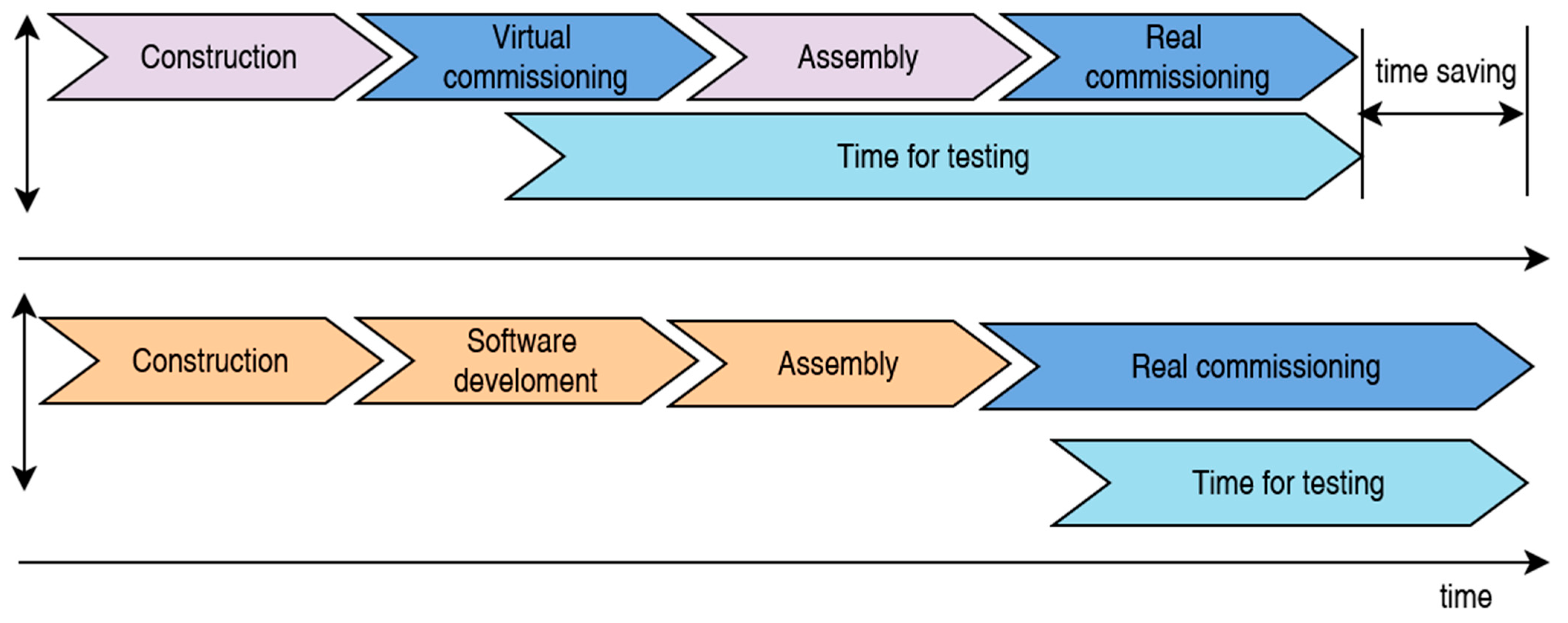
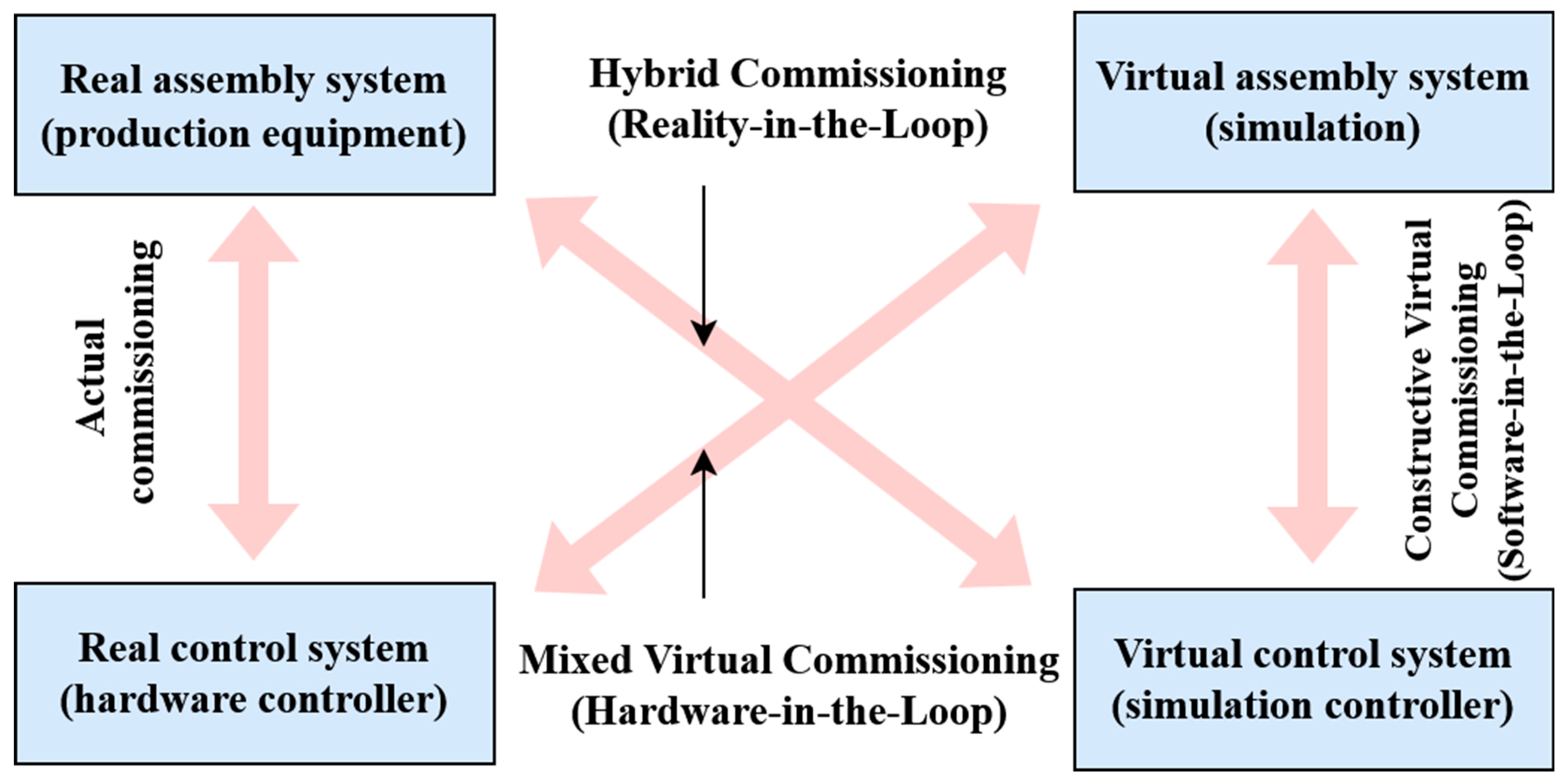
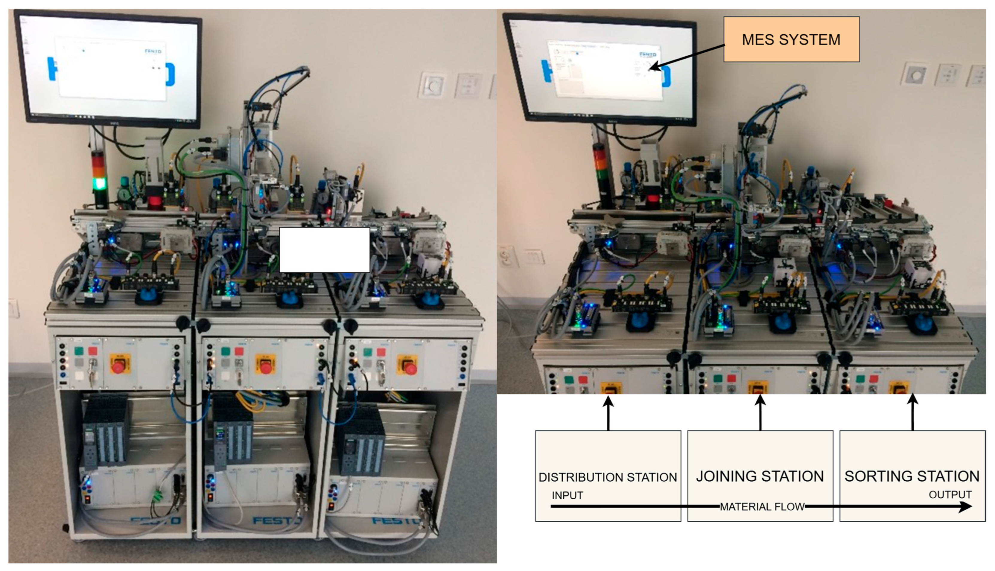
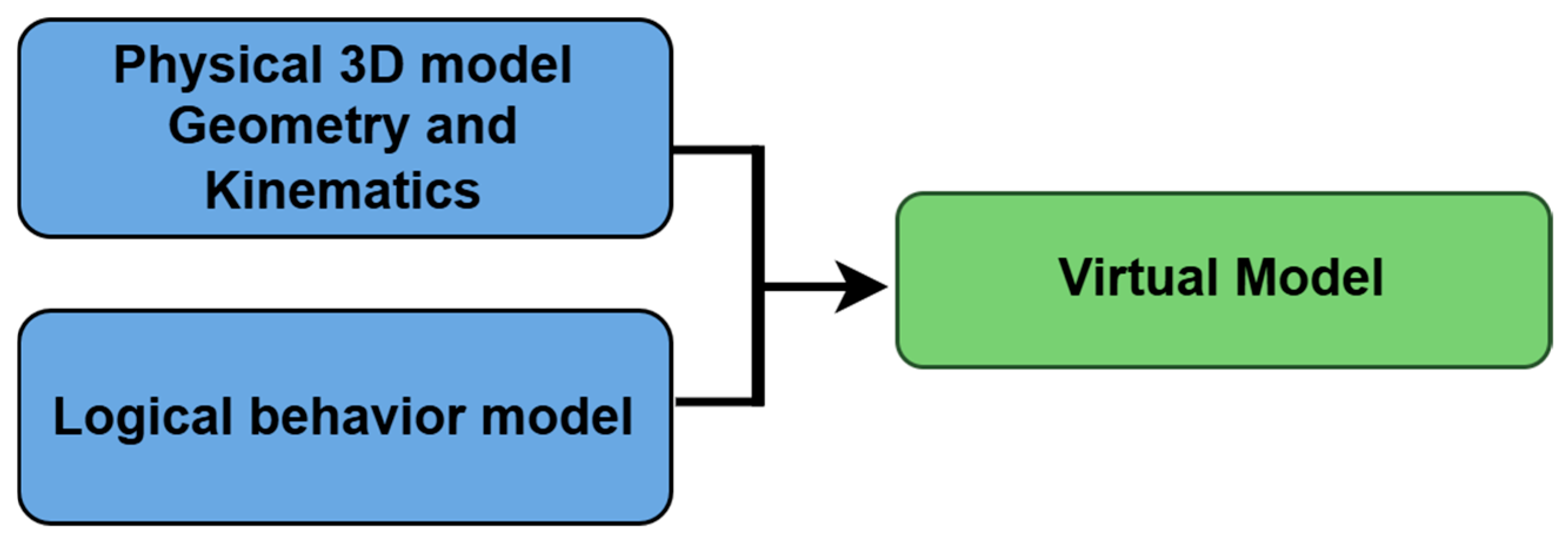
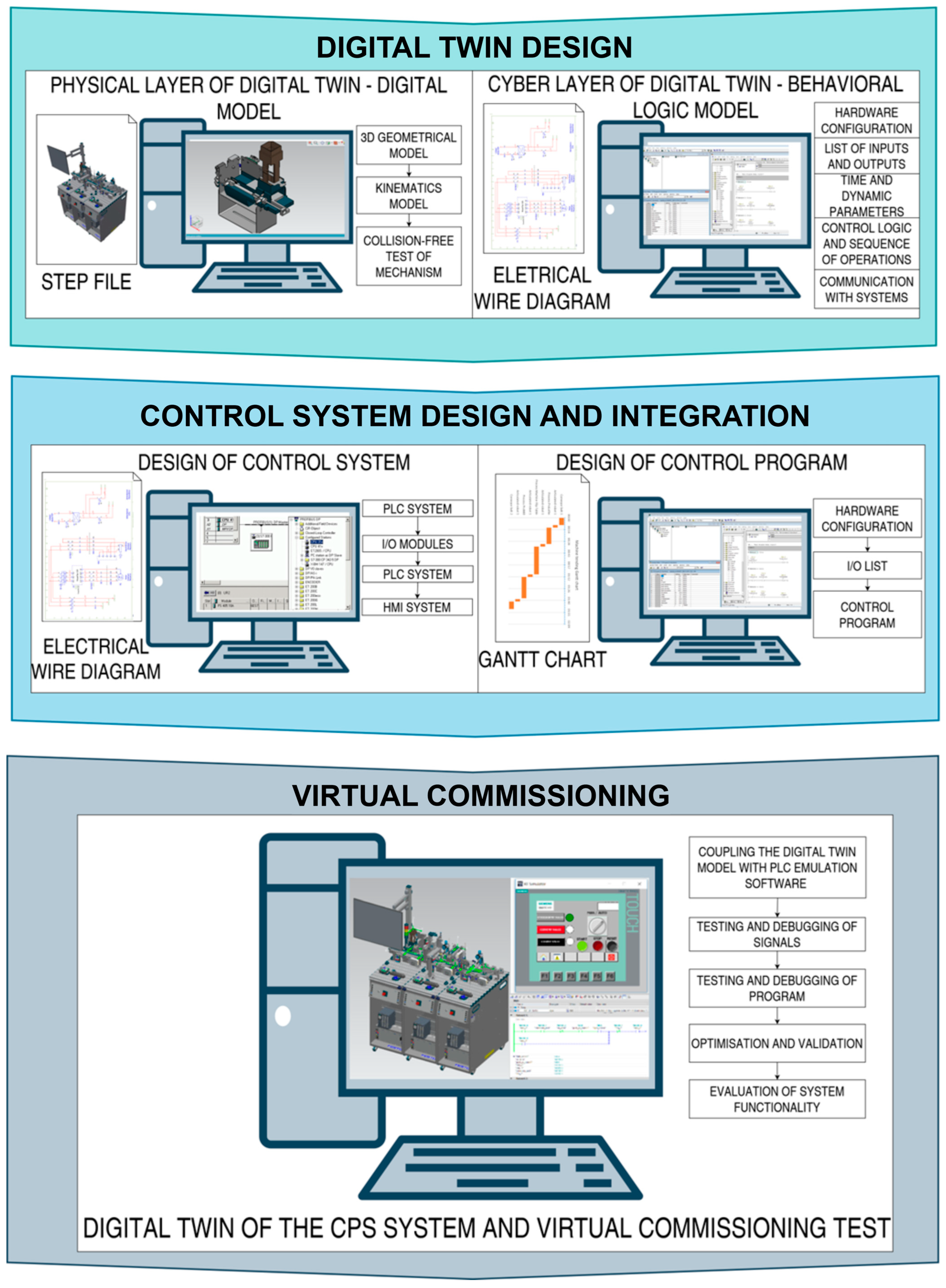
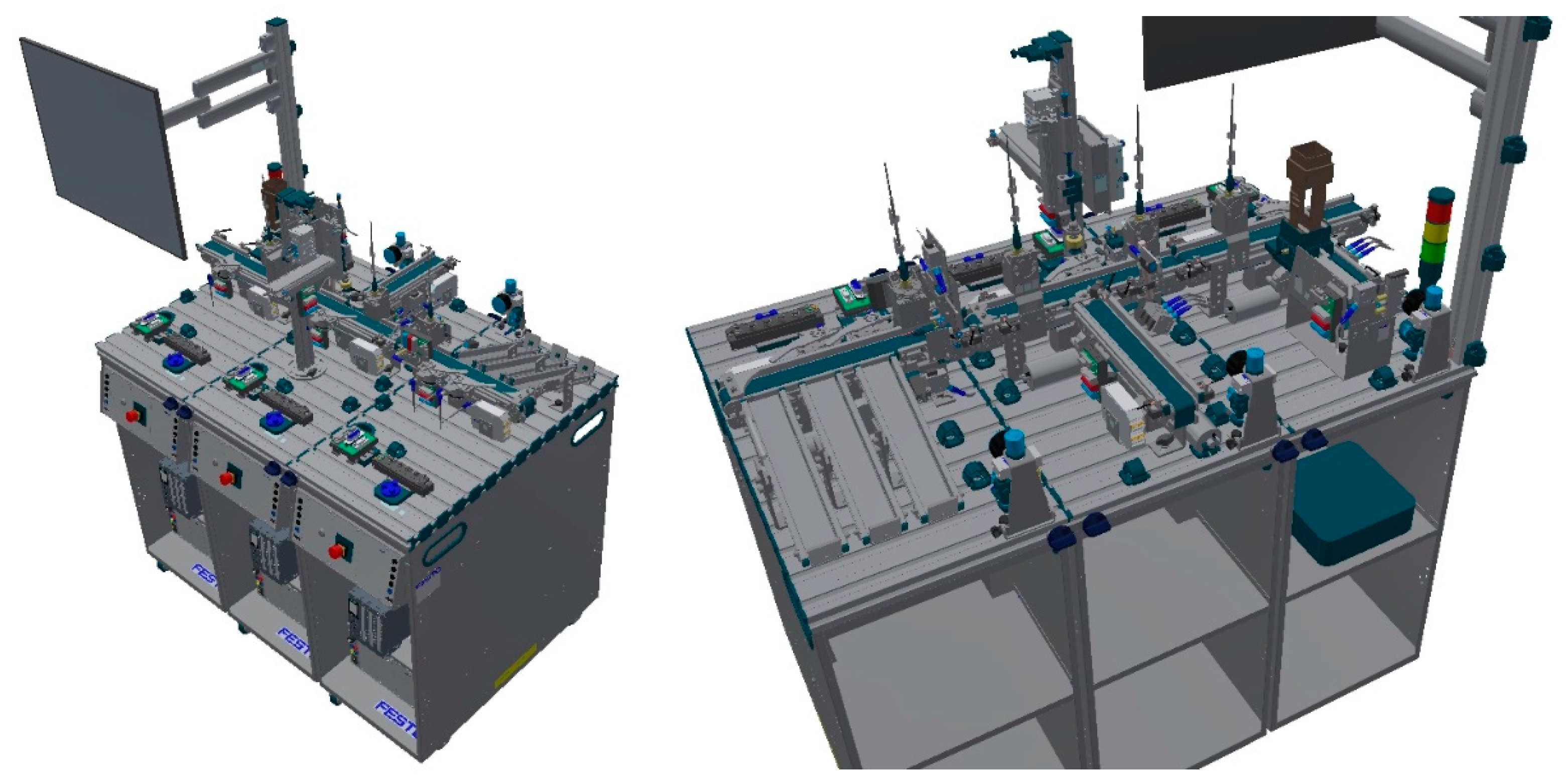
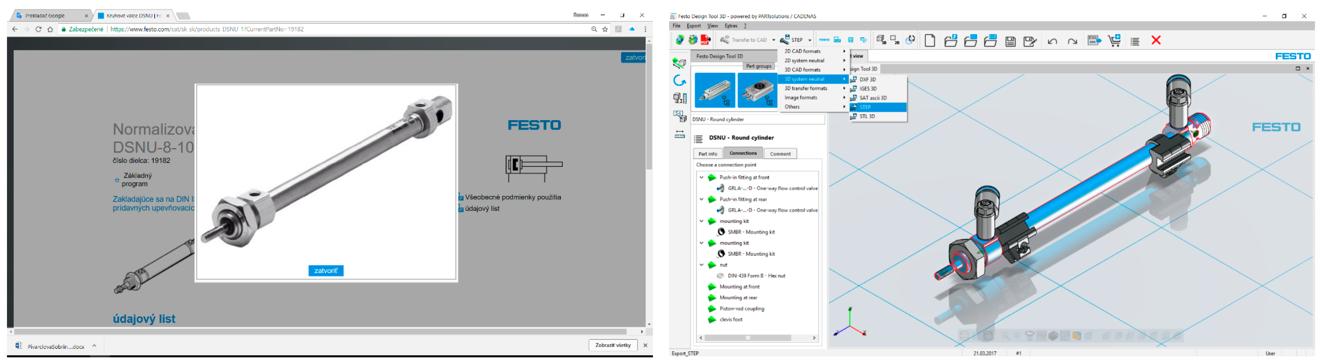
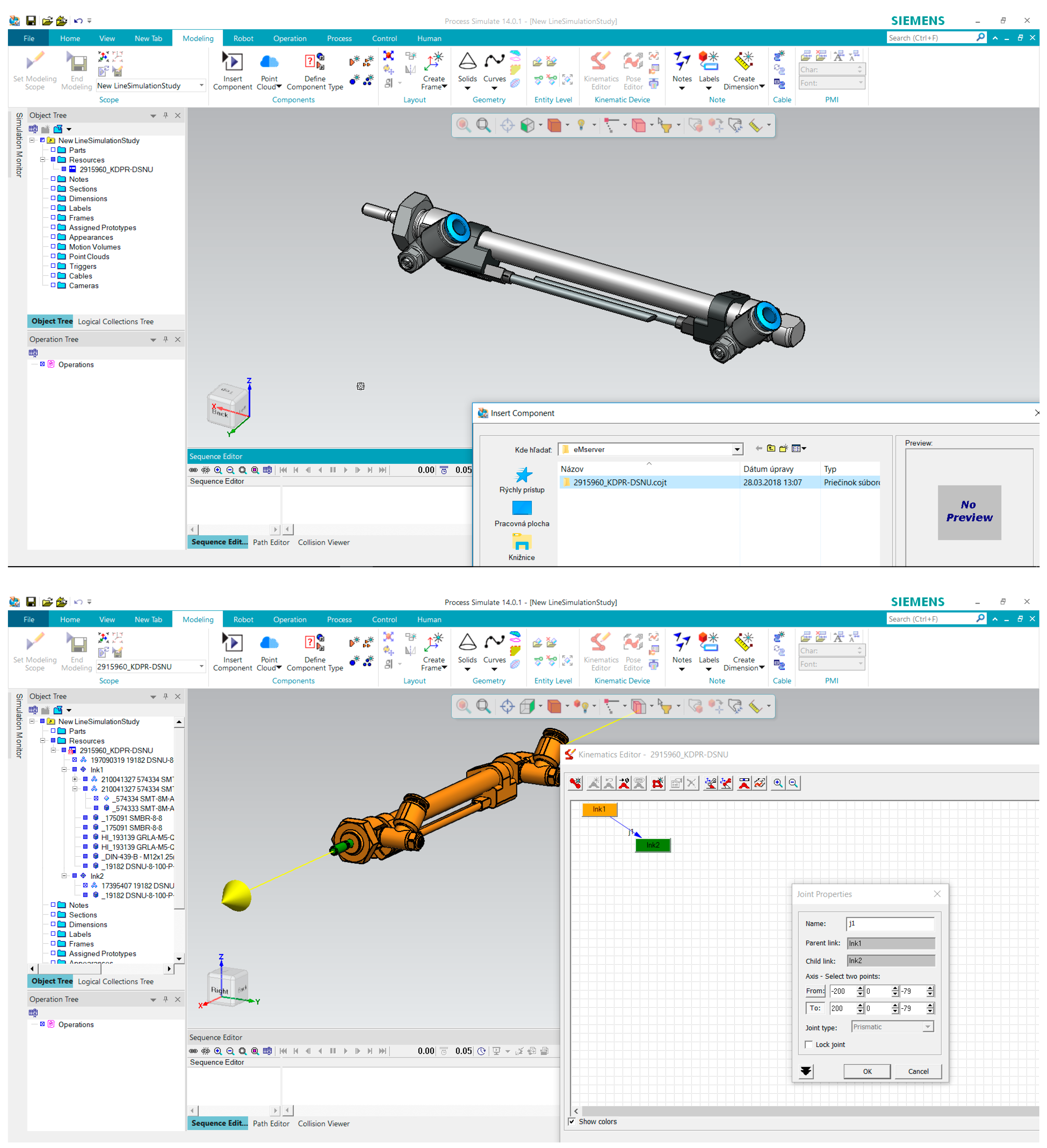
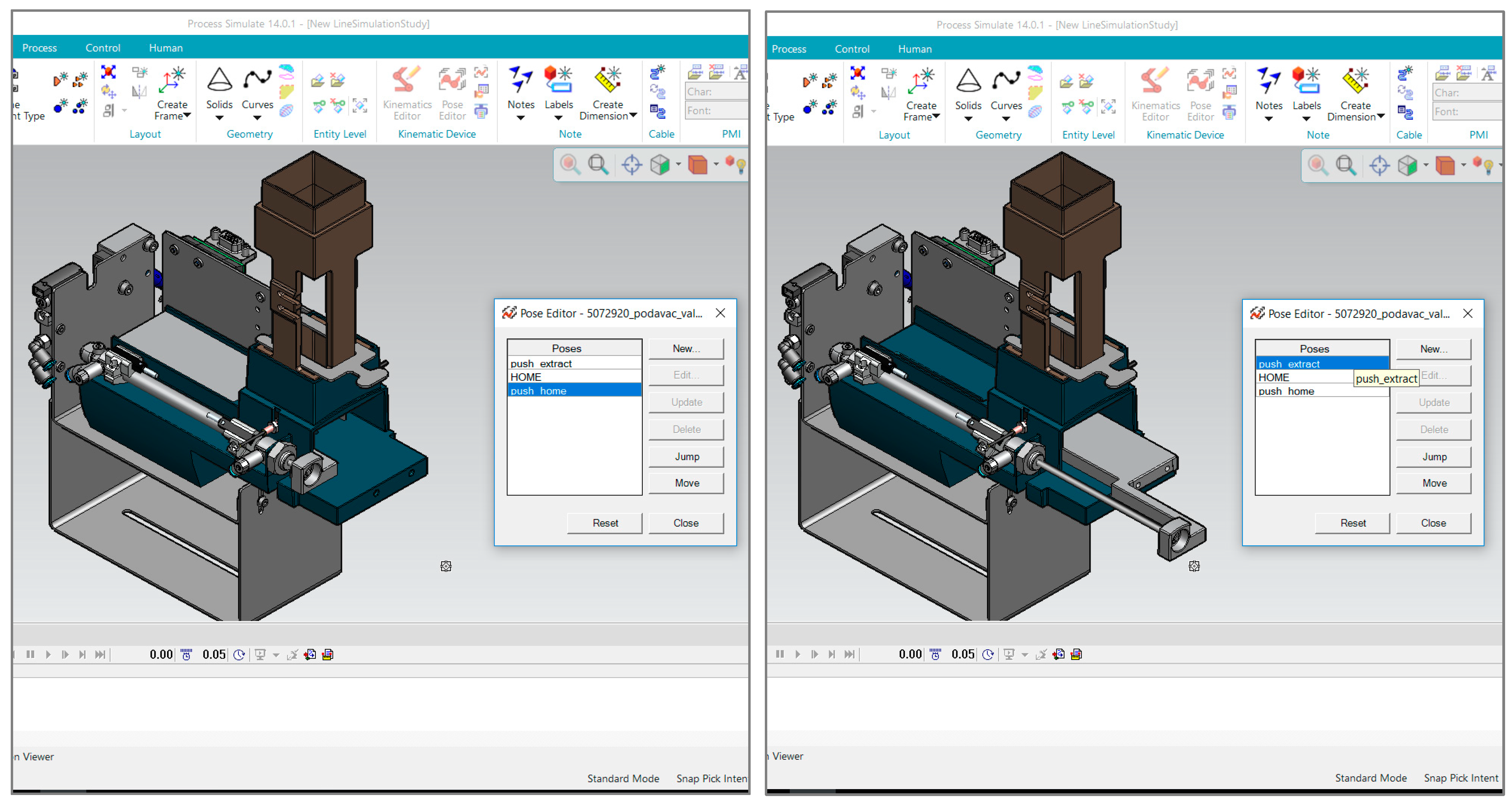
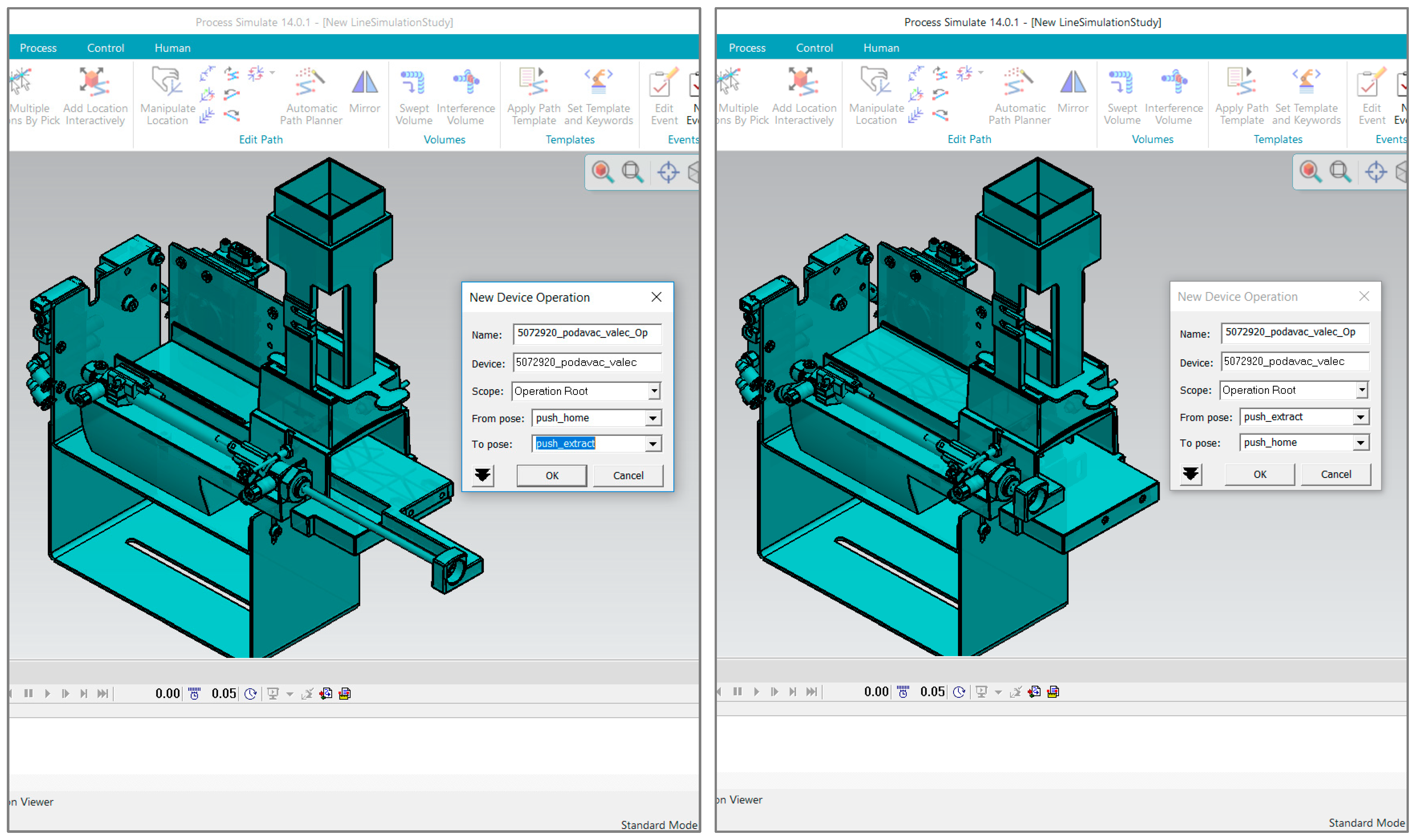
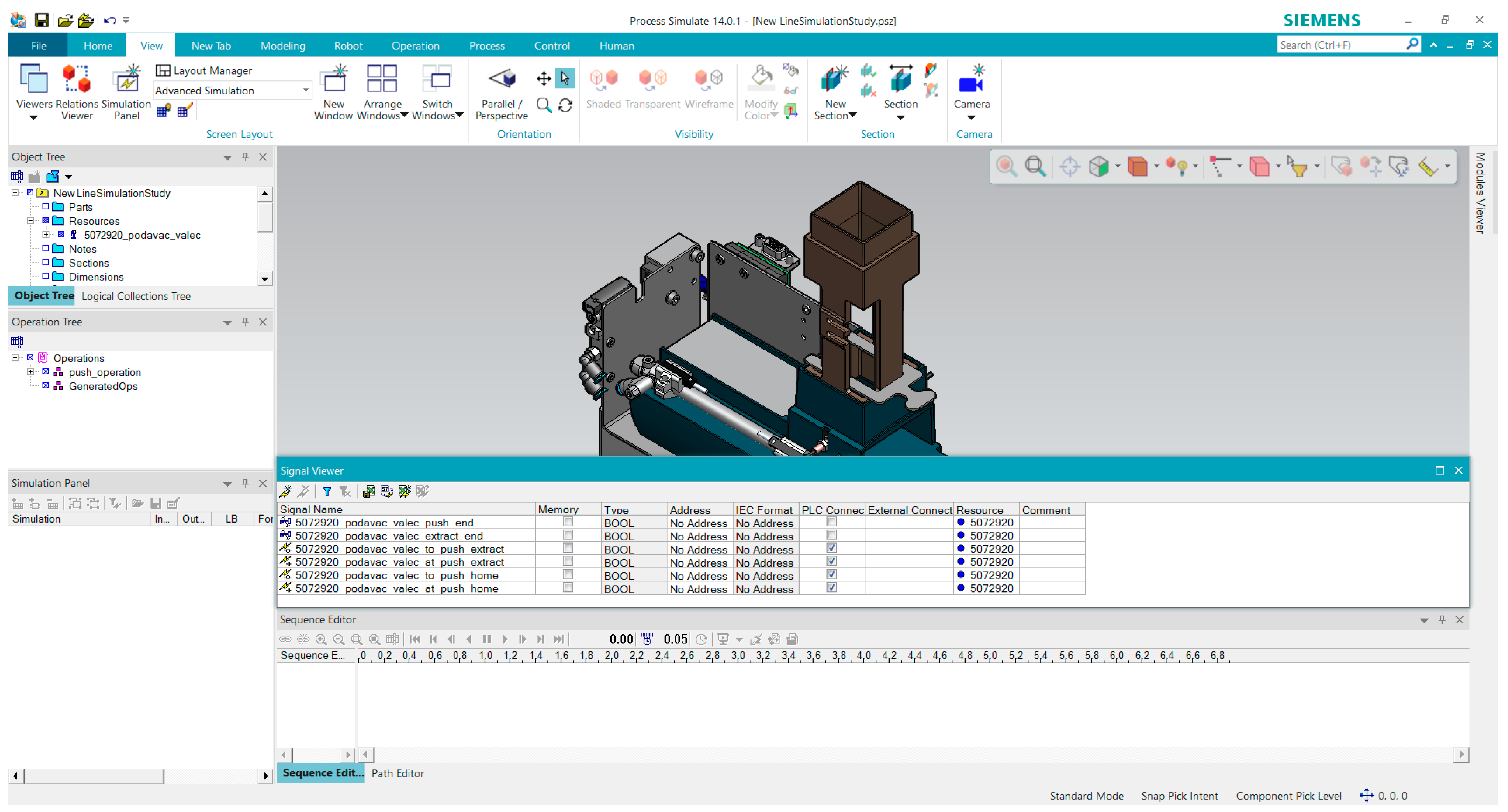
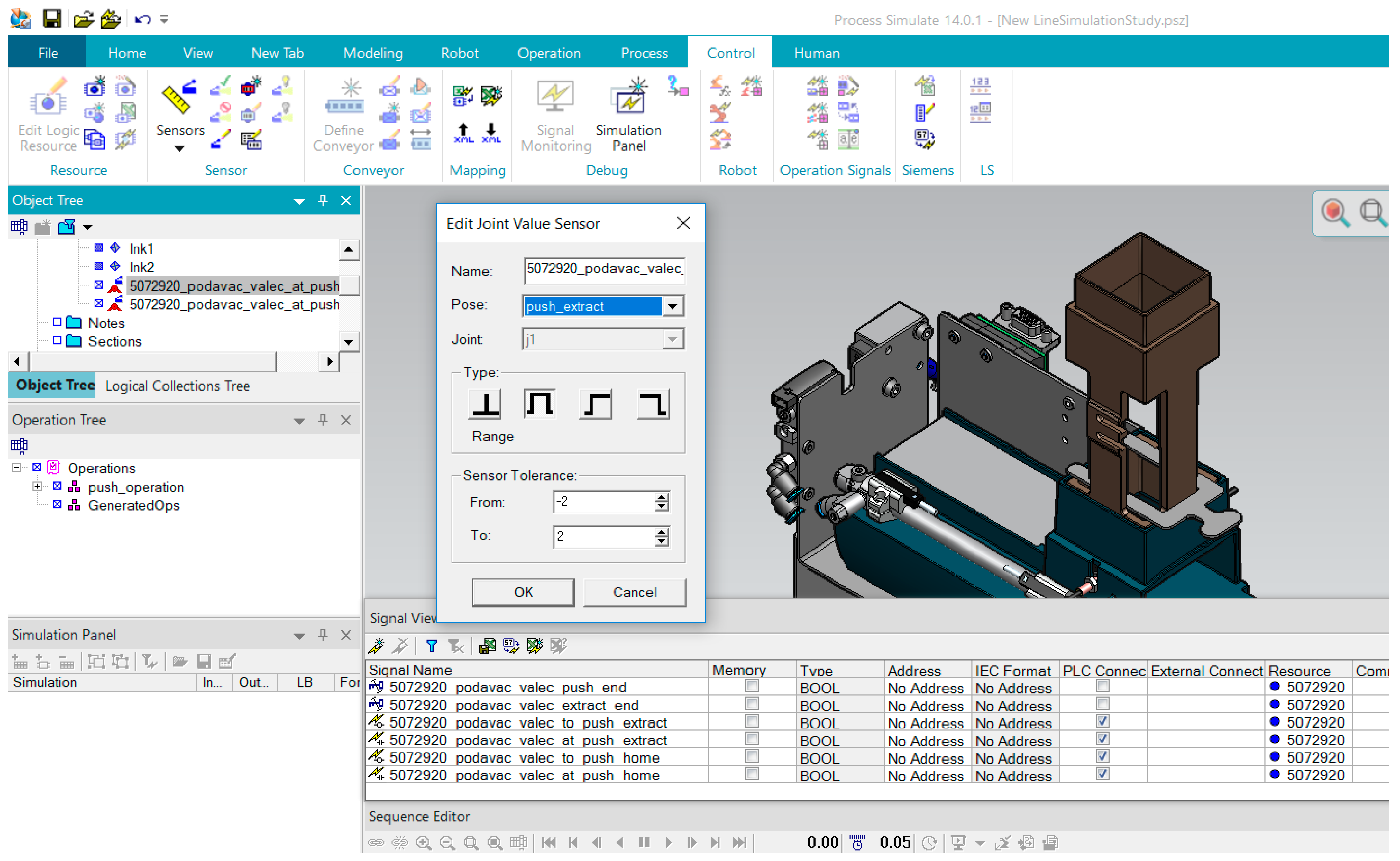
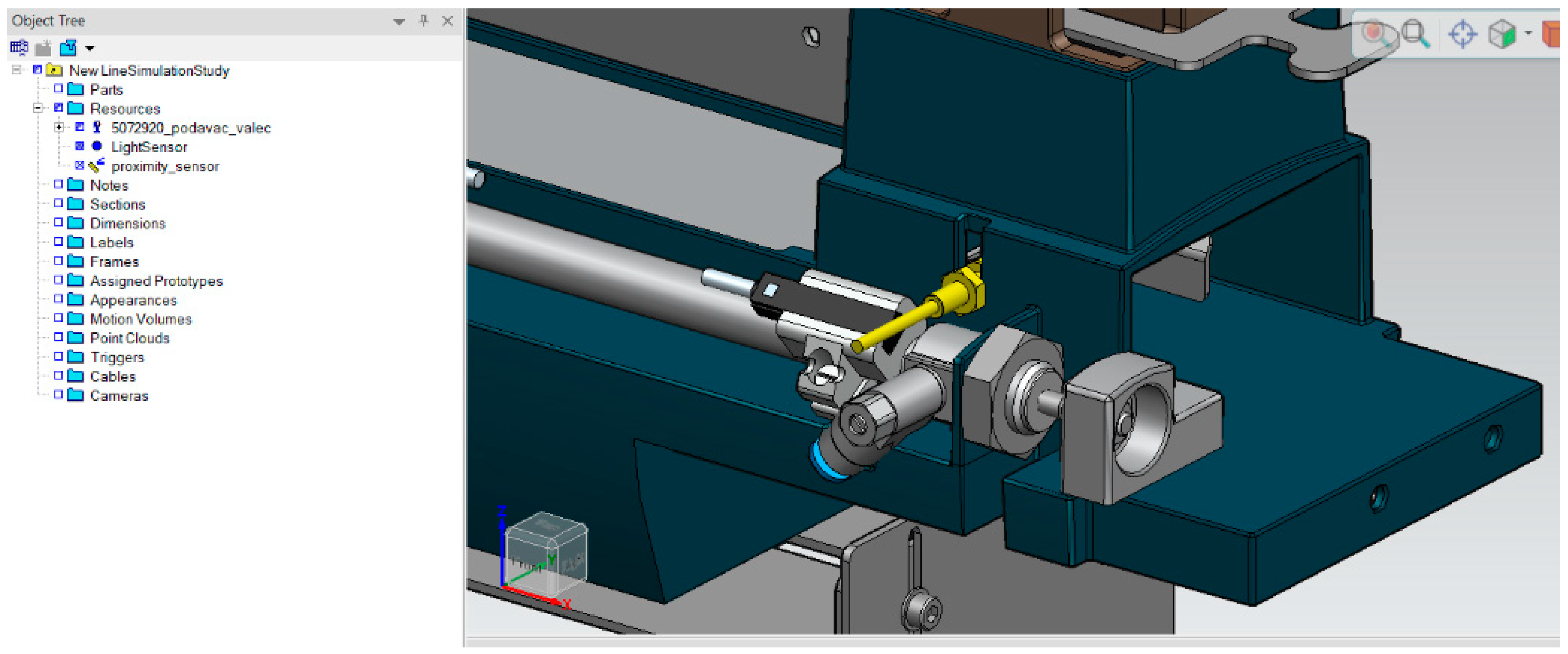
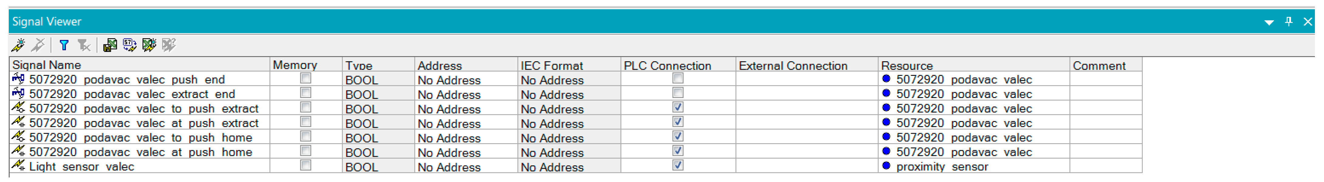
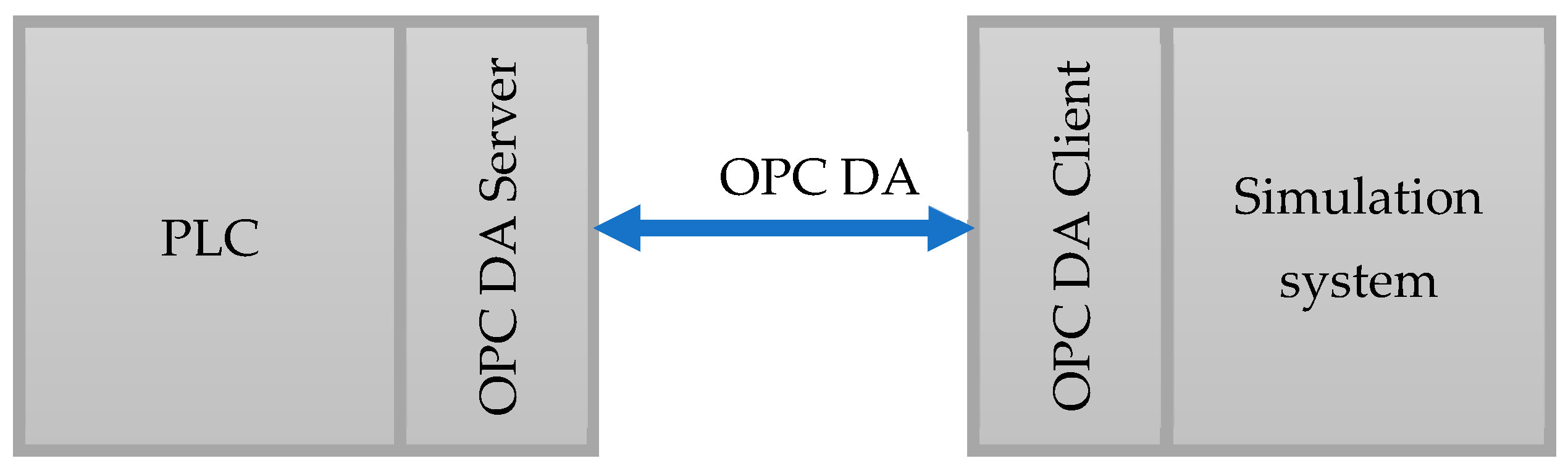
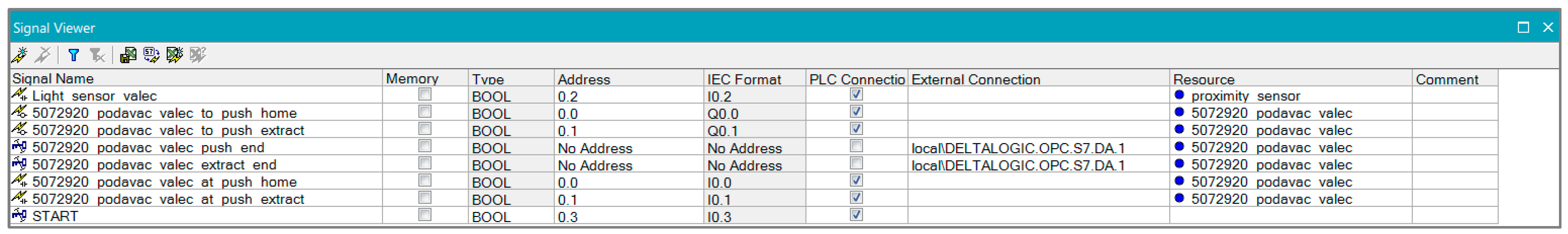
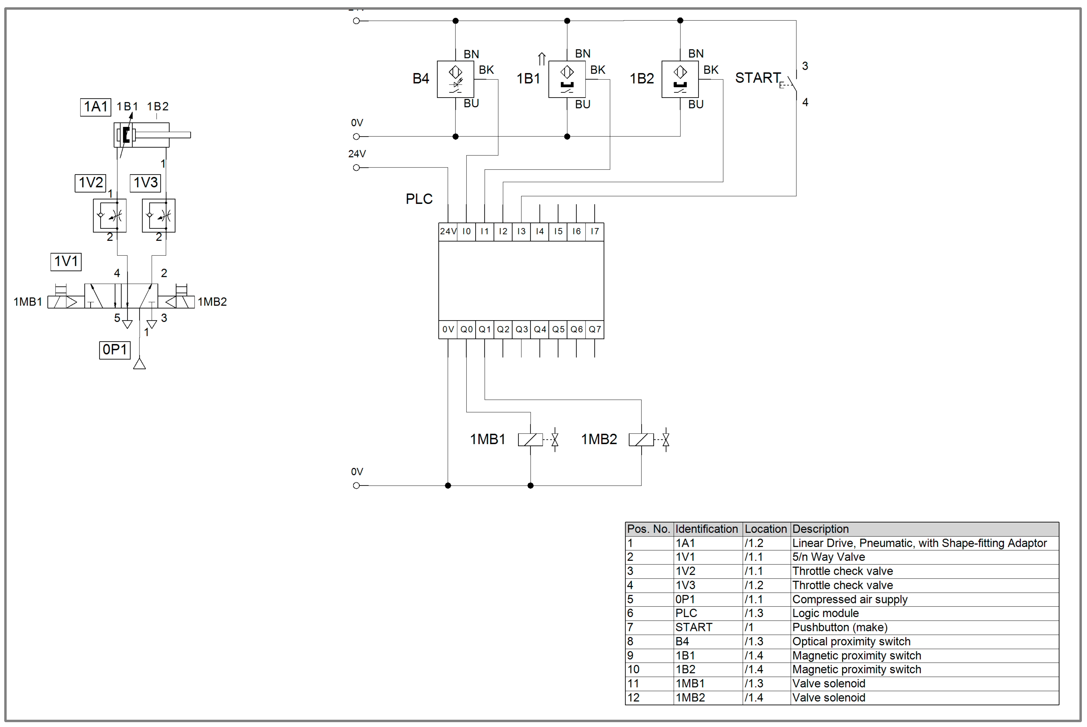
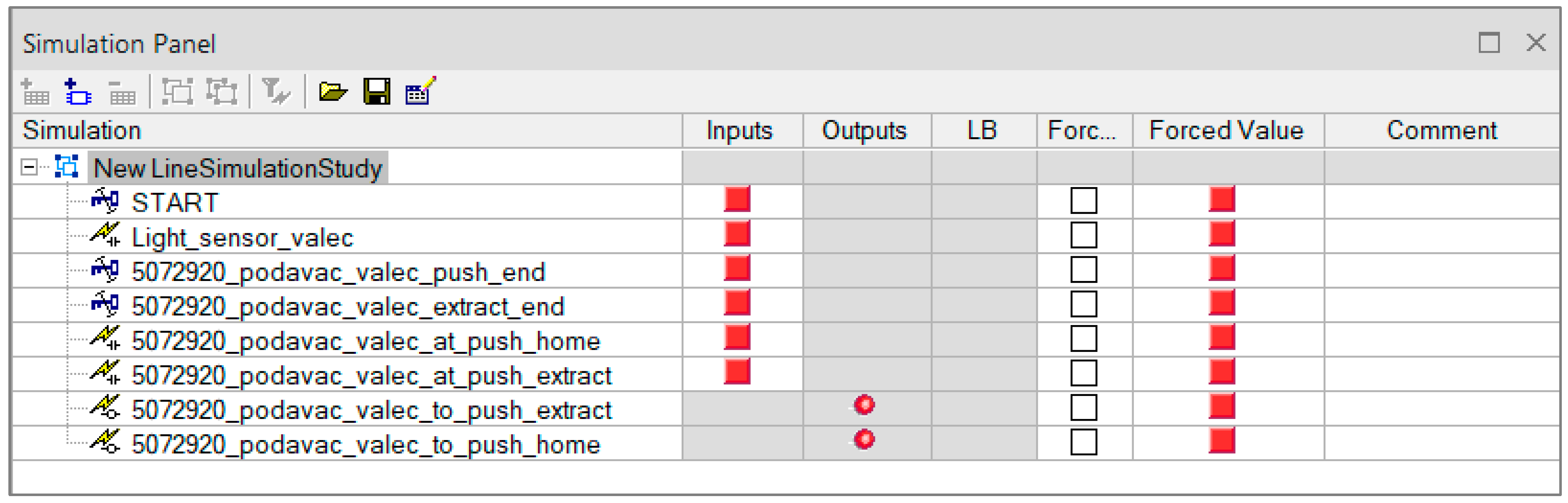

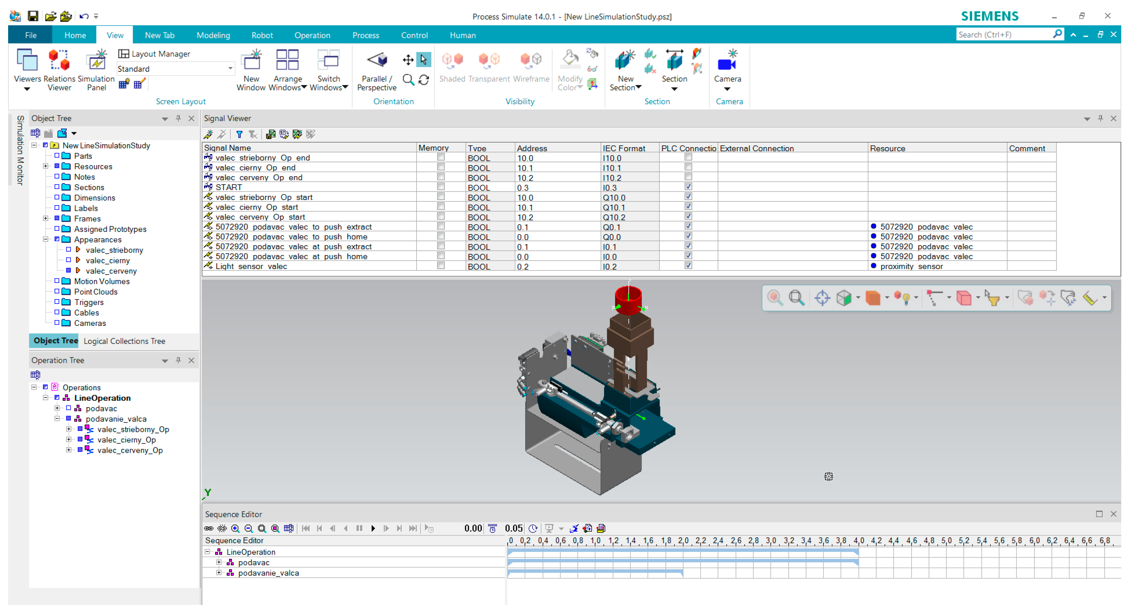
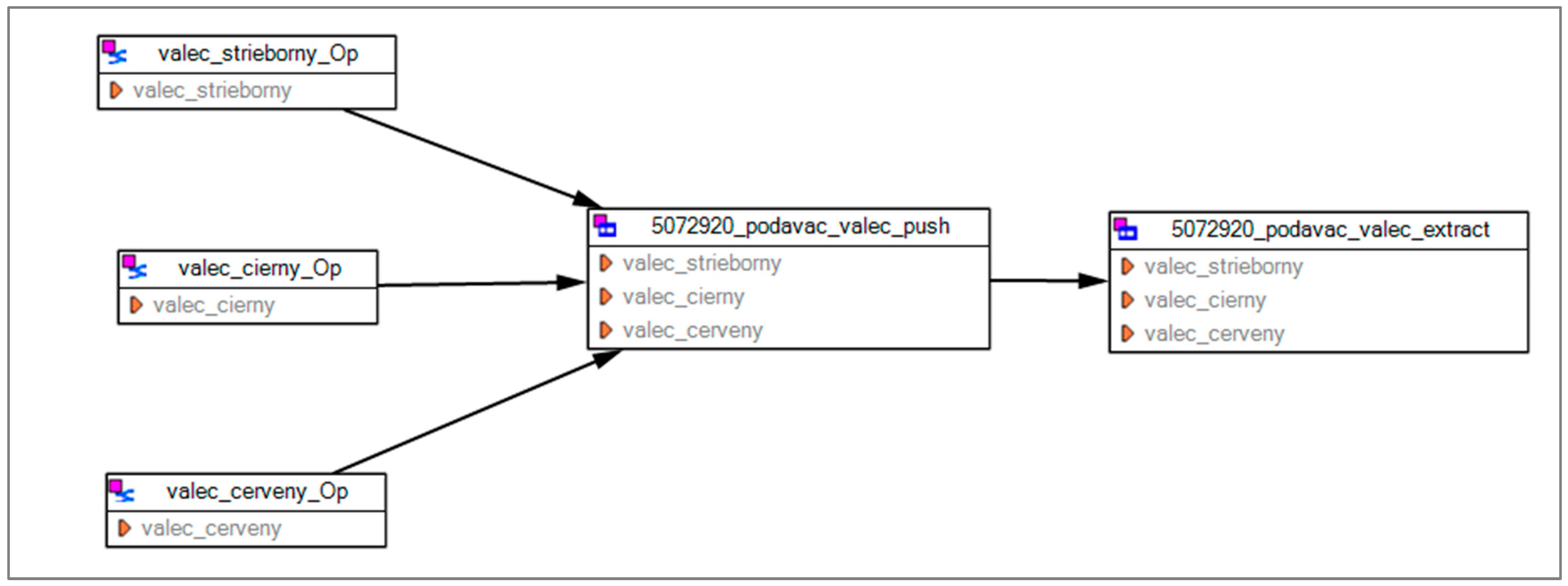
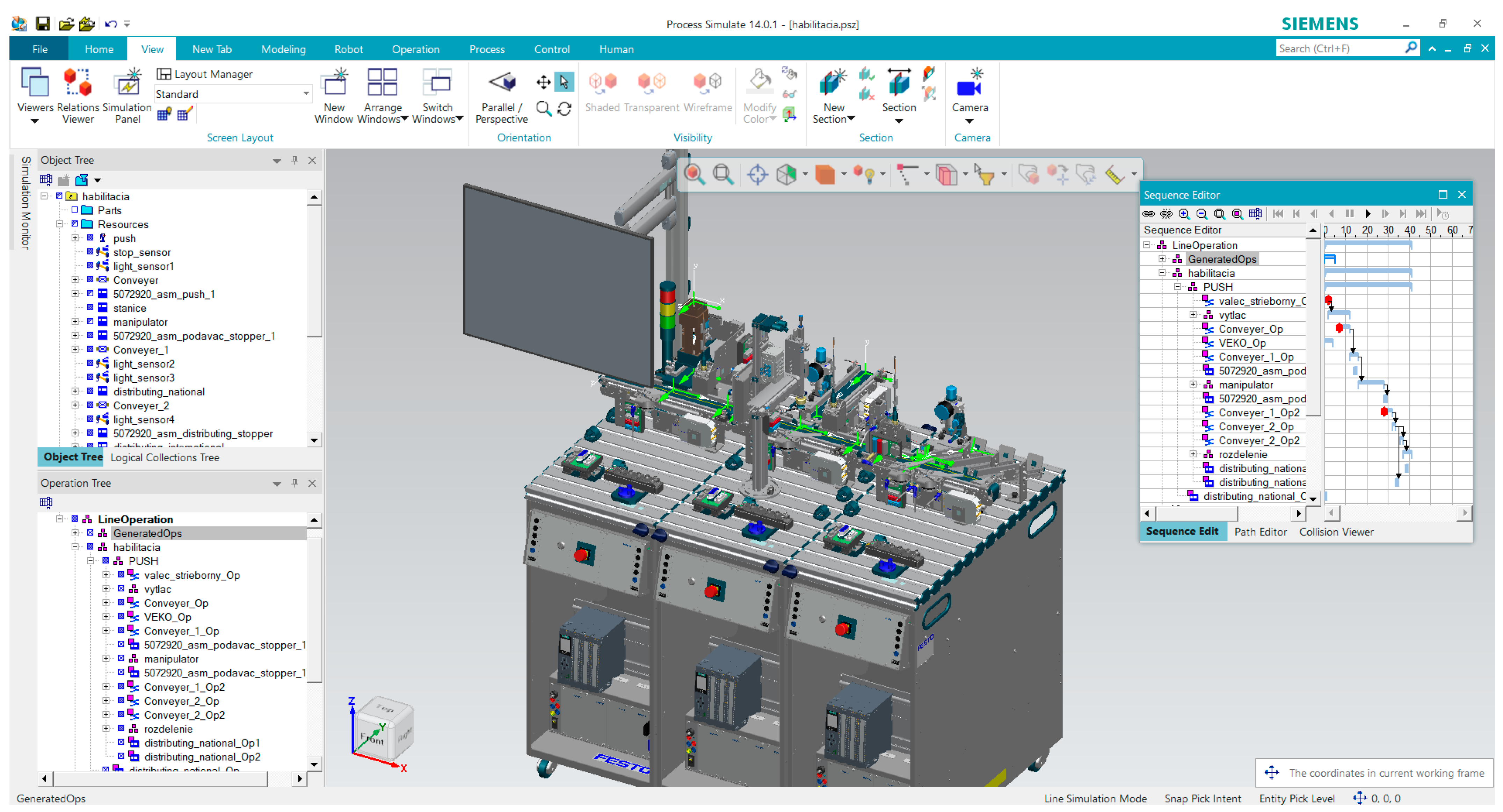
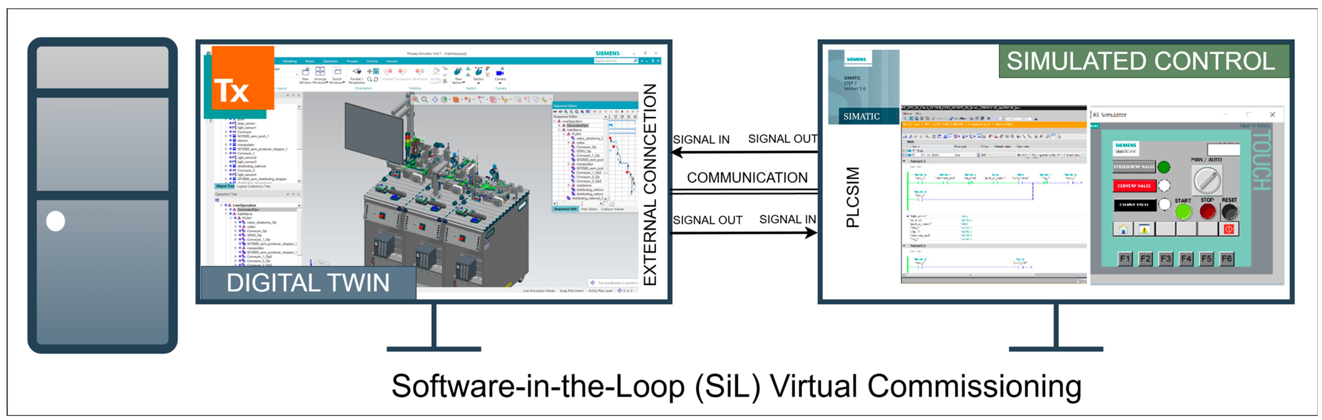
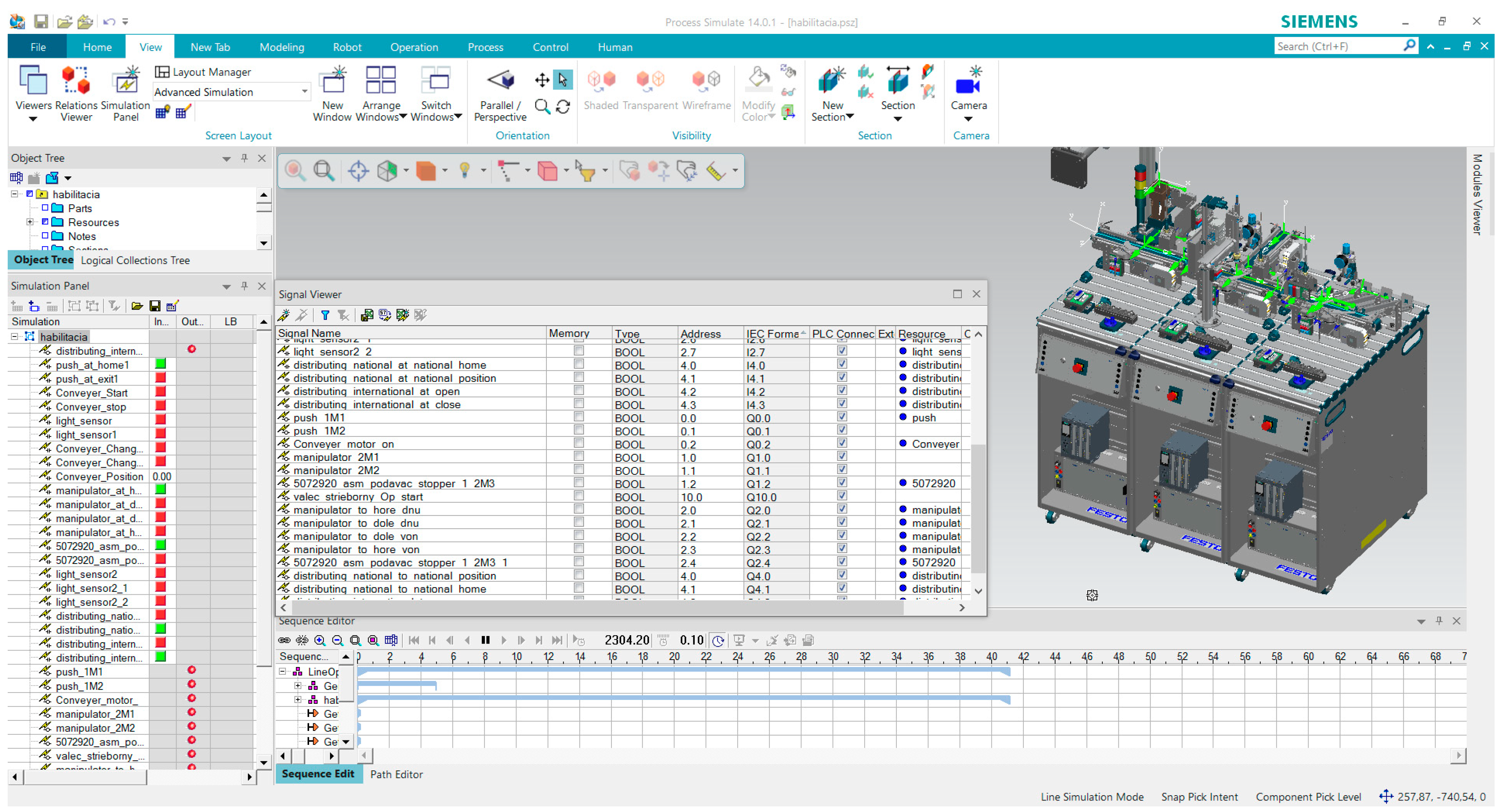
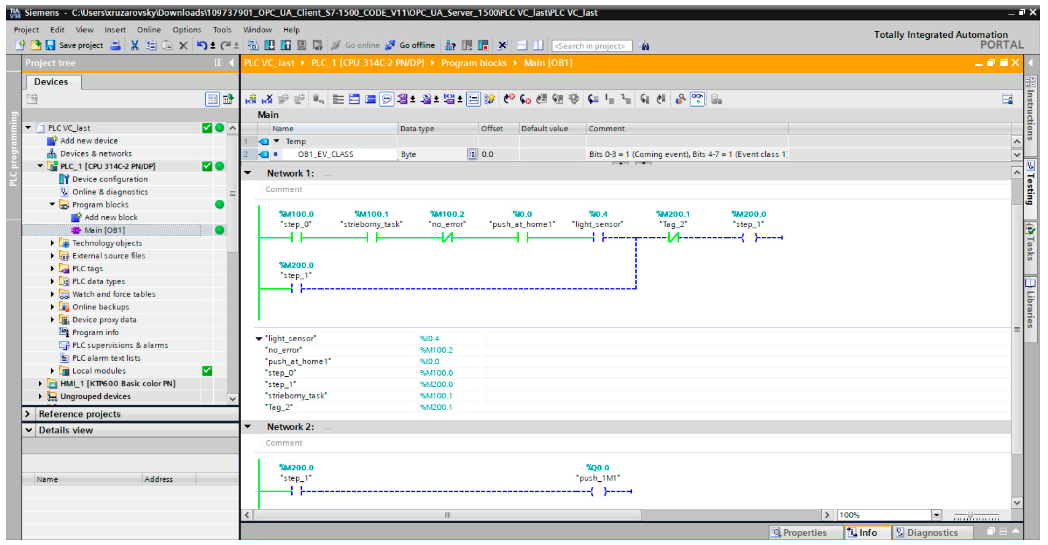
Disclaimer/Publisher’s Note: The statements, opinions and data contained in all publications are solely those of the individual author(s) and contributor(s) and not of MDPI and/or the editor(s). MDPI and/or the editor(s) disclaim responsibility for any injury to people or property resulting from any ideas, methods, instructions or products referred to in the content. |
© 2025 by the authors. Licensee MDPI, Basel, Switzerland. This article is an open access article distributed under the terms and conditions of the Creative Commons Attribution (CC BY) license (https://creativecommons.org/licenses/by/4.0/).