Abstract
Bridge construction equipment (BCE) is crucial for efficiently executing large-scale infrastructure projects, particularly those involving continuous long-span bridges. Current BCE technologies, like the Overhead Movable Scaffolding System (OMSS), are often chosen for their high efficiency and cost-effective reusability. However, the lack of a standardised design framework tailored to Australian conditions complicates the design process, potentially leading to increased inefficiencies and safety concerns. This research project seeks to establish a novel design procedure for BCE, using the OMSS in Australia as a case study. The project adopts parametric design techniques using Rhinoceros (Rhino) 3D and Grasshopper to create a three-dimensional linear model. This model undergoes initial structural optimisation with Karamba3D. Subsequent advanced analyses include linear static design assessments performed in Strand7, a sophisticated finite element analysis software. The evaluation primarily utilises Australian standards to assess performance against various load types and combinations, such as permanent (dead), imposed (live), and wind loads. The structural integrity, including maximum displacement, axial forces, and bending moments, is manually verified against the analysis outcomes. The results confirm that the OMSS model adheres to ultimate and serviceability limit state requirements, affirming the effectiveness of the proposed design procedure for BCE. The research culminates in a design procedure flowchart and further suggests future research directions to refine BCE design methodologies for complex bridge construction scenarios.
1. Introduction
1.1. Problem Specification
From being used for transportation to being part of a water diversion system, bridge structures are widely used in human society. Bridges are used for pedestrians, roads, and railways. The construction of high-speed rail (HSR) has become increasingly popular in recent years. According to the latest Phase II report of the high-speed rail study released by AECOM, the Australian government has plans to build an east coast HSR [1]. This project will be divided into two sections, from Brisbane to Sydney (797 km in 2 h 37 min) and from Sydney to Melbourne (824 km in 2 h 44 min). The total length of these two sections is 1621 km. The construction will commence in 2027 and take around 30 years to complete the whole project. Bridge structures play a significant role in such projects.
Bridge structures are primarily composed of a superstructure and a substructure. The construction materials used in the superstructure include reinforced concrete, prestressed concrete, steel and composite materials, and mass timber. However, the most widely used materials are reinforced concrete and prestressed concrete. The concrete bridge decks can be either cast-in-place or precast. The construction methods include incremental launching, segmental construction, balanced cantilever, precast installation, and a Movable Scaffolding System (MSS). A variety of temporary structures, such as bridge construction equipment (BCE), are used in bridge construction including formwork system, MSS, launching gantry, cofferdam, crane platform, and temporary shoring.
Despite extensive research into bridge construction technologies and the design of temporary structures, universal design guidelines for BCE, particularly for long-span high-speed railway bridge (HSRB) constructions, remain absent. As a cost-effective solution for continuous bridge construction, efforts to develop effective BCE design procedures persist. However, designing BCE for specific bridge projects often results in solutions that are not replicable across other projects. Current standards, heavily influenced by American, Chinese, and European construction codes, do not adequately address the unique challenges of designing BCE for Australian conditions. The lack of standardised guidelines complicates the adaptive application of BCE design across various projects, raises safety concerns, and impedes the development of economically viable solutions.
As the application of BCE expands and their design becomes more complex, the market increasingly demands these systems to be reusable and easily transportable. BCE are transitioning from their traditional role as temporary structures to more permanent structures, elevating their significance in structural design considerations [2]. The lack of consistent design standards in the industry frequently leads to substantial unforeseen costs and increases the risk of structural failures. These issues not only affect cost efficiency but also threaten project safety and timelines [3].
This project proposes a novel design procedure for bridge construction equipment, specifically designed for long-span high-speed railway bridge construction in Australia, employing advanced analysis methods. The focus will be on the Overhead Movable Scaffolding System (OMSS), a typical BCE used in engineering practice, though reinterpreting the design of the MSS model M1-90-S with an Organic Prestressing System (OPS), developed by BERD Company in Portugal, currently used in constructing bridge spans of up to 90 m [4]. The redesigned numerical model was simulated under various load cases to evaluate its capacity for constructing bridges spanning over 100 m and to establish a definitive roadmap for designing an OMSS for the construction of long-span, heavy bridge decks. This research complied with Australian standards throughout and bridges the gap between design codes and engineering practice.
1.2. Objectives
The reimagined OMSS structural system was modelled parametrically in Grasshopper (Build 1.0.0008), a visual programming tool based on Rhinoceros 3D Version 8 (Rhino 8), mainly used for parametric design and algorithm modelling. Powered by Karamba3D (version 3.1.40918.0), a structural analysis plug-in in Grasshopper, it enables real-time finite element analysis (FEA). The advanced analysis of the reimagined OMSS structural system was conducted using the FEA method. This project utilised Strand7 (version R3.1.3), an FEA software for structural analysis, complemented by the manual verification of the analysis results. The analysis refers to the relevant Australian standards. The bridge deck design was reviewed under AS 5100.1:2017 [5]. The numerical model was analysed under Ultimate and serviceability limit states (ULSs and SLSs) according to AS/NZS 1170.0:2002 for structural design actions [6]. The analysis considers various combinations of actions, including permanent (dead), imposed (live), and wind actions. The member capacity and global deformation of the entire system were examined using the linear static solvers of Strand7. The member sizing process follows AS 4100:2020 for steel structures, based on the results obtained in the linear static analysis [7]. Subsequent examinations focused on crucial parameters, including maximum displacement, principal axial forces, and critical bending moments to evaluate the capacity and feasibility of the proposed model. A new design procedure based on the OMSS design with long-span bridge construction ability is demonstrated. Potential directions for future research are suggested. The objectives of this project are outlined as follows:
- Employ the parametric design technique through Rhino 8 with Grasshopper to create the three-dimensional numerical model of the OMSS and conduct initial structural optimisation on critical load-bearing frames to enhance design efficiency using the Karamba3D plug-in.
- Conduct a preliminary design of the bridge box girder deck section, operation stages, and site conditions.
- Perform linear static design analysis in Strand7 while applying appropriate load combinations (including permanent (dead), imposed (live), wind actions) as defined in AS/NZS 1170.0:2002.
- Obtain crucial parameters (including maximum displacement, principal axial forces, critical bending moments), verify them manually, and conduct material selection and member sizing according to AS 4100:2020.
- Propose a flowchart describing the new design procedure and possible future research directions.
1.3. Scope
Given the complexity of the problem, the proposed design procedure and the results of the numerical analysis rely solely on the redesigned structural systems, with all research data derived from finite element simulations. Additionally, only the concrete casting stage of the OMSS was simulated and analysed numerically under various simplified scenarios that do not account for the kinematic behaviours of advancement between execution spans. The bearing capacity of the supports (brackets) and piers is assumed to be sufficient, and the extension and movement of the supports are not covered in this paper. The span of the erected bridge deck is assumed to be straight, meaning the minimum curvature radius and gradient are both zero. The manufacturing and installation of metal structures, including surface treatments, welding, bolted connections, and camber design, are not discussed, and all structural components are assumed to be in an ideal state. Furthermore, electrical devices, hydraulic cylinders, and other auxiliary equipment are excluded from this project. Fatigue failure, temperature effect, geometric imperfections, and equipment reuse only serve as references to guide the design of numerical elements and joints. Moreover, only a simplified analysis of dynamic wind loads was conducted, as rigorous design analysis would require further studies using Computational Fluid Dynamics (CFD) tools and wind tunnel experiments, which are beyond the scope of this project. Such aspects should be addressed in future studies.
2. Literature Review
2.1. Development of Movable Scaffolding System with an Organic Prestressing System
The evolution of bridge construction materials has progressed from stone to reinforced concrete, leading the advancement of construction methods. Furthermore, the innovation of prestressing technology has realised longer bridge deck constructions with continuous spans, aiming to reduce construction costs and duration, which inspired the development of movable equipment. As introduced by Póvoas [8], the equipment can be roughly divided into two groups depending on the construction forms, which are prefabricated or cast in situ decks or segments. To build cast in situ bridge decks, there are three groups of equipment including movable formwork tables, Movable Scaffolding Systems (MSSs), and formwork travellers [8].
The span-by-span method, exemplified by the MSS, changes bridge construction by enabling incremental launching and the successive displacement construction method for both cast in situ and prefabricated bridge decks [9]. The MSS, first introduced in 1959, offers economic advantages for viaducts and railway bridge construction by reducing auxiliary equipment and ground works [10]. It employs robust steel structures, hydraulic or rotary traction systems, and prefabricated decks for efficient assembly and movement. Prefabricated elements, connected via prestressing or epoxy resin, allow for spans of up to 80 m [9]. Such scaffolding systems can be classified as overhead or underslung depending on the position related to the bridge decks, adapting varying geometries [8]. The primary structural element of the MSS is the launching girders, featuring solid or trussed webs with different strength and flexibility [9]. The modular nature of these systems facilitates efficient reuse and transportation across projects, highlighting their role in modern bridge construction [10]. In addition, the application of an OPS in the MSS represents an advancement for managing higher loads and spans in bridge construction, particularly beneficial for HSRBs. Although it introduces complexities such as fatigue and response delays, the cost-to-benefit ratio remains favourable, underscoring the evolving nature of bridge construction technologies [9].
The Overhead Movable Scaffolding System (OMSS) model M1-90-S developed by BERD Company in Portugal will be redesigned based on the Australian building codes in this project. This bridge construction equipment (BCE) is initiated after the innovation of Organic Prestressing System (OPS) technology led by Pedro Pacheco in the 1994, as part of the research and development program supported by the Faculty of Engineering, University of Porto, Portugal. The initial research on this technique was in Portuguese [9,11]. The innovation of organic prestressing is inspired by the structural system in nature. It can be considered an effector system (known as an “artificial muscle” or active control system) that can modify the strength of a structure and be applied to resist quasi-static loading [12]. Pacheco and Adão da Fonseca [13] outlined adaptive prestressing technology that increases structural slenderness and lightness and reduces prestressing losses by 50% and suggested future research on deformations, vibrations, and fatigue under high live-load/dead-load ratios. Fatigue failure should be monitored and analysed for structure under vibrations [14].
MSSs were chosen as the first prototype to apply to OPSs due to their high live-load/dead-load ratio, with a scaled model of a trussed girder tested for structural feasibility [9]. An OPS uses sensors like strain gauges and accelerometers to gather structural data, which are processed by explicit controllers using pre-embedded algorithms to adaptively apply prestress via hydraulic actuators, successfully controlling mid-span girder deflection during simulated concrete casting [9]. Numerical analysis was used to assist the design of the physical experiment and to set up a comparison, where the results show that the mid-span deflection was reduced about 90% [15]. This research identified future areas for enhancing the MSS with an OPS, focusing on kinematic challenges like actuator placement, monitoring multi-span behaviour and thermal stability, and designing deviation saddles to minimise cable friction and wear [9].
The outcomes of this experiment encourage the application of the OPS in real engineering practices. Thus, to accommodate the massive demands for constructing high-speed rail (HSR) bridges and considering economic factors, they also explored using the OPS to reinforce existing traditional MSSs [16]. This approach was aimed at adapting them for longer spans and heavier bridge construction, rather than spending more of the budget on new construction equipment. Subsequently, in 2007, the first full-scale MSS with an OPS was demonstrated, achieving over 90% reduction in mid-span deflection, 30% less steel usage, increased load capacity, and safety through sensor monitoring, while also enhancing scaffold versatility, adaptability, transportability, and storage efficiency [17].
Initially focused on the underslung MSS type, Pacheco et al. [18] shifted to the “bowstring” OMSS prototype to increase span and kinematic capabilities, featuring an arched upper chord and an OPS-controlled lower chord that limits mid-span deflection to less than L/2000 during concrete casting. This advanced system reduces equipment weight by 25–30%, acquisition costs by 15%, and operational costs by 10–20%, making it suitable for constructing heavier HSR bridge decks. In applying the OPS in the MSS, there can be a significant reduction (about 6%) in steel and the energy consumption contributing to the carbon footprint control and satisfying the general sustainability goals [19]. The successful application of this equipment in constructing bridge decks with spans of 70 to 90 m led to analysis and design recommendations for both bridges and large MSSs (LMSSs) [20]. The arched upper chord in the temporary modular bridge (LMB120) design reduced structural weight by 18%, increased stiffness by 26%, and maintained lower stress levels compared to traditional truss bridges [21].
To ensure the robustness of the proposed MSS model, Pacheco et al. [22] developed a methodology that includes experimental tests, checklists, and software integration for validating the operational effectiveness and structural integrity of systems, which could be enhanced with a self-diagnosis function. Pacheco et al. [23] specifically emphasised that the OPS can significantly boost productivity in bridge projects, as the system could allow lighter construction designs and ensure continuous monitoring, leading to faster construction cycles and improved safety so that the construction delays caused by accidents could be minimised. The development of an overhead MSS with the OPS underscores the importance of addressing fatigue through damage-tolerant methods, stringent material selection, quality control, and robust maintenance plans to enhance durability and safety over extended service periods [2].
MSS M1-90-S was developed based on the sufficient previous research mentioned above, and this model will be the benchmark of this project [4]. With this model, the maximum construction span was extended to 90 m and the corresponding construction cycle was also generated to ensure the largest building efficiency [24]. This construction equipment was further discussed in terms of its efficiency to satisfy the time, economic, and sustainability requirements through its application in the Ankara–Sivas high-speed railway construction in Turkey and was analysed based on its construction processes for continuous concrete bridges [25]. In the implementation of the OPS, its adaptive load control feature was guaranteed through the sensitivity of the integrated sensor systems. The feasibility of such a system for monitoring the wind and vibrations of the structural system was also examined [26]. The robustness of the monitoring system was confirmed in a project with in situ prestressed concrete decks up to 70 m, where wind loads and member stresses aligned with design predictions, and dynamic excitation was analysed, showcasing the advancements in construction information technologies that enable the automation and self-diagnosis of structural health [27].
Based on previous research, BCE is recognised as a significant component in the bridge construction industry. The MSS with an OPS, as the OMSS precedent in this project, has demonstrated the capability to construct bridges with longer spans and heavier decks. However, the design of such systems has primarily followed Portuguese and European construction codes. The design procedure of such a complicated structure is still unclear. Thus, this literature review reveals a gap in designing for engineering practices and accommodating the system within the Australian context.
2.2. Existing Code-Based Design Guidelines for Bridge Construction Equipment
BCE is widely applied in the infrastructure construction projects in the world. A series of studies on the design guidelines of BCE can be found in various books and articles [28,29,30,31]. Unlike typical permanent designs, the general loading scenarios for BCE, like the OMSS, are comparable to temporary structures, which are predictable and measurable, including dynamic effects, which affect load factors [32]. Careful considerations of instability effects, wet concrete density, lateral impacts, and wind load variation are required. Especially for the wind loads, it is significant to obtain detailed monitoring data and analysis results from the actual working environment of the equipment. Seismic effects are generally not considered unless the area is highly active. The typical bridge superstructure type for spans larger than 60 m is box girder [33]. The positions of construction joints are determined based on the location with the minimum bending moment, which typically occurs at L/5 of the span length. This is considered in the MSS model proposed in this project. Moreover, studies have also mentioned the challenges of applying conventional steel design codes to BCE because the equipment has a more extreme loading scenario with the influence of actual operational activities, such as the location and alignment of supports. The internal force due to movement, which is concentrated at the connection, should also be assessed in detail. In applying standards from cranes and heavy lifting equipment and adhering to permanent steel structure standards, the BCE design can ensure safety and reliability during bridge construction operations [34].
In Australia, there is a lack of mandatory design standards specifically addressing bridge construction structures. The Australian Building Codes Board [35] offered recommended guidelines for temporary structure design, which explicitly state that its guidance is advisory only, and these standards do not include specific design requirements for bridge construction. The National Construction Code [36] included regional deemed-to-satisfy provisions for Tasmania and New South Wales; however, these provisions are primarily limited to temporary structures for entertainment venues and do not cover the temporary structure for bridge construction. Moreover, the NSW Parliamentary Counsel [37] nominated design guidelines about temporary use structures, requiring compliance with the AS/NZS 1170 standard series for permanent, imposed, and wind actions without consideration for seismic effects or specific designs for construction structures. However, with respect to its complicated nature of usage, design standards and recommendations for permanent, temporary, and crane structures are required to be referenced, and an integrated resolution needs to be produced. Australian standards such as the AS 1418 series for cranes, AS 1576 and AS 4576 series for scaffolding, and AS 3610 series for concrete formwork do not offer specific provisions for bridge construction. The standards regarding cranes only define effects due to hoisting and lowering loads, which is not relevant to the loading scenarios for the cast-in-place OMSS in this project. Construction equipment and structures are also minimally addressed in the AS 5100 series for bridge design. Regarding the permanent nature of BCE and its dominant steel materials, AS 4100 for steel structure design can be primarily referenced, while the instruction of steel structures for construction purposes is still unclear. Existing Australian and international design standards and specifications that can be applied during the structural design of BCE are listed and reviewed in Table 1.

Table 1.
Relevant design standards and specifications for BCE structural design.
Therefore, there is an urgent demand for comprehensive research to establish credible design guidelines for temporary structures in bridge construction within the framework of government-enforced building standards in Australia.
Similar issues were also discovered by several researchers. Tao et al. [38] provided a comprehensive study on the design of Concrete-Filled Steel Tubulars (CFSTs) according to AS 5100:2004. The standard was verified through a wide range of experimental data and comparison study on the design standards from other countries, including Japan, America, Britain, and China, as well as Europe. The methodology used in this study would be referred to in this project in researching the code-based design of BCE under Australian conditions. Mohammadi and Heydari [39] addressed the unique challenges in designing temporary structures for seismic and wind loads, suggesting a modified risk-level approach based on the structure’s initial performance. Wang and Pham [40] discussed approaches to determine design wind speeds for temporary structures in Australia, offering recommendations aligned with the Building Code of Australia. Pacheco, Coelho, Borges, and Guerra [20] suggested real-world examples and design recommendations of the OMSS, as it can enhance productivity and economic efficiency in constructing longer-span continuous bridges and viaducts while introducing unique technical challenges related to load management, wind effects, and deflection control. Fatemi-Nayeri and Ancich [41] compared Australian and European standards for establishing the compliance of steel mill products, highlighting differences in evaluation processes and challenges related to steels manufactured overseas. Resende et al. [42] provided new wind action rules considering the unique structural variability and operation conditions of MSS design. Moon et al. [43] proposed a methodology for creating robust design alternatives for temporary construction in value engineering, integrating TRIZ principles with robust design to minimise the impact of external factors on temporary structures. Terán et al. [44] developed a new concrete casting sequence for box girder bridge deck construction using an MSS, which first casts and prestresses a self-supporting core before advancing and then completes the remaining bridge deck. Beale and André [45] addressed the safety concerns and innovations in temporary structures, offering a comprehensive guide covering various aspects such as design, analysis, construction, inspection, and quality control. Raimundo [46] utilised a case study to explain the design considerations of the MSS that need to be adapted to the situation of the construction site. Okere and Chris Souder [47] advocated for including temporary structures as a required part of construction management and engineering curricula, emphasising the importance of training in temporary structure design and safety. Ratay [48] highlighted the significance and intricacies of temporary structures in construction, emphasising the need for improved design practices and the mitigation of construction failures. Solari [49] addressed the need for simplified methods to assess simultaneous along-wind, crosswind, and torsional loads on slender structures. Mohan Sai and Aravindan [50] conducted a comparative study between emerging formwork systems and conventional methods, assessing the efficiency and cost-effectiveness of newer technologies in formwork construction. Li et al. [51] developed a specific coherence function influenced by wind frequency, force direction, and model distances, offering a more precise approach for assessing wind effects on lattice frame structures. Intekhab et al. [52] offered a novel perspective on the seismic analysis of irregular high-rise structures, exhibiting the general scheme of developing specialised methods beyond standard codes.
Through the research of the previous studies, it can be found that there are no universal design guidelines or codes for the design of BCE in Australia or even in the world. This is the issue that this project needs to focus on.
2.3. Parametric Design and Structural Optimisation
Parametric design is beneficial while carrying out repetitive design work, especially for designing BCE. It can save costs and reduce time consumption in iterative design processes compared to the conventional design process. The Grasshopper program built into Rhino 3D is a parametric design tool. Using a proven parametric design process, engineers can easily evaluate and compare multiple design options and alternatives during the initial “optioneering” stage of a project and more directly balances the advantages and limitations of the various options in terms of the requirements, such as structural performance and practical application. Ultimately, a relatively perfect solution can stand out. As a result, the work efficiency of the engineers can be improved, and a solid foundation can be established for iterative design in the later design stages in response to rapid changes in requirements [53].
The emergence of parametric design can largely contribute to the progress of structural optimisation techniques in the direction of automation. There are several technologies related to structural optimisation currently. One of them is an internalised Kangaroo solver in Grasshopper, which can be applied to optimise structure. The fundamental operation principle of the solver is to try to find the structural form with the minimum energy. Barnes [54] first proposed this numerical method that uses dynamic relaxation with kinetic damping and incorporates natural stiffness for nonlinearities and automatic stability controls.
Another technology is based on the concept of graphic statics, which allows for the calculation of forces through drawing diagrams taking advantage of the resolution of a force theory. Before the application of computer technology, the graphic static method was employed to conduct basic internal force calculation and structural optimisation, creating a number of breathtaking structures. The method was replaced with computer-aided analysis methods, which have higher efficiency in terms of time and cost [55]. However, with the advancement computation technology, in the last two decades, the potential of such a theory on structural optimisation was discovered through integration with the power of computers. Block and Ochsendorf [56] introduced a 3D extension of graphic statics, and this was realised by leveraging projective geometry, duality theory, and linear optimisation to find funicular solutions under gravity. Baker et al. [57] further explored how form and force diagrams reveal optimal load paths for cantilever Michell frames. Akbarzadeh [58] further pushed the boundary of utilising 3D graphic statics in structural optimisation and provided computational techniques for form finding and the optimisation of complex structures, enabling compression-only solutions and mixed compression-tension systems under various constraints. Hablicsek et al. [59] addressed the lack of a rigorous mathematical foundation in 3D graphic statics by introducing an algebraic framework for constructing reciprocal polyhedral diagrams.
The optimisation approach used in this project is based on a Grasshopper finite element plug-in, Karamba3D, which is now widely used in the field of structural design, as demonstrated by numerous studies. Ajouz [60] explored the potential application of using Grasshopper in steel structure design and the connection details associated with it. Sharbaf et al. [61] analysed masonry dome behaviours under various support conditions, thicknesses, and curves by determining the neutral hoop position. Yu et al. [62] presented a new structural form-finding method allowing real-time design adjustments for architects in the conceptual stage based on Karamba3D. Estrada Meza et al. [63] further validated the use of parametric tools with Karamba3D for designing complex bamboo structures.
In addition to the structural optimisation approaches mentioned in the previous section, there are a number of techniques used by researchers and engineers that are worth knowing about, which can be used for more diverse structural optimisation needs. Cheng [64] presented an optimisation approach for designing steel truss arch bridges using a genetic algorithm combined with FEA to accurately compute design variables. He et al. [65] proposed an optimisation method for additively manufactured components. Azizi et al. [66] explored the shape and size optimisation of truss structures using chaos game optimisation. Liu and Xia [67] introduced a hybrid intelligent genetic algorithm for truss optimisation, combining deep neural networks with genetic algorithms to enhance both effectiveness and efficiency. Most recently, the use of artificial intelligence in structural optimisation has been verified. Parisi et al. [68] proposed the Mechanics-Informed Surrogate Models (MISMs), which can be used to assist the hand calculation and numerical analysis of the mechanics information of complex structures. He et al. [69] further verified the use of the Topaz plug-in in Grasshopper for truss topology, addressing local buckling constraints, transient hinges, and standard section matching.
Although in recent years, with the development of BIM and Industry 4.0-related technologies, there have been numerous research projects and practical projects on parametric design. However, the possibility of using this technology in bridge construction industry needs to be further verified. In addition, for large OMSSs that are being redesigned in a project, the use of parametric design techniques can significantly reduce the time and cost consumption of structural optimisation and iterative design. It is also conceivable that the cost of machinery transferred among various work cycles could be reduced when this technique is applied to actual bridge construction projects.
2.4. Advanced Structural Analysis
Strand7, a finite element analysis (FEA) software, was used in this project. Its applications on structural analysis have been verified through various studies. Lu et al. [70] employed Strand7 to analyse and validate the reinforcement of key leg elements of an ageing transmission tower. The bolted connections used to reinforce the leg members were simulated using spring elements, while the tower members were modelled using truss-beam elements. Game et al. [71] analysed the structural behaviour of the Golden Gate Bridge under various load combinations of permanent, imposed, wind, and seismic actions based on Australia standards and verified the numerical analysis results with simplified hand calculations. Horlyck et al. [72] simulated the Eiffel Tower and examined its structural performance under the impact of vibration and damage caused by explosion. Knight et al. [73] investigated the impact of structural deflection and buckling on the Bao’An Stadium and redesigned its original structure with double curvature to properly analyse its performance under earthquake loads. Hizam et al. [74] concentrated on the research of composite trusses with bolt connections. Xie et al. [75] assessed the safety and stability of a long-span CFST arch bridge’s main truss arch during concrete pouring through a real-world example. Rajkumari et al. [76] suggested more detailed design guidelines and theories on controlling seismic effects, which can be taken advantage of in Strand7 numerical analysis.
Moreover, through the assistance of the software, robust and comprehensive design guidelines can be proposed to cover the gaps between the engineering practice and buildings codes. Tahmasebinia et al. [77] suggested design recommendations for composite steel–concrete floor systems by analysing the structural capacities under vibrations. Then, a new design procedure for a lightweight stadium roof structural system with a large span was proposed through the linear and nonlinear analysis of the global deformation and local buckling effects [78]. The application of Strand7 can be extended to simulate 3D printed structures and to evaluate the effect of dynamic loads and temperature on the structural system [79,80]. With the advancements in the construction techniques, lightweight structures, such as steel–glass structures with irregular shapes, are requiring comprehensive analysis of the structural systems. Strand7 can satisfy the requirements by interacting with other modelling software such as AutoCAD and Rhino 3D [81,82]. For construction materials other than concrete and steel, the use of bamboo in the roof structural system has also been validated [83].
Additionally, for general applications, the FEA technique is combined with laboratory experiments. John et al. [84] conducted a hybrid experimental and numerical investigation into FRCM-strengthened RC columns under seismic loading, demonstrating the validity of FEM simulations against laboratory test data. Recent innovations in AI technology offer an alternative to traditional numerical methods in structural analysis, with research classified into static, dynamic, and composite types based on input prompts, though these techniques were not applied in this project [85]. Zhu et al. [86] confirmed the efficiency of physics-informed machine learning (PIML) on monitoring the structural integrity. The application of machine learning to the mechanical design associated with the building structures is also remarkable, enhancing the productivity of designing the trajectory mechanics [87].
Based on the previous studies on FEA, the structural analysis component of the BCE design could have various critical considerations. The influence line problem caused by pouring concrete at different stages and under various construction methods needs to be investigated. Permanent, imposed, and wind loads need to be evaluated statically, along with the dynamic effects of earthquakes. It is also crucial to assess robustness under static conditions. Furthermore, the analysis should involve selecting appropriate member sizes and simulating model elements to match real structure components. This includes considering the joints, connections, and supports numerically in the redesigned model to ensure structural integrity and stability. While the focus is on these aspects, the project could also acknowledge the needs for further research into rigorous dynamic analysis, fatigue damage, thermal effects on construction and equipment operation, structural kinematics, organic prestressing control systems, and the impact of mechanical equipment.
2.5. Gaps and Potential Innovations
Although several studies have discussed recommendations for BCE design, they lack a clear, standardised, and comprehensive design process. As a result, BCE design often relies heavily on the engineer’s personal judgement, impacting the design efficiency. The involvement of Australian standards is still minor. Furthermore, BCE, while a form of temporary construction equipment, exhibits some characteristics of permanent structures, resulting in high initial costs. To meet economic requirements, it is essential to maximise the number of life cycles for which BCE can be reused rapidly. However, bridge design requirements can be significantly different across projects, sometimes even within a single project. Therefore, complicated redesign processes are often necessary before the implementation of reliable BCE in engineering practice. This situation leads to significant time and financial consumption without a well-defined design framework.
This project, therefore, aimed to propose a clear, adaptable, and evolvable design procedure for BCE and took the design process of OMSS as an example to validate the application of this new design guidelines. Through the newly proposed design procedure, the issues of high costs between work cycles and low redesign efficiency can be resolved.
3. Materials and Methods
3.1. Assumed Bridge Design Brief
Since the capital costs of bridge construction equipment such as the OMSS discussed in this project are high, it needs to be used repetitively for continuous bridge construction and different projects. High-speed rail (HSR) bridge construction is ideal for such equipment. In this project, an assumed bridge deck was designed to calculate the relevant applied load conditions for the OMSS. This bridge design was produced based on general engineering judgements and several precedents, was merely treated as a simulation of a real construction project to establish working conditions and provide design parameters for the OMSS, and may not be applied in engineering practice, while a detailed bridge deck structural design was required for actual construction [24,33,88].
The proposed HSR bridge is in the Sydney region, Australia. It was designed to accommodate a post-tensioned box girder deck complying with Australian standard AS 5100 and constructed using an OMSS [5,89,90]. The bridge deck is cast-in-place, with a typical span length of 110 m between pier centrelines. The average pier height is 30 m. In addition, the number of prestressing tendons applied in longitudinal direction is assumed to be 40. The transverse tendons are negligible. The key bridge deck design parameters are summarised in Table 2, and the proposed deck section and elevation are shown in Figure 1 on the next page.
Table 2.
Key bridge deck design parameters.
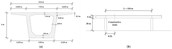
Figure 1.
Assumed post-tensioned bridge deck design: (a) section; (b) elevation.
3.2. Model Preparation
3.2.1. Parametric Design
In this project, a numerical OMSS simulation is proposed as a case, and it was designed for cast-in-place box girder bridge deck construction. The maximum span of the bridge was required to be 110 m. For such a long-span bridge deck construction, special designs should be considered, and several precedents are referenced. In recent years, the construction ability of the OMSS has reached 90 m. MSS M1-90-S, an OMSS model designed by BERD, has successfully been applied in a cast-in-place high-speed rail (HSR) post-tensioned box girder bridge deck construction project in Turkey [4]. The OMSS model took advantage of the natural geometry of a steel trussed arch and the innovative Organic Prestressing System (OPS). The OPS can actively control mid-span deflections; however, this system was not considered and simulated in this project. Other design philosophies, such as the arch embedded in M1-90-S, were also borrowed to develop the new OMSS prototype for 110-metre-span bridge superstructure construction.
To effectively obtain the most appropriate model, the parametric design method was applied using Rhinoceros 3D Version 8 (Rhino 8) with Grasshopper, a powerful three-dimensional CAD modelling software with parametric design features. Preliminary structural optimisation was conducted through Karamba3D, a finite element analysis (FEA) tool within Grasshopper. Subsequently, a line structure model was produced and imported into Strand7 for detailed numerical analysis.
Like the typical modelling process using other software, a clear modelling logic should be derived in advance, as shown in Figure 2. The whole OMSS model can be divided into six components: (1) primary girder (main girder); (2) secondary girder (sub-girder); (3) primary arch (main arch); (4) secondary arch (sub-arch); (5) wing; and (6) substructure. The main girder, sub-girder, main arch, and sub-arch are composed as the primary load-bearing structure, and each component can be further divided into truss and transverse bracing members. The substructure can be divided into hanger and platform.
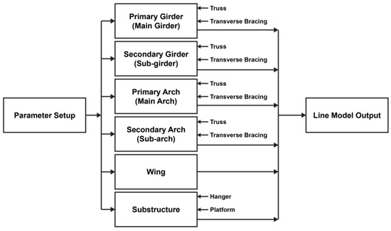
Figure 2.
Modelling logic for parametric design in Rhino 8 Grasshopper.
3.2.2. Detailed Modelling Process Using Rhino 8 Grasshopper
The overall modelling sequence is shown in Figure 3. The entire model was designed for development based on the main girder, as the process of developing the parametric model can be compared to the growth of a “tree” with numerous “branches”. The tree trunk needs to “root” in some fundamental parameters and model components, and those branches can spread from it. In changing the basic parameters and components, the whole model will be changed correspondingly. Other parameters may also be required to trim the branches and maintain them in the “shapes” required.
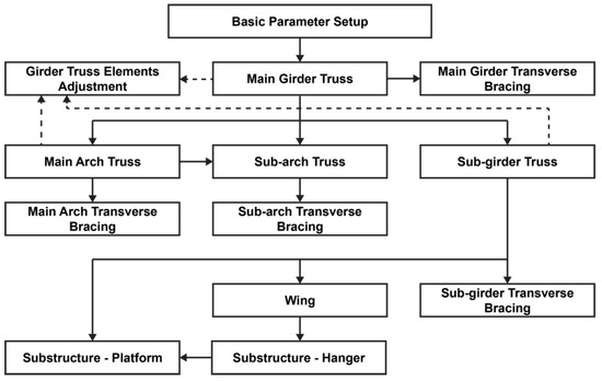
Figure 3.
Modelling sequence.
The first component to be modelled is the main girder on which the other parts can be built. The sub-girder is modelled second, followed by the main arch and sub-arch. As the main arch chord acts as one of the primary load-bearing elements, it should be connected to the support directly. Thus, adjustments are required on the main girder and sub-girder to allow a separated design for the members near the supports, which are considered to be subject to more axial forces and bending moments. Then, the remaining components can be modelled in the sequence of wing, hanger, and platform. The transverse bracing members can be modelled after completing each component. In the end, since the equipment is symmetrical in geometry, it can be first modelled in half and the “Mirror” component is used to complete the other half. In the following paragraphs, the step-by-step modelling processes are presented in detail.
Basic Parameter Setup
The first step involves defining the fundamental parameters that govern the OMSS geometry, as shown in Figure 4. Number Slider components are used to define various dimensions of the structure, which are derived based on precedents, bridge construction requirements, and structural engineering design philosophies. These parameters form the backbone of the MSS model, allowing for a consistent and flexible framework to adjust dimensions as needed throughout the modelling process. The entire model can be changed simultaneously by adjusting those parameters, which is convenient for design iterations.
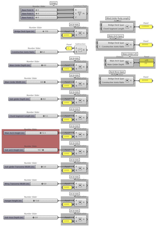
Figure 4.
Grasshopper scripts for basic parameter setup. The main arch height and sub-arch height are the main variables in this study and are colored in red.
Main Girder
The first and most critical component is the main girder, which is subject to major bending moments, contributes to the rigidity of the whole structure, and connects the upper and bottom parts. It can be further divided into the main girder truss and transverse bracing. The main girder truss consists of three parts—the body, back nose, and front nose—though they are combined together in the following analysis stages. Each of these parts was modelled parametrically with a series of Grasshopper components to meet the overall design requirements, and the detailed modelling process was packaged as a Cluster for clarity, as shown in Figure 5.
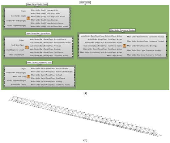
Figure 5.
Main girder: (a) subdivided components; (b) model view.
Main Girder Truss
The main girder truss was modelled through several parts, including top chords, bottom chords, verticals, and bracings, as shown in Figure 6. Modelling separate structural elements can allow for a more detailed and flexible structural analysis, as each part can be assigned different beam properties. The modelling process starts with defining the base vertical, which serves as the benchmark for the whole structure from which the “branches” will grow. For the truss chords, the end points are found using the Move component based on the desired truss length spanning from the origin. The Divide Curve component is used to determine the nodes on the chords, which are extracted for the generation of verticals and bracings. Verticals are created by arraying the base vertical linearly using Linear Array. The bottom chord nodes are dispatched to pick alternate nodes. Then, grouped with the top chord nodes, the diagonal bracings between the top and bottom chords are created, where the new node list needs to be sorted before being connected as a polyline and exploded into segmented lines. The concept of sorting a list of nodes involves deconstructing the nodes into x, y, and z coordinates and sorting the coordinates from low to high based on the desired sorting direction.
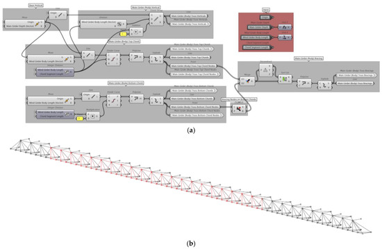
Figure 6.
Body part of main girder truss: (a) Grasshopper scripts; (b) model view. The red coloured component is the Body part of main girder truss.
As shown in Figure 7 and Figure 8, similar modelling logic can be employed in the creation of the back and front nose. Special considerations include dealing with the truss ends and finding the correct starting points to model the two components. The bottom chords are created before the top chord. As the top chord has less nodes, the Cull Index component combined with the List Length component is used to remove the nodes as needed. The correct position of the back nose is determined by the position of the constructive joint of the bridge, and the front nose truss is determined based on the length of the main arch and the overall span of the bridge deck. It is also influenced by the segment length.
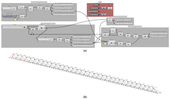
Figure 7.
Back nose part of main girder truss: (a) Grasshopper scripts; (b) model view. The red coloured component is the back nose part of main girder truss.
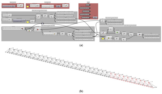
Figure 8.
Front nose part of main girder truss: (a) Grasshopper scripts; (b) model view. The red coloured component is the back nose part of main girder truss.
Main Girder Transverse Bracing
To obtain the transverse bracing elements, the top and bottom chord nodes created in previous sections are merged and sorted in two lists. Duplicate points are removed using the Cull Duplicates component. The transverse bracings can be classified depending on their produced positions, which are top chord transverse bracings, bottom chord transverse bracings, and web transverse bracings. For creating the diagonal bracings, the concept from the previous sections can be applied. Verticals can be created by moving the chord nodes based on the main girder width parameter and connecting them using the Line component. The main girder ends need special consideration while producing web transverse bracings, as they need to be created separately and merged in sequence. The Grasshopper scripts and model produced are shown in Figure 9.
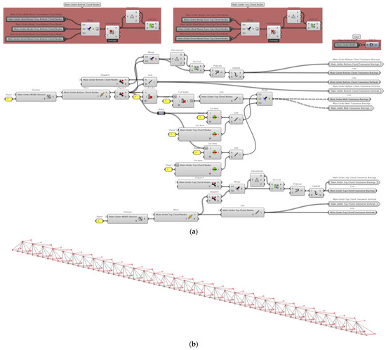
Figure 9.
Main girder transverse bracing: (a) Grasshopper scripts; (b) model view. The red coloured component is the back nose part of main girder truss.
Sub-Girder
After completing the modelling of the main girder component, the sub-girder can be created based on it. The sub-girder can be divided into two parts, the sub-girder truss and sub-girder transverse bracing. The detailed Grasshopper scripts are packaged into the clusters illustrated in Figure 10, and the model generated, coloured in red, is also shown. The parametric modelling details are shown in the following sections.
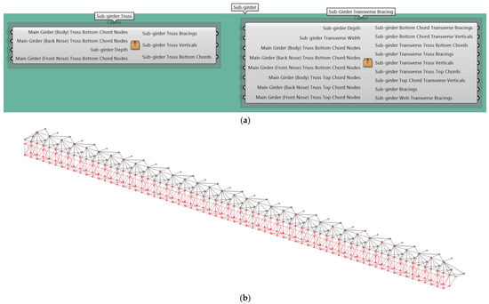
Figure 10.
Sub-girder: (a) subdivided components; (b) model view. The red coloured component is the back nose part of main girder truss.
Sub-Girder Truss
The sub-girder truss is created as depicted in Figure 11. The first step is to define the bottom chord nodes of the sub-girder truss. This is achieved by combining all the bottom chord nodes of the main girder truss and moving them to the desired sub-girder truss depth. Then, the truss web members can be generated easily using similar modelling logic described in previous sections, taking advantage of the Cull Index, Dispatch, and Sort List components. The Cull Index component can be used to remove the undesired points. Alternate nodes can be extracted using the Dispatch component to create diagonal bracings. The Sort List component ensures that the truss bracing members can be connected sequentially with the Polyline component and then exploded into segmented lines for Strand7 analysis.
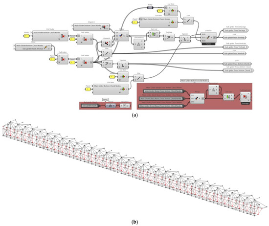
Figure 11.
Sub-girder truss: (a) Grasshopper scripts; (b) model view. The red coloured component is the back nose part of main girder truss.
Sub-Girder Transverse Bracing
The sub-girder transverse bracing component is created as shown in Figure 12. The main design logic is the same, where the positions of the chord nodes are determined by moving the existing chord nodes on the main girder truss by the input distance. Then, the remaining parts of this component can be produced.
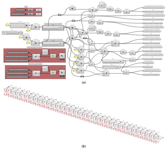
Figure 12.
Sub-girder transverse bracing: (a) Grasshopper scripts; (b) model view. The red coloured component is the back nose part of main girder truss.
Wing
The wing component can be generated as a whole, as shown in Figure 13. The major modelling logic embedded remains similar to that of the previous sections. The challenging part is determining the nodes on the wing truss chords, as the truss is triangular in shape. The bottom chord is the first structural member that is modelled, and the nodes on the top chord can be obtained with the Project Point component. The top end of the hanger truss and wing web bracing can be developed depending on those nodes. The top chord is created by connecting the selected nodes on the sub-girder and the end points of the wing truss bottom chord.
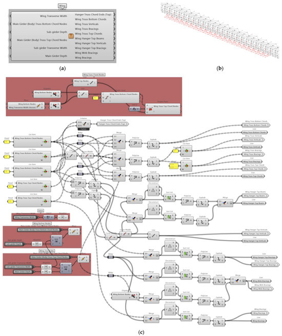
Figure 13.
Wing: (a) cluster package; (b) model view; (c) Grasshopper scripts. The red coloured component is the back nose part of main girder truss.
Substructure
As illustrated in Figure 14, the substructure component can be divided into two parts, hanger and platform. The platform is where the bridge deck formwork systems are placed and withstands the direct loads caused from concrete casting and construction activities. The platform is connected to the main girder and sub-girder parts through the hanger truss and wing on one side and the suspension bars on the other side.
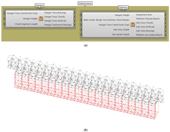
Figure 14.
Substructure: (a) subdivided components; (b) model view. The red coloured component is the back nose part of main girder truss.
Substructure—Hanger
As shown in Figure 15, the hanger truss chords are created first based on the desired hanger height. The truss webs are created by employing the Divide Curve and Dispatch components. In the modelling process, the Tree Branch component is used for dealing with the data lists with multiple branches. This data list format is maintained in subsequent parts to generate the corresponding platform elements.
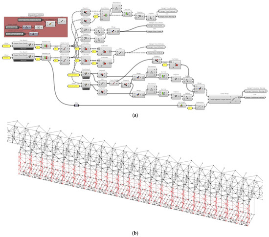
Figure 15.
Substructure hanger: (a) Grasshopper scripts; (b) model view. The red coloured component is the back nose part of main girder truss.
Substructure—Platform
As shown in Figure 16, the platform component consists of suspension bars, sub-truss, and primary and secondary beams. These structural elements are generated based on the chord end nodes of the hanger truss. The end nodes are connected and subdivided to form two rows of secondary beams. Then, the primary beams can be created by moving and connecting one row of the secondary beam nodes to the ends of the platform. It is crucial to maintain the tree data structure of the nodes. Subsequently, the sub-truss can also be created.
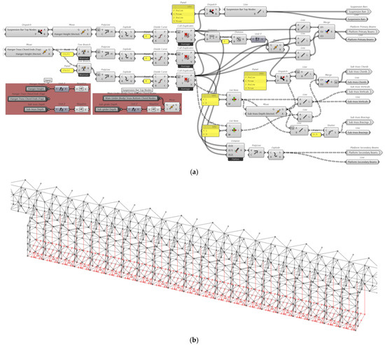
Figure 16.
Substructure platform: (a) Grasshopper scripts; (b) model view. The red coloured component is the back nose part of main girder truss.
Main Arch
The main arch component acts as one of the primary load-bearing structural members, as shown in Figure 17. It can be divided into main arch truss and main arch transverse bracing parts. Since this component needs to perform as a steel trussed arch, the two ends of the main arch truss chord should be connected to the supports through certain main girder and sub-girder truss members. Thus, the main arch chord can transfer loads to the supports.
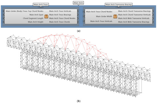
Figure 17.
Main arch: (a) subdivided components; (b) model view. The red coloured component is the back nose part of main girder truss.
Main Arch Truss
As shown in Figure 18, the base nodes needed to generate the arch are first extracted, and the midpoint of the arch chord is determined. Then, an arc curve can be created based on the start, middle, and end points before utilising the Project Point component to produce segmented arch chord members. The truss web elements are created using similar modelling logic described in the previous sections.
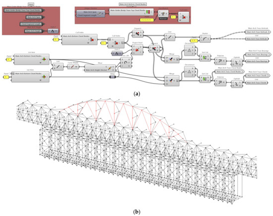
Figure 18.
Main arch truss: (a) Grasshopper scripts; (b) model view. The red coloured component is the back nose part of main girder truss.
Main Arch Transverse Bracing
As shown in Figure 19, the main arch transverse bracing members are generated. The modelling logic is the same as described in previous sections.
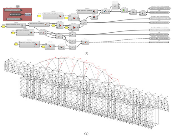
Figure 19.
Main arch transverse bracing: (a) Grasshopper scripts; (b) model view. The red coloured component is the back nose part of main girder truss.
Sub-Arch
The sub-arch component can be modelled in two parts, as shown in Figure 20: the sub-arch truss and sub-arch transverse bracing. The sub-arch helps minimise the overall deflections in the main girder and parts of the platform spanning over the bridge pier.
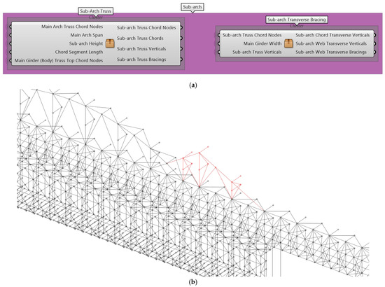
Figure 20.
Sub-arch: (a) subdivided components; (b) model view. The red coloured component is the back nose part of main girder truss.
Sub-Arch Truss
As shown in Figure 21, the generation of the sub-arch truss is similar to the modelling logic of the main arch truss.
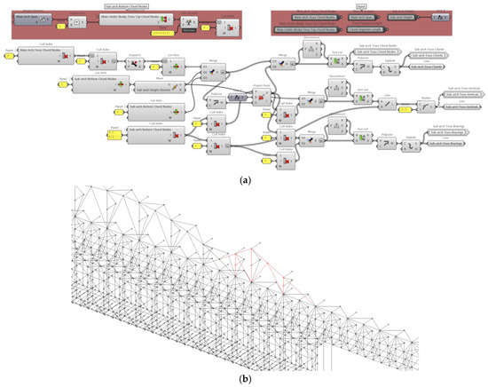
Figure 21.
Sub-arch truss: (a) Grasshopper scripts; (b) model view. The red coloured component is the back nose part of main girder truss.
Sub-Arch Transverse Bracing
As shown in Figure 22, the generation of the sub-arch transverse bracing is similar to the modelling logic of the main arch.
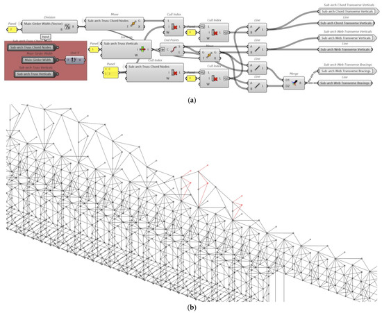
Figure 22.
Sub-arch transverse bracing: (a) Grasshopper scripts; (b) model view. The red coloured component is the back nose part of main girder truss.
Girder Truss Adjustments
As shown in Figure 23, the girder truss members near the supports are extracted and added to a separate group because those members may be subject to larger axial forces and bending moments than the other structural elements. Therefore, the extracted elements can be analysed separately and assigned larger member sections.
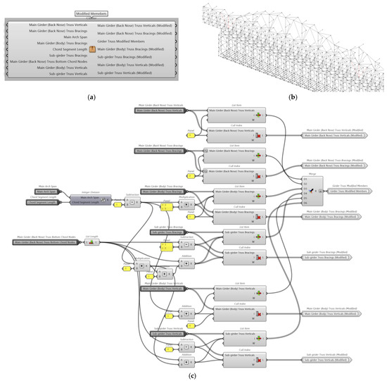
Figure 23.
Girder truss adjustments: (a) cluster package; (b) model view; (c) Grasshopper scripts. The red coloured component is the back nose part of main girder truss.
3.2.3. Detailed Structural Optimisation Process Using Rhino 8 Grasshopper
The structural optimisation in this project is more like conducting geometrical refinement. The primary load-bearing structure as a two-dimensional geometry withstands the primary loads and bending moments within the entire structural system, with the consideration of the concrete casting loading scenario. Although it is possible to conduct optimisation based on the entire three-dimensional model, limited by the available resources and confined scope of this research, the primary load-bearing frame is extracted to simplify the design process. This is achieved by employing the Karamba3D plug-in of Grasshopper. With this plug-in, the experimental mechanical property of each structural member can be assigned, and the corresponding maximum displacement can be computed through strategically applying loads at certain nodes and members. However, the results of member properties and structure analysis would not be referred to in the normal design process. They would only be employed as a “score” to rate the mechanical performance of the proposed structural geometries and arrangements. Therefore, the purpose of the optimisation in this project is to find the minimum displacement of the primary structure by changing the main arch and sub-arch heights. The “Galapagos” component is applied to find the best value of the heights with the minimum displacement under the given loading scenario. The embedded solver in this component employs evolutionary optimisation algorithms [91].
The two-dimensional primary load-bearing structure without optimisation is shown in Figure 24. The basic design concept of this structure is based on the OMSS precedent of BERD Company. The main arch is assumed to approach a perfect arch shape to obtain a better mechanical performance based on the main design concept.
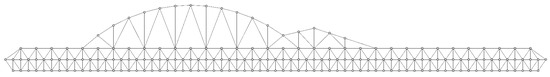
Figure 24.
Original primary load-bearing structure.
Then, its experimental maximum displacement can be calculated through a series of Karamba3D components as shown in Figure 25. “Create Linear Element” is one of the core components of this plug-in, which can assign the mechanical properties to the structural members. As the section property only affects the optimisation score, it does not influence the outcome of the optimisation process. The member names are assigned by inputting them with the same sequence as the input of those members. For those members in the main girder, the “Modify Element” component is used to treat them as pure truss elements, bearing only axial forces. The “Support” and “Loads” components are applied to define the position and value of the boundary conditions and forces. These elements refer to the structural condition of the OMSS in concrete casting phases. After that, all the edited elements are input into the “Assemble Model” component. This component can establish the finite element model for analysis. The support and applied load parameters are designed based on the project requirements and processed by this component. The positions of the supports and loads are presented in Figure 26 on the next page. These properties and the deflections obtained in later steps can be visualised using the “Model View” component. Finally, the model with finite element properties can be input into the “Analyse” component, where the value of maximum displacement can be obtained. When the main arch height is 15.4 m and the sub-arch height is 7.2 m, the displacement score is about 98.78.
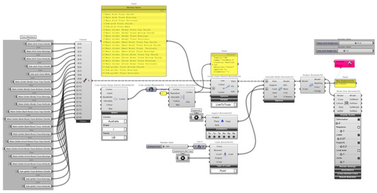
Figure 25.
Primary structure optimisation process using Karamba3D components.
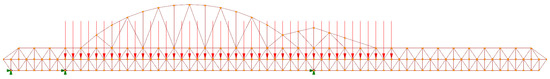
Figure 26.
Support and applied load positions on the primary structure.
The “Galapagos” component was used to find the best “form” of the structure, and its settings are shown in Figure 27. “Fitness” was set to find the minimum value of displacement for given parameters, and “population” was set to 200 to have more samples to test. If a more accurate model is expected, the values of “population” and “initial boost” can be adjusted.
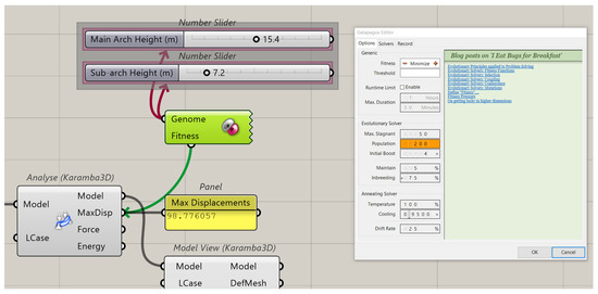
Figure 27.
“Galapagos” component editor setup.
The computation result is shown in Figure 28, and the optimised structure is shown in Figure 29. The optimised structure has a score of 73.79, which is about 25.3% lower than the score of the original. The heights of the main arch and sub-arch are 12.3 and 10.7 m, respectively. Given that the height values are limited to 1 decimal place, the solver converges at the sixth iteration, as shown in the editor window, and the best optimised score is achieved at this point.
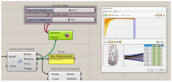
Figure 28.
Results of optimisation using Galapagos.
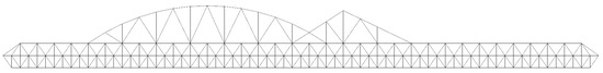
Figure 29.
Optimised primary load-bearing structure.
The results were further verified in Strand7. The numerical models had the same loading scenario and properties as the model analysed with Karamba3D. The beam property for the entire structure was considered for ideal truss members, which only need to withstand axial forces. As shown in Figure 30, the original structure has a maximum displacement score of 1.522. For the optimised structure, the score is 1.270, which is 16.6% lower, which is still a considerable decrease in the overall structural deflections. Therefore, the optimised parameters of the arch heights were applied to the model and used in the following structural analysis process.
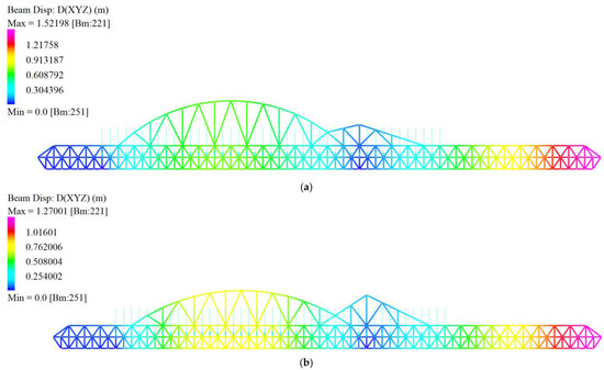
Figure 30.
Comparison of the maximum displacement of the primary structures analysed in Strand7: (a) original; (b) optimised.
3.2.4. Line Model Output for Strand7 Analysis
The optimised OMSS line model and drawings were generated, as shown in Figure 31 on the next page, which was prepared to be imported to Strand7 for the following numerical analysis. The detailed line model output setup can be referred to in following paragraphs.
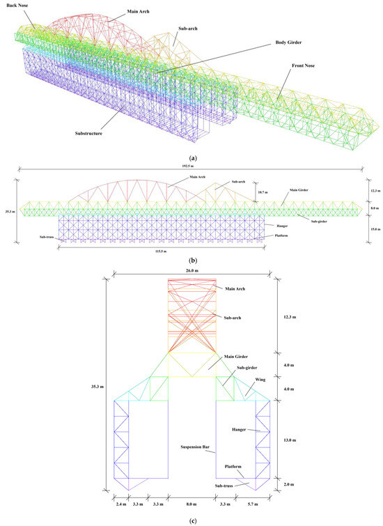
Figure 31.
Overhead MSS line model output for Strand7 analysis: (a) perspective view; (b) longitudinal elevation; (c) transverse elevation.
3.2.5. Line Model Output Setting Prepared for Strand7 Analysis
As the MSS is in a symmetrical shape, the model generated in the previous sections forms only half of the model. Thus, a mirroring process is required to complete the entire line model. The details are shown in Figure 32.
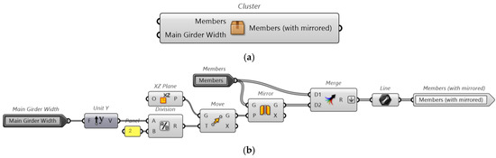
Figure 32.
Customised component for mirroring symmetrical elements: (a) cluster package; (b) Grasshopper scripts.
In taking the main girder as an example, the modelling processes for the mirroring and output settings are shown in Figure 33. To import the line model to Strand7 and set up the finite element model with beam properties and groups, various layers and colour properties need to be determined before exporting the line model using the Bake function. For a more convenient model setup in Strand7 and to identify the beam property groups, the colour code of each structural member type is assigned in hexadecimal format, which can be read directly in Strand7 software. However, the Model Layer component can only recognise colour code in RGB triplet form. Thus, a customised Script component was used, and a C# program was created to realise the desired function, as shown in Figure 34. The process for mirroring and output setup of the rest components is shown in Figure 35.
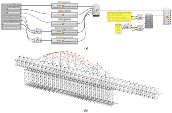
Figure 33.
Output main arch line model for Strand7 analysis: (a) Grasshopper scripts; (b) model view. The red coloured component is the main arch.
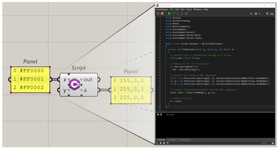
Figure 34.
C# scripts for colour code conversion from hexadecimal format to RGB triplet.
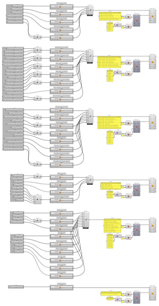
Figure 35.
Grasshopper scripts for output line models of other structural components for Strand7 analysis.
After completing the Grasshopper modelling, the line model can be baked into Rhino software, and each structural member is stored in the corresponding layer with preset layer names and colour properties. This can be observed in Figure 36. This Rhino model file can be imported into Strand7 directly.
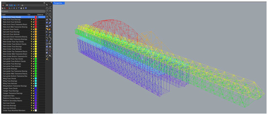
Figure 36.
Line model and layers baked from Grasshopper.
3.2.6. Line Model Import Setting in Strand7 Software
There is still not a direct connection between Rhino 8 Grasshopper and Strand7, and there is a lack of compatibility currently. Thus, the model output setting described in Section 3.2.5 is required for a more convenient model property setup in Strand7. Figure 37 shows the way to import a Rhino (.3dm) file into Strand7. “RHINO Colour as Property” and “Covert Unused Curves to Beams” should be selected. Then, the model should be refined using the “Clean Mesh” tool, as the separate line segments in Rhino lead to duplicated points at joints in Strand7.
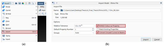
Figure 37.
Strand7 model import settings: (a) Strand7 button menu; (b) model import window.
Strand7 recognises the Rhino colour properties as beam properties and layers as groups, as displayed in Figure 38. Subsequently, the beam properties and loading scenarios can be added manually, which is explained in detail in the following sections.
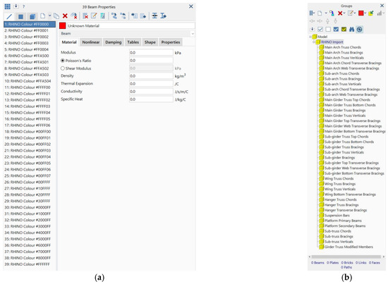
Figure 38.
Rhino file properties read by Strand7: (a) Rhino colours to Strand7 beam properties; (b) Rhino layers to Strnad7 groups.
3.3. Preliminary Design
3.3.1. Materials and Member Selection
Hot-rolled structural steel is the main material for the structural members in this project. Both hot-rolled universal beams and columns are considered. Customised welded steel sections are also applied, while available steel sections cannot satisfy the required machinal properties. In practice, the hot-rolled steel sections are required to be prepared complying with AS/NZS 3679.1:2016 [92]. Welded I sections should follow AS/NZS 3679.2:2016 [93]. However, in the framework of this study, the preset material and section properties in Strand7 are used for simplification in numerical simulation.
I sections have superior strength for bending due to their wide flanges and have excellent performance under shear force due to their webs, making them highly efficient for load-bearing structures with long-span-like bridges. High-strength bolts are assumed to be applied for member connections, and the joints are assumed to be rigid for simplified design. Steel beams are also capable of prefabrication and modular construction, which can minimise the structural imperfection and enable lower transportation costs for the equipment among different projects [94]. In addition, there have been studies confirming the feasibility of reusing steel construction materials, which is beneficial to not only control the marginal cost but also meet the sustainability requirements for heavy equipment such as the OMSS, which is mainly constructed of steel, but well-built BIM technology is required to ensure the safe operation of the OMSS over its multiple lifecycles [95]. The preliminary structural member selection and corresponding beam type setup in Strand7 were conducted before more detailed analysis, as shown in Table 3.
Table 3.
Preliminary member selection and beam type setup for each structural component.
An Excel spreadsheet was established based on AS 4100:2020 to select the proper section size with respect to the member axial force and bending moment calculated in Strand7 [7]. The details of the excel spreadsheets are shown in Figure 39, Figure 40, Figure 41, Figure 42, Figure 43 and Figure 44. There are four types of steel sections employed in this project, including universal beams (UBs), Universal Columns (UCs), Welded Beams (WBs), and Welded Columns (WCs). The specific material and section properties are based on InfraBuild’s available products [96]. Part of the welded section properties refer to a previous version of the product file prepared by OneSteel (older name of InfraBuild) [97]. Moreover, Members of IABSE Working Group 6 [32] recommended the use of high-grade steel because the strength can be increased by around 30% with a minor rise in cost (around 5%) without any influence on fatigue design, and lighter self-weight is preferred for the BCE. Thus, welded steel sections with Grade 400 and universal steel sections with Grade 350 are considered in this project. For the transverse members in each structural component, though they are designed to act as trusses, the bending capacity is still considered for those structural members, given the horizontal arrangement of those segments.
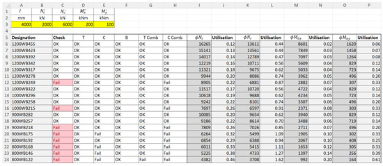
Figure 39.
Data input page of Excel spreadsheet for calculating member capacity.
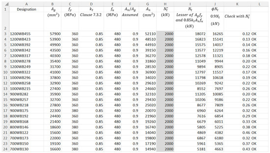
Figure 40.
Excel spreadsheet for calculating member capacity under axial tensile forces complying with AS 4100: 2020.
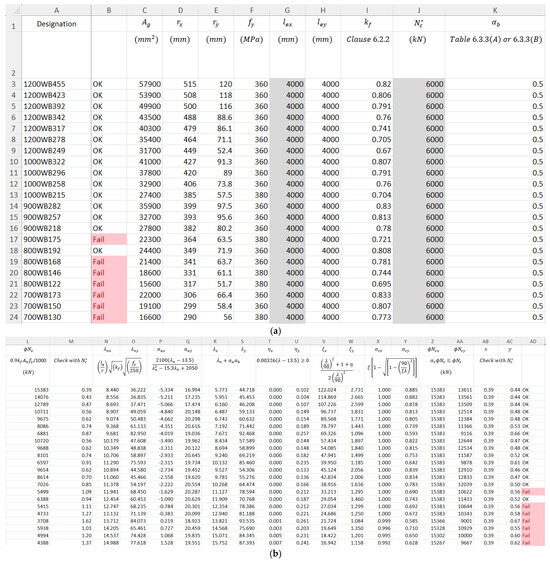
Figure 41.
Excel spreadsheet for calculating member capacity under axial compressive forces complying with AS 4100: 2020: (a) steel section properties; (b) calculation process.
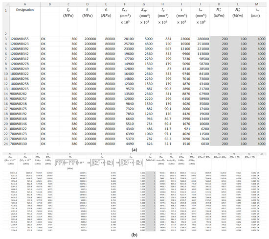
Figure 42.
Excel spreadsheet for calculating member capacity under bending moments complying with AS 4100: 2020: (a) steel section properties; (b) calculation process.
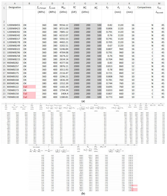
Figure 43.
Excel spreadsheet for calculating member capacity under tensile combined actions complying with AS 4100: 2020: (a) steel section properties; (b) calculation process.
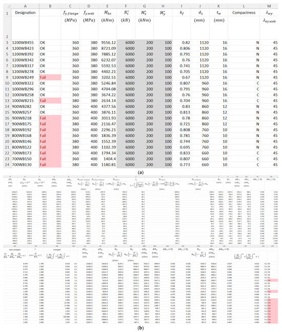
Figure 44.
Excel spreadsheet for calculating member capacity under compressive combined actions complying with AS 4100: 2020: (a) steel section properties; (b) calculation process.
Apart from the results of the member capacity calculation, which can determine the use of universal or welded sections, a general selection strategy is derived considering the special form and structural behaviour of the OMSS. For normal building structures, UBs and WBs are often used as beam members, and UCs and WCs are used as column members. Beam sections can provide greater rigidity to resist deflections and have a stronger bending capacity about the principal axis. Column sections have a remarkable buckling resistance capacity and a more balanced bending capacity in both the principal and minor axis, making them ideal for axial forces and for large bending moments in both axes. When designing the member size for an OMSS, the choice among those steel sections depends on balancing structural requirements and practicality, which relies on the results of the forces and moments on each structural member from the FEA.
The Strand7 model with the beam type and initial member size settings can be seen in Figure 45.
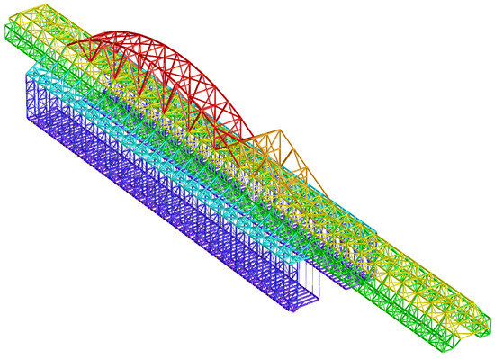
Figure 45.
Strand7 model with initial member setup.
3.3.2. Design Loads and Load Combinations
Loading Scenarios
The loading scenarios of the OMSS are determined by its operation stages divided into in-service and out-of-service stages. The in-service operation stage includes the self-launching phase and concrete casting phase. These two in-service phases form the whole working cycle and can be further divided into several operation steps. Sobotková [4] introduced the working cycle of the MSS M1-90-S model in detail, and this is referenced in this project. The operation steps include the following: (1) equipment lowering and formwork release, (2) forward movement (self-launching), (3) support repositioning, (4) equipment elevation and formwork assembly, (5) reinforcement placement, (6) first concrete casting of trough (U-shaped section of box girder), (7) formwork reposition and top deck preparation, (8) second concrete casting of top deck, (9) post-tensioning, and (10) the next working cycle. This systematic process, combining advanced automation and monitoring systems like the OPS, ensures efficient and safe construction, with each span taking approximately 14 days to complete. A detailed illustration of the operation phases can be found in Figure 46 on the last page.
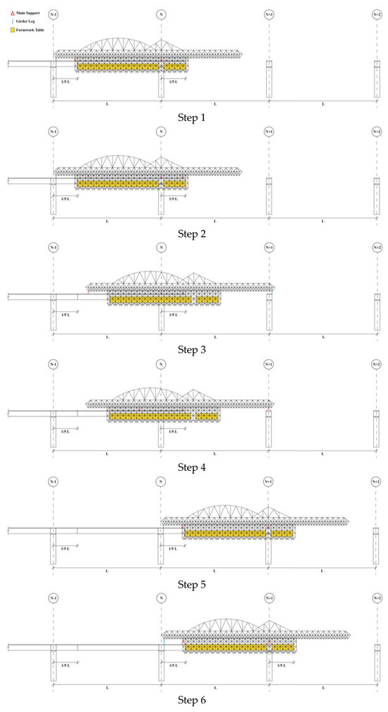
Figure 46.
Step-by-step working cycle of cast-in-place overhead movable scaffolding system.
Therefore, the whole working condition of such equipment is complicated and results in a more complex loading scenario for analysis. The mechanical capacity of the OMSS in each operation stage and working step should be carefully assessed. With regard to the limited scope of this study, only the concrete casting phase was simulated, as analysed in detail in the following paragraphs.
Permanent Actions (Dead Loads)
Dead loads include structural self-weight and superimposed loads. The structural self-weight can be calculated automatically in Strand7. The superimposed loads consist of the weight of the formwork systems, hydraulic and electrical systems, material storages, and all other accessary service facilities and materials. Rosignoli [34] declared that it is generally unnecessary to distinguish between self-weight and superimposed loads, as most loads are permanently applied and essential for operation. Those non-structural loads and any other additional load that may contribute to the permanent action can be converted to an increase of 30–40% in the structural self-weight.
However, the weight of the formwork system on the platform component is a critical parameter that needs to be considered and applied in addition to the surcharge on the structural self-weight. The resulting load can be estimated based on the typical weights used in bridge construction and general engineering judgement. As the superimposed dead loads act on both sides of the platform inner edges, the loads can be calculated in half, as shown in Table 4. The capability of the system is for heavy duty. The formwork panel material is timber, and the scaffolding material is steel. The value of the loads applied is 4.486 kN/m/side. The positions for applying the loads of the formwork system self-weight are the inner edges of the platform component.
Table 4.
Calculation of superimposed dead loads.
Typically, it is important to integrate actual mechanical components into the structural design and a more detailed analysis should be conducted, but this is not in the scope of this project [32].
Imposed Actions (Live Loads)
The concrete casting phase is analysed in this project. Thus, the weights of raw concrete and reinforcement materials contribute significantly to the live loads. To avoid overstressing the OMSS, it is important to pour the concrete starting at the cantilever tip (the far end of the equipment) and work backward toward the already cast span [32]. In this situation, the structural system is subjected to gradual loading, allowing the system to absorb bending and shear deflections properly as the concrete hardens. In addition, box girders are often cast in two phases: first the trough, followed by the deck slab, with the trough bearing some of the deck slab’s fresh concrete load [33]. The live loads on the MSS would reduce during the hardening process of the concrete and the post-tensioning. This project only considers the worse scenario, where the weights associated with the bridge deck trough (U-section) component act on the OMSS’s platform inner edges directly, which is the same case as applying the formwork system self-weight. The value of the applied loads is 152.668 kN/m. The application of live loads on the Strand7 model and the calculation process are shown in Table 5.
Table 5.
Calculation of live loads.
Wind Actions
The wind loading condition for the concrete casting phase is assessed in this project. The structural system is highly sensitive under wind loads, and its performance needs more rigorous study. As the OMSS structure can be characterised to comply with both normal steel building structural standards and crane equipment standards, a comparative study was conducted to obtain a more conservative result. AS/NZS 1170.2: 2021 provides guidance for calculating wind pressures for general building structures, and this is related to wind speed, structural height, and environmental factors [98]. According to relevant design standards of temporary structures, a 1/100 return of wind was considered [35]. Since the values of terrain and height multipliers, , are presented as a data list in AS/NZS 1170.2, Table 4.1, an interpolated function can be created by plotting the points into Excel and applying a logarithmic trendline. The function is
This allows the wind load to be applied as a function based on the structure’s height on each member in Strand7. As the assumed pier height is 30 m and the base point of the OMSS model is at (0, 0, 0), the value of the height variable, , is increased by the pier height of 30 m plus the height from the pier top to the bottom of the main girder truss, which is 13 m. As the OMSS can be considered an exposed lattice truss structure, the aerodynamic shape factor, , is determined, complying with AS/NZS 1170.2, Appendix C. The arch, girder, and substructure components of the equipment have different values of . To compute the aerodynamic shape factor of each component, the structure type is considered a single open frame, and the general structural element width is assumed to be 700 mm to obtain the effective solidity ratio, , which represents the ratio of solid area to the total area of the structure. The calculation details are shown in Table 6.
Table 6.
Calculation of wind loads complying with AS/NZS 1170.2: 2021.
In addition, AS 5222:2021 provides the wind action design for heavy lifts and cranes, which is borrowed for this study as well [99]. While AS 5222 does not provide design wind loads corresponding to specific structural heights, the entire structural members are applied with a calculated wind UDL of 0.595 kN/m. The calculation details are shown in Table 7. This value is lower than the wind load calculated based on AS1170.2. Thus, AS 5222:2021 is not the primary reference in this study.
Table 7.
Calculation of wind loads complying with AS 5222: 2021.
The bending moments caused by the formwork table cannot be ignored in this project. Referring to AS/NZS 1170.2: 2021, the calculation details are shown in Table 8. Some of the factors for calculating the design wind pressure are the same as the factors determined in Table 6. The wind pressure is converted into equivalent bending moments exerted on the inner ends of the platform’s primary beams.
Table 8.
Calculation of wind loads caused by formwork table.
Moreover, a wind analysis of the formwork system at the platform level was also conducted. Those loads are converted to equivalent bending moments on the platform edge beams. To obtain a more conservative result, wind loads are applied from three different directions: perpendicular (orthogonal), and at 45 degrees both upward and downward, as shown in Figure 47. The corresponding decomposed wind loads are included in Table 6. Dynamic wind loading analysis is ignored in this study.
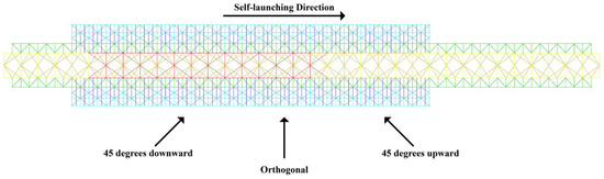
Figure 47.
Wind load directions.
Load Combinations
Although there is no universal guideline for safety factors and load combinations, as the existing national design standards are based on past experience and prevent known failures, it is crucial to ensure rigorous design compared to the existing standards [34]. The typical structural analysis method is a limit-state design, which is specifically determined in AS1170.0:2002. Since the standard is primarily intended for permanent building structures, its general principles and load assessment methodologies may not be relevant to temporary structures. However, conservative design is always required for such structures. It is crucial to reference the relevant standards that can help ensure structural safety and performance.
The load combinations defined in AS 1170 are listed in Table 9.
Table 9.
Load combinations based on ULS and SLS (AS1170.0:2002, Clause 4.2-3).
The general design principles for scaffoldings are determined in AS/NZS 1576.1:2019 [100]. These principles can be referred to in this project. The load combinations introduced in the standard are listed in Table 10.
Table 10.
Load combinations for scaffolding design (AS/NZS 1576.1:2019, Clause 2.7.2-3).
Mora Quispe, Todisco, and Corres Peiretti [28] suggested that the design load combinations for typical bridge and building structures cannot satisfy the needs of an MSS based on its application conditions. Compared to permanent structures, modern BCE has increasing complexity in its structural system and the interactions between mechanical, hydraulic, and electronic systems [34]. Thus, more conservative consideration of structural safety is required. For the static phase, the loads generated by concrete casting and strong wind are significant. Rosignoli [34] provides a recommendation for the factors of load combinations. For SLS design, dead loads and primary live loads (e.g., concrete) have a load factor of 1.0, and other loads (e.g., wind) have a load factor of 0.8. For ULS design, dead loads have factors of 1.35 and 1.38, and the live loads use 1.5. Other loads can use a lower load factor of 0.97.
In this project, permanent (dead, G), imposed (live, Q), and wind (W) loads are considered as critical. The design loads determined in previous sections are considered, and the worse loading scenario are assessed. The corresponding load combinations are listed in Table 11.
Table 11.
Determined load combinations for the structural design of MSS.
3.3.3. Linear Static Finite Element Analysis (FEA)
Linear static analysis establishes the foundational response of the OMSS under the primary load cases declared in Section 3.3.2 according to AS 1170, including permanent (dead), imposed (live), and wind loads, forming a benchmark for advanced stability evaluations [6]. The Linear Static solver in Strand7 assumes constant loads and a linear structural response [101]. This analysis calculates the initial element stress and global displacement, creating an initial stiffness matrix that represents the structure’s elastic response under the analysed operational condition, which is the concrete casting phase in this project. This approach enables the rapid and straightforward identification of critical design factors and boundary conditions, even with simplified beam models, which is sufficient for cases with less complex configurations, such as the overhead trussed box girders with arches supported by stiff bridge piers [102].
The critical axial forces and bending moments for specific members can be obtained from this analysis, which can guide member size selection and structural optimisation based on AS 4100 [7]. For the beam members, combined actions are assessed using the corresponding axial forces and bending moments for the segments that have the critical values. Moreover, the results from this linear static phase can serve as essential inputs for the subsequent buckling analyses, particularly by detailing the stiffness and stress parameters required for effective eigenvalue calculations in buckling modes.
4. Results and Discussion
4.1. Parametric Modelling
In this project, the parametric modelling of the OMSS was carried out using Rhino 8 with Grasshopper to provide a line model for numerical simulation, which is assumed to be capable of constructing a 110 m span cast-in-place box girder bridge. The overall design philosophy was borrowed from a BCE precedent, MSS M1-90-S [4]. Due to the special structural requirements of long-span bridge construction, efficient and flexible model construction was achieved through Grasshopper’s parametric design approach, allowing complex structural components to be quickly defined and adjusted. Initial structural optimisation was carried out in Karamba3D to give the model an initial mechanical adjustment to the geometry of the primary load-bearing truss, and the simplified linear model was then imported into Strand7 for in-depth finite element analysis. One of the significant advantages of this modelling approach is that the structural parameters can be adapted to different construction requirements rapidly, while ensuring a clear workflow for convenient component repositioning and design improvement.
The model is divided into six structural modules, including the main arch, secondary arch, main girder, secondary girder, wing, and substructure. The primary and secondary girders form the horizontal load-bearing framework, sitting on the foundation and connecting the upper and lower structures to maintain the structural integrity. The primary and secondary arches act as the main vertical supports, similarly to a trussed arch bridge, providing the overall structural stiffness and stability to withstand the structural self-weight and other vertical loads. The wing can further assist the overall load-carrying capacity by redistributing the loads transferred from the bottom of the substructure. Hanger trusses and suspension bars, parts of the substructure component, can hold up the platform and create a stable environment for bridge deck construction.
Through this modular division and parametric design method, the dimensions and positions of the components can be quickly adjusted according to the specific construction requirements, thus accurately and efficiently meeting the complex requirements of engineering practice in the design of the OMSS and enhancing the adaptability and operability of the model. Such a design strategy also allows the model to be prepared for subsequent structural optimisation and rigorous numerical analysis.
The limitations of the model in practical engineering applications are mainly in two aspects. Firstly, the parametric model does not include the OPS technology, which is capable of actively adjusting the mid-span deflection of the structure to reduce deformations during the construction process [24]. Due to the neglect of the OPS design, the current model is unable to achieve the real-time control of deflections, thus limiting the simulation accuracy of the real force and deformation state of the whole structure. This is particularly important in long-span bridge construction, where insufficient deflection control may lead to stress concentration in the mid-span structure, influencing the moment redistribution and increasing member sizes.
Secondly, although the model can be flexibly adjusted parametrically in Grasshopper and imported into Strand7 with prepared beam properties and model groups, there is still a lack of compatibility between the two software in setting up the model’s mechanical properties. In the current stage, the load cases and other mechanical settings in Strand7 need to be input manually after importing the line model. This situation can minimise the contribution of parametric design to improving work efficiency. Therefore, for the FEA of large structures such as OMSSs, frequent model adjustments and iterative calculations may further increase time consumption, making it difficult to respond quickly to design changes in practical engineering applications.
4.2. Structural Optimisation
The structural optimisation work focused on a 2D model of the primary load-bearing truss structure, designed to manage the principal loads and bending moments within the overall structural system. This model was mainly tailored to address the operational demands during the concrete casting phase. With the Karamba3D plug-in in Grasshopper, experimental mechanical properties were assigned to each structural element, and maximum displacements were calculated by strategically applying loads to specific nodes and members. This method assesses the deformation behaviour of the entire structure under specific load conditions and introduces a “scoring” system to quantify and evaluate the mechanical performance of various structural geometries. Although this scoring system is not typically used in conventional design, it serves as a valuable benchmark for optimisation, guiding adjustments in the structural design.
The primary goal of this optimisation is to identify a configuration with minimal displacement by adjusting the heights of the primary and secondary arches, thereby enhancing the stability of the load-bearing structure. Employing the Galapagos component—a genetic algorithm solver in Grasshopper—the project sought the optimal height configuration for the specific loading scenario, achieving a 25.3% reduction in displacement score compared to the initial design. Further validation in Strand 7 with the same model configuration and mechanical settings showed a 16.6% reduction in maximum displacement, confirming a significant improvement in controlling overall structural deformation. This optimisation approach allows for rapid adjustments to structural geometric parameters early in the design phase. Designers can explore the mechanical performance of different configurations and swiftly pinpoint a more suitable structural geometry, suggesting substantial potential for enhancing working efficiency through the parametric design workflow. However, the current optimisation methods face certain limitations. Since the optimisation is based solely on a 2D model, the results may not fully capture the complex 3D mechanical behaviour of the OMSS. The capability of this method in a 3D structural model needs further verification. Additionally, the optimisation results heavily depend on the quality of the parametric model. The programming process can be time-consuming and may lack efficiency, particularly when simulating the structure’s fundamental forces and deformation characteristics across various operational stages and analysing stress distribution and buckling effects.
4.3. Linear Static Finite Element Analysis Results
In linear static analyses, axial forces and bending moments of critical members are obtained based on different load cases. The maximum values in the results are considered to dominate the member sizing process. The member capacity is calculated by establishing an Excel spreadsheet. The maximum segment lengths and associated critical axial forces and bending moments for each structural component are applied as length, design load, and moment parameters. Thus, the appropriate member size can be selected accordingly by referring to the capacity calculation results. Combined bending and axial actions are also assessed for beam members. For a simplification of design in this project, the member sizes for members in each structural component are the same. Although this will compromise on a lower structural efficiency, a more conservative result can be obtained following the general design principle of BCE.
A summary of the analysis results, including the axial forces and bending moments for each structural member under ULS load combinations, is presented in Table 12, Table 13, Table 14, Table 15, Table 16, Table 17, Table 18, Table 19, Table 20, Table 21, Table 22, Table 23, Table 24, Table 25, Table 26 and Table 27. In those tables, bending moments are taken in absolute value. Compressive and tensile forces are negative and positive, respectively.
Table 12.
Analysis results of axial forces and member selection for primary arch (main arch) component (kN).
Table 13.
Analysis results of bending moments and member selection for primary arch (main arch) component (kNm).
Table 14.
Analysis results of axial forces and member selection for secondary arch (sub-arch) component (kN).
Table 15.
Analysis results of bending moments and member selection for secondary arch (sub-arch) component (kNm).
Table 16.
Analysis results of axial forces and member selection for primary girder (main girder) truss component (kN).
Table 17.
Analysis results of axial forces and member selection for primary girder (main girder) transverse bracing component (kN).
Table 18.
Analysis results of bending moments and member selection for primary girder (main girder) transverse bracing component (kNm).
Table 19.
Analysis results of axial forces and member selection for secondary girder (sub-girder) truss component (kN).
Table 20.
Analysis results of axial forces and member selection for secondary girder (sub-girder) transverse bracing component (kN).
Table 21.
Analysis results of axial forces and member selection for wing component (kN).
Table 22.
Analysis results of bending moments and member selection for wing component (kNm).
Table 23.
Analysis results of axial forces and member selection for substructure hanger component (kN).
Table 24.
Analysis results of axial forces and member selection for substructure platform component (kN).
Table 25.
Analysis results of bending moments and member selection for substructure platform component (kNm).
Table 26.
Analysis results of axial forces and member selection for substructure sub-truss component (kN).
Table 27.
Analysis results of axial forces and member selection for girder truss modified member component (kN).
For the truss members, 1.2G + 1.5Q dominates the axial force design, and the wind case dominates the flexural design; however, for the beam members in transverse bracing components, although the 1.2G + 1.5Q load case is still significant, the effect of the wind load case dominates the member design of some components. This is reasonable as the truss members are primarily vertical to the ground surface and support the whole structure, subjected to the gravity and imposed loads, while the transverse beam members are in the horizontal direction and withstand wind loads from various directions.
Figure 48 and Figure 49 illustrate the structural deformations under the SLS load combinations. The global deformations are assessed in the three-directional wind loads separately. The overall deformation results are in accordance with the design requirements. Mora Quispe, Todisco, and Corres Peiretti [28] suggested that the deflection limit for an MSS design for construction should not exceed L/400, where L is the length of the bridge span. In AS 5100.2: 2017, the value of deflection should be less than L/600 [89].
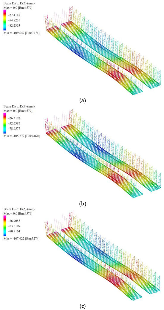
Figure 48.
Deflections of the substructure platform component under three SLS load cases: (a) orthogonal; (b) 45 degrees upward; (c) 45 degrees downward.
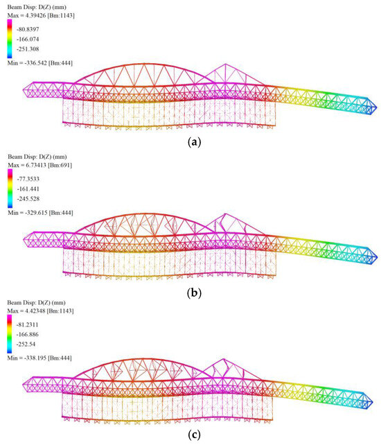
Figure 49.
Deflections of the OMSS under three SLS load cases: (a) orthogonal; (b) 45 degrees upward; (c) 45 degrees downward.
Figure 48 on the next page shows that the maximum deflection of the platform component of the equipment under the three SLS load cases with wind loads in the orthogonal, 45-degree upward, and 45-degree downward directions are 109.6 mm, 105.3 mm, and 107.6 mm, respectively. For a full-length 110 m bridge deck, these deformations are all less than L/750, meeting the recommended requirement of L/400. Controlling the deformation of the construction platform is crucial in the BCE design, as it directly affects the construction quality of the bridge superstructure. With the application of an Organic Prestressing System (OPS), the mid-span deflection of the MSS’s main girder can remain under L/1000 and further minimises the deflections on the construction platform [24].
Figure 49 illustrates the deformation of the entire structure under the three SLS load cases. The maximum deflections in the three cases are 336.5 mm, 329.6 mm, and 338.2 mm, respectively. Given the 110 m construction span of the OMSS in this project, these deformations are all below the L/350 limit. The largest deformation occurs at the furthest point of the front nose, which can be considered a cantilever beam. According to AS 4100:2020, the deflection limit for a cantilever beam is L/250 [7]. Therefore, the overall structural deformation meets the standard requirements.
Linear static analyses provide a preliminary assessment of axial forces and bending moments in structural members by assuming minimum deformations and ignoring geometric nonlinear effects. The advantage of this analysis is that it is efficient and suitable for more rigid structures with small lateral displacements, such as simple members in the OMSS. However, in complex structures, the limitations of linear static analysis gradually become apparent, especially when there is a risk of deformation and instability, which does not accurately capture the true behaviour of the structure. Linear static analysis does not consider second-order effects, such as P-delta effects [102]. This limitation makes further linear buckling analysis and nonlinear buckling analysis necessary. Linear buckling analysis determines critical buckling loads and modes by solving eigenvalue problems, which provide fundamental data for identifying potential points of instability. However, nonlinear buckling analysis is important under high accuracy demands, especially with high axial forces. This analysis combines geometrical and material nonlinearities by iteratively updating the stiffness matrix to reflect the deformed geometry, thereby analysing the load–deflection relationship and stiffness changes in detail to ensure the stability and resistance to the instability of the OMSS under loading. The combination of these buckling analysis methods will provide a more accurate basis for the comprehensive stability assessment of OMSSs, which is essential for the safety of the structure, especially in complex bridge construction equipment. Thus, these factors form the limitations of the FEA aspect of this project, and linear and nonlinear buckling analyses must be conducted in the subsequent analysis.
4.4. New Design Procedure
The previous sections provide an example of the OMSS design workflow, which can be a foundation for developing an innovative design procedure for bridge construction equipment. Although André, Beale, and Baptista [30], Rosignoli [31], Members of IABSE Working Group 6 [32], and Mora Quispe, Todisco, and Corres Peiretti [28] have developed design recommendations for the design of bridge erection and construction equipment, those guidelines are in a generalised stage based on European and American design codes, and useful information is scattered in numerous documents. A more straightforward and detailed design procedure within the environment of the Australian construction industry and the power of parametric design has been pointed out in this project, while the relevant precedents are also referenced.
This design process comprises several critical stages, beginning with a comprehensive understanding of design briefs, including analysing bridge superstructure drawings to determine appropriate construction methods and gathering information on operational and environmental conditions during construction. Thus, with further site investigation and condition monitoring, accurate design assumptions can be proposed, and a more comprehensive solution can be achieved. The overall design is based on specific standards, such as loading action determination in AS 1170 and bridge design requirements in AS 5100, and incorporates engineering expertise to confirm construction methods and sequencing. These standards and practical experience can also guide the overall structural layout and material selection for the bridge construction equipment. To emphasise the proposed new design procedure, some steps were simplified in this study, including employing assumed bridge cross-sections, working conditions, and OMSS design concepts from prior cases. The parametric modelling of the structure was then performed using Grasshopper, optimising the geometry with its built-in Galapagos component and FEA plug-in, Karamba3D.
The next stage involved detailed structural design. Various loads needed to be calculated for the FEA in the following steps. The loads included the weight of the bridge deck, the formwork system, specific wind loads, and the weight of workers and equipment. With the determination of design loads, comprehensive analysis was conducted to find appropriate load cases. Then, structural analysis and capacity calculations were required to assess the strength and stability of the proposed structural components under different loading scenarios. The analysis was carried out using the Strand7 FEA software, and the member capacity calculation was conducted using an established Excel spreadsheet based on the main design principles in AS 4100. After the completion of those design stages, from parametric modelling to numerical analysis, several iterations were required to refine the design. Finally, the structural design was finalised, construction drawings were produced, and a calculation report was prepared before advancing to the next design phase.
Due to the scope limitations of this study, only an initial design process for the temporary bridge construction equipment was proposed and validated. Given the complexity of the equipment’s overall structure, more advanced and detailed structural analyses, such as dynamic wind, thermal, and fatigue analyses, are needed to ensure structural integrity and operation safety. Additionally, functional facilities can increase the complexity of its design, which include electrical systems, hydraulic systems, and active control systems like OPSs. This requires multidisciplinary collaboration among various specialists. Therefore, an initial working procedure framework for bridge construction equipment design with the consideration of Australian conditions is proposed, as illustrated in Figure 50. The areas explored in this study are coloured in black. While some related aspects have not been validated in this project, they have been included in the flowchart in red and are suggested for facilitating future research and practical applications.
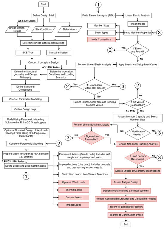
Figure 50.
Proposed new design procedure of bridge construction equipment. Where the red block shows the possible future research.
5. Conclusions and Future Research Recommendations
In conclusion, this research introduces a straightforward and practical methodology for the structural design of large-span bridge construction equipment tailored for Australian conditions, using the Overhead Movable Scaffolding System (OMSS) as a case study to demonstrate the effectiveness of the design program. The design methodology encompasses the estimation of design loads, a combination of loads, parametric modelling, structural optimisation, finite element analysis, and an iterative process for selecting structural members, all aimed at ensuring the structure’s safety, integrity, and adaptability. Using Grasshopper for parametric modelling, Karamba3D for preliminary geometric optimisation, and Strand7 for finite element linear elastic analysis facilitated a thorough assessment of the equipment’s performance under complex load scenarios. The findings from the linear elastic analysis verify that the equipment complies with the ultimate limit state (ULS) and serviceability limit state (SLS) design criteria, paying special attention to the variable impacts of wind directions on structural performance. This study lays robust groundwork for a universal design guideline applicable to bridge construction equipment, encompassing temporary and permanent structural features. Nonetheless, further exploration is essential to refine this design methodology, enhance its adaptability to various conditions, and confirm its practicality as a benchmark for Australian engineers in designing dependable and flexible bridge construction equipment.
Above all, the current research identifies several technical limitations that are recommended for further investigation:
- 1.
- Potential future research directions are outlined as follows: Explore strategies for support placement during the OMSS’s launching phase.
- 2.
- Evaluate the impacts of vibrations from the concrete casting and self-launching of structures and validate the design across different operational stages.
- 3.
- Perform dynamic wind load analysis using Computational Fluid Dynamics (CFD) and wind tunnel tests due to the high sensitivity of the OMSS to wind forces.
- 4.
- Refine parametric modelling to enhance precision in geometry and connection definitions.
- 5.
- Incorporate the Organic Prestressing System (OPS) to gain insights into overall structural behaviours.
- 6.
- Apply 3D structural optimisation to achieve the most efficient model.
- 7.
- Improve the integration between Rhino 8 Grasshopper and Strand7 and streamline the member selection process within Grasshopper to boost efficiency.
- 8.
- Undertake both linear and nonlinear buckling analyses to better understand the realistic behaviour of the structure and assess its overall stability.
- 9.
- Investigate exceptional loads, such as impact forces, seismic events, and severe wind conditions, to improve stability under extreme scenarios.
- 10.
- Conduct thermal analysis due to the temperature sensitivity of steel structures.
- 11.
- Account for geometric imperfections and human errors to enhance stability and reduce the impact of manufacturing and installation discrepancies.
- 12.
- Optimise the design of the casting cell and examine its interaction with the bridge deck.
- 13.
- Conduct sensitivity analysis to identify the factors with the greatest impact on structural integrity.
- 14.
- Compare the use of Karamba3D for structural optimisation under different circumstances.
Author Contributions
Conceptualisation, S.J. and F.T.; methodology, S.J. and F.T.; software, S.J. and F.T.; validation, S.J. and F.T.; formal analysis, S.J. and F.T.; investigation, S.J. and F.T.; resources, S.J. and F.T.; data curation, S.J. and F.T.; writing—original draft preparation, S.J.; writing—review and editing, S.J. and F.T.; visualisation, S.J. and F.T.; supervision, F.T.; project administration, F.T.; funding acquisition, F.T. All authors have read and agreed to the published version of the manuscript.
Funding
This research received no external funding.
Institutional Review Board Statement
Not applicable.
Informed Consent Statement
Not applicable.
Data Availability Statement
The original contributions presented in the study are included in the article, further inquiries can be directed to the corresponding author.
Acknowledgments
This article is an adaptation of Shaoxiong Jiang’s Honours thesis, completed at the University of Sydney under the supervision of Faham Tahmasebinia. We gratefully acknowledge Pedro Pacheco and António Morgado André for granting us access to the valuable thesis which we have also cited in our references.
Conflicts of Interest
The authors declare no conflicts of interest.
References
- Department of Infrastructure and Transport. High Speed Rail Study: Phase 2 Report; AECOM: Canberra, Australia, 2013. [Google Scholar]
- Coelho, H.; Torres, A.; Pacheco, P.; Moreira, C.; Silva, R.; Soares, J.M.; Pinto, D. Fatigue design and prevention in movable scaffolding systems. Civ. Environ. Eng. Rep. 2017, 25, 77–88. [Google Scholar] [CrossRef][Green Version]
- Prakhya, G.K.V. Temporary works in construction of bridges near third party assets. In Structural Integrity and Failure; Chapter 6; Resat, O., Faham, T., Eds.; IntechOpen: Rijeka, Croatia, 2021. [Google Scholar]
- Sobotková, M. Bowstring movable scaffolding system with organic prestressing system (OPS). e-Mosty 2017, 3, 22–36. [Google Scholar]
- AS 5100.1: 2017; Bridge design. Part 1: Scope and General Principles. Standards Australia: Sydney, Australia, 2017.
- AS/NZS 1170.0: 2002; Standards New Zealand. Structural Design Actions. Part 0: General Principles. Standards Australia: Sydney, Australia, 2002.
- AS 4100:2020; Steel Structures. Standards Australia: Sydney, Australia, 2020.
- Póvoas, A. The evolution of movable scaffolding systems and their application in the construction of the Spanish high-speed train line. e-mosty 2017, 3, 6–21. [Google Scholar]
- André, A. Estudo Experimental da Aplicação de Pré-Esforço Orgânico Num Cimbre Autolançável em Modelo Reduzido. Master’s Thesis, University of Porto, Porto, Portugal, 2004. [Google Scholar]
- Däbritz, M. Movable scaffolding systems. Struct. Eng. Int. 2011, 21, 413–418. [Google Scholar] [CrossRef]
- Pacheco, P. Pré-Esforço Orgânico: Um Exemplo de Sistema Efector. Ph.D Thesis, University of Porto, Porto, Portugal, 1999. [Google Scholar]
- Pacheco, P. Organic prestressing: An example of an effector system. Struct. Concr. 2002, 3, 107–113. [Google Scholar]
- Pacheco, P.; Adão da Fonseca, A. Organic prestressing. J. Struct. Eng. 2002, 128, 400–405. [Google Scholar] [CrossRef]
- Gümüş, M.S.; Kalyoncu, M. Fatigue failure of high strength steels under extreme vibrations of military standards: A comparative study. J. Mech. Sci. Technol. 2024, 38, 1059–1068. [Google Scholar] [CrossRef]
- André, A.; Pacheco, P.; Adão da Fonseca, A. Experimental study of a launching gantry reduced scale model strengthened with organic prestressing. Struct. Eng. Int. 2006, 16, 49–52. [Google Scholar] [CrossRef]
- Pacheco, P.; Adao Da Fonseca, A.; André, A.; Guerra, A.; Freitas, F.; Oliveira, T.; Pinto, C.; Mendes, J. Strengthening by organic prestressing of existing launching gantries in the construction of high speed railway bridge decks. In Proceedings of the Workshop Bridges for High-Speed Railways, Porto, Portugal, 3–4 June 2004; pp. 289–299. [Google Scholar]
- Pacheco, P.; Guerra, A.; Borges, P.; Coelho, H. A scaffolding system strengthened with organic prestressing: The first of a new generation of structures. Struct. Eng. Int. 2007, 17, 314–321. [Google Scholar] [CrossRef]
- Pacheco, P.; Adao Da Fonseca, A.; Coelho, H.; Jentsch, M. A new concept of overhead movable scaffolding system for bridge construction. IABSE Symp. Rep. 2008, 94, 17–24. [Google Scholar] [CrossRef]
- Pacheco, P.; Adão da Fonseca, A.P.; Resende, A.; Campos, R. Sustainability in bridge construction processes. Clean Technol. Environ. Policy 2010, 12, 75–82. [Google Scholar] [CrossRef]
- Pacheco, P.; Coelho, H.; Borges, P.; Guerra, A. Technical challenges of large movable scaffolding systems. Struct. Eng. Int. 2011, 21, 450–455. [Google Scholar] [CrossRef]
- André, A.; Ferraz, I.; Coelho, H.; Fernandes, J.; Pacheco, P. New span range on modular bridges: The arch relevance. In Proceedings of the ARCH 2019, Porto, Portugal, 2–4 October 2020; pp. 929–937. [Google Scholar]
- Pacheco, P.; André, A.; Oliveira, T.; Borges, P. Automation robustness of scaffolding systems strengthened with organic prestressing. Autom. Constr. 2010, 19, 1–10. [Google Scholar] [CrossRef]
- Pacheco, P.; Coelho, H.; Resende, A.; Carvalho, D.; Soares, I. High productivity in bridge construction: The OPS effect. In Proceedings of the Multi-Span Large Bridges: International Conference on Multi-Span Large Bridges, Porto, Portugal, 1–3 July 2015; pp. 559–566. [Google Scholar]
- Pacheco, P.; Coelho, H.; Borges, P.; Resende, A.; Carvalho, D. New frontiers in multi-span prestressed concrete deck construction: A case study. Struct. Eng. Int. 2021, 31, 106–117. [Google Scholar] [CrossRef]
- Pacheco, P.; Borges, P.; Coelho, H.; Carvalho, D. Bridge engineering optimization opportunities through integrated solutions: Design–constructive method. In Developments in International Bridge Engineering: Selected Papers from Istanbul Bridge Conference 2018; Gülkan, P., Caner, A., Memisoglu Apaydin, N., Eds.; Springer International Publishing: Cham, Germany, 2021; pp. 93–106. [Google Scholar]
- Resende, A.; Magalhães, F.; Pacheco, P. Monitoring Wind and Vibrations at Movable Scaffolding System. In Proceedings of the International Conference on Structural Health Monitoring of Intelligent Infrastructure: Transferring Research into Practice, SHMII, Graz, Austria, 1–5 September 2025; pp. 1615–1618. [Google Scholar]
- Resende, A.; Pereira, S.; Magalhães, F.; Pacheco, P. Continuous monitoring of a large movable scaffolding under operation. Autom. Constr. 2023, 156, 105084. [Google Scholar] [CrossRef]
- Mora Quispe, M.A.; Todisco, L.; Corres Peiretti, H. Design basis of movable scaffolding systems following American and European code provisions and recommendations. Balt. J. Road Bridge Eng. 2021, 16, 151–177. [Google Scholar] [CrossRef]
- Members of IABSE Working Group 6. Bridge Deck Erection Equipment; ICE Publishing: London, UK, 2018. [Google Scholar]
- André, J.; Beale, R.; Baptista, A. Bridge Construction Equipment: An Overview of the Existing Design Guidance. Struct. Eng. Int. 2012, 22, 365–379. [Google Scholar] [CrossRef]
- Rosignoli, M. Bridge Construction Equipment; ICE Publishing: London, UK, 2013. [Google Scholar]
- Members of IABSE Working Group 6. Equipment design. In Bridge Deck Erection Equipment: A Best Practice Guide; Harridge, S., Meyer, M., Eds.; ICE Publishing: London, UK, 2018; pp. 357–372. [Google Scholar]
- Members of IABSE Working Group 6. Movable scaffolding systems. In Bridge Deck Erection Equipment: A Best Practice Guide; Harridge, S., Meyer, M., Eds.; ICE Publishing: London, UK, 2018; pp. 209–245. [Google Scholar]
- Rosignoli, M. Design loads and load combinations. In Bridge Construction Equipment; ICE Publishing: London, UK, 2013; pp. 305–341. [Google Scholar]
- Australian Building Codes Board. Temporary Structures; Australian Building Codes Board: Canberra, Australia, 2015. [Google Scholar]
- National Construction Code. NCC 2022 Volume One-Building Code of Australia Class 2 to 9 Buildings; National Construction Code: Canberra, Australia, 2022. [Google Scholar]
- NSW Parliamentary Counsel. State environmental planning policy (exempt and complying development codes) 2008. In Division 3 Temporary Uses and Structures Exempt Development Code; NSW Parliamentary Counsel: Sudney, Australia, 2024; pp. 176–191. [Google Scholar]
- Tao, Z.; Brian, U.Y.; Han, L.H.; He, S.H. Design of concrete-filled steel tubular members according to the Australian Standard AS 5100 Model and Calibration. Aust. J. Struct. Eng. 2008, 8, 197–214. [Google Scholar] [CrossRef]
- Mohammadi, J.; Heydari, A.Z. Seismic and Wind Load Considerations for Temporary Structures. Pract. Period. Struct. Des. Constr. 2008, 13, 128–134. [Google Scholar] [CrossRef]
- Wang, C.H.; Pham, L. Design wind speeds for temporary structures. Aust. J. Struct. Eng. 2011, 12, 173–177. [Google Scholar]
- Fatemi-Nayeri, H.; Ancich, E. Establishing compliance of steel mill products: A comparison between Australian steel standards and the corresponding European standards. Aust. J. Struct. Eng. 2014, 15, 123–129. [Google Scholar] [CrossRef]
- Resende, A.; Coelho, H.; Pacheco, P. Preliminary assessment of wind actions in large span MSS. In Proceedings of the Multi-Span Large Bridges: International Conference on Multi-Span Large Bridges, Porto, Portugal, 1–3 July 2015; pp. 655–662. [Google Scholar]
- Moon, S.; Choi, E.; Hong, S. Creation of robust design alternatives for temporary construction in value engineering. J. Constr. Eng. Manag. 2016, 142, 04015086. [Google Scholar] [CrossRef]
- Terán, J.R.D.d.; Haach, V.G.; Turmo, J.; Jorquera-Lucerga, J.J. Improved construction of concrete viaducts with movable scaffolding systems in Spain. J. Bridge Eng. 2016, 21, 04016050. [Google Scholar] [CrossRef]
- Beale, R.; André, J. Design Solutions and Innovations in Temporary Structures; IGI Global: Hershey, PA, USA, 2017; pp. 1–501. [Google Scholar]
- Raimundo, A. A movable scaffolding system for the Vistula River in Warsaw. e-mosty 2017, 3, 37–43. [Google Scholar]
- Okere, G.; Chris Souder, M.S. Board 49: Making the case for temporary structures as a required course and recommending an instructional design. In Proceedings of the 2018 ASEE Annual Conference & Exposiiton, Salt Lake City, UT, USA, 24–27 June 2018. [Google Scholar]
- Ratay, R. Temporary structures in construction: USA practices. Struct. Eng. Int. 2018, 14, 292–295. [Google Scholar] [CrossRef]
- Solari, G. Gust Buffeting of Slender Structures and Structural Elements: Simplified Formulas for Design Calculations and Code Provisions. J. Struct. Eng. 2018, 144, 04017185. [Google Scholar] [CrossRef]
- Mohan Sai, G.; Aravindan, A. A comparative study on newly emerging type of formwork systems with conventional type of form work systems. Mater. Today Proc. 2020, 33, 736–740. [Google Scholar] [CrossRef]
- Li, F.; Zou, L.; Song, J.; Liang, S.; Chen, Y. Investigation of the spatial coherence function of wind loads on lattice frame structures. J. Wind. Eng. Ind. Aerodyn. 2021, 215, 104675. [Google Scholar] [CrossRef]
- Intekhab, M.S.; Das, S.; Jajnery, M.A.; Akhtar, S.; Sahoo, D.; Saha, P. Analysis methods of irregular high-rise buildings subjected to seismic loads. J. Vib. Eng. Technol. 2023, 11, 1359–1382. [Google Scholar] [CrossRef]
- Demarco, F.; Bertacchini, F.; Scuro, C.; Bilotta, E.; Pantano, P. The development and application of an optimization tool in industrial design. Int. J. Interact. Des. Manuf. 2020, 14, 955–970. [Google Scholar] [CrossRef]
- Barnes, M.R. Form finding and analysis of tension structures by dynamic relaxation. Int. J. Space Struct. 1999, 14, 89–104. [Google Scholar] [CrossRef]
- Saliklis, E. Structures: A Geometric Approach: Graphical Statics and Analysis, 1st ed.; Springer Nature: Amsterdam, The Netherlands, 2019. [Google Scholar]
- Block, P.; Ochsendorf, J. Thrust network analysis: A new methodology for three-dimensional equilibrium. J. Int. Assoc. Shell Spat. Struct. 2007, 48, 167–173. [Google Scholar]
- Baker, W.F.; Beghini, L.L.; Mazurek, A.; Carrion, J.; Beghini, A. Maxwell’s reciprocal diagrams and discrete Michell frames. Struct. Multidiscip. Optim. 2013, 48, 267–277. [Google Scholar] [CrossRef]
- Akbarzadeh, M. 3D Graphical Statics Using Reciprocal Polyhedral Diagrams. Ph.D Thesis, ETH Zürich, Zürich, Switzerland, 2016. [Google Scholar]
- Hablicsek, M.; Akbarzadeh, M.; Guo, Y. Algebraic 3D graphic statics: Reciprocal constructions. Comput.-Aided Des. 2019, 108, 30–41. [Google Scholar] [CrossRef]
- Ajouz, R. Parametric design of steel structures: Fundamentals of parametric design using Grasshopper. Steel Constr. 2021, 14, 185–195. [Google Scholar] [CrossRef]
- Sharbaf, A.; Bemanian, M.; Daneshjoo, K.; Shakib, H. Masonry dome behavior under gravity loads based on the support condition by considering variable curves and thicknesses. Buildings 2021, 11, 241. [Google Scholar] [CrossRef]
- Yu, Z.; Dai, H.; Shi, Z. Structural form-finding of bending components in buildings by using parametric tools and principal stress lines. Front. Archit. Res. 2022, 11, 561–573. [Google Scholar] [CrossRef]
- Estrada Meza, M.G.; González Meza, E.; Chi Pool, D.A.; McNamara Trujillo, J.S. Design Exploration of Bamboo Shells Structures by Using Parametric Tools. Appl. Sci. 2022, 12, 7522. [Google Scholar] [CrossRef]
- Cheng, J. Optimum design of steel truss arch bridges using a hybrid genetic algorithm. J. Constr. Steel Res. 2010, 66, 1011–1017. [Google Scholar] [CrossRef]
- He, L.; Gilbert, M.; Johnson, T.; Pritchard, T. Conceptual design of AM components using layout and geometry optimization. Comput. Math. Appl. 2019, 78, 2308–2324. [Google Scholar] [CrossRef]
- Azizi, M.; Aickelin, U.; Khorshidi, H.A.; Shishehgarkhaneh, M.B. Shape and size optimization of truss structures by Chaos game optimization considering frequency constraints. J. Adv. Res. 2022, 41, 89–100. [Google Scholar] [CrossRef]
- Liu, J.; Xia, Y. A hybrid intelligent genetic algorithm for truss optimization based on deep neutral network. Swarm Evol. Comput. 2022, 73, 101120. [Google Scholar] [CrossRef]
- Parisi, F.; Ruggieri, S.; Lovreglio, R.; Fanti, M.P.; Uva, G. On the use of mechanics-informed models to structural engineering systems: Application of graph neural networks for structural analysis. Structures 2024, 59, 105712. [Google Scholar] [CrossRef]
- He, F.; Feng, R.; Cai, Q. Topology optimization of truss structures considering local buckling stability. Comput. Struct. 2024, 294, 107273. [Google Scholar] [CrossRef]
- Lu, C.; Ma, X.; Mills, J.E. Modeling of retrofitted steel transmission towers. J. Constr. Steel Res. 2015, 112, 138–154. [Google Scholar] [CrossRef]
- Game, T.; Vos, C.; Morshedi, R.; Gratton, R.; Alonso-Marroquin, F.; Tahmasebinia, F. Full dynamic model of Golden Gate Bridge. AIP Conf. Proc. 2016, 1762, 020005. [Google Scholar] [CrossRef]
- Horlyck, L.; Hayes, K.; Caetano, R.; Tahmasebinia, F.; Ansourian, P.; Alonso-Marroquin, F. Blasting response of the Eiffel Tower. AIP Conf. Proc. 2016, 1762, 020003. [Google Scholar] [CrossRef]
- Knight, D.; Whitefield, R.; Nhieu, E.; Tahmasebinia, F.; Ansourian, P.; Alonso-Marroquin, F. Transient dynamic analysis of the Bao’An Stadium. AIP Conf. Proc. 2016, 1762, 020001. [Google Scholar] [CrossRef]
- Hizam, R.M.; Manalo, A.C.; Karunasena, W.; Bai, Y. Behaviour of pultruded GFRP truss system connected using through-bolt with mechanical insert. Compos. Part B Eng. 2019, 168, 44–57. [Google Scholar] [CrossRef]
- Xie, K.; Wang, H.; Guo, X.; Zhou, J. Study on the safety of the concrete pouring process for the main truss arch structure in a long-span concrete-filled steel tube arch bridge. Mech. Adv. Mater. Struct. 2021, 28, 731–740. [Google Scholar] [CrossRef]
- Rajkumari, S.; Thakkar, K.; Goyal, H. Fragility analysis of structures subjected to seismic excitation: A state-of-the-art review. Structures 2022, 40, 303–316. [Google Scholar] [CrossRef]
- Tahmasebinia, F.; Yip, C.S.; Lok, C.F.; Sun, Y.; Wu, J.; Sepasgozar, S.M.E.; Marroquin, F.A. Dynamic behavior of the composite steel–concrete beam floor systems under free and forced vibration. Buildings 2022, 12, 320. [Google Scholar] [CrossRef]
- Tahmasebinia, F.; Chen, E.; Huang, A.; Li, J. Designing Lightweight Stadium Roofing Structures Based on Advanced Analysis Methods. Sustainability 2023, 15, 3612. [Google Scholar] [CrossRef]
- Tahmasebinia, F.; Sepasgozar, S.M.E.; Shirowzhan, S.; Niemela, M.; Tripp, A.; Nagabhyrava, S.; Mansuri, k.k.Z.; Alonso-Marroquin, F. Criteria development for sustainable construction manufacturing in Construction Industry 4.0. Constr. Innov. 2020, 20, 379–400. [Google Scholar] [CrossRef]
- Tahmasebinia, F.; Jabbari, A.A.; Skrzypkowski, K. The application of finite element simulation and 3D printing in structural design within construction Industry 4.0. Appl. Sci. 2023, 13, 3929. [Google Scholar] [CrossRef]
- Tahmasebinia, F.; Jiang, S.; Shirowzhan, S.; Mann, L.; Sepasgozar, S.M.E. Exploring the integration of architectural design and advanced structural analysis for steel–glass structures: A comparative study of different case scenarios. Buildings 2023, 13, 1369. [Google Scholar] [CrossRef]
- Tahmasebinia, F.; Wang, Y.; Wu, S.; Ho, J.; Shen, W.; Ma, H.; Sepasgozar, S.M.E.; Marroquin, F.A. Advanced structural analysis of innovative steel–glass structures with respect to the architectural design. Buildings 2021, 11, 208. [Google Scholar] [CrossRef]
- Tahmasebinia, F.; Zeng, W.; Macaraniag, B.; Skrzypkowski, K. Numerical design and analysis of advanced roof systems in architecture with environmentally friendly low-carbon materials. Appl. Sci. 2024, 14, 2041. [Google Scholar] [CrossRef]
- John, S.K.; Cascardi, A.; Verre, S.; Nadir, Y. RC-columns subjected to lateral cyclic force with different FRCM-strengthening schemes: Experimental and numerical investigation. Bull. Earthq. Eng. 2025. [Google Scholar] [CrossRef]
- Wang, C.; Song, L.H.; Yuan, Z.; Fan, J.S. State-of-the-art AI-based computational analysis in civil engineering. J. Ind. Inf. Integr. 2023, 33, 100470. [Google Scholar] [CrossRef]
- Zhu, S.-P.; Wang, L.; Luo, C.; Correia, J.A.F.O.; De Jesus, A.M.P.; Berto, F.; Wang, Q. Physics-informed machine learning and its structural integrity applications: State of the art. Philos. Trans. R. Soc. A Math. Phys. Eng. Sci. 2023, 381, 20220406. [Google Scholar] [CrossRef]
- Chen, Y.; Lu, Y.; Liu, T. Seismic Performance of Precast Steel Beam-Column Joint with Bolted Connection. Buildings 2024, 14, 2588. [Google Scholar] [CrossRef]
- Ferreira, A.; Lima, B.; Lopes, F.; Pacheco, P. Comparative study of prestressing consumptions in 7 different constructive methods for 75 m multi-span box girders. In Proceedings of the Multi-Span Large Bridges: International Conference on Multi-Span Large Bridges, Porto, Portugal, 1–3 July 2015; pp. 507–512. [Google Scholar] [CrossRef]
- AS 5100.2: 2017; Bridge Design. Part 2: Design Loads. Standards Australia: Sydney, Australia, 2017.
- AS 5100.5: 2017; Bridge Design. Part 5: Concrete. Standards Australia: Sydney, Australia, 2017.
- Rutten, D. Evolutionary Principles applied to Problem Solving. In Proceedings of the AAG10 Conference, Vienna, Austria, 18–21 September 2010. [Google Scholar]
- AS/NZS 3679.1: 2016; Standards New Zealand. Structural steel. Part 1: Hot-rolled bars and sections. Standards Australia: Sydney, Australia, 2016.
- AS/NZS 3679.2: 2016; Standards New Zealand. Structural steel. Part 2: Welded I sections. Standards Australia: Sydney, Australia, 2016.
- Lawson, R.M.; Ogden, R.; Bergin, R. Application of Modular Construction in High-Rise Buildings. J. Archit. Eng. 2012, 18, 148–154. [Google Scholar] [CrossRef]
- Kim, S.; Kim, S.-A. Framework for Designing Sustainable Structures through Steel Beam Reuse. Sustainability 2020, 12, 9494. [Google Scholar] [CrossRef]
- InfraBuild. Hot Rolled and Structual Steel Products; InfraBuild: Sydney, Australia, 2019. [Google Scholar]
- OneSteel. Hot Rolled and Structual Steel Products; OneSteel: Sydney, Australia, 2014. [Google Scholar]
- AS/NZS 1170.2: 2021; Standards New Zealand. Structural Design Actions. Part 2: Wind Actions. Standards Australia: Sydney, Australia, 2021.
- AS 5222: 2021; Cranes-Wind Load Assessment (ISO 4302:2016, MOD). Standards Australia: Sydney, Australia, 2021.
- AS/NZS 1576.1: 2019; Standards New Zealand. Scaffolding. Part 1: General Requirements. Standards Australia: Sydney, Australia, 2019.
- Strand7 Pty Limited. SOLVERS: Linear Static Settings. Available online: https://www.strand7.com/strand7r3help/index.htm#Topics/SOLVERS/SolversLSA.htm (accessed on 10 October 2024).
- Rosignoli, M. Analysis and design. In Bridge Construction Equipment; ICE Publishing: London, UK, 2013; pp. 343–375. [Google Scholar]


Disclaimer/Publisher’s Note: The statements, opinions and data contained in all publications are solely those of the individual author(s) and contributor(s) and not of MDPI and/or the editor(s). MDPI and/or the editor(s) disclaim responsibility for any injury to people or property resulting from any ideas, methods, instructions or products referred to in the content. |
© 2025 by the authors. Licensee MDPI, Basel, Switzerland. This article is an open access article distributed under the terms and conditions of the Creative Commons Attribution (CC BY) license (https://creativecommons.org/licenses/by/4.0/).