Article

Methodology of Using CAx and Digital Twin Methods in the Development of a Multifunctional Portal Centre in Its Pre-Production Phase

1
Faculty of Mechanical Engineering, University of West Bohemia in Pilsen, Univerzitni 8, 301 00 Plzen, Czech Republic
2
Research and Development Department, ŠMT a.s., Tylova 57, 316 00 Plzen, Czech Republic
*
Author to whom correspondence should be addressed.
Appl. Sci. 2025, 15(6), 3312; https://doi.org/10.3390/app15063312
Submission received: 29 January 2025 / Revised: 14 March 2025 / Accepted: 15 March 2025 / Published: 18 March 2025

Abstract

:
The latest phase of the industrial revolution (Industry 4.0 and Industry 5.0) involves a large number of key areas that are crucial to improving the performance of technical systems. Computer-aided design and computer-aided engineering are important in their development and the digital twin of systems is one of the key tools for optimising their properties. This research deals with the use of these tools in the development of a machine tool. Nowadays, these tools are usually used separately. The aim of this work was therefore to propose a widely applicable methodology that would suitably combine the previously mentioned tools and thus use their synergistic effect. The proposed methodology was used on a specific machine, namely, a multifunctional portal centre, where features of computer-aided engineering (modelling, topology optimisation, stiffness and stress analyses, modal analyses, and analytical calculations) were combined with tools using the digital twin. The advanced simulations and the creation of the digital twin were performed in the pre-production phase of the machine and are described in detail within this paper. The aforementioned methodology was used to obtain and verify the final dimensions of the developed machine centre, which were the expected results. The proposed dimensions were verified in this way in terms of the mechanical properties of the designed machine (stiffness, strength, and modal properties), in terms of the suitability for machining the specific part, and in terms of the moved masses and drive parameters.

1. Introduction

Computer-supported design is a key element concerning the areas of Industry 4.0 and Industry 5.0. The main research problem and content of this article is to find a suitable combination and sequence of CAx (computer-aided), digital twin, and other methods in form of methodology for the development of a machine tool. The proposed methodology was used to find and verify the optimal dimensions and shape of the machine with respect to its individual parts (in terms of mechanical properties, machining technology of a specific part, and mechatronic concept of the machine). All of these areas are described in detail in the following subsections. The last subsection includes a summary of related research.

1.1. Industry 4.0 and Industry 5.0

The development of the manufacturing industry is closely linked to economic and social progress and has therefore undergone considerable evolution in recent decades. Its latest phases are named Industry 4.0 and Industry 5.0 [1]. Their main characteristics include intelligent manufacturing [2], autonomous machines [3,4], safe machines [5,6], automation in manufacturing [7], computer support for all phases of the product life cycle (pre-production and production phases) [8], wireless interconnection of individual systems, Internet of Things [9], Internet of Services [10], robotics, self-decision systems, 3D printing [11], sensors, big data [12], digital twin [13], cloud computing [14], artificial intelligence [15], and others. There are several differences between Industry 4.0 and 5.0. The main difference is that Industry 4.0 is technology-driven while Industry 5.0 is value-driven and considers humans as a key part of the production system [16]. Industry 5.0 and industrial progress in general are marked by the emergence of disruptive technologies that bring significant economic and social impacts with them. The benefits of Industry 5.0 can be found where Industry 4.0 fails. This is the area of promoting a more fair and sustainable society in which there is symbiosis between man and machine (robot) [17]. Machine tools together with forming machines [18] are one of the most frequent representatives of production machines [19]. The basic function of a machine tool is to process a workpiece into the desired shape, dimension, and surface quality of functional surfaces by machining. Machine tools are complex technical systems and have seen significant growth in recent years. Just as there are several phases of industrialisation, machine tools have gone through different phases of technological development and are often called Machine Tool 1.0–4.0 [20]. In the recent era of Machine Tool 4.0, the process of convergence of a physical machine tool and its virtual prototype is described as a cyber-physical machine tool (generally called a cyber-physical system) [21,22].

1.2. Focus on Machine Tools

Machine tools can be viewed from several different perspectives. In terms of kinematics, they are divided into machines with parallel kinematics and machines with serial kinematics. Machine tools can also be divided according to the main cutting motion. This motion can be either rotary or rectilinear. The basic types of milling machines include cantilever milling machines, table (bed) milling machines, plane milling machines, portal milling machines, and special milling machines. In terms of design, there are three basic types of portal centres:
  • Fixed gantry machine (table-top design);
  • Upper gantry;
  • Bottom gantry.
The scope of the research is the utilisation of CAx (computer-aided) methods and the digital twin of a multifunctional bottom gantry centre. The main advantages of the gantry frame machine tool design include uniform stress distribution in the machine frame due to its symmetry, high productivity, a wide range of feasible technological operations, and the possibility of adding accessories to the machine tool. Specifically, these are milling and boring heads that extend the capabilities of the machine tool. This enables multi-axis machining of workpieces of various complex shapes. The multifunctionality of the machine in this case consists of the possibility of performing all operations (milling, drilling, turning, and grinding operations) on one machine and to machine complex workpieces (e.g., engine blocks), as well as rotary workpieces of lower heights and of any shape complexity. Typical examples of the workpieces for which the machine is designed include propellers, components for wind turbines, and components from the renewable energy field (rotors, turbine blades, etc.). Recently, customer demands are often associated with requirements for increasing the cutting parameters of machine tools. Further increases in machine tool parameters (in this case, power, speed, torque, feed, cutting speeds, etc.) can simply lead to unstable machine behaviour during machining or shorter life of the cutting tool. These increased cutting parameters must be included in numerical simulations during the development of a machine.

1.3. CAx and Digital Twin Methods

Developing the final machine is a time-consuming and often inefficient process. Today, machine tool manufacturers cannot afford the time and cost of manufacturing and testing physical prototypes. For these reasons, it is suitable to use virtual prototyping tools and CAx tools in general to predict weak points and optimise machine design [23,24,25]. CAx methods include computer-aided design (CAD), computer-aided engineering (CAE) [26], and computer-aided manufacturing (CAM) [27]. These tools allow to simulate the complex behaviour of a real machine in the pre-production and production phases and to design and compare individual variants of a technical system. Using these tools (numerical analysis of the virtual prototype) is suitable to verify each step of the design to ensure that the designed machine meets all requirements. This places high demands on HW and SW equipment. In particular, advanced numerical simulations (stress, static stiffness, and modal analyses to calculate eigenmodes and natural frequencies) and various types of optimisation (geometric, mass, topology [28,29], and optimisation of the wall thickness of the part) can be used in the structural design of machine tools. For the complex prediction of the behaviour of a technical system, a combination of these procedures (CAx) with the principle of using the digital twin of the machine seems to be suitable. The exact procedure is developed in the form of a methodology and is described in the following section.
The concept of a digital twin appears to be the most effective method of optimising manufacturing and logistics processes. It fits fully into the areas of Industry 4.0 and Industry 5.0, which aim to integrate digital technologies into industrial processes (manufacturing processes) and which are described in the introduction of this research. There are several types of digital twins, which differ according to the phase of the product life cycle at which the digital twin model is created. A digital twin can be created before the actual manufacturing starts or after the (real) machine has been built. In the first case, the digital twin will detect defects before the machine is manufactured or commissioned. It results in significant cost savings and a reduction in the time of the entire production process. In the second case, the behaviour of the manufactured (real) machine can be optimised or its virtual commissioning can be performed. This brings significant cost savings, because any critical conditions can be debugged on a virtual machine, not a real one. If the digital twin extends to all phases of the product life cycle, we talk about the so-called digital thread. In general, digital twins are divided into:
  • Digital twin of a product—This is a computer model of a product (for example, a real machine tool) on which its behaviour can be simulated. This means not only its stiffness but generally its functioning under certain conditions, specifically kinematic links between bodies, movements, communication (signals), or control system. Based on the data obtained from the virtual digital twin, it is possible to evaluate the behaviour and performance of the real machine.
  • Digital twin of a process—It simulates complex processes such as a manufacturing plant, power grid, etc. It allows to analyse processes in real time.
  • Digital twin of a system—It simulates entire systems, integrating several digital twins of products or processes together. For example, this includes simulations of transport networks, cities, etc.
Case studies for machining a specific part with a specific tool technology can be performed using the digital twin of a machine tool. In this way, it is possible to determine machine behaviour, determine manufacturing times (main and secondary times), and predict errors and possible collisions in the workpiece-machine tool system, thus eliminating the cost of correcting them in real operation. The manufacturing of a specific part can be optimised in relation to the productivity of the machining process. It is possible to simulate the machining or mechatronic concept of the machine with the help of a digital twin. In this case, an NC code or PLC program is created. This is fully debugged, optimised, and can be used on the real machine in the final phase. All of the mentioned procedures can be implemented in the pre-production phase when the real machine is still not produced. Subsequently, after the real machine is produced, it is possible to use the obtained data, information, and signals for its testing or virtual commissioning. A closed loop engineering system (see Figure 1) can be used with different levels of virtualisation of the individual elements, namely, software in the loop (SIL) and hardware in the loop (HIL). Their exact structures could be as follows:
  • SIL—can consist of virtual SINUMERIK ONE controller Create MyVirtual Machine (CMVM) itself or it can consist of a combination of CMVM, machine PLC behaviour simulation (SIMIT), and functional 3D machine simulation (NX MCD).
  • HIL—can consist of SIMIT and real SINUMERIK hardware (e.g., SINUMERIK ONE or SINUMERIK 840D) controller and functional 3D machine simulation (NX MCD).
Full integration of artificial intelligence and machine learning methods for fault prediction on the digital twin is envisaged for the future. The digital twin will be able to learn adaptively and react to environmental conditions.

1.4. Related Research

Ref. [26] dealt with virtual prototyping and optimisation of a heavy machine tool in its pre-production phase. Machine stiffness was chosen as the evaluation criterion with differently modelled machine anchoring methods.
In ref. [30], four stages of digital twin in product design are mentioned. These are conceptual design, detailed design, design verification, and redesign. Thus, this paper suggests that there are multiple levels of digital twins in product development.
There are several papers dealing with the methodology of integration of digital twin methods and CAx computation in the design of complex products. In [31], a method was developed to integrate structure, analytical, and information models to create an interoperability engine. This method was validated on an industrial robot.
Gusev et al. [32] dealt with optimisation calculations using digital twins in the pre-production phase of product development. Both the physical characteristics of the product and its structural parameters were optimised.
Kennet [33] provides a comprehensive perspective on digital twins and their role in the fourth industrial revolution, describing a series of applications with detailed case studies of rotating machines.
Onaji [34] explored the development of the concept of the digital twin, its advancements, and its critical role in the fourth industrial revolution. He introduced the concept of the digital twin from the perspective of academia and industry, discussing its limitations and gaps in research, trends, and technical constraints hindering implementation. Research was performed to answer the question of how the concept of digital twins can support the realisation of an integrated, flexible, and collaborative manufacturing environment, which is one of the aims envisaged by the fourth industrial revolution.
Beomsik [35] optimised the machining conditions of a commercial machine tool with a digital twin. The applied model included physical models of the control system, feed drive systems, and cutting parameters. The digital twin was evaluated based on experiments. A genetic algorithm was used to determine the machining conditions in order to minimise machining time and manufacturing cost.
Zhang et al. [36] was working on creating a digital twin using MCD and TIA Portal tools. The digital twin was used for virtual debugging. It was shown that the simulation of the virtual model was in agreement with the real product. This approach helped to achieve efficient debugging, monitoring, real-time control, and reduced labor costs.
Schacht et al. [37] used SIMIT to create a safety instrument system for the W7-X reactor. This system was designed to ensure personnel safety and investment protection. The system was subsequently successfully tested.
In ref. [38], SIMIT was used to create a prototype of a processing plant. The result was a model of the processing plant that could be used throughout its life cycle to facilitate changes and optimisation of processes within the plant.
Ref. [39] dealt with the creation of basic architecture types that can be used to connect systems such as NX MCD, SIMIT, TIA Portal, and PLCSIM. According to the results, the distributed architecture was the best in terms of project time and PLC code modification.

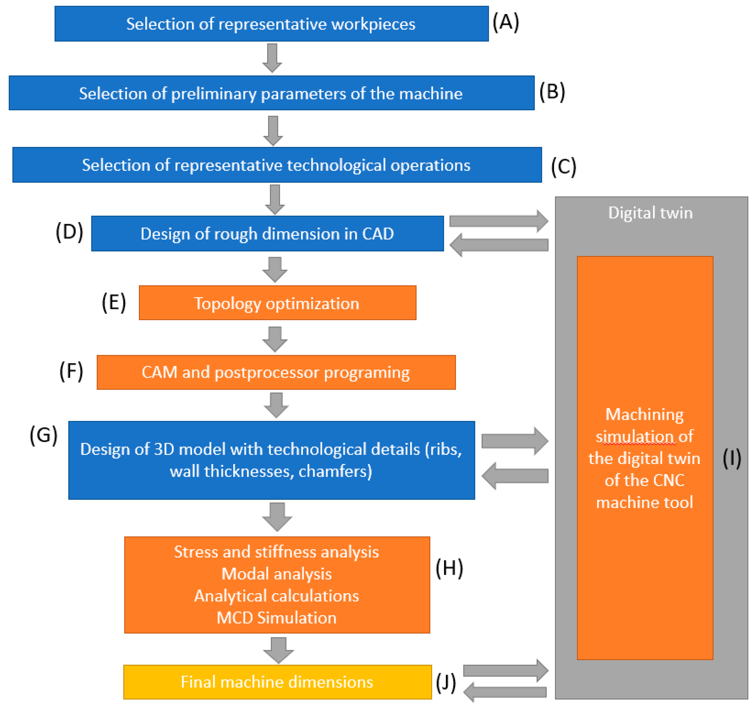
2. Methodology of Using CAx and Digital Twin Methods in the Development of a Multifunctional Portal Centre

The aim of this research was to develop a methodology for using CAx and digital twin methods. The proposed methodology should be universally and broadly applicable in machine tool design. The methodology will be verified in the development of a multifunctional portal centre in its pre-production phase (see next section). This is a universal heavy machining centre designed for metal cutting. The application of the methodology is limited only to numerically controlled machines whose control system supports the creation of a digital twin of the machine. Another limiting factor is the necessary knowledge of representative workpieces, machine parameters, and representative technological operations. It is therefore advisable to carry out a marketing study in the area of the proposed machine (competitive solutions, existing machine tools, etc.) before the design process. The proposed methodology is shown in Figure 2.
At the beginning of the research, it was necessary to select representative workpieces (A—see Figure 2), followed by the selection of preliminary parameters of the machine (B), and the selection of representative technological operations (C). The selected technological operations were characteristic of the chosen workpieces (in terms of shape) and were also crucial for the resulting concept of the machine (dimensions, lifetime, other technical parameters, and design of accessories). These technological operations were the basis of a load spectrum that was used to load the machine in computer simulations. Subsequently, the rough dimensions of the machine were designed and a 3D model was created using CAD tools (D). This model was used as input to the topology optimisation (E), including individual machine parts (especially the gantry part). This part was composed of two columns and a cross-piece of the machine. The output was an optimised model in terms of material utilisation in the structure. Furthermore, a CAM simulation (F) was performed, including the applied technological operations and to generate a postprocessor. The dimensions and shapes of the resulting model had to be modified to respect the manufacturing technology. The output was therefore a 3D model with technological details (G), namely, the ribs, wall thicknesses, technological chamfers, etc. The model was used for advanced computational simulations in the form of stress, stiffness, and modal analyses (H). A digital twin of the machine was also created at this phase. Case studies of machining simulations (I) of representative workpieces were performed on this digital twin. The results were then used to modify the 3D model (dimensions). The digital twin could also be in the future used for virtual commissioning of the machine [40]. The resulting model had to be modified according to the manufacturing technology, because it was specified that the part would be designed as a casting. Based on these calculations and taking into account the manufacturing technology of the parts, the model was optimised with respect to the static stiffness, stress and dynamic behaviour of the whole structure. The next step involved using the initial phase of MCD simulations (H) [41] to verify the dimensions of the machine in terms of its kinematics, actuators, and sensors. The integration with SIMIT software was not performed at this phase. The designed dimensions, wall thicknesses, and direction of the ribs were optimised in the individual parts using CAD tools. The initial 3D model (after minor idealisation) was then used as a basis for the creation of the digital twin of the machine [42] in the second phase of design. Case studies of machining simulations of representative workpieces were again be performed on this digital twin. The outputs were then used to modify the 3D model and the final design of the machine (J) was obtained.

3. Application of the Proposed Methodology

The proposed methodology was applied in the design of the portal centre. The individual steps of the application of the methodology are described in detail in the following subsections.

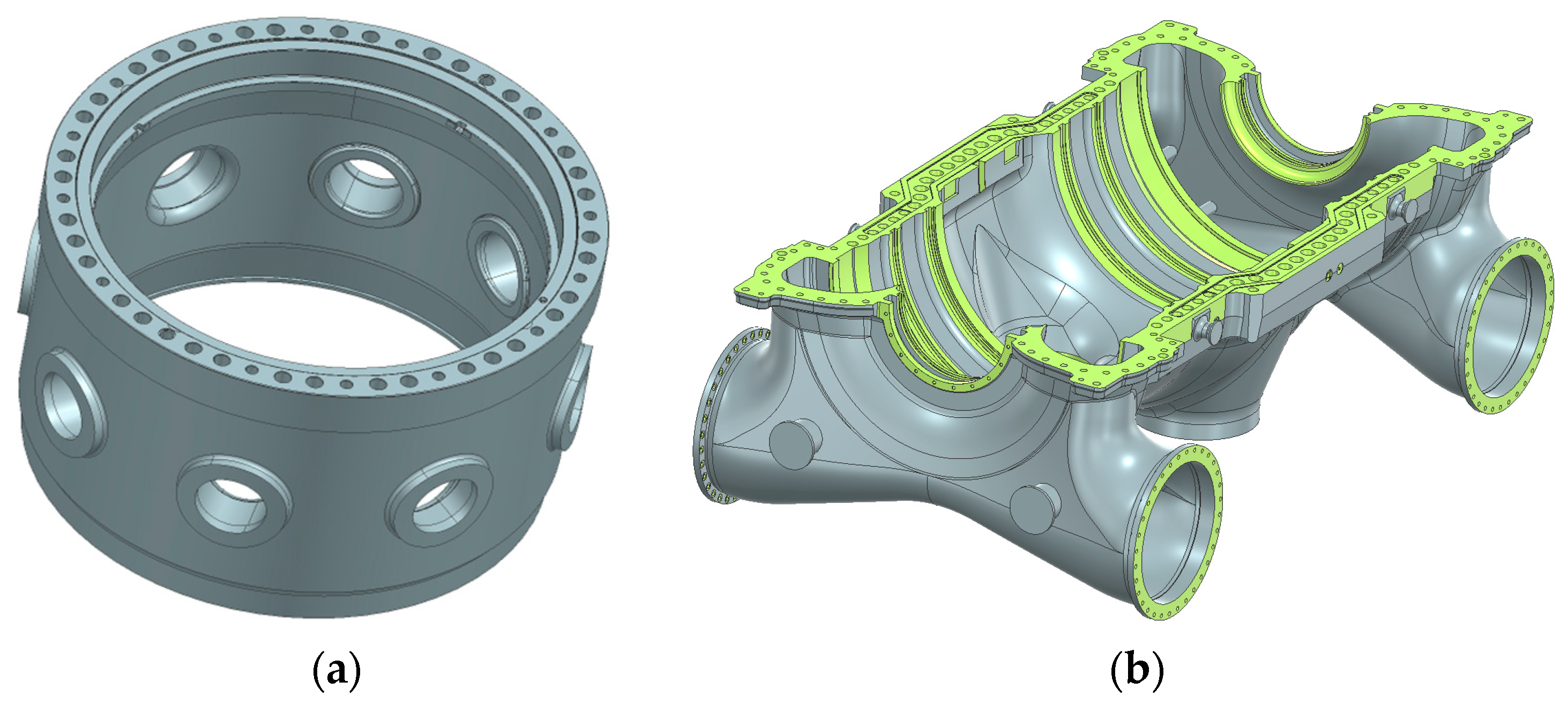
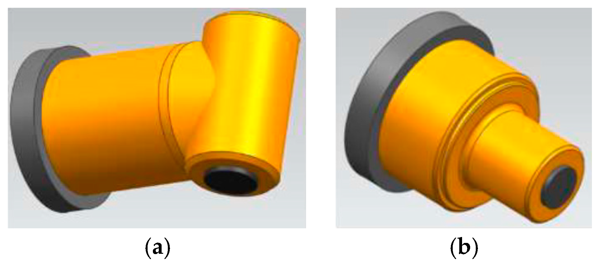
3.1. Selection of Representative Workpieces

This is the first step of the proposed methodology (see A on Figure 2). For the purposes of the simulations, it was necessary to select several representative workpieces, see Figure 3 and Figure 4.
Namely, the welded structure (a) and the propeller blade (b).
Namely, the steam generator body ring (a), and the turbine body (b). These workpieces involve characteristic technological operations that will be described in detail in the following section.

3.2. Selection of Preliminary Parameters of the Machine

This is the next step of the proposed methodology (see B on Figure 2). In order to understand the orientation of the individual axes of machine movement, it is advisable to use the nomenclature, see Figure 5.
The following is a description of the marking of the X-, Y-, Z-, and W axes. The X-axis describes the movement of the gantry on the bed. The Y-axis describes the movement of the headstock on the cross piece. The Z-axis describes the extension of the slide from the headstock and the W-axis describes the movement of the cross-piece on the column. The basic parameters of the machine were selected and are shown in Table 1.
The parameters were chosen based on selected representative workpieces, technological operations (see Section 3.1 and Section 3.3), and with respect to the parameters of existing machines of different manufacturers (Waldrich Siegen (Siegen-Germany), PAMA S.p.A. (Roverato-Italy), SCHIESS (Aschersleben-Germany), TOS KUŘIM—OS, a.s. (Kuřim-Czech Republic), FERMAT CZ s.r.o. (Prague-Czech Republic), etc.).

3.3. Selection of Representative Technological Operations

This is the next step of the proposed methodology (see C on Figure 2). Subsequently, the technological operations that are characteristic for the mentioned workpieces were selected. For each operation, a different tool and cutting conditions (cutting force, power, torque, and speed) were determined. The special CoroPlus® Tool Guide from the Sandvik Coromant (Sandviken-Sweden) tool manufacturer’s website was used for this purpose. The load spectrum, including the cutting conditions, is summarised in Table 2.
The individual load cases (or cutting parameters) were used in the subsequent numerical simulations.

3.4. Design of Rough Dimensions in CAD

This is the next step of the proposed methodology (see D on Figure 2). The rough dimensions of the multifunctional portal centre had to be defined for further simulations, see Figure 6b.
These dimensions were chosen based on the dimensions of gantry machines of selected manufacturers. The dimensions were also chosen with regard to the basic parameters of the machine and also based on the dimensions of representative workpieces. Based on these dimensions, an initial model was created to be used as input to the following advanced simulations. Primarily this involved topology optimisation and subsequent stiffness, stress, and modal analyses.

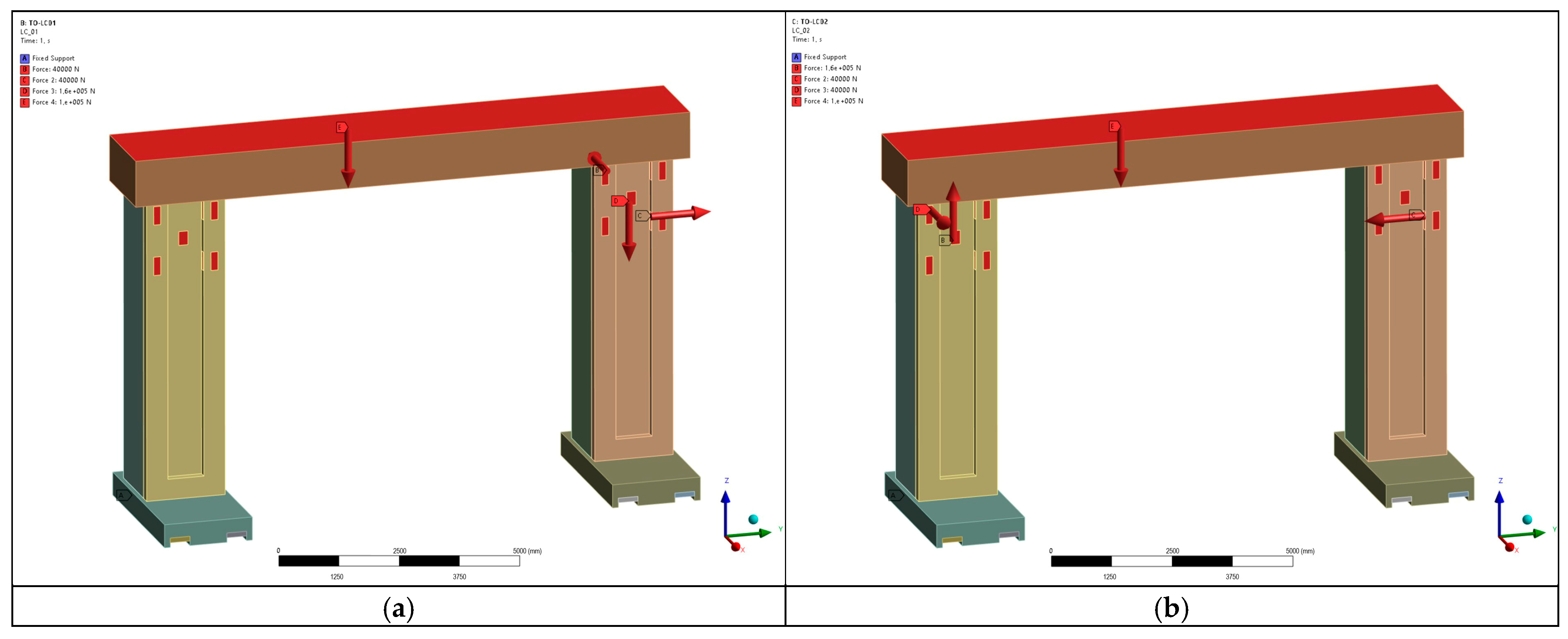
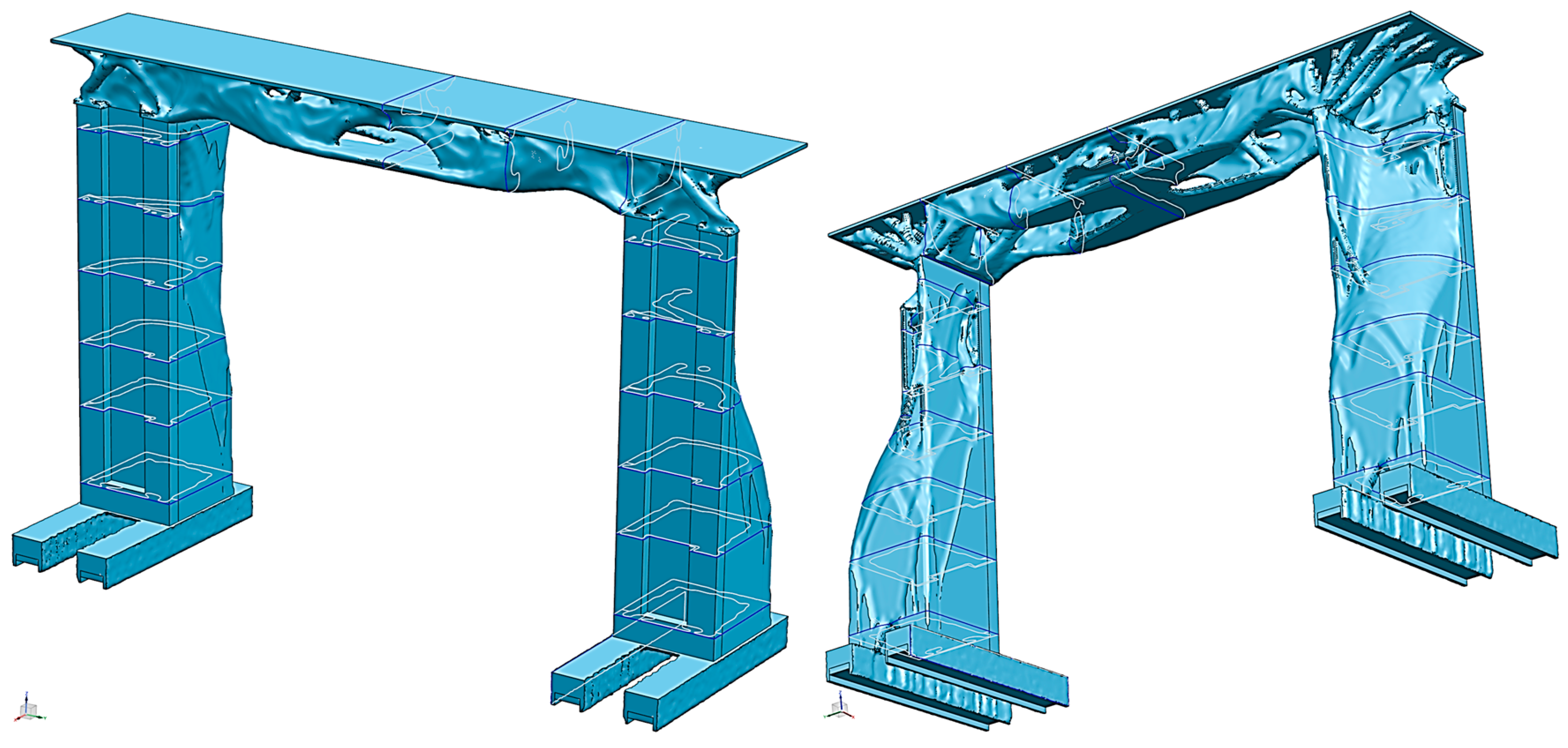
3.5. Topology Optimisation

This is the next step of the proposed methodology (see E on Figure 2). The FEM method was used for all advanced numerical simulations. It is a numerical technique [43] used for solving complex engineering problems. The behaviour of the various systems is described in this technique by the approximate solution of differential equations. The complex geometry is divided (discretised) into smaller parts (also known as finite elements). The types of elements depend on the complexity and the dimension of the problem. The set of these elements creates a mesh that is used to approximate a particular problem. The structural behaviour of each element is described by equations. By combining these equations into systems, the whole model can be described. These matrix equations are then numerically solved. The static equilibrium of the finite element model is described by Equation (1):
[Kgg]{ug} = {Pg},
where Kgg is the global stiffness matrix and includes the set of stiffness matrices of all elements. ug is the global displacement. Pg is the vector of loads acting on all scalar and grid points of the model. The ordinary structural linear simulation performs the ordering and reduction of the mentioned matrix.
Topology optimisation is one of the advanced simulation methods. It allows to design the optimal material distribution in the structure based on defined requirements. It is used to optimise the shape and structure of parts and assemblies. There are a large number of optimisation techniques that can be used for weight, reliability, stiffness, or stress-related problems. The mathematical principle is to maximise or minimise the objective function using the constraints (boundary conditions) described by Equations (2) and (3):
Find   X = x 1 x 2 x n by   minimising   f X
subject   to   constraints   { g i X 0 , h j X = 0 , i = 1 , 2 , , m j = 1 , 2 , , n
where X is the design variable, f(X) is the objective function, and the inequality and equality design constraints are denoted as gi(X) and hj(X), respectively. Size optimisation, composite optimisation, topography optimisation, or topology optimisation (TO) are all classified as structural optimisation. TO include two types of methods: the continuum approach and the discrete approach. The discrete approach of the TO is based on the selection of a discrete set of elements (presented in the structure). A large number of optimisation cycles belonging to the discrete TO group include Bidirectional Evolutionary Structural Optimisation (BESO) [44], Additive Evolutionary Structural Optimisation (AESO) [45], and Evolutionary Structural Optimisation (ESO) [46]. The material distribution in the design structure is analysed in the continuum element-based approach. The used continuum TO includes Non-Optimal Microstructures (NOM) and Dual Discrete Programming (DDP) [47], Optimal Microstructure with Penalisation (OMP) [48], Rational Approximation of Material Properties (RAMP) [49], and Solid Isotropic Microstructures with Penalisation (SIMP) [50,51]. In the proposed methodology, the input to TO was a meshed model of the portal part with rough dimensions, see Figure 7. A combination of second-order tetrahedral (type Tet10) and hexahedral (type Hex20) elements with an average size of 24 mm was used for the FEM model input (in total, the FEM model contained 6,606,236 elements).
The topology optimisation of the portal centre was performed in ANSYS Mechanical 2024 R1 with the topology optimisation module using the density-based method.
A load spectrum was applied to the model in the two independent solutions. For the load condition with the highest work torque, a cutting force of 40 kN was applied to the model in three principal directions. The cutting force was applied to the blue, green, and red surfaces and the fixed constraint was applied to the surface marked in orange (b in Figure 6). The TO was solved in two steps. In the first step, a linear static analysis of the current solution was performed to determine the minimal stiffness (or displacement) at a specific location of the machine. This displacement was then specified as a limit value in the subsequent TO. The value of the translational displacement in the x direction was set to 0.003 mm based on the calculation results. Furthermore, the objective function for minimising the compliance of the model was specified. The optimisation area was specified as the volume to be optimised with frozen constraints (conditions for keeping the material, setting the resulting pseudo-density of the material constantly at a value of 1) for the contact areas. The manufacturing constraint was set in the form of planar symmetry due to the symmetry of the model. Two input structural analyses of the simulations were specified for the force set in both positive and negative directions, see Figure 8.

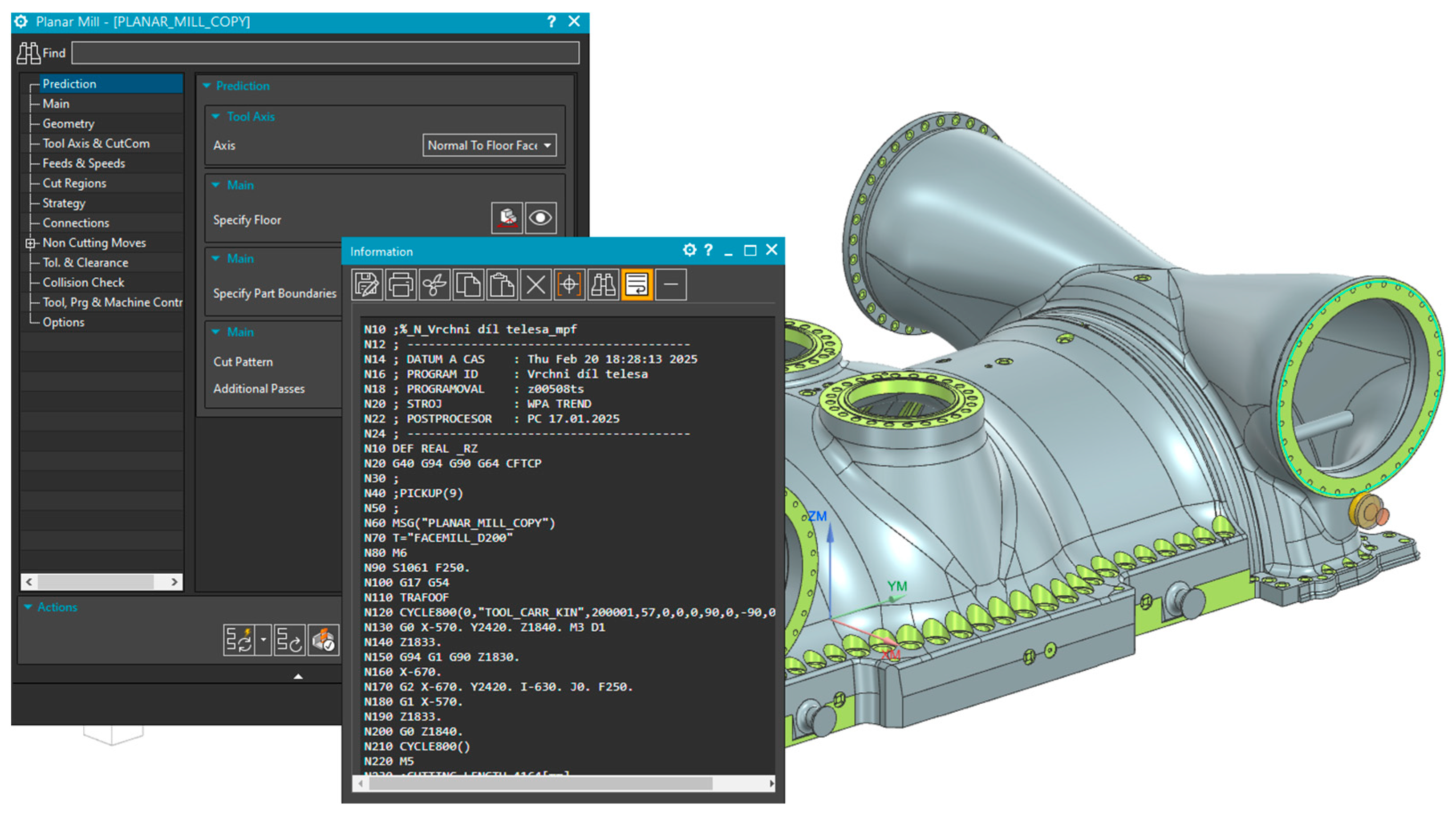
3.6. CAM and Postprocessor Programing

Computer-aided manufacturing (CAM) is computer software for programming CNC machines. It consists of various modules that are divided according to the required machining technology. Typical representatives are modules for milling, turning, drilling, wire cutting, or probe measurement. In this research, the Siemens NX CAM tool was used to design the technological operations, see Figure 9.
With the utilisation of this advanced tool, a postprocessor was developed to generate NC data for a portal milling machine. The postprocessor was designed to generate both milling and turning operations and included transformations of the kinematics according to the machine accessories. The developed NC code was then used as input for the simulations of the digital twin of the portal machine.

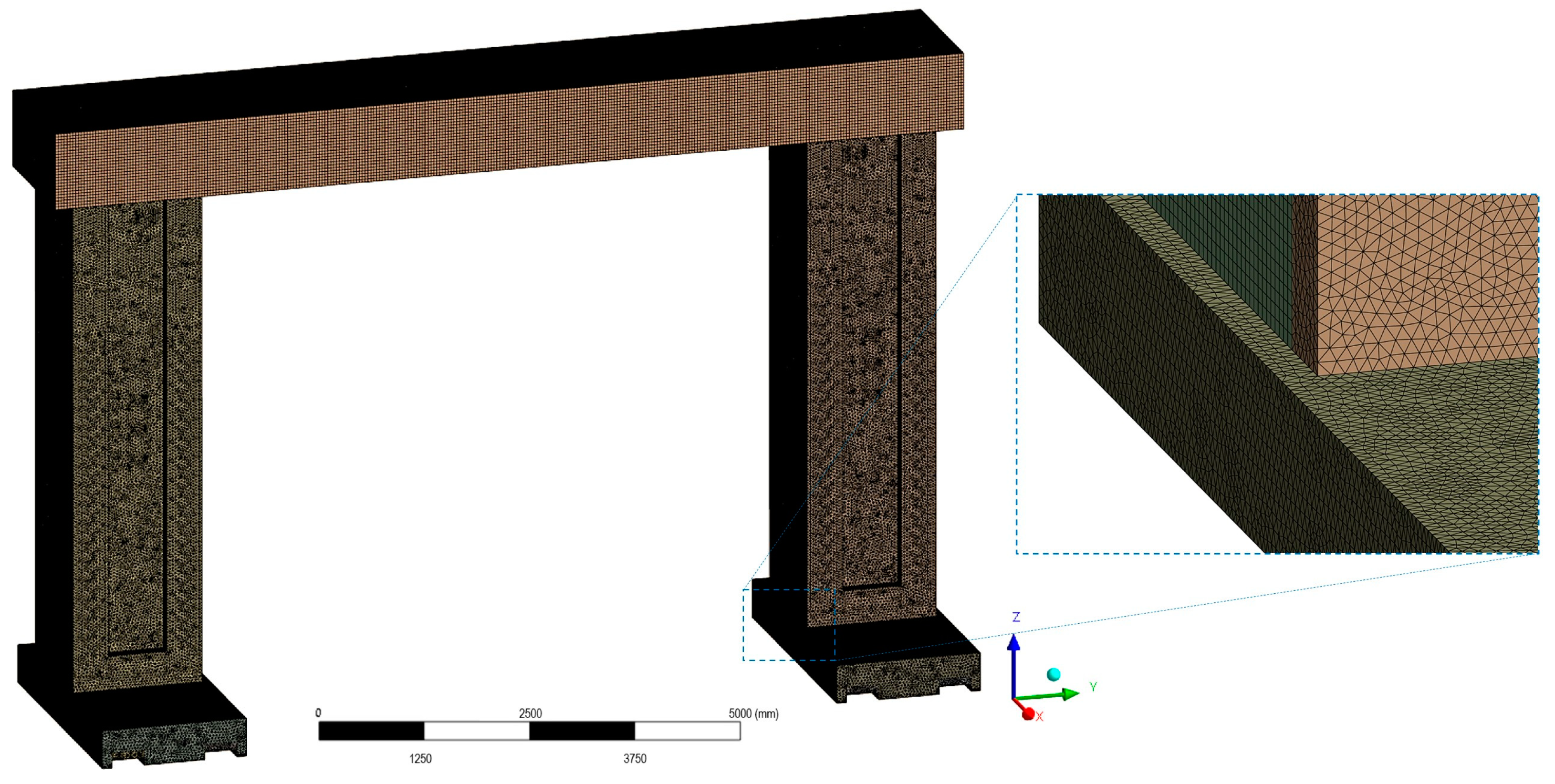
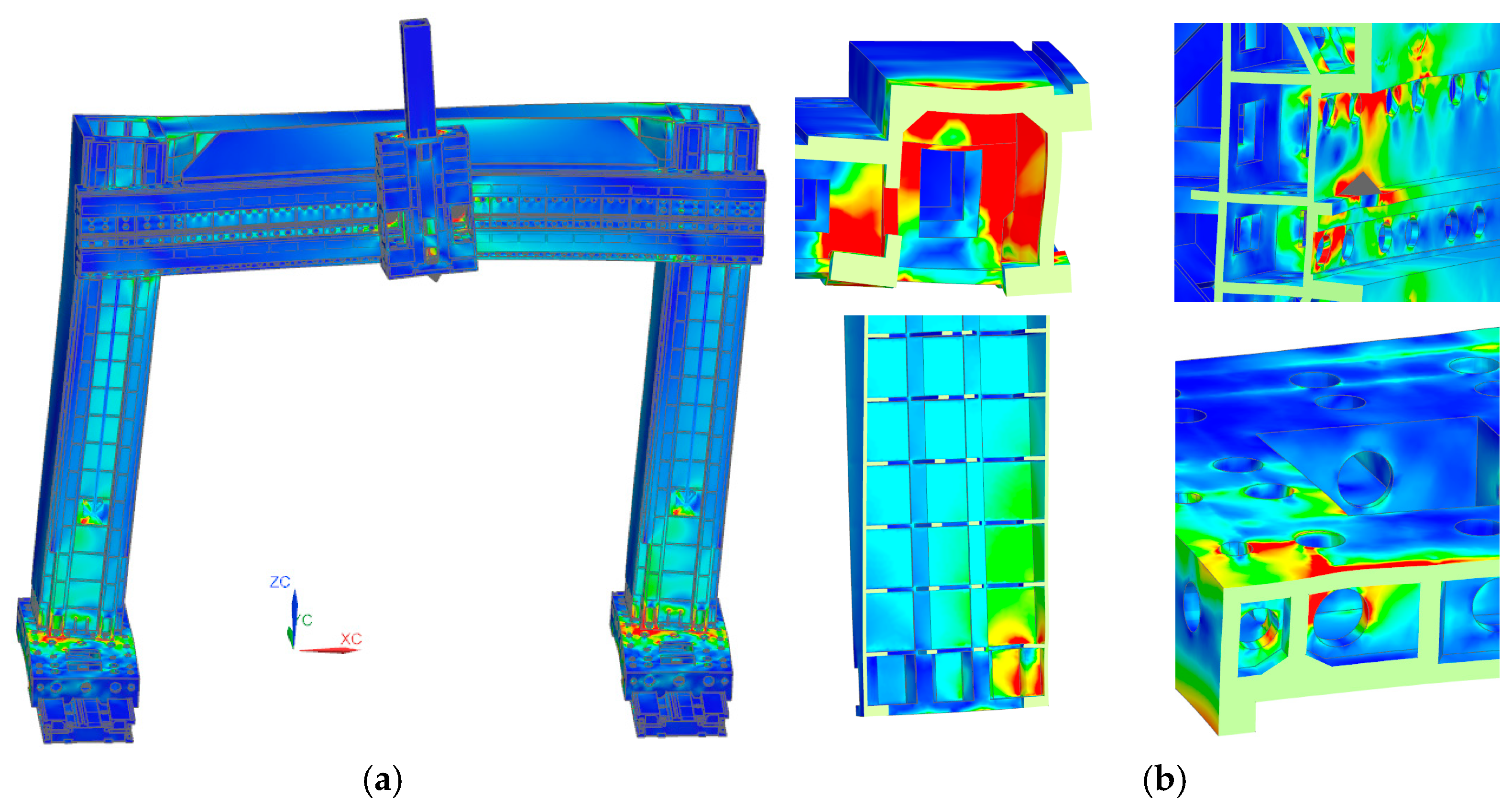
3.7. Stress and Stiffness Analysis
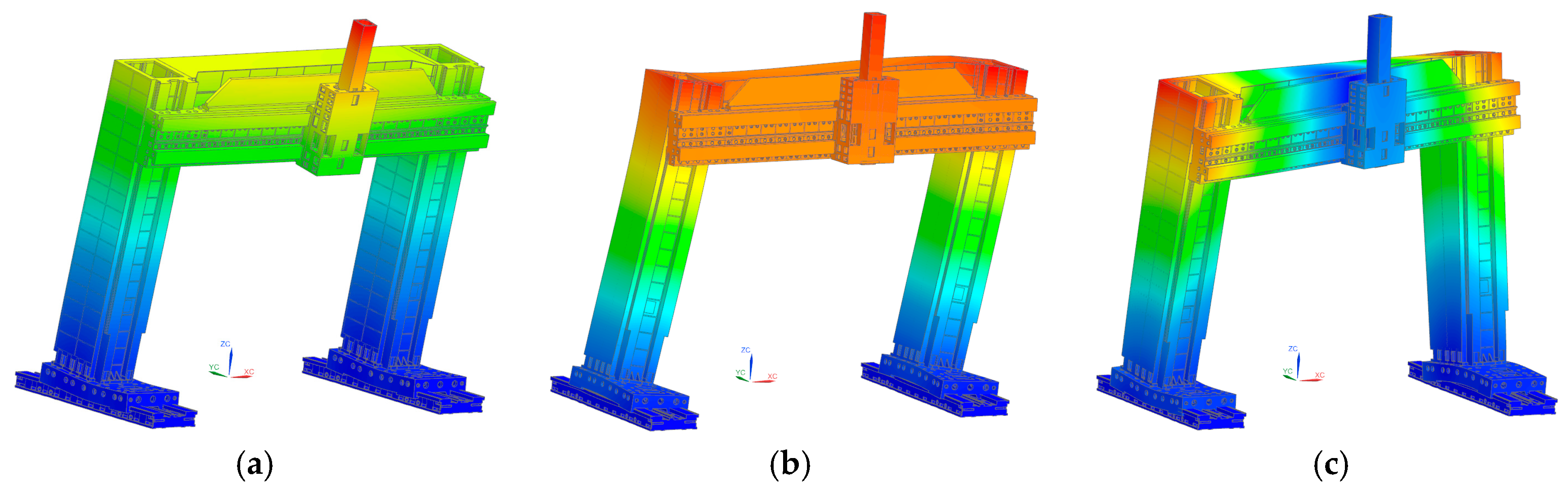
This is the next step of the proposed methodology (see H on Figure 2). The 3D model obtained from the TO was modified according to the manufacturing technology (the part will be designed as a casting). Therefore, a 3D model with technological details (E—see Figure 2) was used for stress and stiffness analyses. The model contained ribs with defined wall thicknesses, technological chamfers, etc. The boundary conditions (force and fixed constraints) were chosen similarly to the TO. The load spectrum was applied to the model. The cutting force of 40 kN in three basic directions was chosen for the load condition with maximum torque. Spring elements were applied at the point of the fixators. The stiffness of these elements was set to 6000 kN/mm in the normal direction and 500 kN/mm in the tangential direction based on previous research [29]. It was also necessary to define the guideway between the individual parts in the machine model. These were the guideway of the bottom of the column on the bed, the guideway of the cross-piece on the columns, the guideway of the headstock on the cross-piece, and the guideway of the slide in the headstock. In all cases, the hydrostatic guideway was used. It was idealised in the FEM model by elements of the contact type. This idealised the thickness of the film of the hydrostatic guideway as infinitely stiff. Furthermore, the feed mechanisms had to be idealised. The feed of the bottom of the column on the bed was solved by the MASTER-SLAVE system [52], the feed of the cross-piece on the column was solved by a ball screw, the feed of the headstock on the cross-piece was solved by the MASTER-SLAVE system, and the feed of the slide was solved by a pair of ball screws. The MASTER-SLAVE system was idealised using 1D elements with defined infinite stiffness, i.e., the ball screw using 1D spring elements with a defined stiffness (corresponding to the stiffness of the screw). The wall thicknesses of the individual parts (casting) were chosen according to the results of the TO. Greater wall thickness was selected in the bottom part of the column. Weak areas (with local stress peaks) were identified using stress analysis on this model. Adjustments were made to remove these stressed areas and the structure was analysed again. First, the whole portal assembly was analysed in terms of stiffness. Then, the section containing the headstock and slide was analysed to determine the behaviour of the machine at the location of the hydrostatic guideways. The results of the performed analyses can be found in Section 4.

3.8. Modal Analysis

This is the next step of the proposed methodology (see H on Figure 2). Modal analysis was performed to determine the behaviour of the structure in terms of dynamic loading and to optimise it. It was based on the theory of free vibration, where the general mathematical model of an oscillating system with one degree of freedom with viscous damping for free vibration is described by Equation (4):
q ¨ t + c q ˙ t + k q t = 0
where m is the mass matrix, c is the damping matrix, k is the stiffness matrix (these matrices are constant), and q is the generalised coordinate (deformation) [53]. Advanced simulation programs use FEM to determine the natural frequencies in most cases. The modal characteristics based on the shape and material of the element are determined following Equation (4). The harmonic oscillation is generally substituted into Equation (5), where Q is the column matrix of harmonic oscillation amplitudes and Ω is the angular frequency of the oscillation.
Q = Q · e i Ω t
After substitution and correction, Equation (6) is obtained:
( K 2 M ) · Q ¯ = 0
Eigen frequencies result from the condition of the zero determinant, which are described by Equation (7):
d e t K 2 M = 0
The natural frequency according to Equation (8) [54] is obtained as output in most FEM software:
f = / 2 π
The input to the modal analysis was a model identical to that used for the stress and stiffness analyses. The same boundary conditions were also applied to the model. The aim of the analysis was to determine the behaviour of the machine at excitation frequencies up to 50 Hz, corresponding to a maximum machine speed of 3000 rpm. The results are presented in Section 4. The orientation of the ribs was again modified based on the results in order to increase the natural frequencies of the machine.

3.9. Analytical Calculations

The design of the multifunctional portal machine required control calculations of its individual parts. These calculations included:
  • Guideways—Guideway of the bottom of the column on the bed, guideway of the cross-piece on the column, guideway of the spindle on the cross-piece, and guideway of the slide in the spindle.
  • Feed mechanisms—Feed of the bottom of the column on the bed, feed of the cross-piece on the column, feed of the spindle on the cross-piece, and feed of the slide in the spindle.
  • Screw connection
These analytical calculations were again used to optimise the dimensions of individual machine parts and their control.

3.10. MCD Simulations

This is the next step of the proposed methodology (see H on Figure 2). In our case, the Siemens NX-MCD software (Version 2000) tool was used only on the first level (see Figure 1). On this first level, the machine control system was not used and the model of the system was not created according to the SIL or HIL concept (SIMIT program was not used). The MCD tool allowed to simulate the sequential movements of the virtual model of the machine (including the weights of specific parts and inertial mass). The mechatronic model included the behaviour of actuators (position, speed, acceleration, and jerks). In the case of the portal centre, movements in directions X, Y, and Z were simulated, with the corresponding acceleration and with travel to the end positions of the machine. Furthermore, the change of machine accessories (milling and boring heads) was simulated. MCD simulations were performed continuously throughout all phases of the machine design. The created model and obtained results could be further used for possible virtual commissioning of the machine (see Section 6).

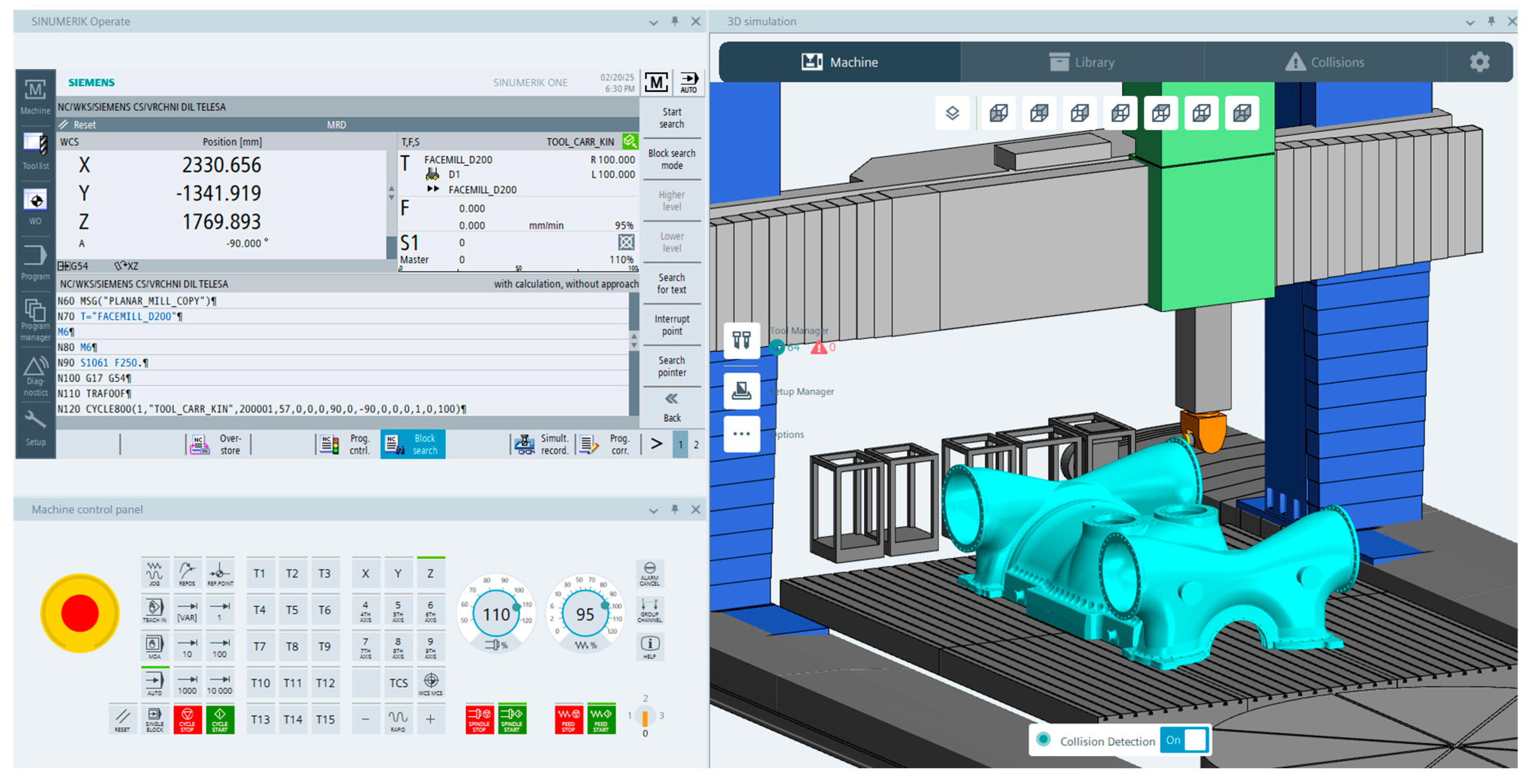
3.11. Machining Simulations of the Digital Twin of the CNC Machine Tool in Create MyVirtual Machine Software

This is the next step of the proposed methodology (see I on Figure 2). The main objective was to simulate the machining technology and prevent possible problems in the production of a specific part. In this case, machining simulations were used in the pre-production phase not only of the machined part itself but uniquely in the pre-production phase (design and development) of the entire production machine—the multifunctional portal centre. For the machining simulations, Create MyVirtual Machine 1.4.1.0 (CMVM) software was used. As input to the simulations, the NC code obtained from the postprocessor was used. The CMVM software allowed to virtually prepare the production on a digital twin of the machine with the same interface and interpolation as the real machine with the integration of the control system, namely, SINUMERIK ONE. In order to verify the technological characteristics (especially the dimensions) of the proposed machine, the following steps were necessary:
  • The kinematic model of the machine was developed in Create MyVirtual Machine 3D Builder 1.4.1.0 software.
  • In CMVM software, the real control system was linked to the machine kinematics.
  • The control system (SINUMERIK ONE) was configured for a given kinematic chain.
  • Tool exchange and tool management were implemented.
  • The machine kinematics were virtually compensated.
  • A 3D model of the workpiece and tools was imported.
  • The NC code generated by the postprocessor from the CAM tool was imported.
The utilisation of CMVM software is shown in Figure 10.
The virtual machine model of the multifunctional portal centre included accessories in the form of milling and turning heads, see Figure 11 and Figure 12.
Machining simulations (CMVM) were performed continuously throughout all phases of machine design.

4. Results

The multifunctional portal machine was designed according to the proposed methodology. Topology optimisation of the machine was performed at the beginning to find the most suitable material distribution in the main load-bearing parts of the machine (more precisely, the most suitable distribution of material flows that showed the most favourable stiffness-to-weight ratio). The result was the normalised material (the distribution of volume in the structure), where it was important (respecting the compliance of the structure). The envelopes of the final normalised material (including cross-sections in several areas) are shown in Figure 13.
The optimised volume was limited by the rough dimensions of the device that were chosen earlier. The resulting shape had to be modified for further analysis to respect the manufacturing technology of the parts (casting). Parts with defined wall thicknesses, ribs, and bevels were designed for subsequent stiffness and stress analyses. These detailed features were chosen precisely with regard to the results from the TO. Due to the complexity of the model and the calculation time, these details (part wall thickness and rib orientation) were not already applied to the model for TO. The results from the stress analysis are shown in Figure 14, specifically for the whole assembly of the machine (a) and for individual parts (b).
The stress is shown in the range from 0 to 2 MPa. Figure 14b shows the critical areas in the machine assembly where the model was subsequently optimised (dimensions, thicknesses, and rib orientation) and subjected to further analysis. The results from the stiffness analysis for the final shape of the structure can be seen in Table 3.
The table shows the displacement values at the tool location as well as the corresponding stiffness value in the three basic directions. The analysed stiffness was compared and evaluated with the help of the empirically obtained value of 50 kN/mm [28]. Modal analysis was subsequently performed to determine the behaviour of the portal machine under dynamic loading. The natural frequencies up to 50 Hz were found. This corresponded to a machine speed limit of 3000 rpm. The values for the first twenty natural frequencies are shown in Table 4.
The mode shapes belonging to the first (a) and second natural frequency (b) had primarily a bending character, while the third natural frequency (c) had a torsion character, see Figure 15. The corresponding colours indicate the displacement of the particular parts of the model (blue—the smallest value, red—the largest value).
The other natural frequencies oscillated either by a combination of bending and torsion or they were the mode shapes of the component parts of the machine (e.g., spindle, ball screw, cross piece, etc.). The dimensions of the machine were again optimised based on the results of the modal analysis. The ribs and wall thicknesses in the exposed areas of the structure were modified.
MCD and machining simulations were performed continuously throughout all phases of machine design. MCD simulations were used to verify the machine dimensions and configuration of the drives, including the simulation of end positions. The resulting mechatronic concept was then used for virtual machine commissioning in the software in the loop concept, where a digital twin of the machine was also used. The machining simulations with integration of the control system verified the technological characteristics of the machine. These were, namely, the kinematics of the machine tool, i.e., the suitability of its dimensions for machining specific parts. The machining simulations further verified the manufacturability of specific parts, including the use of accessories (carousel table, milling heads, etc.). Collisions and part production time were predicted. The final parameters based on the performed analyses and simulations are given in Table 5.
The final dimensions (and the overall dimensions and shape of the individual machine tool parts) were determined using the proposed methodology though the following procedure:
  • The rough dimensions were chosen;
  • The main dimensions and especially the shape and internal dimensions of individual parts were optimised using the topology optimisation;
  • The dimensions were optimised using the stress analysis;
  • The dimensions were optimised using the stiffness analysis using the empirical stiffness value;
  • The dimensions were optimised using the modal analysis;
  • The dimensions were optimised using analytical calculations;
  • MCD simulations were used to optimise the main dimensions in relation to the kinematics of the machine and the travel in each axis;
  • The machining simulations (using the digital twin) verified the following dimensions in terms of the minimum values that were required for machining a given set of workpieces.
The final shape and dimensions of the portal machine were designed based on the simulations and calculations performed in the previous sections and are shown in Figure 16.

5. Discussion

The aim of this research was to propose a methodology intended for the design of a portal machine centre that would appropriately combine the application of the previously mentioned methods and would be generally applicable to the development of other machine tools. The outputs from the various analyses thus were used as inputs to subsequent analyses with the aim of progressively optimising the portal machine. Although no publications were found dealing with the methodology of the application of a suitable combination of CAx tools for machine tool development, it was possible to use the findings from research on the various methods. The individual analyses performed in this research were solved in accordance with previously published data, especially in the creation of the digital twin of the machine. First of all, it was necessary to select representative workpieces and technological operations. TO was used for the model with the proposed rough dimensions of the machine. During the development of the model for TO, the available resources were used for the design of the mesh, the selection of boundary conditions, and the definition of objective functions. At the same time, a CAM program and postprocessor were performed to obtain the input data for the simulations of the digital twin. The input to the TO was a model with rough dimensions with full volume. This model did not contain ribs and technological details to minimise computational time. For the purpose of the subsequent stiffness and stress calculations, the resulting model had to be modified to respect the manufacturing technology of the casting. Therefore, wall thicknesses, chamfers, and ribs were oriented specifically with respect to the results from the TO and manufacturing technology. Stiffness, stress, and modal analyses were performed on the modified model. The mesh creation and selection of boundary conditions again corresponded with the available articles. The limit value of 50 kN/mm was verified for the stiffness analysis. This value was empirically chosen based on experience at the company ŠMT a.s. and also corresponded with the available references [28]. The results of all of these simulations were very important to determine the final dimensions of the machine. CAD models were modified based on the results and were used as input to subsequent MCD and machining simulations. A digital twin of the machine (one of the key elements of Industry 5.0) was used to perform the machining simulations and to verify the functionality of the developed machine. The results obtained from the numerical analyses were verified using MCD simulations and simulations of the digital twin of the machine. The machining simulations were also used to verify that the representative workpieces could be safely machined on a machine with the proposed dimensions, with specific tools and specific accessories. The proposed methodology allows for optimisation of the dimensions of any proposed machine and subsequent verification of these dimensions through machining simulations of specific parts. The computational time for stiffness and stress analysis was in the order of tens of hours and even in the order of days for modal analysis and TO. The computational difficulty was determined by the complexity of the individual parts of the model, the fineness of the mesh, and the utilisation of contact elements. The possibility of algorithising the whole methodology seems to be a suitable area for further research. This process would include exporting and importing CAD models between analyses and automatically processing the results.
A number of articles have been found dealing with the utilisation of CAx tools [24,25] in machine tool development. In most cases, these tools have been used separately, namely, CAD tools for model creation, CAE tools for advanced simulations [8,11,26,28,29,55,56], CAM tools (CAM for machining simulations [27]), or tools using digital twin [13,42] (MCD for mechatronic concepts [41]). Some of these aforementioned studies [11,26,27,28,29,30,32] have verified these tools separately. The mentioned articles [30,31,32] dealt with the integration of digital twins at some stage of machine development. None of the articles presented a methodology that dealt with the integration of optimisation calculations in the early stages of machine design and with the integration of digital twins to determine the optimal technological properties of the machine tool (especially the dimensions) with respect to the key principles of Industry 5.0. This is a major innovation of the newly proposed methodology.

6. Future Work

For the future virtual commissioning of the portal milling machine, a digital twin will be used in the SIL or HIL concept (second level in Figure 1). The HIL concept has been tested in previous projects [41]. The following steps are required to implement virtual commissioning (using the HIL concept):
  • Creation of MCD models in NX mechatronic concept designer (bodies, joints, actuators, signals);
  • Setting up the SINUMERIK control system (installation of ADAS compile cycle, setting up simulation axes, disabling SAFETY INTEGRATED, etc.);
  • Setting up LAN communication between PC and SIMIT UNIT;
  • Setting up the HW configuration in SIMATIC Manager (adding ADAS);
  • Creating a program in SIMATIC Manager;
  • Creating a project in SIMIT software (mapping ProfiNET signals to Share Memory);
  • Mapping signals between MCD and SIMIT software.
An example of signal mapping between MCD and SIMIT Share Memory (with specific data type) is shown in Figure 17.
In addition to signals for motion control, signals for controlling the travel of the cabin or head change are also addressed. SIMIT uses the ADAS build cycle to map the drive control signals, see Figure 18.
To enable this cycle, specific settings are required in the SINUMERIK control system. In the case of using the HIL concept, the finished virtual model obtained from NX MCD simulations (first level) would be used. In the case of the SIL concept, the CMVM program itself would be used. In this case, the same tool (CMVM) would be used as for the machining simulations of the digital twin of the CNC machine tool (see next section), which is a great advantage. The main benefits of these concepts are the verification of the proposed methodology and verification based on real machine behaviour (e.g., signals, sensors, and transducers).

7. Conclusions

The methodology for the development of a machine tool was proposed. It was applied on a multifunctional portal centre. The methodology included the selection of representative workpieces and technological operations, a sequence of numerical analyses, and simulations using the digital twin. The shape and dimensions of the proposed portal machine were optimised based on the performed analyses. The simulations on the digital twin also aimed to optimise the dimensions and, in a further phase, to verify the machinability of a specific workpiece on the proposed machine, thus validating the proposed methodology. The machining simulations were used to verify the machine kinematics, collision prediction, and production time. Furthermore, the solution resulted in optimised machine dimensions and optimised shape. By optimising the dynamic characteristics of the machine, vibration and noise were reduced, thus reducing the negative impact on the machine operator. The proposed methodology fulfilled the key principles of Industry 4.0 (resp. 5.0) by using the key elements, namely, computer support for all phases of the product life cycle (CAx) and the utilisation of digital twin technology. The main benefit of this research was to increase the useful properties of the developed machine tool, namely, increasing the stiffness, reducing the energy requirements of equipment, reducing the weight, increasing the power, or using alternative materials. It is also applicable in the development of other machine tools. The proposed methodology will allow (through a wide range of optimisations and interconnection of CAx systems) to obtain a more fair and sustainable society in which there is symbiosis between operators and machines. The key advantage of the proposed methodology is obtaining the optimal technological properties of a machine tool. The obtained outputs will be used in the future for the virtual commissioning of the real machine and to verify the methodology. The application of the proposed methodology with the SIL concept (mutual integration of MCD simulations, SIMIT software, and CMVM) will be the object of further research. Simulations with the SIL concept will (compared to the HIL concept) be performed only on a virtual basis without any interaction with the real hardware of the machine. As a result, an earlier prediction of machine properties is expected, as well as lower hardware and financial complexity of the whole process. Integration with NX MCD simulations will also have the advantage of a unified software environment for machine design, machine optimisation, and digital twin creation.

Author Contributions

Conceptualization, P.B. and P.J.; data curation, P.B. and F.S.; formal analysis, P.B. and F.S.; funding acquisition, P.B., V.L. and J.K. (Jiri Kubicek); investigation, P.B. and F.S.; methodology, P.B.; project administration, P.B., V.L. and J.K. (Jiri Kubicek); resources, P.B. and J.K. (Josef Kozak); software, P.B., Z.H. and P.J.; supervision, P.B.; validation, P.B., Z.H. and P.J.; visualization, P.B. and J.K. (Josef Kozak); writing—original draft, P.B., Z.H., P.J. and J.K. (Josef Kozak); writing—review & editing, P.B. and J.K. (Josef Kozak). All authors have read and agreed to the published version of the manuscript.

Funding

This project (TREND–FW06010259) was funded by Technology Agency of the Czech Republic and the Ministry of Industry and Trade of the Czech Republic.

Institutional Review Board Statement

Not applicable.

Informed Consent Statement

Not applicable.

Data Availability Statement

The original contributions presented in this study are included in the article. Further inquiries can be directed to the corresponding authors.

Acknowledgments

This project (grant number FW06010259) was financed by state support from the Technology Agency of the Czech Republic and the Ministry of Industry and Trade of the Czech Republic within the TREND Programme.
Applsci 15 03312 i001

Conflicts of Interest

The authors declare no conflicts of interest.

References

  1. Paschek, D.; Luminosu, C.-T.; Ocakci, E. Industry 5.0 Challenges and Perspectives for Manufacturing Systems in the Society 5.0. In Sustainability and Innovation in Manufacturing Enterprises: Indicators, Models and Assessment for Industry 5.0; Draghici, A., Ivascu, L., Eds.; Springer: Singapore, 2022; pp. 17–63. ISBN 9789811673658. [Google Scholar]
  2. Kusiak, A. Smart Manufacturing. Int. J. Prod. Res. 2018, 56, 508–517. [Google Scholar] [CrossRef]
  3. Dittrich, M.-A.; Denkena, B.; Boujnah, H.; Uhlich, F. Autonomous Machining—Recent Advances in Process Planning and Control. J. Mach. Eng. 2019, 19, 28–37. [Google Scholar] [CrossRef]
  4. Shirase, K.; Nakamoto, K. Simulation Technologies for the Development of an Autonomous and Intelligent Machine Tool. Int. J. Autom. Technol. 2013, 7, 6–15. [Google Scholar] [CrossRef]
  5. Ahmad, R.; Tichadou, S.; Hascoet, J.-Y. Generation of Safe and Intelligent Tool-Paths for Multi-Axis Machine-Tools in a Dynamic 2D Virtual Environment. Int. J. Comput. Integr. Manuf. 2016, 29, 982–995. [Google Scholar] [CrossRef]
  6. Ahmad, R.; Tichadou, S.; Hascoet, J.-Y. 3D Safe and Intelligent Trajectory Generation for Multi-Axis Machine Tools Using Machine Vision. Int. J. Comput. Integr. Manuf. 2013, 26, 365–385. [Google Scholar] [CrossRef]
  7. Lu, Y.; Xu, X.; Wang, L. Smart Manufacturing Process and System Automation—A Critical Review of the Standards and Envisioned Scenarios. J. Manuf. Syst. 2020, 56, 312–325. [Google Scholar] [CrossRef]
  8. Chang, K.-H. E-Design: Computer-Aided Engineering Design; Academic Press: Cambridge, MA, USA, 2016; ISBN 978-0-12-809736-6. [Google Scholar]
  9. Gubbi, J.; Buyya, R.; Marusic, S.; Palaniswami, M. Internet of Things (IoT): A Vision, Architectural Elements, and Future Directions. Future Gener. Comput. Syst. 2013, 29, 1645–1660. [Google Scholar] [CrossRef]
  10. Buxmann, P.; Hess, T.; Ruggaber, R. Internet of Services. Bus. Inf. Syst. Eng. 2009, 1, 341–342. [Google Scholar] [CrossRef]
  11. Ráž, K.; Chval, Z.; Štěpánek, M.; Vyhnal, O. Mechanical Analysis of the Newly Developed 3D Printed Prosthetic Socket from PA12GB. MM Sci. J. 2022, 11, 6064–6068. [Google Scholar] [CrossRef]
  12. Gokalp, M.O.; Kayabay, K.; Akyol, M.A.; Eren, P.E.; Koçyiğit, A. Big Data for Industry 4.0: A Conceptual Framework. In Proceedings of the 2016 International Conference on Computational Science and Computational Intelligence (CSCI), Las Vegas, NV, USA, 15–17 December 2016; pp. 431–434. [Google Scholar]
  13. Gallala, A.; Kumar, A.A.; Hichri, B.; Plapper, P. Digital Twin for Human–Robot Interactions by Means of Industry 4.0 Enabling Technologies. Sensors 2022, 22, 4950. [Google Scholar] [CrossRef]
  14. Qian, L.; Luo, Z.; Du, Y.; Guo, L. Cloud Computing: An Overview. In Cloud Computing, Proceedings of the First International Conference, CloudCom 2009, Beijing, China, 1–4 December 2009; Jaatun, M.G., Zhao, G., Rong, C., Eds.; Springer: Berlin/Heidelberg, Germany, 2009; pp. 626–631. [Google Scholar]
  15. Hunt, E.B. Artificial Intelligence; Academic Press: Cambridge, MA, USA, 2014; ISBN 978-1-4832-6317-5. [Google Scholar]
  16. Xu, X.; Lu, Y.; Vogel-Heuser, B.; Wang, L. Industry 4.0 and Industry 5.0—Inception, Conception and Perception. J. Manuf. Syst. 2021, 61, 530–535. [Google Scholar] [CrossRef]
  17. Coelho, P.; Bessa, C.; Landeck, J.; Silva, C. Industry 5.0: The Arising of a Concept. Procedia Comput. Sci. 2023, 217, 1137–1144. [Google Scholar] [CrossRef]
  18. Čechura, M.; Hlaváč, J.; Chval, Z.; Kubec, V. Přínosy řešení nových prototypů tvářecích strojů navržených CVTS na ZČU v Plzni se Šmeral Brno a.s. a TS Plzeň a.s. Benefits of solving new prototypes of forming machines designed by CVTS at UWB in Pilsen with Šmeral Brno a.s. and TS Plzeň a.s. Kovárenství 2019, 68, 79–83. [Google Scholar]
  19. Morgan, J.; Halton, M.; Qiao, Y.; Breslin, J.G. Industry 4.0 Smart Reconfigurable Manufacturing Machines. J. Manuf. Syst. 2021, 59, 481–506. [Google Scholar] [CrossRef]
  20. Xu, X. Machine Tool 4.0 for the New Era of Manufacturing. Int. J. Adv. Manuf. Technol. 2017, 92, 1893–1900. [Google Scholar] [CrossRef]
  21. Lee, E.A. CPS Foundations. In Proceedings of the 47th Design Automation Conference, Anaheim, CA, USA, 13–18 July 2010; Association for Computing Machinery: New York, NY, USA, 2010; pp. 737–742. [Google Scholar]
  22. Derler, P.; Lee, E.; Sangiovanni-Vincentelli, A. Modeling Cyber-Physical Systems. Proc. IEEE 2012, 100, 13–28. [Google Scholar] [CrossRef]
  23. Altintas, Y.; Brecher, C.; Weck, M.; Witt, S. Virtual Machine Tool. CIRP Ann. 2005, 54, 115–138. [Google Scholar] [CrossRef]
  24. Lee, K. Principles of CAD/CAM/CAE Systems; Addison-Wesley Longman Publishing Co., Inc.: Boston, MA, USA, 1999; ISBN 978-0-201-38036-1. [Google Scholar]
  25. Werner Dankwort, C.; Weidlich, R.; Guenther, B.; Blaurock, J.E. Engineers’ CAx Education—It’s Not Only CAD. Comput.-Aided Des. 2004, 36, 1439–1450. [Google Scholar] [CrossRef]
  26. Janda, P.; Polák, R. Virtual Prototyping and Optimization of Heavy Machine Tools. In Proceedings of the 26th DAAAM International Symposium on Intelligent Manufacturing and Automation, Zadar, Croatia, 18–25 October 2015; pp. 0967–0973, ISBN 978-3-902734-07-5. [Google Scholar]
  27. Hajicek, Z.; Marek, V. Simulation of Virtual Machine Tool During the Machine Design. In DAAAM Proceedings, Proceedings of the 28th DAAAM International Symposium on Intelligent Manufacturing and Automation, Zadar, Croatia, 8–11 November 2017; Katalinic, B., Ed.; DAAAM International: Vienna, Austria, 2017; Volume 1, pp. 0555–0560. ISBN 978-3-902734-11-2. [Google Scholar]
  28. Lasova, V.; Bernardin, P.; Švagr, M.; Kubicek, J. Alternative Solution of A Milling Head Housing Using the Computer Aided Systems. MM Sci. J. 2021, 2021, 4304–4309. [Google Scholar] [CrossRef]
  29. Sedláček, F.; Lasova, V.; Bernardin, P.; Janda, P.; Švagr, M. Optimization of Main Parts of a Heavy Duty CNC Machine Centre Using a Topological Optimization. In Proceedings of the 30th DAAAM International Symposium on Intelligent Manufacturing and Automation, Zadar, Croatia, 23–26 October 2019; pp. 0525–0532, ISBN 978-3-902734-22-8. [Google Scholar]
  30. Lo, C.K.; Chen, C.H.; Zhong, R.Y. A Review of Digital Twin in Product Design and Development. Adv. Eng. Inform. 2021, 48, 101297. [Google Scholar] [CrossRef]
  31. Meng, Z.; Guoxi, L. Digital Twinning Method Based on Multi-Model Integration and Interoperation. In Proceedings of the 2024 3rd International Conference on Innovations and Development of Information Technologies and Robotics (IDITR), Hong Kong, 23–25 May 2024; pp. 183–188. [Google Scholar]
  32. Gusev, M.P.; Nikolaev, S.M.; Uzhinsky, I.K.; Padalitsa, D.I.; Mozhenkov, E.R. Application of Optimization in the Early Stages of Product Development, Using a Small UAV Case Study. In Product Lifecycle Management to Support Industry 4.0, Proceedings of the 15th IFIP WG 5.1 International Conference, PLM 2018, Turin, Italy, 2–4 July 2018; Chiabert, P., Bouras, A., Noël, F., Ríos, J., Eds.; Springer International Publishing: Cham, Switzerland, 2018; pp. 294–303. [Google Scholar]
  33. Kenett, R.S.; Bortman, J. The Digital Twin in Industry 4.0: A Wide-Angle Perspective. Qual. Reliab. Eng. Int. 2022, 38, 1357–1366. [Google Scholar] [CrossRef]
  34. Onaji, I.; Tiwari, D.; Soulatiantork, P.; Song, B.; Tiwari, A. Digital Twin in Manufacturing: Conceptual Framework and Case Studies. Int. J. Comput. Integr. Manuf. 2022, 35, 831–858. [Google Scholar] [CrossRef]
  35. Sim, B.; Lee, W. Digital Twin Based Machining Condition Optimization for CNC Machining Center. Int. J. Precis. Eng. Manuf.-Smart Tech. 2023, 1, 115–123. [Google Scholar] [CrossRef]
  36. Zhang, K.; Ding, Z. Virtual Simulation Design and Debugging of Lift-and-Transverse Stereo Garage Based on the Digital Twin. Appl. Sci. 2024, 14, 3896. [Google Scholar] [CrossRef]
  37. Schacht, J.; Wölk, A.; Pingel, S.; Herbst, U.; Naujoks, D. Simulation System for the Wendelstein 7-X Safety Control System. IEEE Trans. Nucl. Sci. 2019, 66, 1262–1266. [Google Scholar] [CrossRef]
  38. Oppelt, M.; Wolf, G.; Urbas, L. Towards an Integrated Use of Simulation within the Life-Cycle of a Process Plant. In Proceedings of the 2015 IEEE 20th Conference on Emerging Technologies & Factory Automation (ETFA), Luxembourg, 8–11 September 2015; pp. 1–8. [Google Scholar]
  39. Kopček, M.; Križanová, G.; Ružarovský, R. A Brief Survey of Creating a Digital Twin Architecture for Virtual Commissioning on the Machine Level. Res. Pap. Fac. Mater. Sci. Technol. Slovak Univ. Technol. 2022, 30, 71–80. [Google Scholar] [CrossRef]
  40. Bargiela, A.; Ali, S.A.; Crowley, D.; Kerckhoffs, E.J.H. Proceedings of the 24th European Conference on Modelling and Simulation, Kuala Lumpur, Malaysia, 1–4 June 2010; ECMS Press: Hong Kong, China, 2010; ISBN 978-0-9564944-0-5. [Google Scholar]
  41. Janda, P. Mechatronic Concept of Heavy Machine Tools; DAAAM: Vienna, Austria, 2018; ISBN 978-3-902734-20-4. [Google Scholar]
  42. Janda, P.; Hájíček, Z.; Bernardin, P. Implementation of The Digital Twin Methodology. In Proceedings of the 30th DAAAM International Symposium on Intelligent Manufacturing and Automation, Zadar, Croatia, 23–26 October 2019; pp. 0533–0538, ISBN 978-3-902734-22-8. [Google Scholar]
  43. Rao, S.S. The Finite Element Method in Engineering; Butterworth-Heinemann: Oxford, UK, 2017; ISBN 978-0-12-814364-3. [Google Scholar]
  44. Querin, O.M.; Young, V.; Steven, G.P.; Xie, Y.M. Computational Efficiency and Validation of Bi-Directional Evolutionary Structural Optimisation. Comput. Methods Appl. Mech. Eng. 2000, 189, 559–573. [Google Scholar] [CrossRef]
  45. Querin, O.M.; Steven, G.P.; Xie, Y.M. Evolutionary Structural Optimisation Using an Additive Algorithm. Finite Elem. Anal. Des. 2000, 34, 291–308. [Google Scholar] [CrossRef]
  46. Xie, Y.M.; Huang, X. Recent Developments in Evolutionary Structural Optimization (ESO) for Continuum Structures. IOP Conf. Ser. Mater. Sci. Eng. 2010, 10, 012196. [Google Scholar] [CrossRef]
  47. Beckers, M.; Fleury, C. Topology Optimization Involving Discrete Variables; Polish Academy of Sciences, Institute of Fundamental Technological Research: Warsaw, Poland, 1997. [Google Scholar]
  48. Allaire, G. The Homogenization Method for Topology and Shape Optimization. In Topology Optimization in Structural Mechanics; Rozvany, G.I.N., Ed.; Springer: Vienna, Austria, 1997; pp. 101–133. ISBN 978-3-7091-2566-3. [Google Scholar]
  49. Stolpe, M.; Svanberg, K. An Alternative Interpolation Scheme for Minimum Compliance Topology Optimization. Struct. Multidisc. Optim. 2001, 22, 116–124. [Google Scholar] [CrossRef]
  50. Bendsøe, M.P. Optimal Shape Design as a Material Distribution Problem. Struct. Optim. 1989, 1, 193–202. [Google Scholar] [CrossRef]
  51. Zhou, M.; Rozvany, G.I.N. The COC Algorithm, Part II: Topological, Geometrical and Generalized Shape Optimization. Comput. Methods Appl. Mech. Eng. 1991, 89, 309–336. [Google Scholar] [CrossRef]
  52. Sakata, K.; Fujimoto, H. Master-Slave Synchronous Position Control for Precision Stages Based on Multirate Control and Dead-Time Compensation. In Proceedings of the 2009 IEEE/ASME International Conference on Advanced Intelligent Mechatronics, Singapore, 14–17 July 2009; pp. 263–268. [Google Scholar]
  53. Okubo, N.; Yoshida, Y.; Hoshi, T. Application of Modal Analysis to Machine Tool Structures. CIRP Ann. 1982, 31, 243–246. [Google Scholar] [CrossRef]
  54. Zeman, V.; Hlaváč, Z. Kmitání Mechanických Soustav, 2nd ed.; Západočeská Univerzita: Plzeň, Czech Republic, 2004; ISBN 807043337X. [Google Scholar]
  55. Huang, D.T.-Y.; Lee, J.-J. On Obtaining Machine Tool Stiffness by CAE Techniques. Int. J. Mach. Tools Manuf. 2001, 41, 1149–1163. [Google Scholar] [CrossRef]
  56. Lianqing, Y.; Liping, W. Stiffness Analysis of Machine Tools Using Finite Element Method. In Proceedings of the 2009 Third International Symposium on Intelligent Information Technology Application, Nanchang, China, 21–22 November 2009; Volume 3, pp. 553–556. [Google Scholar]
Figure 1. Closed loop engineering system (hardware and software in the loop).
Applsci 15 03312 g001
Figure 2. Methodology of using CAx and the digital twin of the multifunctional portal centre in its pre-production phase.
Applsci 15 03312 g002
Figure 3. Representative workpieces—welded structure (a), and the propeller blade (b).
Applsci 15 03312 g003
Figure 4. Representative workpieces—the steam generator body ring (a) and the turbine body (b).
Applsci 15 03312 g004
Figure 5. The nomenclature of machine tool axes.
Applsci 15 03312 g005
Figure 6. Three-dimensional model of the rough dimensions of the multifunctional portal machine (a), and scheme with rough dimensions of the machine (b).
Applsci 15 03312 g006
Figure 7. Meshed 3D model of the portal part with defined force and fixed constraints.
Applsci 15 03312 g007
Figure 8. Input load cases for topology optimisation. (a) Topology optimisation—Load Case I. (b) Topology optimisation—Load Case II.
Applsci 15 03312 g008
Figure 9. Siemens NX CAM tool with developed NC code.
Applsci 15 03312 g009
Figure 10. The utilisation of CMVM software.
Applsci 15 03312 g010
Figure 11. CNC universal milling head (a), and turning head (b).
Applsci 15 03312 g011
Figure 12. Right angle milling head (a), and extension milling head (b).
Applsci 15 03312 g012
Figure 13. The resulting volume distribution obtained from topology optimisation.
Applsci 15 03312 g013
Figure 14. The results of the stiffness and stress analyses of the whole assembly of the machine (a) and of individual parts (b).
Applsci 15 03312 g014
Figure 15. The mode shapes belonging to the first three natural frequencies.
Applsci 15 03312 g015
Figure 16. Final dimensions of the multifunctional gantry machine.
Applsci 15 03312 g016
Figure 17. Signal mapping in NX Mechatronic concept designer software.
Applsci 15 03312 g017
Figure 18. ADAS compile cycles setting.
Applsci 15 03312 g018
Table 1. Basic parameters of the multifunctional portal centre.
ParameterUnitHigh Speed SolutionHigh Torque Solution
Power[kW]119
Spindle speed[rpm]40003000
Torque[Nm]30008500
Clearance under spindle[mm]70007000
Clearance between column[mm]90009000
X (Gantry)—axis[mm]n × 2000
Y (Headstock)—axis[mm]10,000
Z (Ram)—axis[mm]2000
W (Cross-piece)—axis[mm]5000
Feed rates[mm/min]0.5–15,000
Ram extension[mm]2000
Table 2. Load spectrum with derived cutting parameters.
ToolWorkpiece/Tool DiameterPowerCutting TorqueCutting Force
Cutting unit C10-PSRNL-58110-25190 mm34.9 kW7690 Nm40 kN
Square shoulder milling cutter A490-254R63-14M254 mm96.3 kW6270 Nm24.6 kN
Square shoulder milling cutter R390-160Q40-18L160 mm48 kW1360 Nm8.5 kN
Face milling cutter 345-100Q32-13H100 mm30.3 kW431 Nm4.3 kN
Square shoulder milling cutter 490-050C5-08M50 mm16.6 kW110 Nm2.2 kN
Solid carbide end mill 1K223-2000-050-NH H10F20 mm31.8 kW14.9 Nm0.75 kN
Solid carbide end mill 1K212-0200-XA 17302 mm0.09 kW0.0381 Nm0.02 kN
Face disc milling cutter R331.32-315Q60RM23.50315 mm23.2 kW1438 Nm8 kN
Table 3. Table of the resulting displacement and stiffness at the tool position for the final shape of the machine.
ParameterStiffness of Fixators
(Normal/Tangential)
Displacement
XYZXYZ
Displacement in the tool position6000/500 kN/mm0.319 mm0.374 mm0.184 mm0.525 mm
Stiffness in the tool position125.4 kN/mm107 kN/mm217.4 kN/mm
Table 4. The values for the first twenty natural frequencies.
Natural
Frequency
ValueUnitsNatural
Frequency
ValueUnitsNatural
Frequency
ValueUnitsNatural
Frequency
ValueUnits
1.4.3Hz6.22.4Hz11.35.6Hz16.38.8Hz
2.4.5Hz7.27.6Hz12.36.7Hz17.39.5Hz
3.8.5Hz8.28.7Hz13.37.1Hz18.40.4Hz
4.16.4Hz9.31.3Hz14.37.5Hz19.48.8Hz
5.19.8Hz10.31.7Hz15.38.0Hz20.49.7Hz
Table 5. The dimensions of the multifunctional portal centre obtained from performed analyses and simulations.
X (Headstock)—axis10,000 mm
Y (Gantry)—axis21,000 mm
Z (Ram)—axis2500 mm
W (Cross-piece)—axis3500 mm
Disclaimer/Publisher’s Note: The statements, opinions and data contained in all publications are solely those of the individual author(s) and contributor(s) and not of MDPI and/or the editor(s). MDPI and/or the editor(s) disclaim responsibility for any injury to people or property resulting from any ideas, methods, instructions or products referred to in the content.

