Numerical Simulation of an Optical Resonator for the Generation of Radial Laguerre–Gauss LGp0 Modes


Abstract
1. Introduction
2. Single-Pass and Multi-Pass Properties of Binary Amplitude Masks
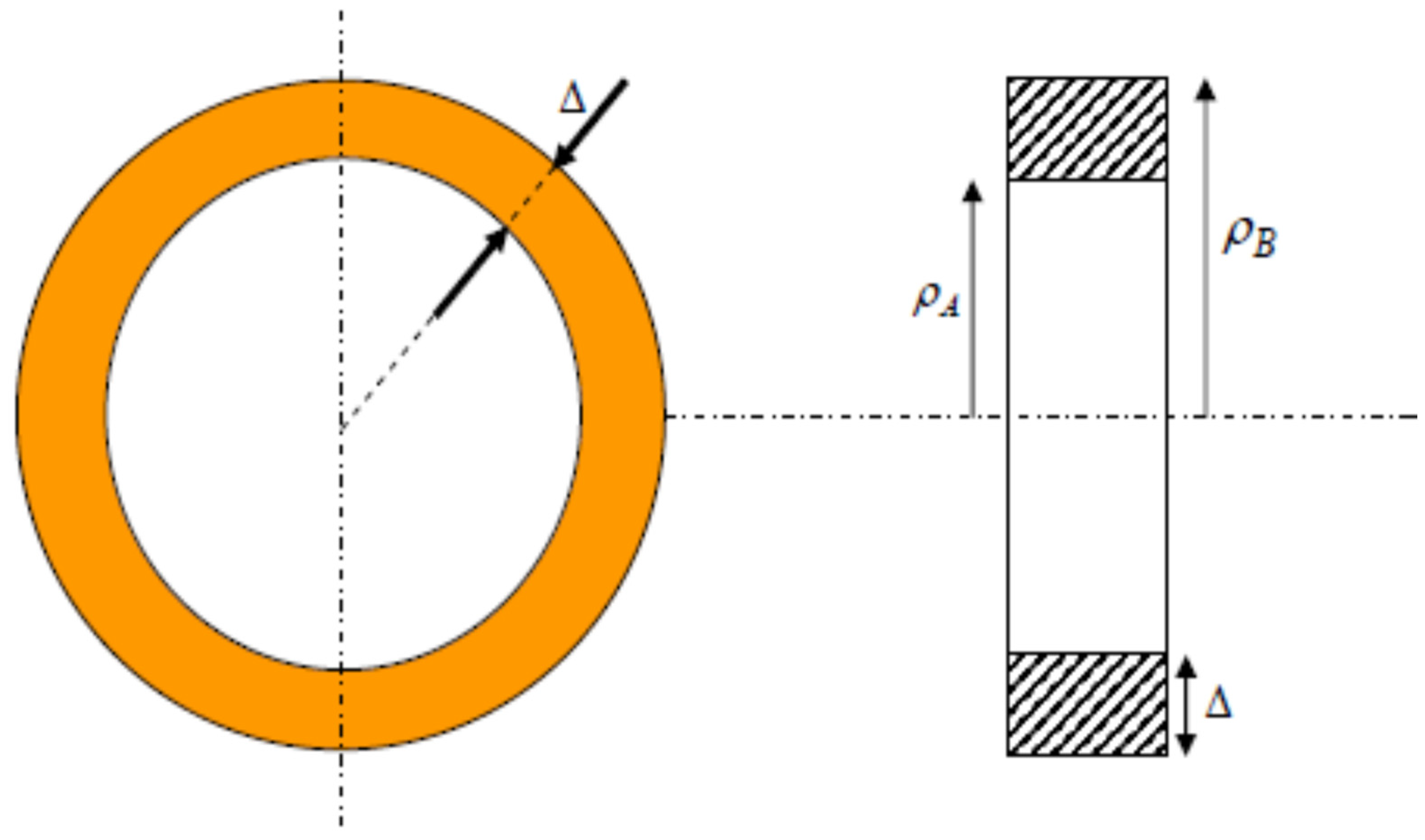
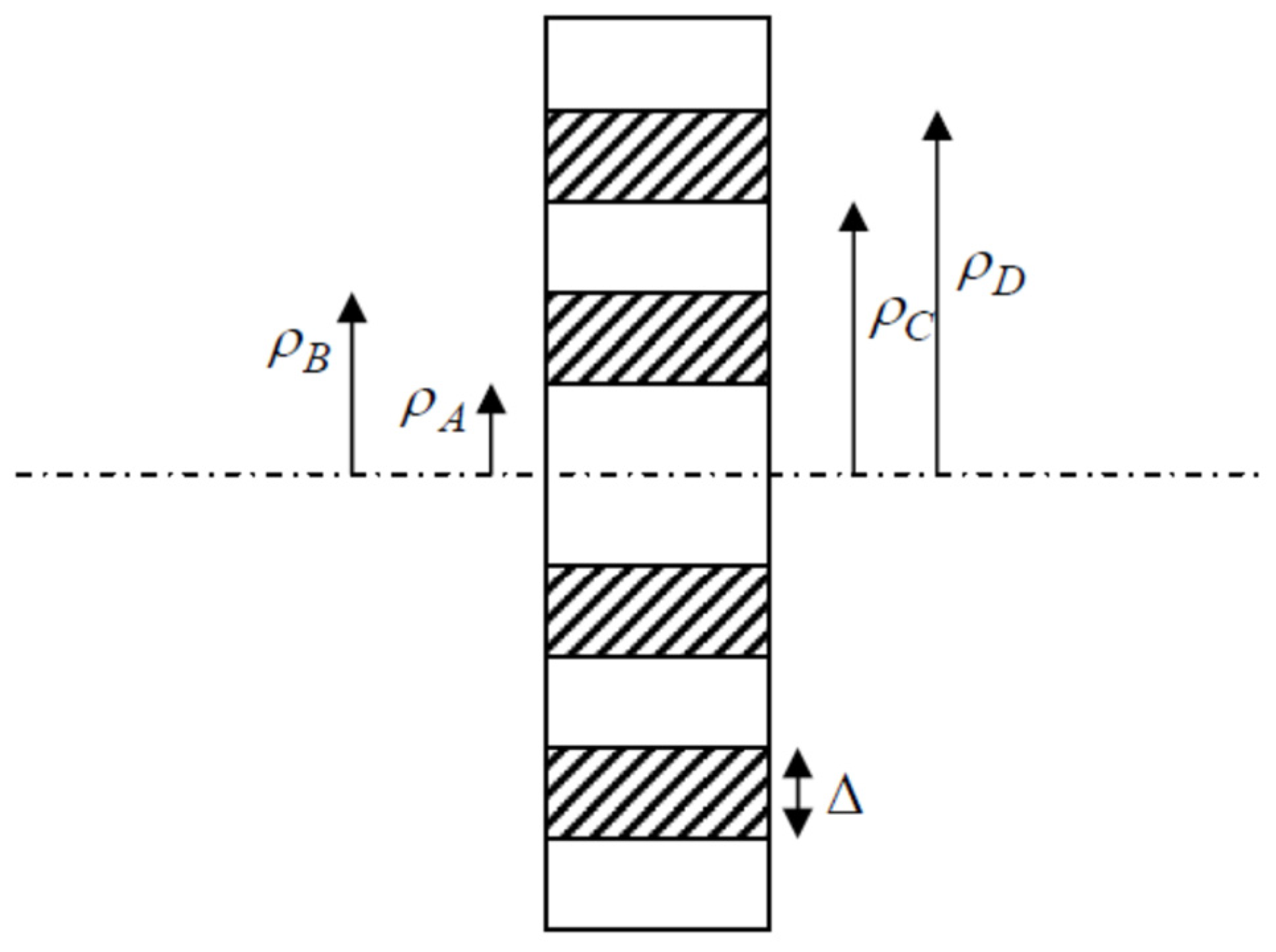
2.1. Absorbing Ring: Single-Pass Properties
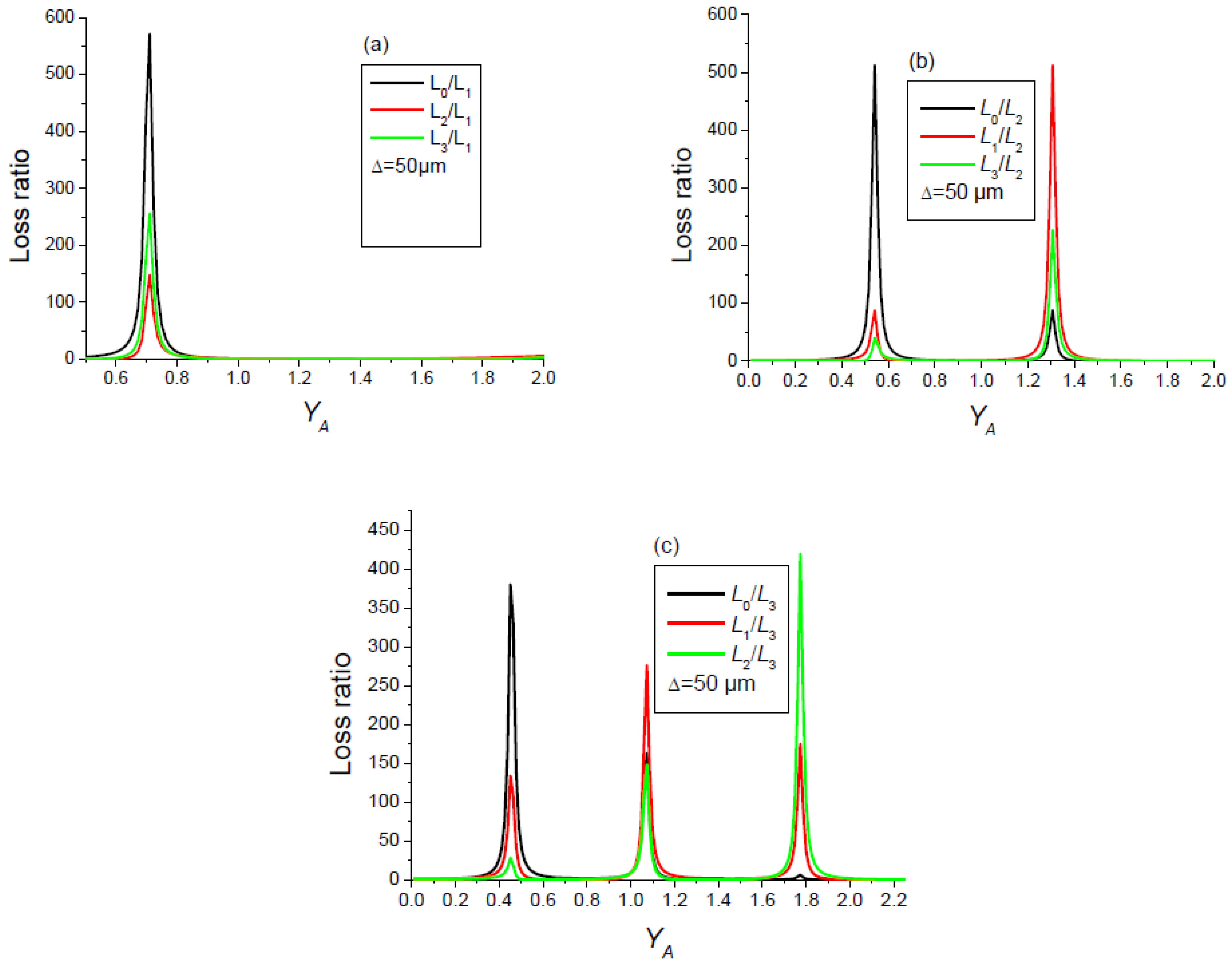
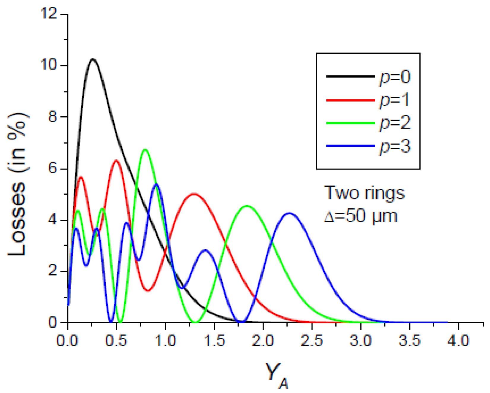
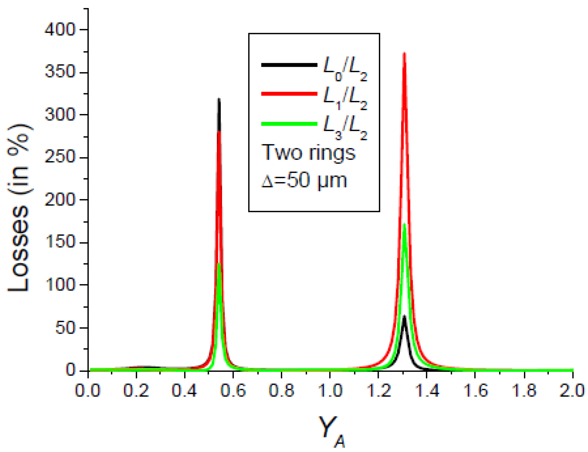
2.2. Multi-Pass Properties of Absorbing Rings
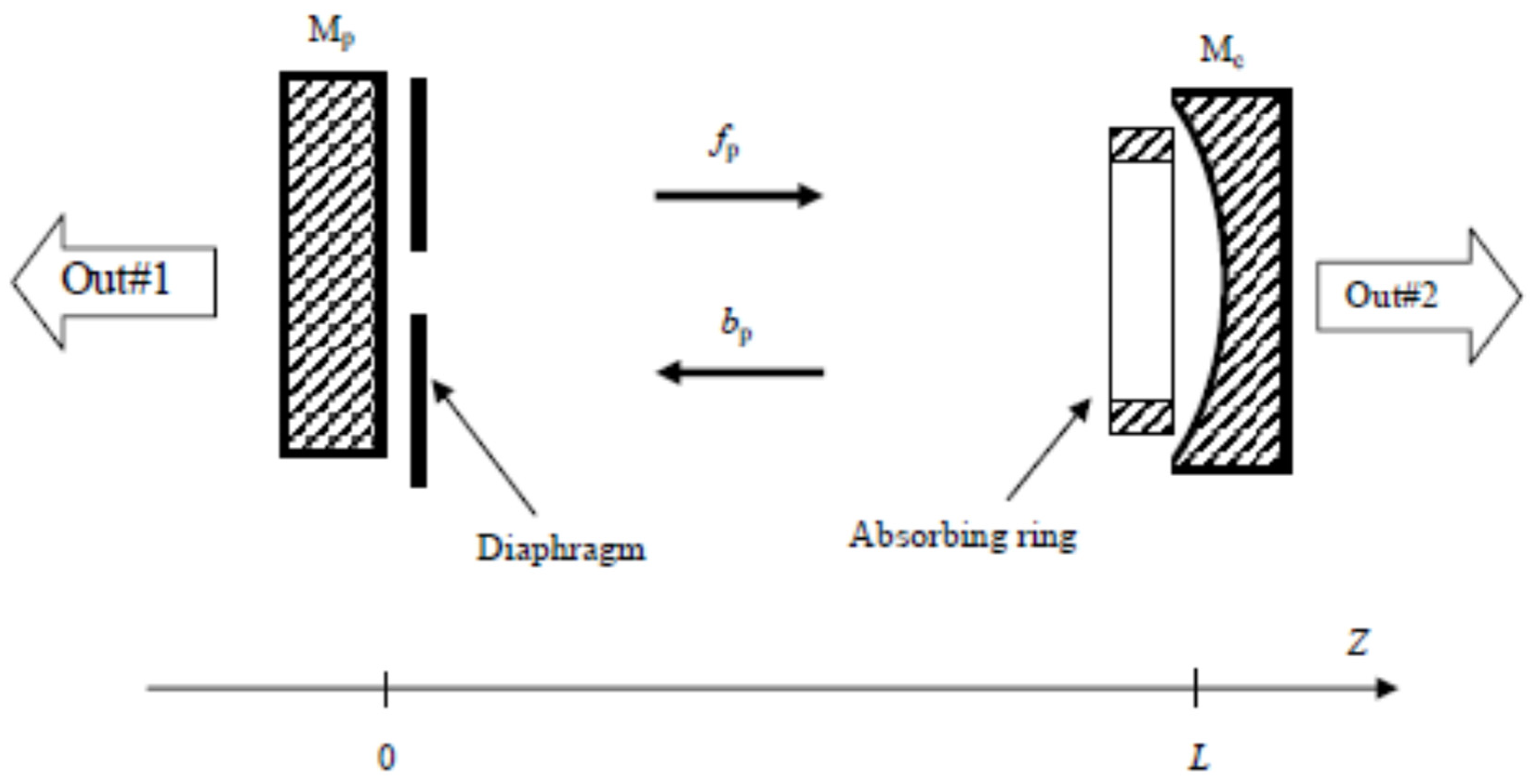
- The selection of a pure high-order transverse mode by an amplitude mask made up of p absorbing rings positioned on the nodes of the desired mode works well provided that the diaphragm is sufficiently open. Otherwise, the fundamental mode becomes the Gaussian mode with .
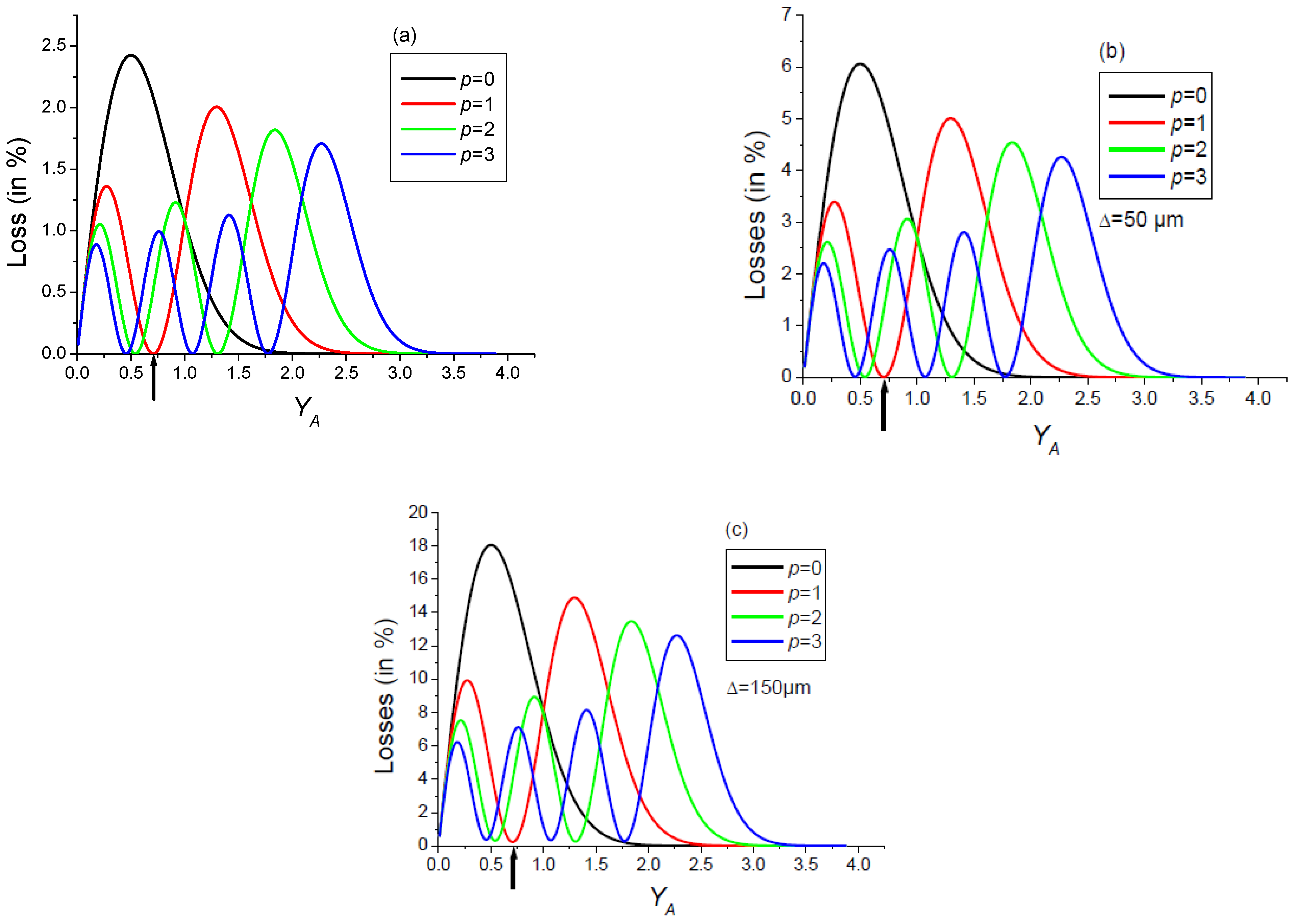
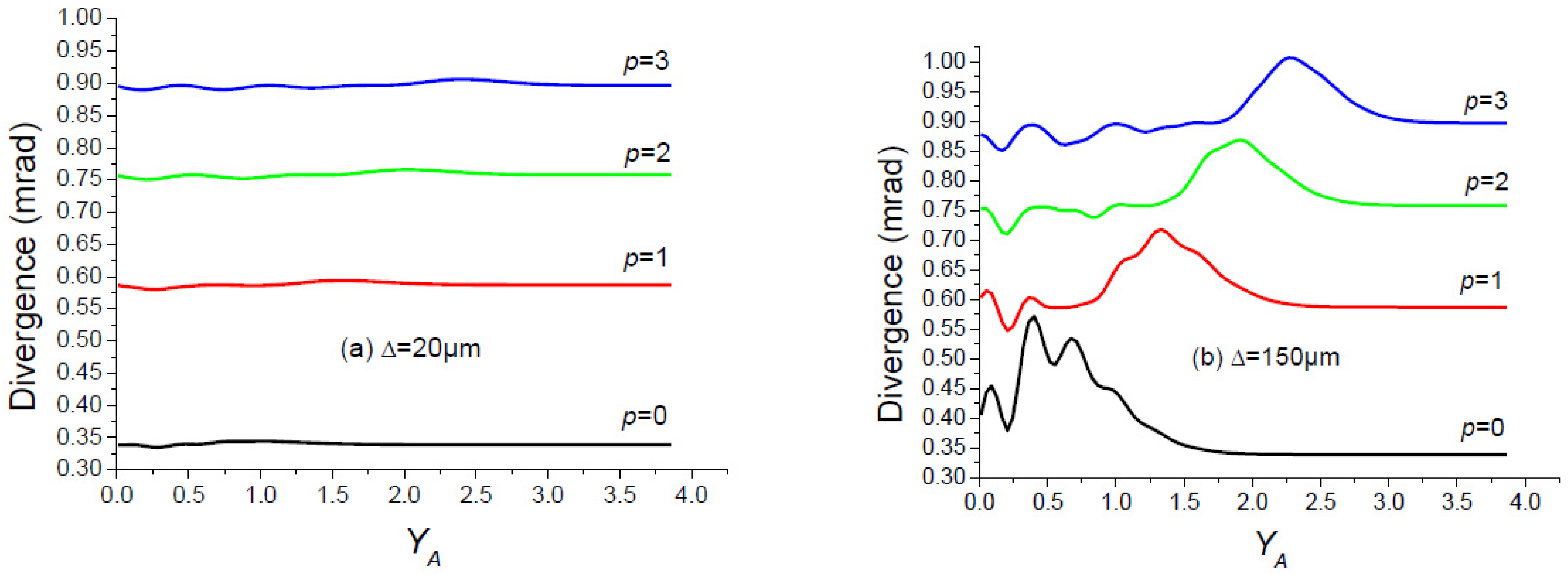
- The losses of the fundamental mode increase with the width Δ of the absorbing rings.
- The transverse mode discrimination of the cavity decreases with the increase in Δ.
3. Single-Pass and Multi-Pass Properties of a Binary Phase Mask
3.1. Single-Pass Properties of a Binary Phase Mask
3.2. Multi-Pass Properties of a Binary Phase Mask
4. Discussion
Author Contributions
Funding
Institutional Review Board Statement
Informed Consent Statement
Data Availability Statement
Conflicts of Interest
Appendix A

- (a)
- Cavity with a diaphragm and a binary phase mask (Figure A1):
- (b)
- Cavity with a diaphragm and an absorbing ring (Figure A2):
- (c)
- Output beam
References
- Fox, A.G.; Li, T. Resonant modes in a maser interferometer. Bell Syst. Tech. J. 1961, 40, 453–488. [Google Scholar] [CrossRef]
- Boyd, G.D.; Gordon, J.P. Confocal multimode resonator for millimetre through optical wavelength masers. Bell Syst. Tech. J. 1961, 40, 489–508. [Google Scholar] [CrossRef]
- Boyd, G.D.; Kogelnik, H. Generalized confocal resonator theory. Bell Syst. Tech. J. 1962, 41, 1347–1369. [Google Scholar] [CrossRef]
- Li, T. Diffraction loss and selection of modes in maser resonators with circular mirrors. Bell Syst. Tech. J. 1965, 44, 917–931. [Google Scholar] [CrossRef]
- Kogelnik, H.; Li, T. Laser beams and resonators. Appl. Opt. 1966, 5, 1550–1567. [Google Scholar] [CrossRef]
- Fox, A.G.; Li, T. Computation of resonator modes by the method of resonant excitation. IEEE J. Quantum Electron. 1968, 4, 460–465. [Google Scholar] [CrossRef]
- Valle, A. Selection and modulation of high-order transverse modes in vertical-cavity surface-emitting lasers. IEEE J. Quantum Electron. 1998, 34, 1924–1932. [Google Scholar] [CrossRef]
- Quirce, A.; Valle, A.; Hurtado, A.; Gimenez, C.; Pesquera, L.; Adams, M.J. Experimental study of transverse mode selection in VCSELs induced by parallel polarised optical injection. IEEE J. Quantum Electron. 2010, 46, 467–473. [Google Scholar] [CrossRef]
- Kim, K.; Bittner, S.; Zeng, Y.; Guazzotti, S.; Hess, O.; Wang, Q.J.; Cao, H. Massively parallel ultrafast random bit generation with a chip-scale laser. Sciences 2021, 371, 948. [Google Scholar] [CrossRef]
- Kim, K.; Bittner, S.; Zeng, Y.; Guazzotti, S.; Hess, O.; Wang, Q.J.; Cao, H. Sensitive control of broad-area semiconductor lasers by cavity shape. APL Photonics 2022, 7, 056106. [Google Scholar] [CrossRef]
- Ledentsov, N.N.; Makarov, Y.; Shchukin, V.A.; Kalosha, V.P.; Leventsov Jr, N.; Chrochos, L.; Bou Sanayeh, M.; Turkiewicz, J.P. High speed VCEL Technology and applications. J. Light Technol. 2022, 40, 1749–1763. [Google Scholar] [CrossRef]
- Koechner, W. Solid-State Laser Engineering, 6th ed.; Springer Sciences: Berlin/Heidelberg, Germany, 2006. [Google Scholar]
- Saleh, B.E.A.; Teich, M.C. Fundamentals of Photonics, 2nd ed.; Wiley-Interscience: Hoboken, NJ, USA, 2007. [Google Scholar]
- Hodgson, N.; Weber, H. Laser Resonators and Beam Propagation, 2nd ed.; Springer Sciences: Berlin/Heidelberg, Germany, 2005. [Google Scholar]
- Arfken, G. Mathematical Methods for Physicists, 2nd ed.; Academic Press: Cambridge, MA, USA, 1973. [Google Scholar]
- Menzel, R. Photonics; Springer: Cham, Switzerland, 2001; Chapter 2. [Google Scholar]
- Aït-Ameur, K. Amplitude and phase clipping: Strehl ratio versus divergence. Opt. Commun. 2012, 285, 699–705. [Google Scholar] [CrossRef]
- Siegman, A.E. New developments in laser resonators. Proc. SPIE 1990, 1224, 2–14. [Google Scholar]
- Johnston, T.F. M2 concept characterizes beam quality. Laser Focus World 1990, 26, 173–174. [Google Scholar]
- Siegman, A.E. Defining, measuring, and optimizing laser beam quality. Opt. Reson. Coherent Opt. 1993, 1868, 2–14. [Google Scholar]
- Ait-Ameur, K. The Advantages and Disadvantages of Using Structured High-Order but Single Laguerre–Gauss LGp0 Laser Beams. Photonics 2024, 11, 217. [Google Scholar] [CrossRef]
- Chelkowski, S.; Hild, S.; Freise, A. Prospects of higher-order Laguerre-Gauss modes in future gravitational wave detectors. Phys. Rev. D 2009, 79, 122002. [Google Scholar] [CrossRef]
- Granata, M.; Buy, C.; Ward, R.; Barsuglia, M. Higher-order Laguerre-Gauss mode generation and interferometry for gravitational wave detectors. Phys. Rev. Lett. 2010, 105, 231102. [Google Scholar] [CrossRef]
- Sorazu, B.; Fulda, P.J.; Barr, B.W.; Bell, A.S.; Bond, C.; Carbone, L.; Freise, A.; Hild, S.; Huttner, S.H.; Macarthur, J.; et al. Experimental test of higher-order Laguerre-Gauss modes in the 10 m Glasgow prototype interferometer. Class. Quantum Grav. 2013, 30, 035004. [Google Scholar] [CrossRef]
- Alloca, A.; Gatto, A.; Tacca, M.; Day, R.A.; Barsuglia, M.; Pillant, G.; Buy, C.; Vajente, G. Higher-order Laguerre-Gauss interferometry for gravitational wave detectors with in situ mirror defects compensation. Phys. Rev. D 2015, 92, 102002. [Google Scholar] [CrossRef]
- Noack, A.; Boyan, C.; Willke, B. Higher-order Laguerre-Gauss modes in (non-) planar four-mirror cavities for future gravitational wave detectors. Opt. Lett. 2017, 42, 751–754. [Google Scholar] [CrossRef] [PubMed]
- Ngcobo, S.; Aït-Ameur, K.; Passilly, N.; Hasnaoui, A.; Forbes, A. Exciting higher-order radial Laguerre-Gaussian modes in a diode-pumped solid-state laser resonator. Appl. Opt. 2013, 52, 2093–2101. [Google Scholar] [CrossRef] [PubMed]
- Abramski, K.M.; Baker, H.J.; Colley, A.D.; Hall, D.R. Single mode selection using coherent imaging within a slab waveguide CO2 laser. Appl. Phys. Lett. 1992, 60, 2469–2471. [Google Scholar] [CrossRef]
- Chu, S.C.; Chen, Y.T.; Tsai, K.F.; Otsuka, K. Generation of high-order Hermite-Gaussian modes in end-pumped solid-state lasers for square vortex array laser beam generation. Opt. Express 2012, 20, 7128–7141. [Google Scholar] [CrossRef]
- Smith, P.W. Mode selection in Lasers. Proc. IEEE 1965, 60, 422–440. [Google Scholar] [CrossRef]
- Gordon, J.P.; Kogelnik, H. Equivalence relations among spherical mirror optical resonators. Bell Syst. Tech. J. 1964, 43, 2873–2886. [Google Scholar] [CrossRef]
- Li, T. Mode selection in an aperture-limited concentric maser interferometer. Bell Syst. Tech. J. 1963, 42, 2609–2620. [Google Scholar] [CrossRef]
- Kortz, H.P.; Weber, H. Diffraction losses and mode structure of equivalent TEM00 optical resonators. Appl. Opt. 1981, 20, 1936–1940. [Google Scholar] [CrossRef]
- Cagniot, E.; Derrar-Kaddour, Z.; Fromager, M.; Aït-Ameur, K. Improving both transverse mode discrimination and diffraction losses in a plano-concave cavity. Opt. Commun. 2008, 281, 4449–4454. [Google Scholar] [CrossRef]
- Naidoo, D.; Ait-Ameur, K.; Litvin, I.; Fromager, M.; Forbes, A. Observing mode propagation inside a laser cavity. New J. Phys. 2012, 14, 053021. [Google Scholar] [CrossRef]
- Oron, R.; Danziger, Y.; Davidson, N.; Friesem, A.A.; Hasman, E. Discontinuous phase elements for transverse mode selection in laser resonators. Appl. Phys. Lett. 1999, 74, 1373–1375. [Google Scholar] [CrossRef]
- Ishaaya, A.A.; Davidson, N.; Machavariani, G.; Hasman, E.; Friesem, A.A. Efficient selection of High-order Laguerre-Gaussian modes in a Q-switched Nd:YAG laser. IEEE J. Quantum Electron. 2003, 9, 74–82. [Google Scholar] [CrossRef]
- Ishaaya, A.A.; Davidson, N.; Machavariani, G.; Hasman, E.; Friesem, A.A. Very high-order pure Laguerre-Gaussian mode selection in a passive Q-switched Nd:YAG laser. Opt. Express 2005, 13, 4952–4962. [Google Scholar] [CrossRef] [PubMed]
- Senatsky, Y.; Bisson, J.F.; Shelobolin, A.; Shirakawa, A.; Ueda, K. Circular modes selection in Yb:YAG laser using an intracavity lens with spherical aberration. Laser Phys. 2009, 19, 911–918. [Google Scholar] [CrossRef]
- Thirugnansambandam, M.P.; Senatsky, Y.; Ueda, K. Generation of very-high order Laguerre-Gaussian modes in Yb:YAG ceramic laser. Laser Phys. Lett. 2010, 7, 637–643. [Google Scholar] [CrossRef]
- Senatsky, Y.; Bisson, J.F.; Shirakawa, A.; Thirugnansambandam, M. Laguerre-Gaussian modes selection in diode-pumped solid-state lasers. Opt. Rev. 2012, 19, 201–222. [Google Scholar] [CrossRef]
- Sheng, Q.; Wang, A.; Ma, Y.; Wang, S.; Wang, M.; Shi, Z.; Liu, J.; Fu, S.; Shi, W.; Yao, J.; et al. Intracavity spherical aberration for selective generation of single-transverse-mode Laguerre-Gaussian output with order up to 95. PhotoniX 2022, 3, 4. [Google Scholar] [CrossRef]
- Hall, D.R.; Jackson, P.E. The Physics and Technology of Laser Resonators; Institute of Physics Publishing: Bristol, UK, 1992; Chapter 9. [Google Scholar]
- Ait-Ameur, K. Influence of the longitudinal position of an aperture inside a cavity on the transverse mode discrimination. Appl. Opt. 1993, 32, 7366–7372. [Google Scholar] [CrossRef]
- Mudge, D.; Ostermeyer, M.; Veitch, P.J.; Munch, J.; Middlemiss, B.; Ottaway, D.J.; Hamilton, M.W. Power scalable TEM00 CW Nd:YAG laser with thermal lens compensation. IEEE J. Sel. Top. Quantum Electron. 2000, 6, 643–649. [Google Scholar] [CrossRef]
- Graf, T.; Wyss, E.; Roth, M.; Weber, H.P. Laser resonator with balanced thermal lenses. Opt. Commun. 2000, 190, 327–331. [Google Scholar] [CrossRef]
- Wyss, E.; Roth, M.; Graf, T.; Weber, H.P. Thermooptical compensation methods for high-power lasers. IEEE J. Quantum Electron. 2002, 38, 1620–1628. [Google Scholar] [CrossRef]
- Chen, H.; Liu, Q.; Yan, X.; Gong, M. High power Q-switched TEM00 Nd:YVO4 laser self-adaptive compensation of thermal lensing effect. Las. Phys. 2010, 20, 1594–1597. [Google Scholar] [CrossRef]
- Wang, J.; Cheng, T.; Wang, L.; Yang, J.; Sun, D.; Yin, S.; Wu, X.; Jiang, H. Compensation of strong thermal lensing in an LD side-pumped high-power Er: YSGG laser. Las. Phys. 2015, 12, 105004. [Google Scholar] [CrossRef]
- Shang, P.; Bai, L.; Wang, S.; Cai, D.; Li, B. Research progress on thermal effect of LD pumped solide state laser. Opt. Las. Eng. 2023, 157, 108640. [Google Scholar]
- Veldkamp, W.B.; McHugh, T.J. Binary optics. Sci. Am. 1992, 266, 92–97. [Google Scholar] [CrossRef]
- O’Shea, D.C.; Beletic, J.W.; Poutous, M. Binary-mask generation for diffractive optical elements using microcomputers. Appl. Opt. 1993, 32, 2566–2572. [Google Scholar] [CrossRef]
- Cordingley, J. Application of a binary diffractive optics for beam shaping in semiconductor processing by lasers. Appl. Opt. 1993, 32, 2538–2542. [Google Scholar] [CrossRef]
- Skeren, M.; Ritcher, I.; Fiala, P. Design of binary phase-only diffractive optical elements for laser beam shaping. Proc. SPIE Laser Beam Shap. 2000, 4095, 154–164. [Google Scholar]
- Raciukaitis, G.; Stankevicius, E.; Geys, P.; Gedvilas, M.; Bischoff, C.; Jäger, E.; Umhofer, U.; Völklein, F. Laser processing by using diffractive optical laser beam shaping technique. J. Laser Micro/Nanoeng. 2011, 6, 37–43. [Google Scholar] [CrossRef]
- Siemon, A.; Siemon, A.; Suszek, J.; Kowalczyk, A.; Bomba, J.; Sobczyk, A. THz beam shaping based on paper diffractive optics. IEEE Trans. Terahertz Sci. Technol. 2016, 6, 568–575. [Google Scholar] [CrossRef]
- Barlev, O.; Golub, M.A. Multifonctional binary diffractive optical elements for structured light projectors. Opt. Express 2018, 26, 21092–21107. [Google Scholar] [CrossRef] [PubMed]
- Marchesini, S.; Sakdinawat, A. Shaping coherent x-rays with binary optics. Opt. Express 2019, 27, 907–917. [Google Scholar] [CrossRef] [PubMed]
- Cagniot, E.; Fromager, M.; Godin, T.; Passilly, N.; Brunel, M.; Ait-Ameur, K. Variant of the method of Fox and Li dedicated to intracavity laser beam shaping. J. Opt. Soc. Am. A 2011, 28, 489–495. [Google Scholar] [CrossRef]
- Siegman, A.E. Binary phase plates cannot improve laser beam quality. Opt. Lett. 1993, 18, 675–677. [Google Scholar] [CrossRef]
- Hasnaoui, A.; Bencheikh, A.; Aït-Ameur, K. Tailored TEMp0 beams for large size 3-D laser prototyping. Opt. Las. Eng. 2011, 49, 248–251. [Google Scholar] [CrossRef]
- Haddadi, S.; Ait-Ameur, K. Improvement of optical trapping effect by structuring the illuminating laser beam. Optik 2022, 251, 168439. [Google Scholar] [CrossRef]
- Smith, P.W. Stabilised single-frequency output from a long laser cavity. IEEE J. Quantum Electron 1965, 1, 343–348. [Google Scholar] [CrossRef]
- Habchi, A.; Harfouche, A.; Aït-Ameur, K. Flexible control of laser transverse modes using a Fox-Smith mirror. Appl. Phys. B 2021, 127, 97. [Google Scholar] [CrossRef]
- Stéphan, G.; Trümper, M. Inhomogeneity effects in a gas laser. Phys. Rev. A. 1983, 28, 2344–2362. [Google Scholar] [CrossRef]
- Ait-Ameur, K.; Ladjouze, H. Fundamental mode distribution in a diaphragmed cavity. J. Phys. D Appl. Phys. 1988, 21, 1566–1577. [Google Scholar] [CrossRef]
- De Saint Denis, R.; Passilly, N.; Aït-Ameur, K. Laser beam brightness of apertured resonators. Opt. Commun. 2006, 264, 193–202. [Google Scholar] [CrossRef]
- Vicalvi, S.; Borghi, R.; Santarsiero, M.; Gori, F. Shape-invariance error for axially symmetric light beams. J. Quantum Electron. 1998, 34, 2109–2116. [Google Scholar] [CrossRef]


| p | |||
|---|---|---|---|
| 1 | 0.707106 | ||
| 2 | 0.541195 | 1.306562 | |
| 3 | 0.455946 | 1.071046 | 1.773407 |
| Zero# | 1 | 2 | 3 |
|---|---|---|---|
| (L1)min in % | 0.002 | ||
| (L2)min in % | 7.5 × 10⁻⁴ | 6.2 × 10⁻⁴ | |
| (L3)min in % | 0.0016 | 9.4 × 10⁻⁴ | 6.7 × 10⁻⁴ |
| L (mm) | g | YR | Yc | LFM in % | Fc | M2 | Figure 10 |
|---|---|---|---|---|---|---|---|
| 93 | 0.38 | 0.707 | 3.9 | 0.25 | 5.9 | 3.005 | a |
| 124 | 0.17 | 0.54 | 4.1 | 0.2 | 10 | 5 | b |
| 137 | 0.08 | 0.45 | 3.4 | 0.2 | 3 | 7.008 | c |
| p | Radius of the Rings in µm | ||
|---|---|---|---|
| 1 | 131 | ||
| 2 | 100 | 243 | |
| 3 | 85 | 199 | 330 |
| Δ (µm) | Yc | (mm) | M² | LFM | Fc |
|---|---|---|---|---|---|
| 10 | 1.65 | 0.84 | 1.08 | 11.5% | 1.63 |
| 10 | 2.5 | 1.3 | 3.018 | 0.25% | 53 |
| 15 | 1.65 | 0.84 | 1.09 | 16.25% | 1.42 |
| 15 | 2.5 | 1.3 | 3.02 | 0.4% | 23.6 |
| 20 | 1.65 | 0.84 | 1.07 | 20.7% | 1.34 |
| 20 | 2.5 | 1.3 | 3.008 | 0.87% | 11.35 |
| 25 | 1.65 | 0.84 | 1.1 | 25% | 1.14 |
| 25 | 2.5 | 1.3 | 3.008 | 1.7% | 9.4 |
| Δ (µm) | Yc | (mm) | M² | LFM | Fc |
|---|---|---|---|---|---|
| 10 | 2 | 1.02 | 1.03 | 14.5% | 1.9 |
| 10 | 3 | 1.53 | 5 | 0.3% | 28.4 |
| 15 | 2 | 1.02 | 1.03 | 20.5% | 1.15 |
| 15 | 3 | 1.53 | 5 | 0.8% | 19 |
| 20 | 2 | 1.02 | 1.012 | 26.2% | 1.05 |
| 20 | 3 | 1.53 | 5.01 | 1.9% | 9.2 |
| 25 | 2 | 1.03 | 1.03 | 31.7% | 1.15 |
| 25 | 3 | 1.53 | 5 | 3.4% | 1.28 |
| Δ (µm) | Yc | (mm) | M² | LFM | Fc |
|---|---|---|---|---|---|
| 10 | 2 | 1.02 | 1.016 | 17% | 1.23 |
| 10 | 3.5 | 1.78 | 7 | 0.4% | 23.6 |
| 15 | 2 | 1.02 | 1.016 | 24% | 1.12 |
| 15 | 3.5 | 1.78 | 7 | 1.5% | 10 |
| 20 | 2 | 1.02 | 1.016 | 31% | 1.08 |
| 20 | 3.5 | 1.78 | 7 | 3.2% | 5.6 |
| 25 | 2 | 1.02 | 1.016 | 37.5% | 1.05 |
| 25 | 3.5 | 1.78 | 7 | 5.7% | 1.08 |
| YPI | θ0 (rad) | θ1 (rad) | θ2 (rad) | θ3 (rad) |
|---|---|---|---|---|
| 0.707 | 22.6 × 10⁻⁴ | 6.1 × 10⁻⁴ | 12.4 × 10⁻⁴ | 16.4 × 10⁻⁴ |
| 0.541 | 23.5 × 10⁻⁴ | 10.9 × 10⁻⁴ | 7.5 × 10⁻⁴ | 11 × 10−4 |
| 0.455 | 23 × 10−4 | 14.6 × 10⁻⁴ | 10 × 10−4 | 8.9 × 10⁻⁴ |
| YPI | Loss for p = 0 | Loss for p = 1 | Loss for p = 2 | Loss for p = 3 | Fc |
|---|---|---|---|---|---|
| 0.707 | 7.7% | 0.19% | 2.13% | 3.95% | 11.2 |
| 0.541 | 9.38% | 1.64% | 0.26% | 1.2% | 4.6 |
| 0.455 | 8.9% | 3.33% | 0.95% | 0.35% | 2.7 |
| BAPP | Loss for p = 0 | Loss for p = 1 | Loss for p = 2 | Loss for p = 3 | Fc |
|---|---|---|---|---|---|
| #1 | 7.7% | 0.19% | 2.13% | 3.95% | 11.2 |
| #2 | 10.67% | 10.74% | 0.48% | 4.92% | 10.25 |
| #3 | 15.2% | 10.98% | 11% | 0.65% | 16.9 |
| L (mm) | g | YPI | Yc | LFM in % | FC | M2 |
|---|---|---|---|---|---|---|
| 93 | 0.38 | 0.707 | 3.1 | 3 | 2.84 | 2.97 |
| 124 | 0.17 | 0.54 | 4.5 | 1.7 | 1.85 | 5.15 |
| 137 | 0.08 | 0.45 | 5 | 2.3 | 1.19 | 7.008 |
| Yc | LFM | Fc | M2 | |
|---|---|---|---|---|
| BAPP#1 | 6.5 | 0.30% | 2.49 | 3 |
| BAPP#2 | 6.5 | 0.74% | 2.88 | 4.98 |
| BAPP#3 | 6.5 | 1.28% | 1.59 | 6.97 |
Disclaimer/Publisher’s Note: The statements, opinions and data contained in all publications are solely those of the individual author(s) and contributor(s) and not of MDPI and/or the editor(s). MDPI and/or the editor(s) disclaim responsibility for any injury to people or property resulting from any ideas, methods, instructions or products referred to in the content. |
© 2025 by the authors. Licensee MDPI, Basel, Switzerland. This article is an open access article distributed under the terms and conditions of the Creative Commons Attribution (CC BY) license (https://creativecommons.org/licenses/by/4.0/).
Share and Cite
Aït-Ameur, K.; Fromager, M.; Hasnaoui, A. Numerical Simulation of an Optical Resonator for the Generation of Radial Laguerre–Gauss LGp0 Modes. Appl. Sci. 2025, 15, 3331. https://doi.org/10.3390/app15063331
Aït-Ameur K, Fromager M, Hasnaoui A. Numerical Simulation of an Optical Resonator for the Generation of Radial Laguerre–Gauss LGp0 Modes. Applied Sciences. 2025; 15(6):3331. https://doi.org/10.3390/app15063331
Chicago/Turabian StyleAït-Ameur, Kamel, Michael Fromager, and Abdelkrim Hasnaoui. 2025. "Numerical Simulation of an Optical Resonator for the Generation of Radial Laguerre–Gauss LGp0 Modes" Applied Sciences 15, no. 6: 3331. https://doi.org/10.3390/app15063331
APA StyleAït-Ameur, K., Fromager, M., & Hasnaoui, A. (2025). Numerical Simulation of an Optical Resonator for the Generation of Radial Laguerre–Gauss LGp0 Modes. Applied Sciences, 15(6), 3331. https://doi.org/10.3390/app15063331