
The Additive Manufacturing of Glass: A Critical Review

 , , ,
, , ,
Abstract
1. Introduction
1.1. Glass and Its Relevance
1.2. Glass as a Processable Material
1.3. General AM Overview and Examples
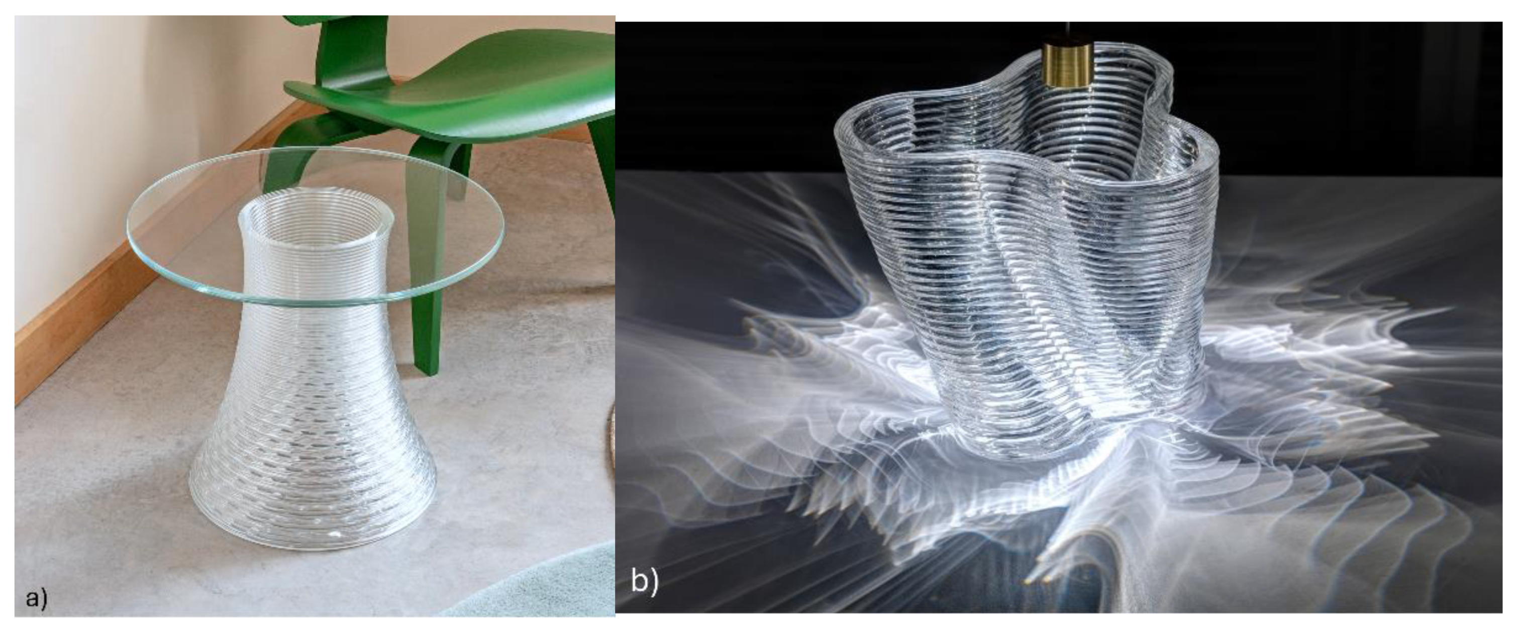
1.3.1. Relevance to Art and Design
- Rapid prototyping, allowing the translation of an idea into a form within a short period of time (i.e., hours);
- The ability to realise shapes and structures, from direct manufacturing in 3D, that are otherwise unobtainable from conventional glass processing methods;
- The ability to realise detail in ‘internal’ structures that is not possible through methods analogous to the lost-wax approach;
- The ready combination of colour transitions, and diverse features.
1.3.2. Relevance to Architecture
2. Glass AM Techniques
2.1. Direct Methods
2.1.1. Directed Energy Deposition (DED)
2.1.2. Selective Laser Melting
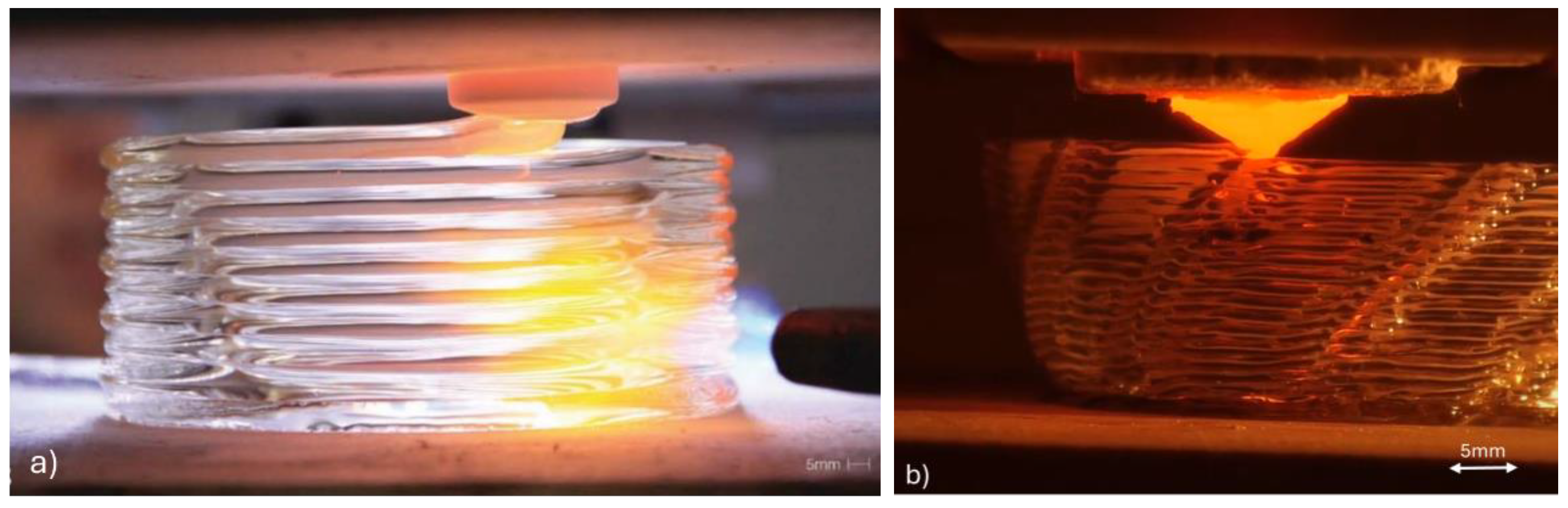
2.1.3. Semi-Solid Processing
2.1.4. Low-Temperature Semi-Solid Processing
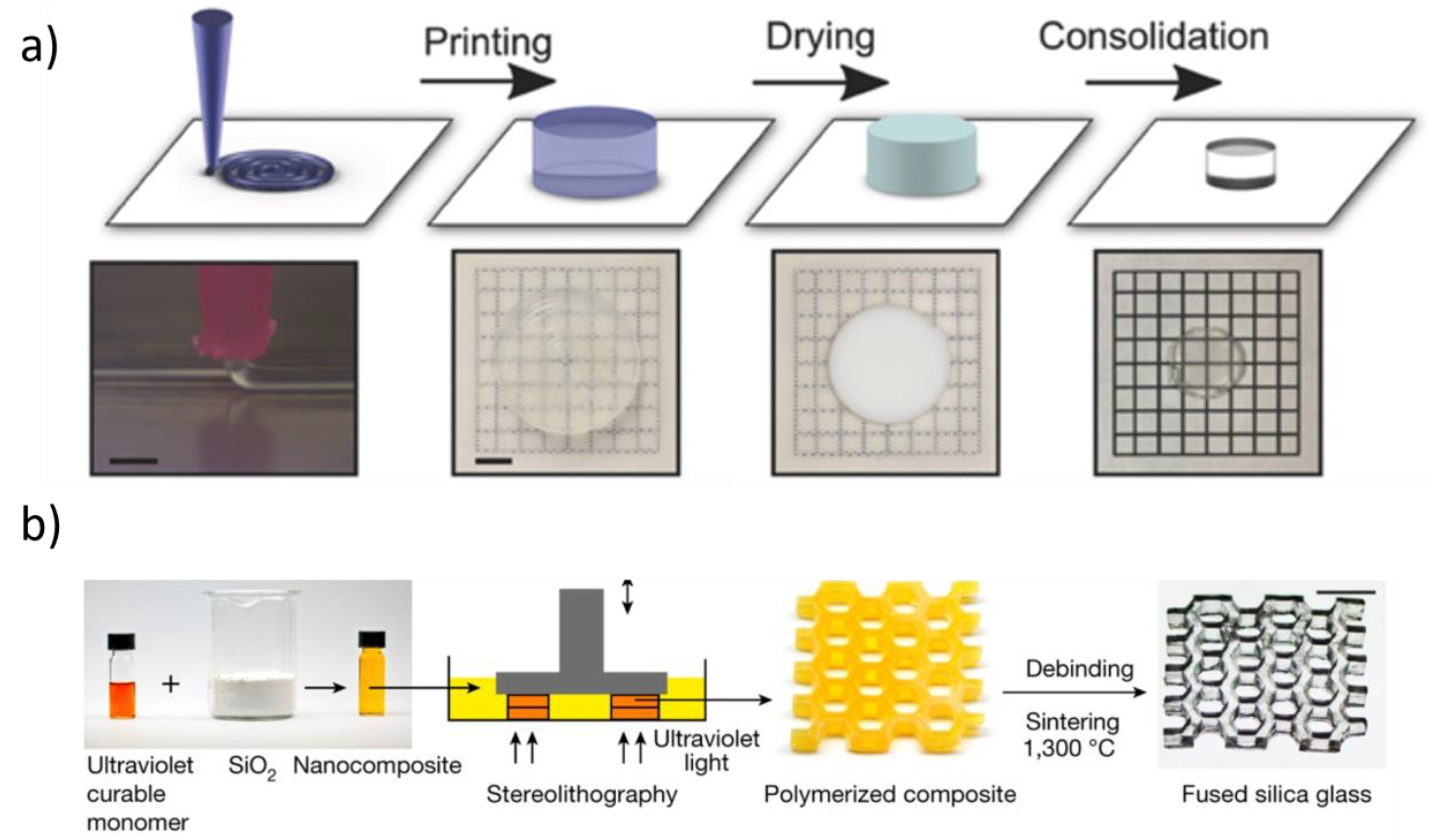
2.2. Binder-Based Additive Manufacturing
2.3. Synopsis of Reported Glass AM Methods

| Method | Feed Material | Deposition Width Scale (mm) | Length Scale (mm) | Advantages | Limitations | Related Literature |
|---|---|---|---|---|---|---|
| Directed Energy Deposition | Fused Quartz Filament | ~0.1–4 | ~1–200 |
|
| [28,31,32,34,36,37,38,40,58,59] |
| Soda–Lime Filament/Powder | [14,22,26,27,29,30,33,39] | |||||
| Borosilicate Filament | [12,13,14,27,35] | |||||
| Germanate Filament | [60] | |||||
| Selective Laser Melting | Fused Quartz Powder | ~0.1–1 | ~1–100 |
|
| [61] |
| Soda–Lime Powder | [22,42,43,44,45,61,62] | |||||
| Borosilicate Powder | [44,46,63] | |||||
| Fused Deposition Modelling | Soda–Lime Filament/Cullet | ~0.1–20 | ~1–~300 |
|
| [10,15,64] |
| Low-Temp Glass Filament/Pellets | ~0.4 (Polymer printing) | ~1–200 (Polymer printing) |
|
| [49,50,65,66,67,68] | |
| Binder-Based | Various (See Table 2) |
|
| (See Table 2) | ||
| Binder-Based AM Method | Feedstock Material | Deposition Width Scale (mm) | Length Scale (mm) | Related Literature |
|---|---|---|---|---|
| Fused Deposition Modelling | Silica particles + Thermoplastic polymer binder | ~0.4 (Polymer printing) | ~1–200 (Polymer printing) | [53] |
| Direct Ink Writing | Colloid of silica-based glass feedstock, rheological agents + Solvent | ~0.1–1 | ~1–200 | [51,54,57,69,70,71] |
| Light-Based (Stereolithography, Two-Photon Polymerisation, Direct Laser Writing, etc.) | Silica particles + Photopolymer binder | ~0.0001–0.1 | ~1–200 | [52,55,56,72,73,74,75,76,77,78,79,80,81,82,83,84] |
| Patent Name | Date First Filed | Assignee | Patent Number | Ref. |
|---|---|---|---|---|
| Methods and apparatus for additive manufacturing of glass | 2015 | Massachusetts Institute of Technology | US10266442B2 | [85] |
| A kind of 3D printing equipment for chalcogenide glass element | 2016 | China Building Materials Academy | CN106116120A | [86] |
| Additive manufacturing systems and method for making glass articles | 2017 | Corning Incorporated | US20210101818A1 | [87] |
| 3D printing system for printing high melting temperature materials | 2018 | Micron 3Dp Ltd., D Swarovski KG (Location depending) | WO2018163006A1 | [88] |
| Three-dimensional printing system | 2020 | Maple Glass Printing Pty. Ltd. | AU2021289614A1 | [89] |
3. A Focus on Semi-Solid Processing for Glass AM
3.1. Process Overview
3.2. Low-Viscosity Glass Feedstock Methods
3.3. High-Viscosity Glass Feedstock Methods
3.3.1. Sustainability in Glass AM Through EAM and Example Models
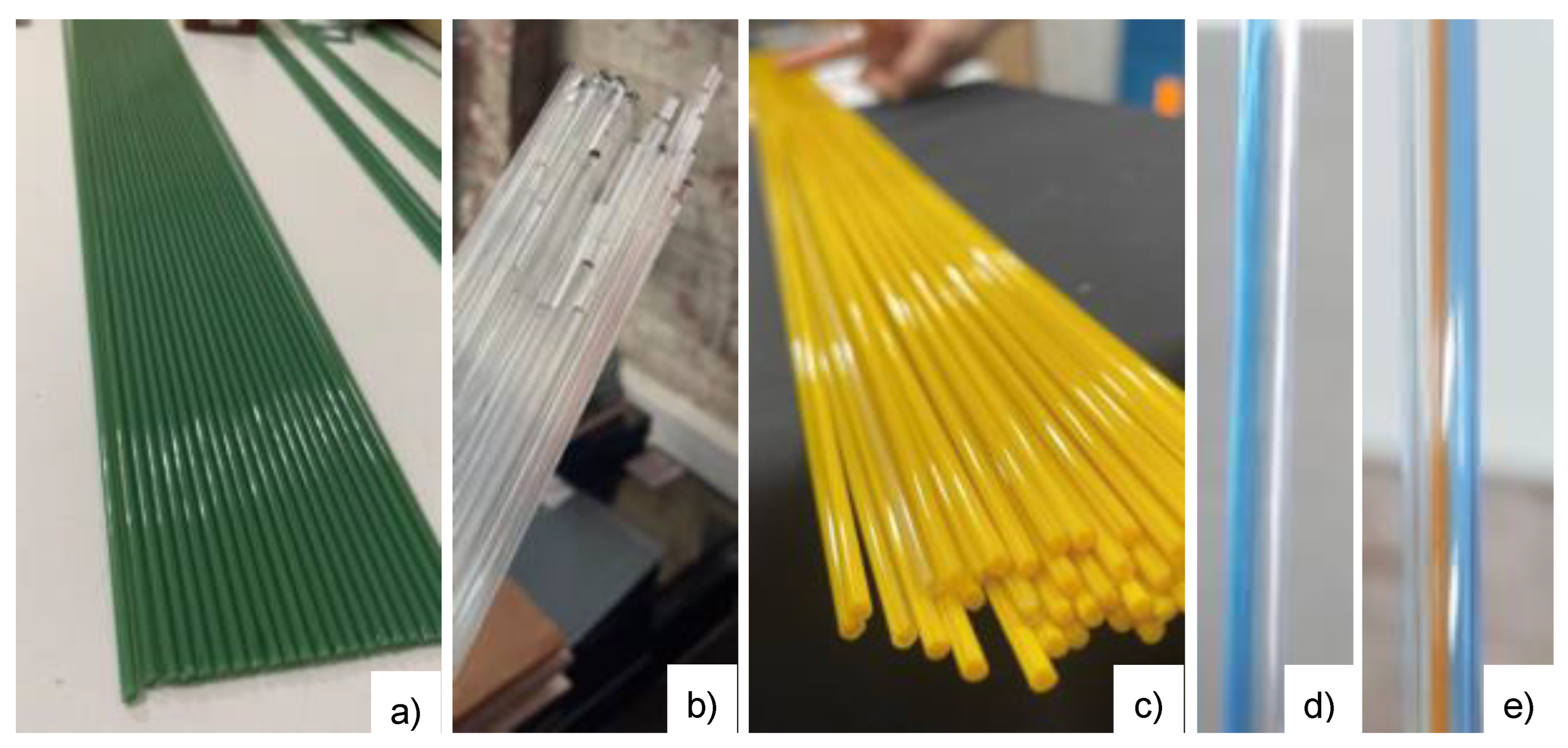
3.3.2. The Production of Glass Filament
3.4. Postprocessing of AM Glass
4. Properties of AM Glass
4.1. Mechanical Properties
| AM Process | Glass Material | Loading Scenario | Sample Dimensions | Failure Stress (N/mm2) | Image | Ref. |
|---|---|---|---|---|---|---|
| Low-viscosity glass AM | Soda–Lime | 3-pt Bend | 10.8 × 17.7 × 56.1 mm | Not Provided | 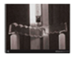 | [10] |
| Low-viscosity glass AM | Soda–Lime | 3-pt Bend | ~70 × 13.1 × 8.5 mm (annealed) | 41 |  | [64] |
| Low-viscosity glass AM | Soda–Lime | 3-pt Bend | ~80 × 13.7 × 9 mm (annealed + chemically tempered) | 41 | 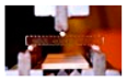 | [64] |
| Low-viscosity glass AM | Soda–Lime | 3-pt Bend | 100 × 13 × 9 mm | 41 ± 15 |  | [15] |
| Low-viscosity glass AM | Soda–Lime | Compressive Loading | 40 × 13 × 9 mm | 254 ± 23 | 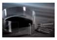 | [15] |
| Manual Fusing | Borosilicate | Cantilever Beam Bending Test | Rod: 3 mm diam. Plate: 3.4 mm thick | 114.6 |  | [24] |
| DED | Silica | Shear Test | Plate: 50.2 × 24.9 × 3.2 mm AM deposit: ~6 mm diameter bead, 23 mm length | 34.5 | 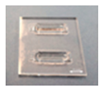 | [102] |
| SLM | Soda–Lime | 3-pt Bend | 1 × 2 × 8 mm | ~6.5 |  | [42] |
| Light-Based | Silica | 3-pt Bend | Truss structure: ~2 × 2 × 4 mm | 187.7 |  | [84] |
| EAM | Soda–Lime | 4-pt Bend | 150 × 40 × 3 mm 0° infill angle | 40 |  | [103] |
| EAM | Soda–Lime | 4-pt Bend | 150 × 40 × 3 mm 45° infill angle | 39 |  | [103] |
| EAM | Soda–Lime | 4-pt Bend | 150 × 40 × 3 mm 90° infill angle | 56 |  | [103] |
4.2. Thermal Properties
4.3. Optical Properties
5. Summary and Future Needs
5.1. Summary
5.2. Challenges and Future Needs
- There is a need for research to develop the scalability and reproducibility of glass AM methods (and associated feedstock material processing) to produce models/components at a larger length scale (i.e., the exploration of glass AM which incorporates one (or more) dimensions that are >300 mm);
- Depending on the method of glass AM employed, achieving (and maintaining) the optical clarity of printed glass objects is a concern for applications that require clarity or complete transparency. This limitation is one that is not, however, specific to glass AM, but an existing limitation of all AM methods (including polymeric EAM, and metal and ceramic AM), with the possible exception of resin-based stereolithography methods;
- Further research in and analysis of postprocessing methods used upon glass AM-produced objects are required. The available information is insufficient in this area, with only incidental exploration of polishing and annealing or artistic techniques documented in the literature. Further exploration of more technical postprocessing presents an opportunity to improve aesthetic, optical, and mechanical properties in parallel with direct process improvements in glass AM;
- Studies should demonstrate the ability to exploit design limits specific to glass printing, such as the overhang angle, resolution of intricacy, capacity for complex topology, and integration of complex features. These have not been demonstrated to date, and have not been correlated with computational models;
- There is a need for a better understanding (and modelling) of the strength of glass in the context of glass AM. Presently, there is a paucity of data in the domain of glass AM with respect to mechanical properties. There is also additional subtlety in mechanical properties across length scales. The performance of full, large-scale elements and objects is essential for art and architecture but is yet to be tested. Whilst component strength is critical, there is also a need to better understand the possibility of interlayer delamination in glass AM, which will require targeted testing;
- Further investigation into the detailed thermal behaviours of deposited glass during printing needs to be performed. Detailed knowledge of thermal behaviour does not exist for the specific area of glass 3D printing, limiting progress with the poor scalability of current implemented methods. The simulation of thermal behaviours and in situ thermal monitoring will provide vital insight, forming a basis for advanced process parameter optimisation;
- Commercial products prepared by glass AM remain in their infancy, and the ongoing (and broader) use of glass AM technology will illuminate further opportunities and prospects. Aspects similar to those in the existing glass industry must be investigated, such as the quality control procedures used for mass-produced glass items, including the reproducibility and consistency of properties;
- There are prospects for machine learning to contribute towards the rapid optimisation of glass AM processing parameters, allowing the accelerated insertion of glass AM technology in commercial products.
Author Contributions
Funding
Institutional Review Board Statement
Informed Consent Statement
Data Availability Statement
Acknowledgments
Conflicts of Interest
References
- Martin, G.; MacFarlane, A. The Glass Bathyscaphe: How Glass Changed the World; Profile Books: London, UK, 2011. [Google Scholar]
- Zhang, D.; Liu, X.; Qiu, J. 3D printing of glass by additive manufacturing techniques: A review. Front. Optoelectron. 2020, 14, 263–277. [Google Scholar] [CrossRef]
- Xin, C.; Li, Z.; Hao, L.; Li, Y. A comprehensive review on additive manufacturing of glass: Recent progress and future outlook. Mater. Des. 2023, 227, 111736. [Google Scholar] [CrossRef]
- Liu, X.; Yang, Y.; Qiu, J. Emerging techniques for customized fabrication of glass. J. Non Cryst. Solids X 2022, 15, 100114. [Google Scholar] [CrossRef]
- Zhang, H.; Huang, L.; Tan, M.; Zhao, S.; Liu, H.; Lu, Z.; Li, J.; Liang, Z. Overview of 3D-Printed Silica Glass. Micromachines 2022, 13, 81. [Google Scholar] [CrossRef]
- Mechanical Metamaterials. Nature. 2022. Available online: https://www.nature.com/collections/iebdeffddc (accessed on 30 May 2024).
- Australian Bureau of Statistics. Waste Account, Australia, Experimental Estimates. ABS. 2018. Available online: https://www.abs.gov.au/statistics/environment/environmental-management/waste-account-australia-experimental-estimates/latest-release (accessed on 30 May 2024).
- Zier, M.; Stenzel, P.; Kotzur, L.; Stolten, D. A review of decarbonization options for the glass industry. Energy Convers. Manag. X 2021, 10, 100083. [Google Scholar] [CrossRef]
- Cummings, K. A History of Glassforming; A. & C. Black: London, UK, 2002. [Google Scholar]
- Klein, J.; Stern, M.; Franchin, G.; Kayser, M.; Inamura, C.; Dave, S.; Weaver, J.C.; Houk, P.; Colombo, P.; Yang, M.; et al. Additive Manufacturing of Optically Transparent Glass. 3d Print. Addit. Manuf. 2015, 2, 92–105. [Google Scholar] [CrossRef]
- Korber, M. COMP4560 Advanced Computing Project; School of Computing, Australian National University: Acton, Australia, 2021; Available online: https://honours-app-56d4c.firebaseapp.com/ (accessed on 30 May 2024).
- Luo, J.; Hostetler, J.M.; Bristow, D.A.; Landers, R.G.; Kinzel, E.C.; Goldstein, J.T. Heat Transfer in Additive Manufacturing of Glass. In Proceedings of the ASME 2017 Heat Transfer Summer Conference, Bellevue, WA, USA, 9–12 July 2017; American Society of Mechanical Engineers Digital Collection: New York, NY, USA, 2017. [Google Scholar] [CrossRef]
- Capps, N.E.; Goldstein, J.T.; Rettschlag, K.; Sleiman, K.; Jaeschke, P.; Kaierle, S.; Kinzel, E.C. Direct laser heating of the filament/substrate interface in digital glass forming. Manuf. Lett. 2022, 31, 106–109. [Google Scholar] [CrossRef]
- Fröhlich, F.; Hildebrand, J.; Bergmann, J.P. Additive Manufacturing with Borosilicate Glass and Soda-Lime Glass. In Proceedings of the 2nd International Conference on Advanced Joining Processes (AJP 2021), Sintra, Portugal, 21–22 October 2021; da Silva, L.F.M., Martins, P.A.F., Reisgen, U., Eds.; Springer International Publishing: Cham, Switzerland, 2022; pp. 151–164. [Google Scholar] [CrossRef]
- Inamura, C.; Stern, M.; Lizardo, D.; Houk, P.; Oxman, N. High Fidelity Additive Manufacturing of Transparent Glass Structures. In Proceedings of the IASS Annual Symposia 2018, Boston, MA, USA, 16–20 July 2018; pp. 1–8. [Google Scholar]
- Norouzi, A.; Rodeman, T.; Paull, B.; Gupta, V. 3D Print and Shrink Microfabrication of Polymer-derived Ceramics: Silicon oxycarbide Glass-Ceramic Microneedles and Microfluidics. chemRxiv 2023. [Google Scholar] [CrossRef]
- Sarmiento, J. Glass 3D Printing for Studio Glass Research and Education. Glass Art Soc. J. 2023, 72–74. Available online: https://issuu.com/glassartsociety/docs/2023_gas_journal (accessed on 18 March 2025).
- Tu, H.; Wei, Z.; Bahrami, A.; Kahla, N.B.; Ahmad, A.; Özkılıç, Y.O. Recent advancements and future trends in 3D concrete printing using waste materials. Dev. Built Environ. 2023, 16, 100187. [Google Scholar] [CrossRef]
- 3D Printed Stainless Steel Bridge. MX3D. n.d. Available online: https://mx3d.com/industries/mx3d-bridge/ (accessed on 30 May 2024).
- Shah, J.; Snider, B.; Clarke, T.; Kozutsky, S.; Lacki, M.; Hosseini, A. Large-scale 3D printers for additive manufacturing: Design considerations and challenges. Int. J. Adv. Manuf. Technol. 2019, 104, 3679–3693. [Google Scholar] [CrossRef]
- Buchanan, C.; Gardner, L. Metal 3D printing in construction: A review of methods, research, applications, opportunities and challenges. Eng. Struct. 2019, 180, 332–348. [Google Scholar] [CrossRef]
- Luo, J.; Pan, H.; Kinzel, E.C. Additive Manufacturing of Glass. J. Manuf. Sci. Eng. 2014, 136, 4028531. [Google Scholar] [CrossRef]
- Rubin, M. Optical properties of soda lime silica glasses. Sol. Energy Mater. 1985, 12, 275–288. [Google Scholar] [CrossRef]
- Seel, M.; Akerboom, R.; Knaack, U.; Oechsner, M.; Hof, P.; Schneider, J. Additive Manufacturing of Glass Components—Exploring the Potential of Glass Connections by Fused Deposition Modeling. Chall. Glass Conf. Proc. 2018, 6, 381–388. [Google Scholar] [CrossRef]
- Seel, M.; Akerboom, R.; Knaack, U.; Oechsner, M.; Hof, P.; Schneider, J. Fused glass deposition modelling for applications in the built environment. Mater. Und Werkst. 2018, 49, 870–880. [Google Scholar] [CrossRef]
- Hostetler, J.M.; Johnson, J.E.; Goldstein, J.T.; Bristow, D.; Landers, R.; Kinzel, E.C. Fiber-Fed Printing of Free-Form Free-Standing Glass Structures. 2018. Available online: https://hdl.handle.net/2152/90180 (accessed on 28 June 2024).
- Curtis, B.; Peters, D.; Hostetler, J.; Landers, R.; Bristow, D.; Kinzel, E.C. Printing Free-Form Free-Standing Glass Structures. In Proceedings of the International Manufacturing Science and Engineering Conference, College Station, TX, USA, 18–22 June 2018; American Society of Mechanical Engineers Digital Collection: New York, NY, USA, 2018. [Google Scholar] [CrossRef]
- Luo, J.; Hostetler, J.M.; Gilbert, L.; Goldstein, J.T.; Urbas, A.M.; Bristow, D.A.; Landers, R.G.; Kinzel, E.C. Additive manufacturing of transparent fused quartz. OE 2018, 57, 041408. [Google Scholar] [CrossRef]
- Luo, J.; Gilbert, L.J.; Qu, C.; Landers, R.G.; Bristow, D.A.; Kinzel, E.C. Additive Manufacturing of Transparent Soda-Lime Glass Using a Filament-Fed Process. J. Manuf. Sci. Eng. 2017, 139, 4035182. [Google Scholar] [CrossRef]
- Luo, J.; Gilbert, L.; Qu, C.; Wilson, J.; Bristow, D.; Landers, R.; Kinzel, E. Wire-Fed Additive Manufacturing of Transparent Glass Parts. In Proceedings of the International Manufacturing Science and Engineering Conference, Guangzhou, China, 28–29 November 2015; American Society of Mechanical Engineers Digital Collection: New York, NY, USA, 2015. [Google Scholar] [CrossRef]
- Luo, J.; Gilbert, L.J.; Bristow, D.A.; Landers, R.G.; Goldstein, J.T.; Urbas, A.M.; Kinzel, E.C. Additive manufacturing of glass for optical applications. In Laser 3D Manufacturing III; Gu, B., Helvajian, H., Piqué, A., Eds.; SPIE: San Francisco, CA, USA, 2016. [Google Scholar] [CrossRef]
- Sleiman, K.; Rettschlag, K.; Jäschke, P.; Kaierle, S.; Overmeyer, L. Experimental Investigation of Additive Manufacturing of Fused Silica Fibers for the Production of Structural Components in the Laser Glass Deposition Process. In Innovative Product Development by Additive Manufacturing 2021; Lachmayer, R., Bode, B., Kaierle, S., Eds.; Springer International Publishing: Cham, Switzerland, 2023; pp. 273–285. [Google Scholar] [CrossRef]
- Luo, J.; Gilbert, L.J.; Peters, D.C.; Bristow, D.A.; Landers, R.G.; Goldstein, J.T.; Urbas, A.M.; Kinzel, E.C. Bubble formation in additive manufacturing of glass. In Advanced Optics for Defense Applications: UV Through LWIR; SPIE: San Francisco, CA, USA, 2016; pp. 86–91. [Google Scholar] [CrossRef]
- Liu, C.; Oriekhov, T.; Fokine, M. Investigation of glass bonding and multi-layer deposition during filament-based glass 3D printing. Front. Mater. 2022, 9, 978861. [Google Scholar] [CrossRef]
- Luo, J.; Bender, T.; Bristow, D.; Landers, R.; Goldstein, J.; Urbas, A.; Kinzel, E. Bubble Formation in Additive Manufacturing of Borosilicate Glass. In Proceedings of the 27th Annual International Solid Freeform Fabrication Symposium, Austin, TX, USA, 8–10 August 2016; pp. 999–1003. [Google Scholar]
- Hostetler, J.M.; Goldstein, J.T.; Bristow, D.; Landers, R.; Kinzel, E.C. Fiber-fed laser-heated process for printing transparent glass from single mode optical fiber. In Laser 3D Manufacturing V; SPIE: San Francisco, CA, USA, 2018; pp. 24–34. [Google Scholar] [CrossRef]
- Sleiman, K.; Rettschlag, K.; Jäschke, P.; Capps, N.; Kinzel, E.C.; Overmeyer, L.; Kaierle, S. Material loss analysis in glass additive manufacturing by laser glass deposition. J. Laser Appl. 2021, 33, 042050. [Google Scholar] [CrossRef]
- Grabe, T.; Lammers, M.; Wang, S.; Wang, X.; Rettschlag, K.; Sleiman, K.; Barroi, A.; Biermann, T.; Ziebehl, A.; Röttger, J.; et al. Additive manufacturing of fused silica using coaxial laser glass deposition: Experiment, simulation, and discussion. In Laser 3D Manufacturing VIII; SPIE: San Francisco, CA, USA, 2021; pp. 45–56. [Google Scholar] [CrossRef]
- Spirrett, F.; Datsiou, K.C.; Magallanes, M.; Ashcroft, I.; Goodridge, R. Powder-fed directed energy deposition of soda lime silica glass on glass substrates. J. Am. Ceram. Soc. 2023, 106, 227–240. [Google Scholar] [CrossRef]
- Maniewski, P.; Laurell, F.; Fokine, M. Laser cladding of transparent fused silica glass using sub-µm powder. Opt. Mater. Express OME 2021, 11, 3056–3070. [Google Scholar] [CrossRef]
- Kayser, M. Solar Sinter. Kayser Works. 2011. Available online: https://kayserworks.com/798817030644 (accessed on 11 April 2024).
- Datsiou, K.C.; Spirrett, F.; Ashcroft, I.; Magallanes, M.; Christie, S.; Goodridge, R. Laser powder bed fusion of soda lime silica glass: Optimisation of processing parameters and evaluation of part properties. Addit. Manuf. 2021, 39, 101880. [Google Scholar] [CrossRef]
- Fateri, M.; Gebhardt, A. Selective Laser Melting of Soda-Lime Glass Powder. Int. J. Appl. Ceram. Technol. 2015, 12, 53–61. [Google Scholar] [CrossRef]
- Kasch, S.; Schmidt, T.; Eichler, F.; Thurn, L.K.; Jahn, S.; Bremen, S. Solution Approaches and Process Concepts for Powder Bed-Based Melting of Glass. In Industrializing Additive Manufacturing; Meboldt, M., Klahn, C., Eds.; Springer International Publishing: Cham, Switzerland, 2021; pp. 82–95. [Google Scholar] [CrossRef]
- Datsiou, K.C.; Saleh, E.; Spirrett, F.; Goodridge, R.; Ashcroft, I.; Eustice, D. Additive manufacturing of glass with laser powder bed fusion. J. Am. Ceram. Soc. 2019, 102, 4410–4414. [Google Scholar] [CrossRef]
- Seyfarth, B.; Schade, L.; Ullsperger, T.; Matthäus, G.; Tünnermann, A.; Nolte, S. Selective laser melting of borosilicate glass using ultrashort laser pulses. In Laser 3D Manufacturing V; SPIE: San Francisco, CA, USA, 2018; pp. 52–57. [Google Scholar] [CrossRef]
- Sander, G.; Jiang, D.; Wu, Y.; Birbilis, N. Exploring the possibility of a stainless steel and glass composite produced by additive manufacturing. Mater. Des. 2020, 196, 109179. [Google Scholar] [CrossRef]
- Chohan, J.S.; Mittal, N.; Kumar, R. Parametric optimization of fused deposition modeling using learning enthusiasm enabled teaching learning based algorithm. SN Appl. Sci. 2020, 2, 1978. [Google Scholar] [CrossRef]
- Baudet, E.; Ledemi, Y.; Larochelle, P.; Morency, S.; Messaddeq, Y. 3D-printing of arsenic sulfide chalcogenide glasses. Opt. Mater. Express OME 2019, 9, 2307–2317. [Google Scholar] [CrossRef]
- Gołębiewski, P.; Wiencław, P.; Cimek, J.; Socha, P.; Pysz, D.; Filipkowski, A.; Stępniewski, G.; Czerwińska, O.; Kujawa, I.; Stępień, R.; et al. 3D soft glass printing of preforms for microstructured optical fibers. Addit. Manuf. 2024, 79, 103899. [Google Scholar] [CrossRef]
- Nan, B.; Gołębiewski, P.; Buczyński, R.; Galindo-Rosales, F.J.; Ferreira, J.M.F. Direct Ink Writing Glass: A Preliminary Step for Optical Application. Materials 2020, 13, 1636. [Google Scholar] [CrossRef]
- Kotz, F.; Arnold, K.; Bauer, W.; Schild, D.; Keller, N.; Sachsenheimer, K.; Nargang, T.M.; Richter, C.; Helmer, D.; Rapp, B.E. Three-dimensional printing of transparent fused silica glass. Nature 2017, 544, 337–339. [Google Scholar] [CrossRef]
- Mader, M.; Hambitzer, L.; Schlautmann, P.; Jenne, S.; Greiner, C.; Hirth, F.; Helmer, D.; Kotz-Helmer, F.; Rapp, B.E. Melt-Extrusion-Based Additive Manufacturing of Transparent Fused Silica Glass. Adv. Sci. 2021, 8, 2103180. [Google Scholar] [CrossRef]
- Nguyen, D.T.; Meyers, C.; Yee, T.D.; Dudukovic, N.A.; Destino, J.F.; Zhu, C.; Duoss, E.B.; Baumann, T.F.; Suratwala, T.; Smay, J.E.; et al. 3D-Printed Transparent Glass. Adv. Mater. 2017, 29, 1701181. [Google Scholar] [CrossRef]
- Arita, R.; Iijima, M.; Fujishiro, Y.; Morita, S.; Furukawa, T.; Tatami, J.; Maruo, S. Rapid three-dimensional structuring of transparent SiO2 glass using interparticle photo-cross-linkable suspensions. Commun. Mater. 2020, 1, 1–7. [Google Scholar] [CrossRef]
- Bauer, J.; Crook, C.; Baldacchini, T. A sinterless, low-temperature route to 3D print nanoscale optical-grade glass. Science 2023, 380, 960–966. [Google Scholar] [CrossRef]
- Zhang, H.; Zhang, Q.; Xiang, P.; Wang, Y.; Lei, J. Direct additive manufacturing of transparent fused silica glasses using an integrated paste printing and laser in-situ melting technology. Addit. Manuf. 2024, 84, 104135. [Google Scholar] [CrossRef]
- von Witzendorff, P.; Pohl, L.; Suttmann, O.; Heinrich, P.; Heinrich, A.; Zander, J.; Bragard, H.; Kaierle, S. Additive manufacturing of glass: CO2-Laser glass deposition printing. Procedia CIRP 2018, 74, 272–275. [Google Scholar] [CrossRef]
- Luo, J.; Gilbert, L.; Qu, C.; Morrow, B.; Bristow, D.; Landers, R.; Goldstein, J.; Urbas, A.; Kinzel, E. Solid Freeform Fabrication of Transparent Fused Quartz using a Filament Fed Process. In Proceedings of the 26th Annual International Solid Freeform Fabrication Symposium, Austin, TX, USA, 10–12 August 2015; pp. 122–133. [Google Scholar]
- Hong, Z.; Luo, T.; Jiang, S.; Liang, R. Fiber-Fed 3D Printing of Germanate Glass Optics. Photonics 2023, 10, 378. [Google Scholar] [CrossRef]
- Grigoriev, S.N.; Khmyrov, R.S.; Gridnev, M.A.; Tarasova, T.V.; Gusarov, A.V. Optimizing the Process Parameters for Additive Manufacturing of Glass Components by Selective Laser Melting: Soda-Lime Glass Versus Quartz Glass. J. Manuf. Sci. Eng. 2021, 144, 4052840. [Google Scholar] [CrossRef]
- Fateri, M.; Gebhardt, A.; Thuemmler, S.; Thurn, L. Experimental Investigation on Selective Laser Melting of Glass. Phys. Procedia 2014, 56, 357–364. [Google Scholar] [CrossRef]
- Seyfarth, B.; Schade, L.; Matthäus, G.; Ullsperger, T.; Heidler, N.; Hilpert, E.; Nolte, S. Laser powder bed fusion of glass: A comparative study between CO2 lasers and ultrashort laser pulses. In Laser 3D Manufacturing VII; SPIE: San Francisco, CA, USA, 2020; pp. 87–92. [Google Scholar] [CrossRef]
- Inamura, C.; Stern, M.; Lizardo, D.; Houk, P.; Oxman, N. Additive Manufacturing of Transparent Glass Structures. 3d Print. Addit. Manuf. 2018, 5, 269–283. [Google Scholar] [CrossRef]
- Zaki, R.M.; Strutynski, C.; Kaser, S.; Bernard, D.; Hauss, G.; Faessel, M.; Sabatier, J.; Canioni, L.; Messaddeq, Y.; Danto, S.; et al. Direct 3D-printing of phosphate glass by fused deposition modeling. Mater. Des. 2020, 194, 108957. [Google Scholar] [CrossRef]
- Carcreff, J.; Cheviré, F.; Galdo, E.; Lebullenger, R.; Gautier, A.; Adam, J.-L.; Coq, D.L.; Brilland, L.; Chahal, R.; Renversez, G.; et al. Elaboration of chalcogenide microstructured optical fibers preform by 3D additive manufacturing. In Optical Components and Materials XVIII; SPIE: San Francisco, CA, USA, 2021; pp. 66–73. [Google Scholar] [CrossRef]
- Troles, J.; Carcreff, J.; Cheviré, F.; Lebullenger, R.; Gautier, A.; Chahal, R.; Calvez, L.; Boussard, C.; Brilland, L.; Charpentier, F.; et al. Fabrication of chalcogenide microstructured optical preforms and fibers by additive manufacturing of chalcogenide glasses. In Optical Components and Materials XX; SPIE: San Francisco, CA, USA, 2023; pp. 9–15. [Google Scholar] [CrossRef]
- Carcreff, J.; Cheviré, F.; Lebullenger, R.; Gautier, A.; Chahal, R.; Adam, J.L.; Calvez, L.; Brilland, L.; Galdo, E.; Le Coq, D.; et al. Investigation on Chalcogenide Glass Additive Manufacturing for Shaping Mid-infrared Optical Components and Microstructured Optical Fibers. Crystals 2021, 11, 228. [Google Scholar] [CrossRef]
- Destino, J.F.; Dudukovic, N.A.; Johnson, M.A.; Nguyen, D.T.; Yee, T.D.; Egan, G.C.; Sawvel, A.M.; Steele, W.A.; Baumann, T.F.; Duoss, E.B.; et al. 3D Printed Optical Quality Silica and Silica–Titania Glasses from Sol–Gel Feedstocks. Adv. Mater. Technol. 2018, 3, 1700323. [Google Scholar] [CrossRef]
- Sasan, K.; Lange, A.; Yee, T.D.; Dudukovic, N.; Nguyen, D.T.; Johnson, M.A.; Herrera, O.D.; Yoo, J.H.; Sawvel, A.M.; Ellis, M.E.; et al. Additive Manufacturing of Optical Quality Germania–Silica Glasses. ACS Appl. Mater. Interfaces 2020, 12, 6736–6741. [Google Scholar] [CrossRef]
- De Marzi, A.; Giometti, G.; Erler, J.; Colombo, P.; Franchin, G. Hybrid additive manufacturing for the fabrication of freeform transparent silica glass components. Addit. Manuf. 2022, 54, 102727. [Google Scholar] [CrossRef]
- Liu, C.; Qian, B.; Ni, R.; Liu, X.; Qiu, J. 3D printing of multicolor luminescent glass. RSC Adv. 2018, 8, 31564–31567. [Google Scholar] [CrossRef]
- Doualle, T.; André, J.-C.; Gallais, L. 3D printing of silica glass through a multiphoton polymerization process. Opt. Lett. OL 2021, 46, 364–367. [Google Scholar] [CrossRef]
- Kotz, F.; Helmer, D.; Rapp, B.E. Additive manufacturing of microfluidic glass chips. In Microfluidics, BioMEMS, and Medical Microsystems XVI; SPIE: San Francisco, CA, USA, 2018; pp. 42–47. [Google Scholar] [CrossRef]
- Liu, C.; Qian, B.; Liu, X.; Tong, L.; Qiu, J. Additive manufacturing of silica glass using laser stereolithography with a top-down approach and fast debinding. RSC Adv. 2018, 8, 16344–16348. [Google Scholar] [CrossRef]
- Cooperstein, I.; Shukrun, E.; Press, O.; Kamyshny, A.; Magdassi, S. Additive Manufacturing of Transparent Silica Glass from Solutions. ACS Appl. Mater. Interfaces 2018, 10, 18879–18885. [Google Scholar] [CrossRef]
- Cai, P.; Guo, L.; Wang, H.; Li, J.; Li, J.; Qiu, Y.; Zhang, Q.; Lue, Q. Effects of slurry mixing methods and solid loading on 3D printed silica glass parts based on DLP stereolithography. Ceram. Int. 2020, 46, 16833–16841. [Google Scholar] [CrossRef]
- Kotz, F.; Arnold, K.; Risch, P.; Rapp, B.E. Next-generation 3D printing of glass: The emergence of enabling materials. In Advanced Manufacturing Technologies for Micro- and Nanosystems in Security and Defence; SPIE: San Francisco, CA, USA, 2018; pp. 27–32. [Google Scholar] [CrossRef]
- Li, Z.; Jia, Y.; Duan, K.; Xiao, R.; Qiao, J.; Liang, S.; Wang, S.; Chen, J.; Wu, H.; Lu, Y.; et al. One-photon three-dimensional printed fused silica glass with sub-micron features. Nat. Commun. 2024, 15, 2689. [Google Scholar] [CrossRef]
- Yang, J.; Feng, M.; Chen, Z.; Xu, R.; Khan, A.; Zhang, K.; Han, D.; Sang, X.; Xie, J.; Liu, L.; et al. Printing adaptability and vitrification of UV photo-responsive silica nanocomposites. Mater. Res. Bull. 2023, 158, 112046. [Google Scholar] [CrossRef]
- Cai, P.; Guo, L.; Liu, L.; Zhang, Q.; Li, J.; Lue, Q. Rapid manufacturing of silica glass parts with complex structures through stereolithography and pressureless spark plasma sintering. Ceram. Int. 2022, 48, 55–63. [Google Scholar] [CrossRef]
- Chu, Y.; Fu, X.; Luo, Y.; Canning, J.; Tian, Y.; Cook, K.; Zhang, J.; Peng, G.-D. Silica optical fiber drawn from 3D printed preforms. Opt. Lett. OL 2019, 44, 5358–5361. [Google Scholar] [CrossRef]
- Kotz, F.; Quick, A.S.; Risch, P.; Martin, T.; Hoose, T.; Thiel, M.; Helmer, D.; Rapp, B.E. Two-Photon Polymerization of Nanocomposites for the Fabrication of Transparent Fused Silica Glass Microstructures. Adv. Mater. 2021, 33, 2006341. [Google Scholar] [CrossRef]
- Toombs, J.T.; Luitz, M.; Cook, C.C.; Jenne, S.; Li, C.C.; Rapp, B.E.; Kotz-Helmer, F.; Taylor, H.K. Volumetric additive manufacturing of silica glass with microscale computed axial lithography. Science 2022, 376, 308–312. [Google Scholar] [CrossRef]
- Klein, J.; Franchin, G.; Stern, M.; Kayser, M.; Inamura, C.; Dave, S.; Oxman, N.; Houk, P. Methods and Apparatus for Additive Manufacturing of Glass. US10266442B2, 23 April 2019. Available online: https://patents.google.com/patent/US10266442B2/en/ (accessed on 30 May 2024).
- Zhao, H.; Zu, C.; Liu, Y.; Zhao, H.; Zhou, P.; Cao, Y. A Kind of 3D Printing Device for Chalcogenide Glass Element. CN106116120B, 28 September 2018. Available online: https://patents.google.com/patent/CN106116120B/en (accessed on 30 May 2024).
- Drewnowski, C.W.; Harding, T.N.; Laskowski, C.M.; Matusick, J.M.; Morgan, K.S.; Peris, J.P.; Peterson, I.M.; Sonner, T.M. Additive Manufacturing Systems and Method for Making Glass Articles. US20210101818A1, 8 April 2021. Available online: https://patents.google.com/patent/US20210101818A1/en (accessed on 30 May 2024).
- Bracha, A.E. GAL-OR, 3d Printing System for Printing High Melting Temperature Materials. WO2018163006A1, 26 February 2018. Available online: https://patents.google.com/patent/WO2018163006A1/en (accessed on 30 May 2024).
- Birbilis, N.; Feenstra, D.R.; Koutsonikolas, T. Three-Dimensional Printing System. AU2021289614A1, 9 February 2023. Available online: https://patents.google.com/patent/AU2021289614A1/en?q=(%22maple+glass+printing%22)&oq=%22maple+glass+printing%22 (accessed on 30 May 2024).
- Shelby, J.E. Introduction to Glass Science and Technology; Royal Society of Chemistry: London, UK, 2015. [Google Scholar]
- Cascade. Evenline. n.d. Available online: https://www.evenline.co/product/cascade (accessed on 30 May 2024).
- Oxman, N. Glass I, Oxman. 2015. Available online: https://oxman.com/projects/glass-i (accessed on 31 May 2024).
- Azzarello, N. Stefanie Pender Teaches a Robot the Art of Glassmaking. Designboom. 2017. Available online: https://www.designboom.com/art/stefanie-pender-robot-glassmaking-autodesk-04-17-2017/ (accessed on 10 April 2024).
- Bullseye Glass Co. The Vitrigraph Kiln. 2013. Available online: https://www.bullseyeglass.com/wp-content/uploads/2023/02/technotes_02.pdf (accessed on 28 June 2024).
- Sher, D. MICRON3DP Co-Founder Discusses Shift from Glass to MIM-Based Additive Manufacturing. VoxelMatters—The Heart of Additive Manufacturing. 2018. Available online: https://www.voxelmatters.com/co-founder-micron3dp-mim/ (accessed on 10 April 2024).
- Prior, M. 3D Printed Glass Is on Display in Venice, 3Dnatives. 2022. Available online: https://www.3dnatives.com/en/3d-printed-glass-venice-glass-week-031020225/ (accessed on 30 May 2024).
- Bigerl, J. 3D Printed Fashion on Instagram: “The Accessories 3D Printed from Recycled Material Have Integrated Glass Prints as an Eye Catcher. The Recycled Glass Prints Were Realized Together with Hannes Erler and Created with Swarovski’s 3D Glass Printing Technology. @hannes_erler @swarovski model: Pia prost @pia_prost photos: Omram bhagchandani @o.m.r.a.m”. Instagram. 2021. Available online: https://www.instagram.com/p/CW-WuZAIflX/ (accessed on 30 May 2024).
- Xuanzhao, P.; Radionova, A.; Wei, Y.; Schartner, E.; Koutsonikolas, T.; Ebendorff-Heidepriem, H. 3D Printing Bullseye Glass Preform for Fibre Drawing. Adelaide. 2022. Available online: https://indico.cern.ch/event/1131431/contributions/5044890/ (accessed on 16 January 2025).
- Cook, K.; Canning, J.; Leon-Saval, S.; Reid, Z.; Hossain, M.A.; Comatti, J.-E.; Luo, Y.; Peng, G.-D. Air-structured optical fiber drawn from a 3D-printed preform. Opt. Lett. 2015, 40, 3966. [Google Scholar] [CrossRef]
- Cook, K.; Balle, G.; Canning, J.; Chartier, L.; Athanaze, T.; Hossain, M.A.; Han, C.; Comatti, J.-E.; Luo, Y.; Peng, G.-D. Step-index optical fiber drawn from 3D printed preforms. Opt. Lett. 2016, 41, 4554. [Google Scholar] [CrossRef] [PubMed]
- Bisect Large, Evenline, n.d. Available online: https://www.evenline.co/product/bisect-large (accessed on 30 May 2024).
- Chhadeh, P.; Sleiman, K.; Lautenschläger, I.; Rettschlag, K.; Jäschke, P.; Kaierle, S.; Knaack, U.; Seel, M. Investigation of the Joining Area of Additive Manufactured Glass Structures on Flat Glass. Glass Performance Days. 2023. Available online: https://www.glassonweb.com/article/investigation-joining-area-additive-manufactured-glass-structures-flat-glass (accessed on 18 March 2025).
- Nowak, E.G. Optimization of Glass Plate Structures with Additive Manufacturing. Bachelor’s Thesis, Technische Universität Darmstadt, Darmstadt, Germany, 2024. [Google Scholar]
- Viskanta, R.; Anderson, E.E. Heat Transfer in Semitransparent Solids. In Advances in Heat Transfer; Irvine, T.F., Hartnett, J.P., Eds.; Elsevier: Amsterdam, The Netherlands, 1975; pp. 317–441. [Google Scholar] [CrossRef]
- Fotheringham, U. Thermal Properties of Glass. In The Properties of Optical Glass; Bach, H., Neuroth, N., Eds.; Springer: Berlin/Heidelberg, Germany, 1998; pp. 201–228. [Google Scholar] [CrossRef]
- Field, R.E.; Viskanta, R. Measurement and Prediction of the Dynamic Temperature Distributions in Soda-Lime Glass Plates. J. Am. Ceram. Soc. 1990, 73, 2047–2053. [Google Scholar] [CrossRef]
- ANSYS, Inc. Ansys® Fluent, Help System, Discrete Ordinates (DO) Radiation Model Theory; ANSYS, Inc.: Canonsburg, PA, USA, 2025. [Google Scholar]
- Raithby, G.D.; Chui, E.H. A Finite-Volume Method for Predicting a Radiant Heat Transfer in Enclosures With Participating Media. J. Heat Transf. 1990, 112, 415–423. [Google Scholar] [CrossRef]
- Chui, E.H.; Raithby, G.D. Computation of Radiant Heat Transfer on a Nonorthogonal Mesh Using the Finite-Volume Method. Numer. Heat Transf. Part B Fundam. 1993, 23, 269–288. [Google Scholar] [CrossRef]
- Murthy, J.Y.; Mathur, S.R. Finite Volume Method for Radiative Heat Transfer Using Unstructured Meshes. J. Thermophys. Heat Transf. 1998, 12, 313–321. [Google Scholar] [CrossRef]
- Liu, C.; Oriekhov, T.; Lee, C.; Harvey, C.M.; Fokine, M. Rapid Fabrication of Silica Microlens Arrays via Glass 3D Printing. 3d Print. Addit. Manuf. 2024, 11, 460–466. [Google Scholar] [CrossRef] [PubMed]


Disclaimer/Publisher’s Note: The statements, opinions and data contained in all publications are solely those of the individual author(s) and contributor(s) and not of MDPI and/or the editor(s). MDPI and/or the editor(s) disclaim responsibility for any injury to people or property resulting from any ideas, methods, instructions or products referred to in the content. |
© 2025 by the authors. Licensee MDPI, Basel, Switzerland. This article is an open access article distributed under the terms and conditions of the Creative Commons Attribution (CC BY) license (https://creativecommons.org/licenses/by/4.0/).
Share and Cite
Shaw, M.; Vlahopoulos, D.; Usma-Mansfield, C.; Sarmiento, J.; Snooks, R.; Koutsonikolas, T.; Birbilis, N. The Additive Manufacturing of Glass: A Critical Review. Appl. Sci. 2025, 15, 3414. https://doi.org/10.3390/app15063414
Shaw M, Vlahopoulos D, Usma-Mansfield C, Sarmiento J, Snooks R, Koutsonikolas T, Birbilis N. The Additive Manufacturing of Glass: A Critical Review. Applied Sciences. 2025; 15(6):3414. https://doi.org/10.3390/app15063414
Chicago/Turabian StyleShaw, Mackinley, Dylan Vlahopoulos, Clara Usma-Mansfield, Jeffrey Sarmiento, Roland Snooks, Tony Koutsonikolas, and Nick Birbilis. 2025. "The Additive Manufacturing of Glass: A Critical Review" Applied Sciences 15, no. 6: 3414. https://doi.org/10.3390/app15063414
APA StyleShaw, M., Vlahopoulos, D., Usma-Mansfield, C., Sarmiento, J., Snooks, R., Koutsonikolas, T., & Birbilis, N. (2025). The Additive Manufacturing of Glass: A Critical Review. Applied Sciences, 15(6), 3414. https://doi.org/10.3390/app15063414