
Compliant and Seamless Hybrid (Star and Mesh) Network Topology Coexistence for LoRaWAN: A Proof of Concept

 ,
,  , and
, and
Abstract
1. Introduction
- The proposal of a straightforward approach for LoRaWAN, enabling the coexistence of star and mesh network topologies (hybrid) completely compliant with the LoRaWAN standard and seamless to IoT applications.
- The provision of a topology manager to assess network link quality and the decision to change the role of end devices to single-hop or multiple-hop transmission modes.
- As a consequence of the previous point, an end device code integrates star, mesh, and hybrid topology states to perform the changes in the transmission modes.
- The addition of a control user interface to customize the parameters used by the topology manager and allow the user to change transmission mode at will.
2. Related Work
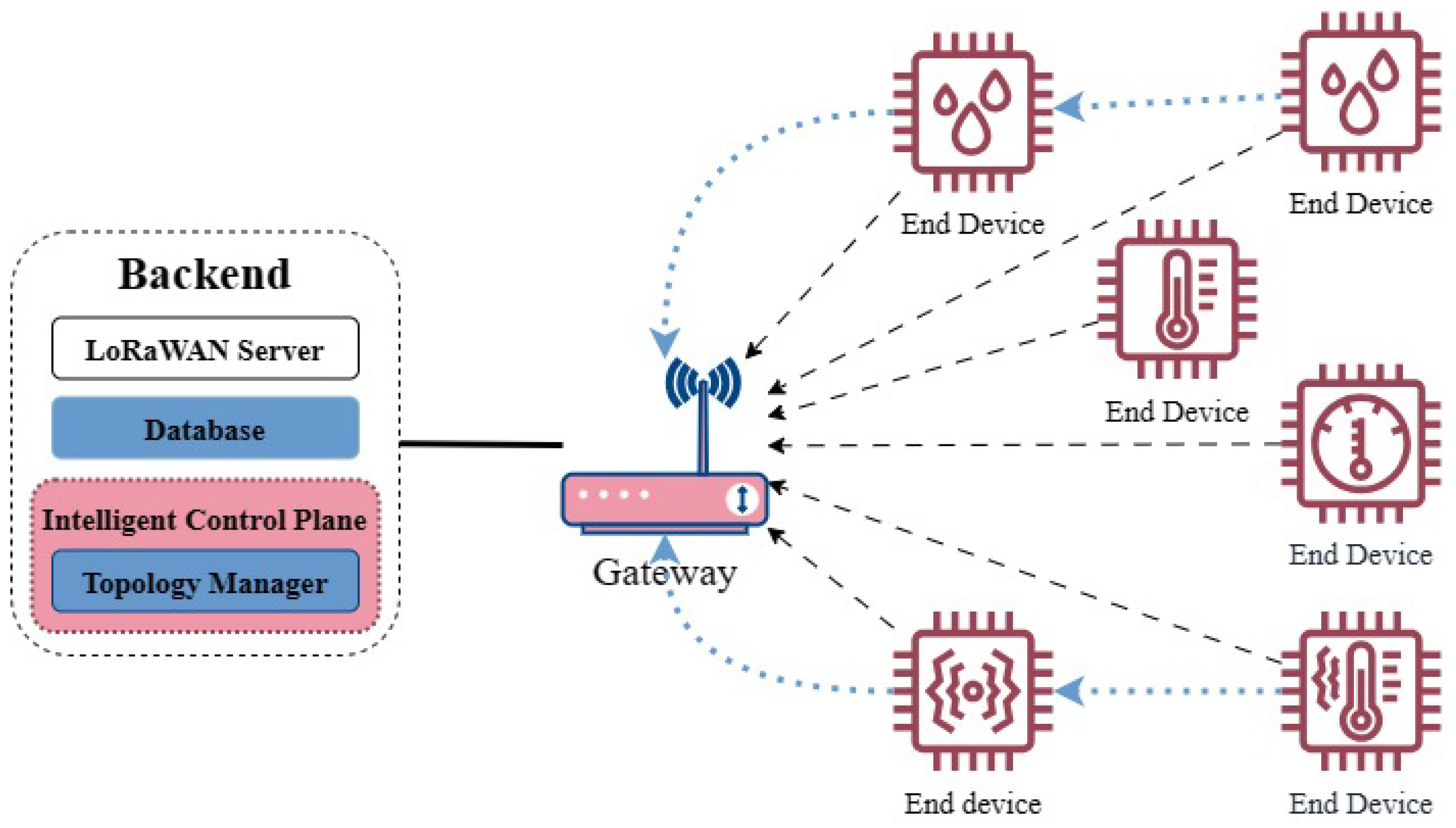
3. Hybrid Topology Architecture
3.1. Procedure Description
3.2. Implementation
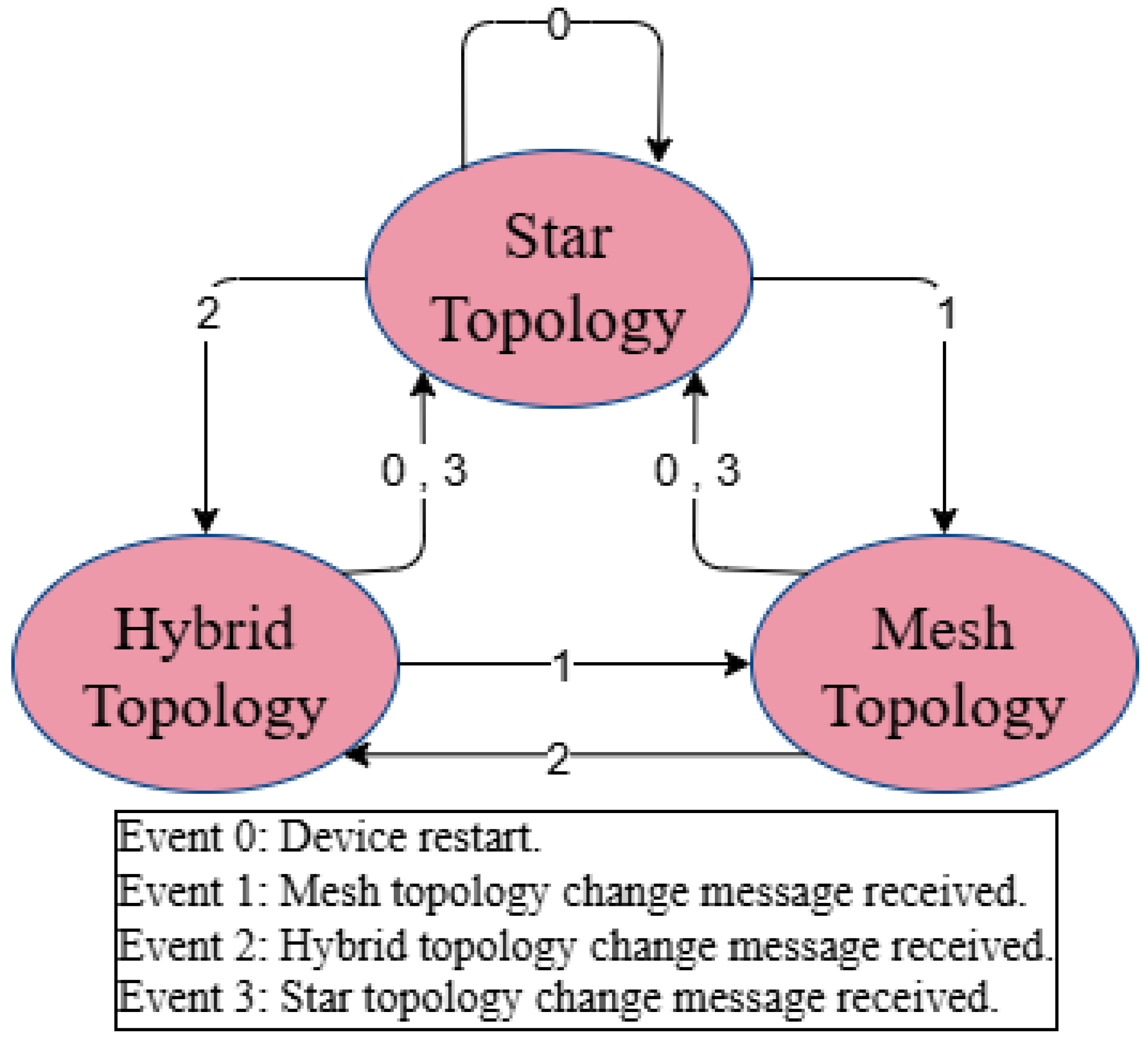
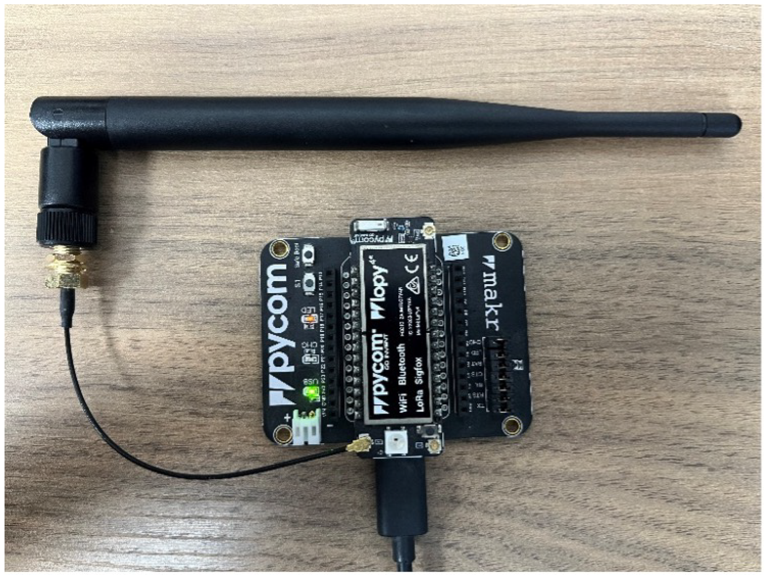
3.2.1. End Devices
3.2.2. Gateway
3.2.3. LoRaWAN Server
3.2.4. MQTT Broker
3.2.5. Database Module
3.2.6. Topology Manager
| Algorithm 1 Adaptive Topology Adjustment |
|
3.2.7. Control User Interface
4. Experiment Design
5. Results
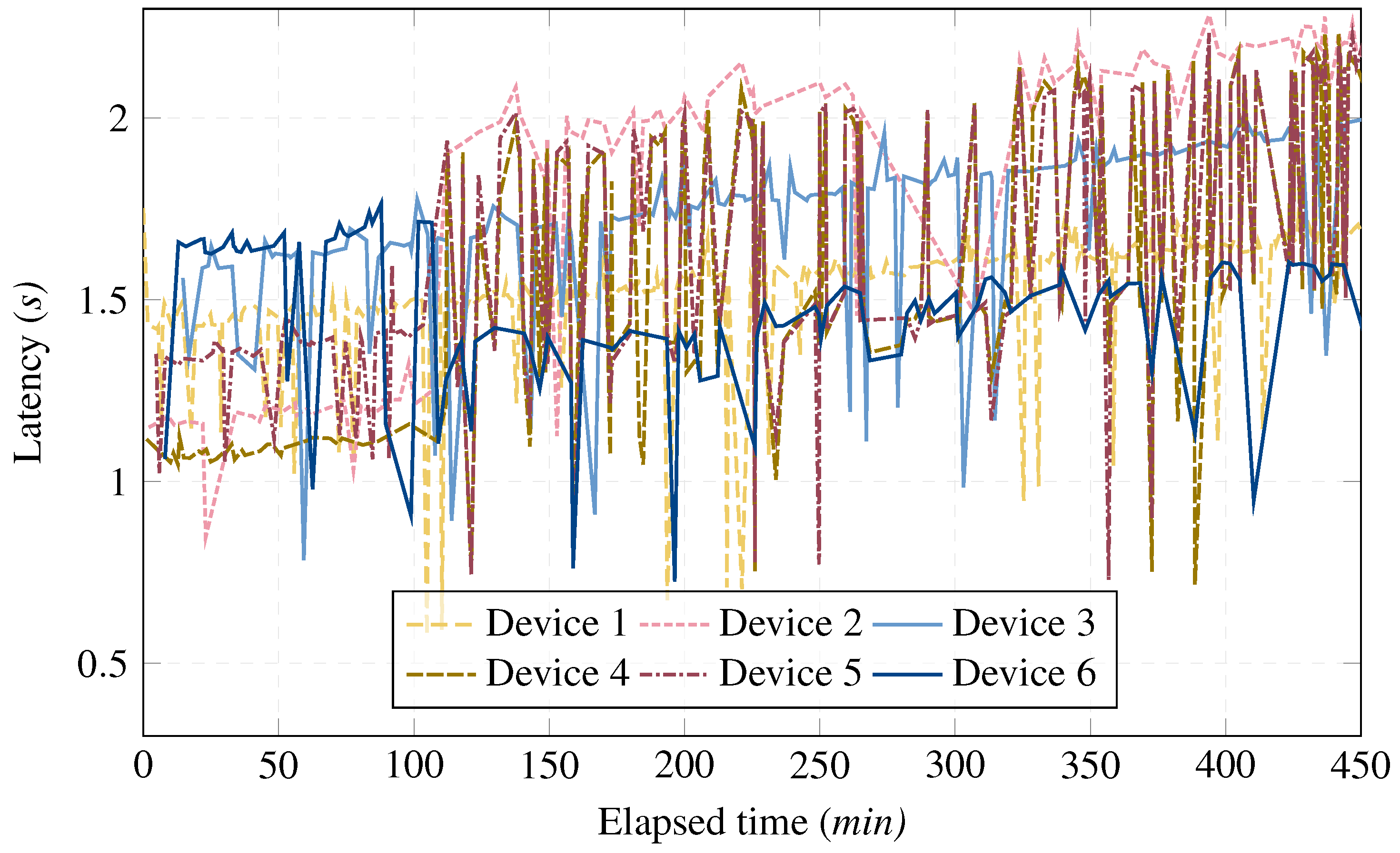
5.1. Scenario 1
5.2. Scenario 2
5.3. Scenario 3
6. Conclusions
Author Contributions
Funding
Institutional Review Board Statement
Informed Consent Statement
Data Availability Statement
Conflicts of Interest
References
- LoRa Alliance. Available online: https://lora-alliance.org/ (accessed on 24 February 2025).
- The Things Network. Available online: https://www.thethingsnetwork.org/ (accessed on 24 February 2025).
- Basford, P.J.; Bulot, F.M.; Apetroaie-Cristea, M.; Cox, S.J.; Ossont, S.J. LoRaWAN for smart city IoT deployments: A long term evaluation. Sensors 2020, 20, 648. [Google Scholar] [CrossRef] [PubMed]
- Sisinni, E.; Carvalho, D.F.; Ferrari, P. Emergency communication in IoT scenarios by means of a transparent LoRaWAN enhancement. IEEE Internet Things J. 2020, 7, 10684–10694. [Google Scholar]
- LoRa Alliance Technical Comittee Regional Parameters Workgroup. LoRaWAN 1.0.3 Regional Parameters; LoRa Alliance: Fremont, CA, USA, 2018. [Google Scholar]
- Todoli-Ferrandis, D.; Silvestre-Blanes, J.; Sempere-Payá, V.; Planes-Martinez, A. Analysis of bidirectional ADR-enabled class B LoRaWAN networks in industrial scenarios. Appl. Sci. 2020, 10, 7964. [Google Scholar] [CrossRef]
- Luvisotto, M.; Tramarin, F.; Vangelista, L.; Vitturi, S. On the use of LoRaWAN for indoor industrial IoT applications. Wirel. Commun. Mob. Comput. 2018, 2018, 3982646. [Google Scholar]
- Marquez, L.E.; Osorio, A.; Calle, M.; Velez, J.C.; Serrano, A.; Candelo-Becerra, J.E. On the use of LoRaWAN in smart cities: A study with blocking interference. IEEE Internet Things J. 2019, 7, 2806–2815. [Google Scholar]
- Schroder Filho, H.; Pissolato Filho, J.; Moreli, V. The adequacy of LoRaWAN on smart grids: A comparison with RF mesh technology. In Proceedings of the 2016 IEEE International Smart Cities Conference (ISC2), Trento, Italy, 12–15 September 2016; pp. 1–6. [Google Scholar]
- Singh, R.K.; Aernouts, M.; De Meyer, M.; Weyn, M.; Berkvens, R. Leveraging LoRaWAN technology for precision agriculture in greenhouses. Sensors 2020, 20, 1827. [Google Scholar] [CrossRef]
- Liu, J.; Gao, J.; Jha, S.; Hu, W. Seirios: Leveraging multiple channels for LoRaWAN indoor and outdoor localization. In Proceedings of the 27th Annual International Conference on Mobile Computing and Networking, New Orleans, LA, USA, 25–29 October 2021; pp. 656–669. [Google Scholar]
- Sherazi, H.H.R.; Grieco, L.A.; Imran, M.A.; Boggia, G. Energy-efficient LoRaWAN for industry 4.0 applications. IEEE Trans. Ind. Inform. 2020, 17, 891–902. [Google Scholar]
- Gaitan, N.C. A long-distance communication architecture for medical devices based on LoRaWAN protocol. Electronics 2021, 10, 940. [Google Scholar] [CrossRef]
- Haxhibeqiri, J.; De Poorter, E.; Moerman, I.; Hoebeke, J. A survey of LoRaWAN for IoT: From technology to application. Sensors 2018, 18, 3995. [Google Scholar] [CrossRef]
- Adelantado, F.; Vilajosana, X.; Tuset-Peiro, P.; Martinez, B.; Melia-Segui, J.; Watteyne, T. Understanding the limits of LoRaWAN. IEEE Commun. Mag. 2017, 55, 34–40. [Google Scholar]
- Soto-Vergel, A.; Arismendy, L.; Bornacelli-Durán, R.; Cardenas, C.; Montero-Arévalo, B.; Rivera, E.; Calle, M.; Candelo-Becerra, J.E. LoRa performance in industrial environments: Analysis of different ADR algorithms. IEEE Trans. Ind. Inform. 2023, 19, 10501–10511. [Google Scholar]
- Farooq, M.O. Clustering-based layering approach for uplink multi-hop communication in LoRa networks. IEEE Netw. Lett. 2020, 2, 132–135. [Google Scholar]
- Lalle, Y.; Fourati, M.; Fourati, L.C.; Barraca, J.P. Routing strategies for LoRaWAN multi-hop networks: A survey and an SDN-based solution for smart water grid. IEEE Access 2021, 9, 168624–168647. [Google Scholar]
- Alvarado-Alcon, F.J.; Asorey-Cacheda, R.; Garcia-Sanchez, A.J.; Garcia-Haro, J. Carbon Footprint vs Energy Optimization in IoT Network Deployments. IEEE Access 2022, 10, 111297–111309. [Google Scholar]
- Aslam, M.S.; Khan, A.; Atif, A.; Hassan, S.A.; Mahmood, A.; Qureshi, H.K.; Gidlund, M. Exploring multi-hop LoRa for green smart cities. IEEE Netw. 2019, 34, 225–231. [Google Scholar]
- Choi, R.; Lee, S.; Lee, S. Reliability improvement of lora with arq and relay node. Symmetry 2020, 12, 552. [Google Scholar] [CrossRef]
- Liao, C.H.; Zhu, G.; Kuwabara, D.; Suzuki, M.; Morikawa, H. Multi-hop LoRa networks enabled by concurrent transmission. IEEE Access 2017, 5, 21430–21446. [Google Scholar]
- Kim, H.; Kim, H.; Baek, S.; Melenchuk, R.; Soroka, J.; Smith, A. Hybrid LoRa Network Architecture: Automatic Switching between LoRaWAN and LoRa Mesh Network in Environments with Dynamic Obstacle Variations. In Proceedings of the 2024 33rd International Conference on Computer Communications and Networks (ICCCN), Big Island, HI, USA, 29–31 July 2024; pp. 1–6. [Google Scholar]
- Resources LoRa Alliance. TS011-1.0.0 Relay. Available online: https://resources.lora-alliance.org/technical-specifications/ts011-1-0-0-relay (accessed on 24 February 2025).
- Lee, H.C.; Ke, K.H. Monitoring of large-area IoT sensors using a LoRa wireless mesh network system: Design and evaluation. IEEE Trans. Instrum. Meas. 2018, 67, 2177–2187. [Google Scholar] [CrossRef]
- Pan, M.; Chen, C.; Yin, X.; Huang, Z. UAV-aided emergency environmental monitoring in infrastructure-less areas: LoRa mesh networking approach. IEEE Internet Things J. 2021, 9, 2918–2932. [Google Scholar]
- Ebi, C.; Schaltegger, F.; Rüst, A.; Blumensaat, F. Synchronous LoRa mesh network to monitor processes in underground infrastructure. IEEE Access 2019, 7, 57663–57677. [Google Scholar]
- Lloret, J.; García, L.; Jimenez, J.M.; Sendra, S.; Lorenz, P. Cluster-based communication protocol and architecture for a wastewater purification system intended for irrigation. IEEE Access 2021, 9, 142374–142389. [Google Scholar]
- Hong, S.; Yao, F.; Ding, Y.; Yang, S.H. A hierarchy-based energy-efficient routing protocol for LoRa-Mesh network. IEEE Internet Things J. 2022, 9, 22836–22849. [Google Scholar]
- Solé, J.M.; Centelles, R.P.; Freitag, F.; Meseguer, R. Implementation of a LoRa mesh library. IEEE Access 2022, 10, 113158–113171. [Google Scholar]
- Veloso, A.F.d.S.; Júnior, J.V.R.; Rabelo, R.d.A.L.; Silveira, J.D.f. HyDSMaaS: A Hybrid Communication Infrastructure with LoRaWAN and LoraMesh for the Demand Side Management as a Service. Future Internet 2021, 13, 271. [Google Scholar] [CrossRef]
- Sisinni, E.; Ferrari, P.; Carvalho, D.F.; Rinaldi, S.; Marco, P.; Flammini, A.; Depari, A. LoRaWAN range extender for industrial IoT. IEEE Trans. Ind. Inform. 2019, 16, 5607–5616. [Google Scholar]
- Zhou, W.; Tong, Z.; Dong, Z.Y.; Wang, Y. LoRa-Hybrid: A LoRaWAN Based multihop solution for regional microgrid. In Proceedings of the 2019 IEEE 4th International Conference on Computer and Communication Systems (ICCCS), Singapore, 23–25 February 2019; pp. 650–654. [Google Scholar]
- Almeida, N.C.; Rolle, R.P.; Godoy, E.P.; Ferrari, P.; Sisinni, E. Proposal of a hybrid LoRa Mesh/LoRaWAN network. In Proceedings of the 2020 IEEE International Workshop on Metrology for Industry 4.0 & IoT, Rome, Italy, 3–5 June 2020; pp. 702–707. [Google Scholar]
- Code Visual Studio. Code Editing. Available online: https://code.visualstudio.com/ (accessed on 24 February 2025).
- Marketplace Visual Studio. Pymakr. Available online: https://marketplace.visualstudio.com/items?itemName=pycom.Pymakr (accessed on 24 February 2025).
- Wifx IoT. LORIX One LoRaWAN Gateway. Available online: https://iot.wifx.net/en/products/lorix-one/ (accessed on 24 February 2025).
- ChirpStack Open-Source. LoRaWAN Network Server. Available online: https://www.chirpstack.io/ (accessed on 24 February 2025).
- Mosquitto. Eclipse. Available online: https://mosquitto.org/ (accessed on 24 February 2025).
- MongoDB: The Developer Data Platform. Available online: https://www.mongodb.com/ (accessed on 24 February 2025).


| Reference | Protocol | Topology | Topology Coexistence | Dynamic Network Configuration |
|---|---|---|---|---|
| [31] | LoRaWAN/LoRaMesh | Star and mesh | Yes | No |
| [33] | LoRaWAN | Multi-hop (Relay) | No | No |
| [23] | LoRaWAN/LoRaMesh | Star and mesh | No (switches from only star to only mesh) | Yes (complete network) |
| [34] | LoRaWAN/LoRaMesh | Star and mesh | Yes | No |
| Our proposal | LoRaWAN | Star and mesh | Yes | Yes (device per device) |
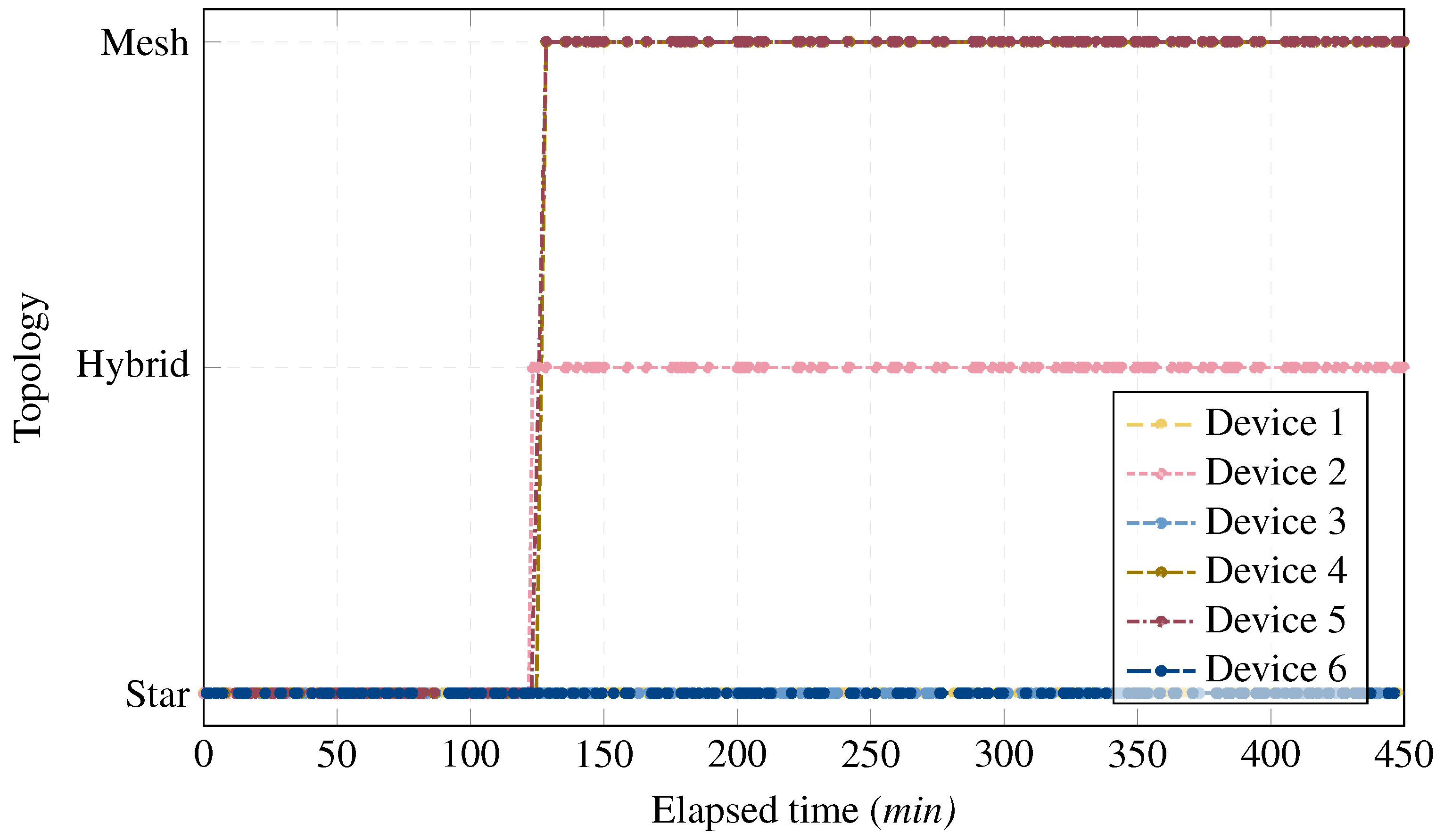
| Transmission Mode | Topology Mode |
|---|---|
| Single-hop | Star |
| Multi-hop | Hybrid |
| Mesh |
| Metric | Device | Minimum | Maximum | Average | Variance |
|---|---|---|---|---|---|
| Latency (s) | 1 | 0.6 | 1.8 | 1.5 | 0.03 |
| 2 | 0.8 | 2.4 | 1.8 | 0.19 | |
| 3 | 0.8 | 2 | 1.7 | 0.06 | |
| 4 | 0.7 | 2.3 | 1.6 | 0.17 | |
| 5 | 0.7 | 2.3 | 1.7 | 0.14 | |
| 6 | 0.7 | 1.8 | 1.5 | 0.04 | |
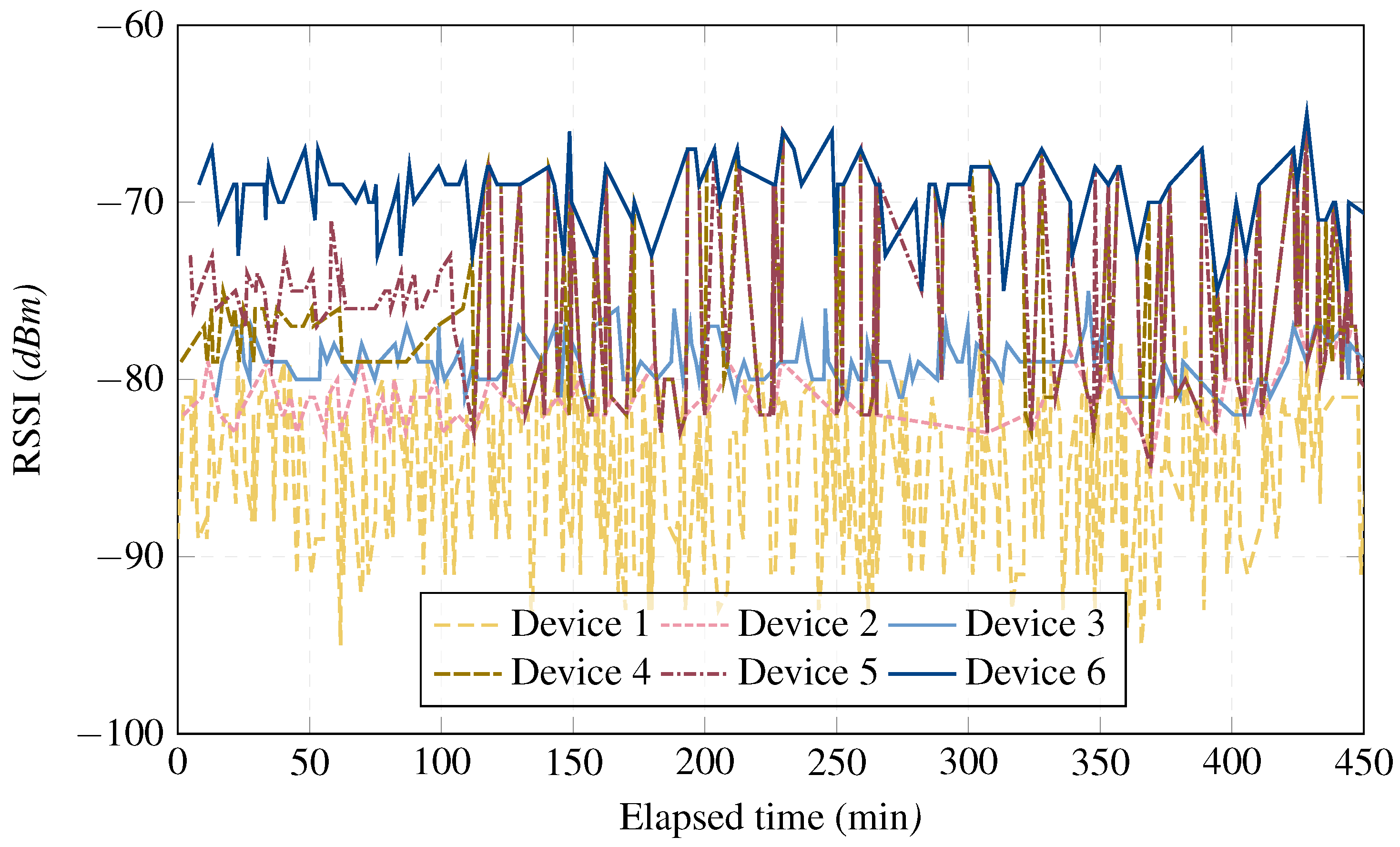
| RSSI (dBm) | 1 | −95 | −77 | −85.4 | 20.15 |
| 2 | −85 | −77 | −80.7 | 3.07 | |
| 3 | −82 | −75 | −79 | 1.87 | |
| 4 | −85 | −65 | −75.7 | 28.68 | |
| 5 | −85 | −65 | −75.5 | 27.42 | |
| 6 | −81 | −65 | −69.8 | 6.22 | |
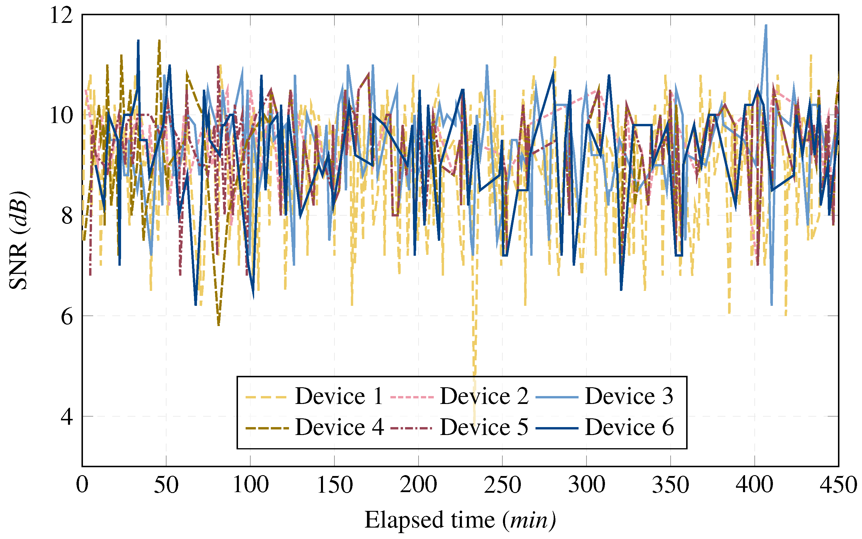
| SNR (dB) | 1 | 3.8 | 11.2 | 8.9 | 1.4 |
| 2 | 7 | 11 | 9.4 | 0.62 | |
| 3 | 6.2 | 11.8 | 9.3 | 0.87 | |
| 4 | 5.8 | 11.5 | 9.3 | 1.05 | |
| 5 | 6.5 | 11 | 9.3 | 0.95 | |
| 6 | 6.2 | 11.5 | 9.2 | 1.3 |
| Metric | Device | Minimum | Maximum | Average | Variance |
|---|---|---|---|---|---|
| Latency (s) | 1 | 1 | 2.1 | 1.8 | 0.02 |
| 2 | 0.7 | 3.2 | 2.4 | 0.62 | |
| 3 | 1.2 | 2.6 | 2.2 | 0.04 | |
| 4 | 1.2 | 3.1 | 2.6 | 0.3 | |
| 5 | 0.7 | 3.1 | 2.3 | 0.77 | |
| 6 | 0.9 | 2.1 | 1.8 | 0.04 | |
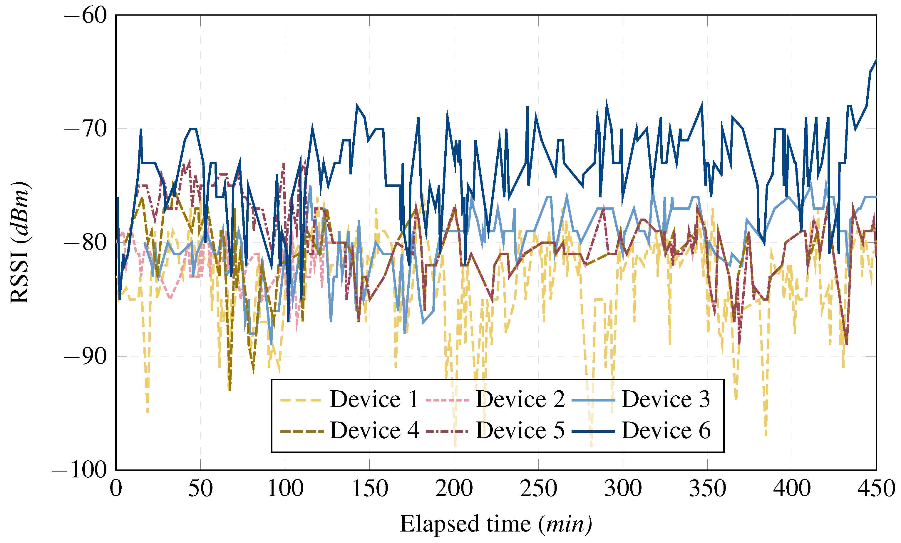
| RSSI (dBm) | 1 | −98 | −76 | −83 | 17.24 |
| 2 | −89 | −77 | −81.2 | 6.04 | |
| 3 | −89 | −75 | −79.7 | 9.68 | |
| 4 | −93 | −75 | −80.9 | 9.74 | |
| 5 | −89 | −73 | −79.6 | 11.06 | |
| 6 | −87 | −63 | −73.7 | 17.56 | |
| SNR (dB) | 1 | 3.5 | 11 | 9 | 1.37 |
| 2 | 5.8 | 11.5 | 9 | 1.15 | |
| 3 | 6.2 | 11.8 | 9.5 | 1.13 | |
| 4 | 5.8 | 11.5 | 9.1 | 1.08 | |
| 5 | 5.8 | 11.5 | 9.2 | 1.05 | |
| 6 | 6 | 11.8 | 9.3 | 1.47 |
| Metric | Device | Minimum | Maximum | Average | Variance |
|---|---|---|---|---|---|
| Latency (s) | 1 | 1.4 | 2.3 | 2.2 | 0.02 |
| 2 | 0.8 | 2.2 | 1.7 | 0.05 | |
| 3 | 1.5 | 2.5 | 2.3 | 0.03 | |
| 4 | 1.2 | 2.3 | 1.9 | 0.03 | |
| 5 | 0.7 | 2.3 | 1.7 | 0.12 | |
| 6 | 1.3 | 2.4 | 2.1 | 0.05 | |
| RSSI (dBm) | 1 | −99 | −83 | −89.4 | 10.51 |
| 2 | −86 | −76 | −89.4 | 10.51 | |
| 3 | −103 | −79 | −90.7 | 27.09 | |
| 4 | −79 | −69 | −73.81 | 3.09 | |
| 5 | −95 | −70 | −78.53 | 26.70 | |
| 6 | −88 | −69 | −75.41 | 10.62 | |
| SNR (dB) | 1 | 4.5 | 11.2 | 8.6 | 1.44 |
| 2 | 5.8 | 11.8 | 9.4 | 0.87 | |
| 3 | 1.2 | 11 | 8.22 | 3.19 | |
| 4 | 6.8 | 11.5 | 9.5 | 0.78 | |
| 5 | 6.2 | 11 | 9.4 | 0.85 | |
| 6 | 6.2 | 11.5 | 9.1 | 1.38 |
Disclaimer/Publisher’s Note: The statements, opinions and data contained in all publications are solely those of the individual author(s) and contributor(s) and not of MDPI and/or the editor(s). MDPI and/or the editor(s) disclaim responsibility for any injury to people or property resulting from any ideas, methods, instructions or products referred to in the content. |
© 2025 by the authors. Licensee MDPI, Basel, Switzerland. This article is an open access article distributed under the terms and conditions of the Creative Commons Attribution (CC BY) license (https://creativecommons.org/licenses/by/4.0/).
Share and Cite
García, L.; Cancimance, C.; Asorey-Cacheda, R.; Zúñiga-Cañón, C.-L.; Garcia-Sanchez, A.-J.; Garcia-Haro, J. Compliant and Seamless Hybrid (Star and Mesh) Network Topology Coexistence for LoRaWAN: A Proof of Concept. Appl. Sci. 2025, 15, 3487. https://doi.org/10.3390/app15073487
García L, Cancimance C, Asorey-Cacheda R, Zúñiga-Cañón C-L, Garcia-Sanchez A-J, Garcia-Haro J. Compliant and Seamless Hybrid (Star and Mesh) Network Topology Coexistence for LoRaWAN: A Proof of Concept. Applied Sciences. 2025; 15(7):3487. https://doi.org/10.3390/app15073487
Chicago/Turabian StyleGarcía, Laura, Carlos Cancimance, Rafael Asorey-Cacheda, Claudia-Liliana Zúñiga-Cañón, Antonio-Javier Garcia-Sanchez, and Joan Garcia-Haro. 2025. "Compliant and Seamless Hybrid (Star and Mesh) Network Topology Coexistence for LoRaWAN: A Proof of Concept" Applied Sciences 15, no. 7: 3487. https://doi.org/10.3390/app15073487
APA StyleGarcía, L., Cancimance, C., Asorey-Cacheda, R., Zúñiga-Cañón, C.-L., Garcia-Sanchez, A.-J., & Garcia-Haro, J. (2025). Compliant and Seamless Hybrid (Star and Mesh) Network Topology Coexistence for LoRaWAN: A Proof of Concept. Applied Sciences, 15(7), 3487. https://doi.org/10.3390/app15073487