Abstract
To investigate the performance of high-speed miniaturized screw refrigeration compressors, this study designed rotors with identical theoretical displacement but varying rated speeds. A normalized analysis established quantitative evaluation criteria for geometric performance, while an exergy analysis model assessed leakage exergy losses. Thermodynamic modeling evaluated the impact of different clearances and rated speeds on performance. Computational fluid dynamics (CFD) simulations analyzed the gas forces and torque acting on the rotors. The rate of efficiency improvement with increasing speed follows a non-linear relationship, demonstrating diminishing returns at ultra-high speeds, where further speed elevation provides negligible efficiency gains. This study reveals that, while tip-housing leakage represents the largest volumetric leakage in screw compressors, interlobe leakage contributes the most significantly to power losses. When the rated speed increases from 3000 rpm to 15,000 rpm, interlobe leakage remains the dominant source of power loss, with its relative contribution showing a marked increase. For compressors with identical cylinder dimensions, reducing the number of lobes decreases the discharge pressure fluctuations and power consumption. Larger wrap angles increase the contact line length and discharge port area, reducing the volumetric efficiency while creating a trade-off between leakage and discharge losses, resulting in an optimal wrap angle that maximizes the adiabatic efficiency.
1. Introduction
Twin-screw compressors are characterized by high operational reliability, superior efficiency, an excellent dynamic balance, low vibration and noise levels, compact and energy-efficient designs, and user-friendly operation. These advantages have led to their extensive application in traditional industries such as mechanical manufacturing, petrochemical processing, and refrigeration systems, while their use is progressively expanding into advanced technology sectors [1,2]. Twin-screw refrigeration compressors, conventionally utilized in medium-to-large scale refrigeration systems, are undergoing miniaturization to penetrate the small-scale refrigeration market and address specialized application scenarios requiring compactness and customized performance. The suitability of screw refrigeration compressors for high-speed design enables significant miniaturization and weight reduction, making them an effective solution to enhance the performance of small-to-medium-sized chillers and achieve efficient, reliable airborne cooling systems.
The high-speed operation of screw compressors enables a reduced volume and weight for an equivalent cooling capacity, while significantly decreasing internal leakages through clearances, thereby improving the overall efficiency. The optimal clearance distribution in screw compressors can be determined through thermodynamic modeling, CFD simulations, or experimental validation [3,4,5,6,7,8]. Wu Huagen et al. [6] demonstrated through a theoretical analysis and experimental studies that the meshing clearance has a substantially greater impact on the performance than the discharge end clearance, with each 0.01 mm increase reducing the volumetric efficiency by 0.4% and 0.13%, respectively. Rane et al. [7] employed a bidirectional coupling approach using ANSYS CFX for fluid dynamics and ANSYS Mechanical for structural analysis to determine variations in the leakage clearance dimensions, enabling accurate performance calculations in their CFD model. By optimizing the compressor’s radial clearance to appropriate values, they achieved significant performance improvements, including an 8.2% increase in volumetric efficiency, a 2.5% reduction in indicated power, and a 5.5% enhancement in adiabatic efficiency. Petrescu et al. [8] experimentally confirmed these clearance effects while noting that an increased rotational speed can mitigate their negative impacts.
High rotational speeds in screw compressors generate substantial airflow pulsations and high-frequency noise, as intermittent flow patterns create pressure oscillations that result in structural vibrations and acoustic challenges. These issues can be effectively mitigated through advanced muffler designs or optimized oil supply configurations [9,10,11,12,13,14]. Zhou Minglong et al. [13] conducted comprehensive research on the generation mechanisms and suppression methods for vibration and noise in screw refrigeration compressors, proposing a perforated tube muffler through combined simulation and experimental approaches. This solution achieved an over 60% reduction in the airflow pulsation amplitude, a more than 3 dB (A) noise reduction at the compressor, and an over 8 dB (A) noise reduction in system piping when implemented in actual systems. Yang et al. [14] experimentally investigated oil supply parameter variations in operational compressor units, developing a noise reduction strategy through optimized oil supply configurations while maintaining constant oil flow rates.
The high-speed operation of screw rotors introduces additional challenges beyond clearance and airflow pulsation effects, including insufficient heat dissipation and reduced motor efficiency [15,16]. Liu Mingkun et al. [15] discovered that the compressor’s working chamber walls undergo irregular thermal deformation at high temperatures, with lateral outward expansion and inward deformation at the tip points. Increasing the cooling water flow in water-cooled casings effectively reduces the average clearances, enhances the discharge capacity, and minimizes tip deformation, thereby improving the operational conditions under extreme scenarios. Wagner et al. [16] developed a high-speed miniaturized airborne screw refrigeration compressor with a maximum cooling capacity of 47 kW using the R134a refrigerant, designed for 15,000–25,800 rpm operation. Experimental tests revealed stable compressor efficiency within the 15,000–19,000 rpm range, as the motor efficiency reduction in the field-weakening control region offset the efficiency gains from increased rotor speeds.
The current research lacks comprehensive theoretical frameworks and experimental validation for the high-speed miniaturization of small screw compressors. To explore this potential in refrigeration screw compressors, this study designs rotors with varying rated speeds at a constant displacement, employing normalization methods for geometric analysis and exergy analysis for power loss characterization, while developing a CFD model to analyze the gas force variations across speeds. Furthermore, it investigates how the lobe number and wrap angle impact the thermodynamic performance.
2. Structural Comparison
To investigate the high-speed performance of miniaturized screw compressors, this study designed screw rotors with identical theoretical volumetric displacements but varying rated speeds.
2.1. Rotor and Port Profile
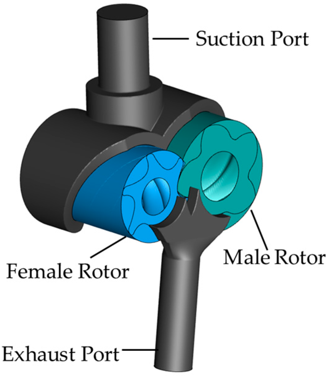
The rotor of the screw compressor is designed with a multi-arc asymmetric rotor profile, and the geometric parameters are outlined in Table 1. The compressor exhibits a theoretical displacement of 51.8 m3/h at 3000 rpm. The configuration of the suction and discharge ports is determined by the screw rotor profile and wrap angle, enabling the accommodation of diverse built-in volume ratios. The compressor’s theoretical profile, along with the arrangement of the suction and discharge ports, is provided in Figure 1.

Table 1.
The parameters of the twin-screw rotor profile.
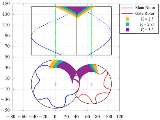
Figure 1.
The screw compressor profile and gas ports.
2.2. Component Structure and Size
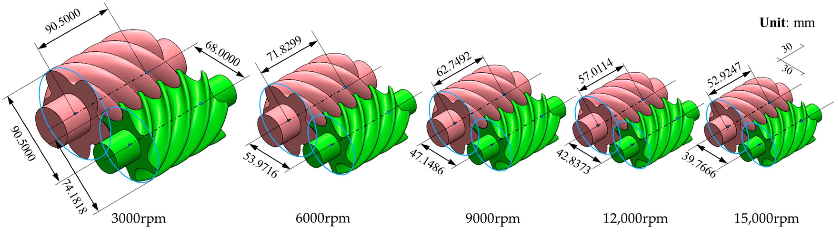
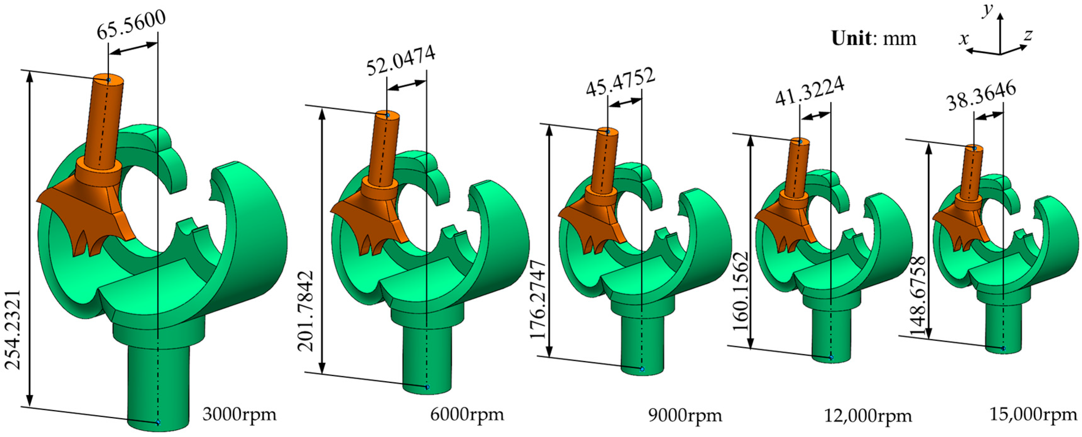
The screw rotor is optimized for high-speed operation while maintaining a constant theoretical capacity and built-in volume ratio in the compressor. The theoretical displacement demonstrates linear proportionality with the rotational speed, while exhibiting a cubic functional relationship with the rotor length. Table 2 presents a comparative analysis of screw rotor dimensions under constant displacement with varying rated operating conditions. As the rotational speed increases, the compressor’s geometric dimensions undergo a significant reduction, achieving enhanced compactness and a reduced weight. Notably, the length reduction rate demonstrates a diminishing trend with the increase in the rotational speed. Figure 2 presents a comparative analysis of rotor configurations maintaining equivalent theoretical displacements at 3000 rpm, 6000 rpm, 9000 rpm, 12,000 rpm, and 15,000 rpm. With an increasing rotational speed, the suction and discharge flow domains of the screw compressor exhibit a progressive reduction. Figure 3 provides a detailed representation of the specific variations in the suction and discharge flow domains at different rotational speeds.
Table 2.
Comparison of screw rotor structures with different rated speeds.

Figure 2.
The rotor structure at different rated speeds.
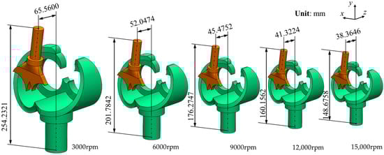
Figure 3.
The gas ports at different rated speeds.
3. Theoretical Model
The geometric and thermodynamic models of the screw compressor are systematically established. The geometric characteristics of the compressor are analyzed using a normalized methodology, while the power loss is evaluated through an exergy analysis model.
3.1. Geometric Property Model
The normalized working chamber volume serves as a critical evaluation criterion in assessing the geometric performance of screw compressors. This dimensionless parameter enables the systematic comparison of the volumetric efficiency across different compressor configurations, independently of absolute dimensional constraints.
To quantitatively assess the energy dissipation associated with suction and discharge processes in screw machinery, we assume that the total energy loss originates exclusively from the additional kinetic energy component within the flow field. The corresponding energy dissipation is determined by employing the following governing equation:
The differential relationship between the relative leakage quantity and the relative volumetric variation can be expressed through the following derivative formulation:
To quantitatively evaluate the exergy loss induced by leakage processes, an exergy analysis model is employed to assess the thermodynamic irreversibility associated with fluid leakage phenomena.
3.2. Thermodynamic Model
The dynamic model of the screw compressor working process is developed based on variable-mass thermodynamics, incorporating the following fundamental assumptions [17,18]:
- (1)
- Steady-state pressure conditions are present at the suction and discharge ports;
- (2)
- Complete thermal equilibrium exists between the refrigerant and lubricant;
- (3)
- The working fluid (gas) and lubricant (oil) remain single-phase states;
- (4)
- The gas within the working chamber maintains uniform temperature and pressure distributions;
- (5)
- Adiabatic boundary conditions are present at the chamber walls.
Figure 4 presents a schematic representation of the control volume configuration.
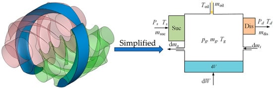
Figure 4.
The control volume of the screw compressor.
Based on the first law of thermodynamics and the established hypotheses, the governing energy equation for the control volume is derived as follows:
Mass conservation equation:
The numerical resolution of energy and mass conservation equations is bifurcated into two distinct formulations depending on the selection of the primary variables: the mass-specific internal energy (m-u) model and the pressure–temperature (p-T) model [19,20,21,22]. This study adopts the m-u model as the governing framework, with the pressure and temperature parameters subsequently derived through the post-processing of the converged solutions.
The leakage flow model employs the Lin two-phase nozzle model without considering the geometric boundary effects of leakage channels. For suction and discharge flows, a modified Lin two-phase nozzle model with upstream and downstream area corrections is implemented [23,24]. Thermodynamic properties are determined using the NIST REFPROP database, while the governing differential equations are numerically solved through the backward differentiation formula (BDF) method. The design condition parameters are specified in Table 3.
Table 3.
The parameters of the design condition.
The volumetric efficiency of the screw compressor:
The adiabatic efficiency of the screw compressor:
4. Numerical Model
4.1. Control Volume and Grids of the Fluid Domain
The CFD domain comprises the main and gate rotor fluid regions along with the suction and discharge ports. The numerical model incorporates critical geometric clearances, including the tip, interlobe meshing, and axial end clearances. Figure 5 illustrates the complete control volume configuration with detailed boundary definitions.

Figure 5.
Control volume of the fluid-domain screw compressor.
The fluid dynamics within the computational domain are governed by the fundamental conservation laws of mass, momentum, and energy. The turbulence characteristics are modeled using the shear stress transport (SST) k-ω formulation, which effectively combines the advantages of the k-ω model’s near-wall resolution with the k-ε model’s far-field performance. The total energy model is employed to simulate thermal energy transport, providing a comprehensive approach to accurate heat transfer prediction in high-speed compressible flows.
The thermodynamic properties of refrigerant R410A are determined using the Redlich–Kwong (RK) equation of state. The analysis assumes a negligible influence of the lubricating oil throughout the computational domain. The operational boundary conditions, including inlet/outlet pressure and temperature parameters, are specified in Table 3.
4.2. Independence Verification
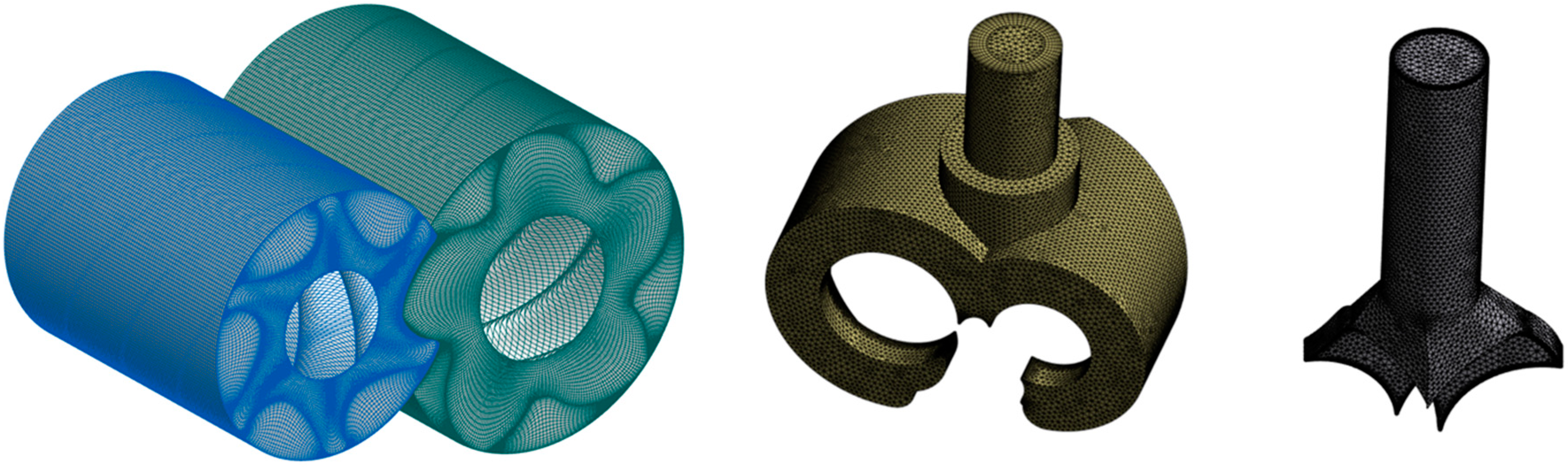
The stationary domain, which includes the suction and discharge ports, is meshed using ANSYS Meshing 2024R1 with tetrahedral-dominated elements, featuring boundary layer refinement and interface densification for improved accuracy. For the rotating domain, TwinMesh produces high-quality structured grids through a systematic process: first, a 2D cross-sectional mesh is created via node mapping between the screw rotor profile and casing contour, followed by the development of the 3D mesh through axial interpolation while maintaining rotational periodicity. This meshing approach guarantees optimal grid resolution for both stationary and rotating components. Figure 6 illustrates the detailed fluid-domain grid of the screw compressor. The computational study was conducted using ANSYS CFX 2024R1 to simulate the screw compressor model.
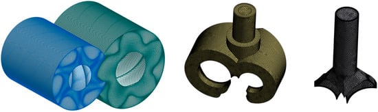
Figure 6.
Grids of the fluid domain for the screw compressor.
A grid independence study was conducted using the 3000 rpm rotor domain mesh. The investigation systematically varied the radial, circumferential, and axial node counts while monitoring changes in the intake mass flow rate and gas power output. The comparative results for different grid configurations are presented in Table 4. The analysis revealed that radial and axial node distributions exhibited a significant influence on the solution accuracy within the screw rotor domain. Based on the convergence criteria, Configuration 7 was selected as the optimal mesh configuration for the 3000 rpm rotor simulation. For the other rated rotor configurations, the mesh parameters were determined through geometric scaling based on the ratio of the cylinder diameter and rotor length relative to the 3000 rpm reference configuration.
Table 4.
Mesh independence verification for rotating flow domains.
The computational grids are generated using TwinMesh 2021, where the temporal resolution is intrinsically linked to the angular step size of the cross-sectional mesh. For the current simulation, an angular resolution of 1° is implemented, corresponding to the generation of a complete structured mesh and subsequent iterative computation at each degree of rotor rotation until the convergence criteria are satisfied. This 1° angular step size is consistently maintained across all rotor speed configurations to ensure temporal resolution uniformity.
5. Results and Analysis
5.1. The Efficiency of Different Rotors at the Rated Rotational Speed
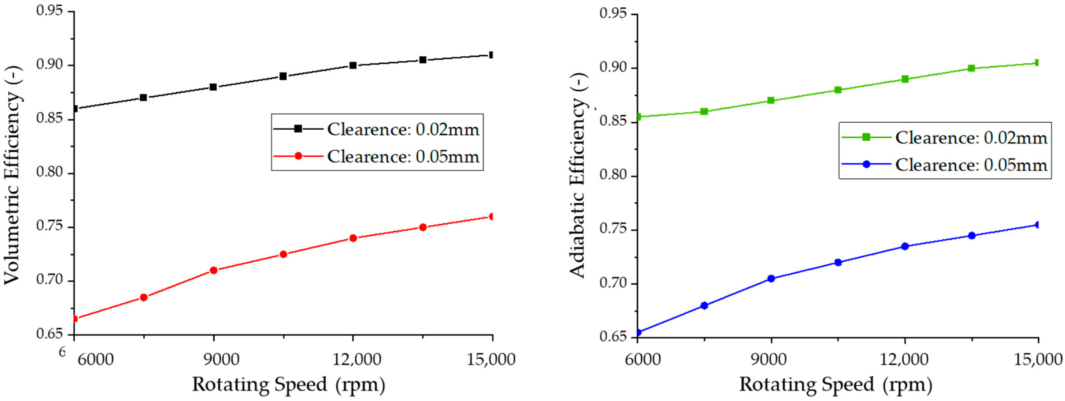
Figure 7 demonstrates the variation in the volumetric efficiency across different rated rotational speeds for the screw compressor. At lower speeds, the compressor exhibits reduced volumetric efficiency, which shows a significant improvement as the speed increases from low to high ranges. While the efficiency continues to rise into ultra-high speed regimes, the rate of increase diminishes considerably. Specifically, when the rotational speed is elevated from 6000 rpm to 9000 rpm, 12,000 rpm, and 15,000 rpm, the volumetric efficiency increases by 5.07%, 3.45%, and 1.33%, respectively, indicating a nonlinear relationship between the speed and efficiency. The adiabatic efficiency of different rotors exhibits a similar trend with an increasing rated rotational speed.
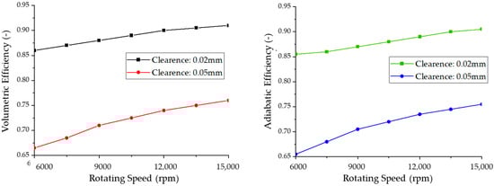
Figure 7.
The efficiency of the screw compressor at different clearances and different rated rotational speeds.
For screw rotors with identical displacement capacities, operating at ultra-high rotational speeds presents limited improvements in the volumetric and adiabatic efficiencies, while introducing significant challenges in rotor dynamics and operational stability. The clearance dimensions, which are intrinsically linked to the manufacturing precision and assembly tolerances, cannot be reduced without compromising the mechanical reliability.
5.2. The Gas Forces of Different Rotors at the Rated Rotational Speed
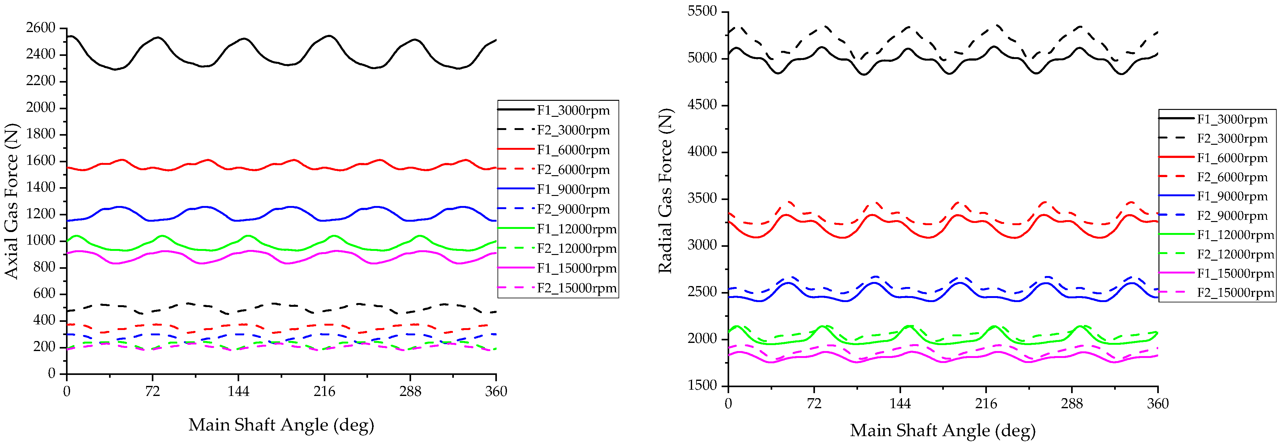
A CFD model was employed to analyze the gas forces acting on rotors with different rated speeds under identical operating conditions. Figure 8 illustrates the axial and radial gas forces exerted on each rotor configuration across various rotational speeds. The results demonstrate a significant reduction in both axial and radial gas forces with an increasing speed while maintaining a constant theoretical displacement. Notably, the main rotor experiences substantially higher axial forces compared to the gate rotor, whereas the gate rotor exhibits greater radial forces than the main rotor.
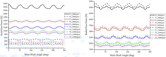
Figure 8.
Axial and radial gas forces on the main and gate rotors at different rated speeds.
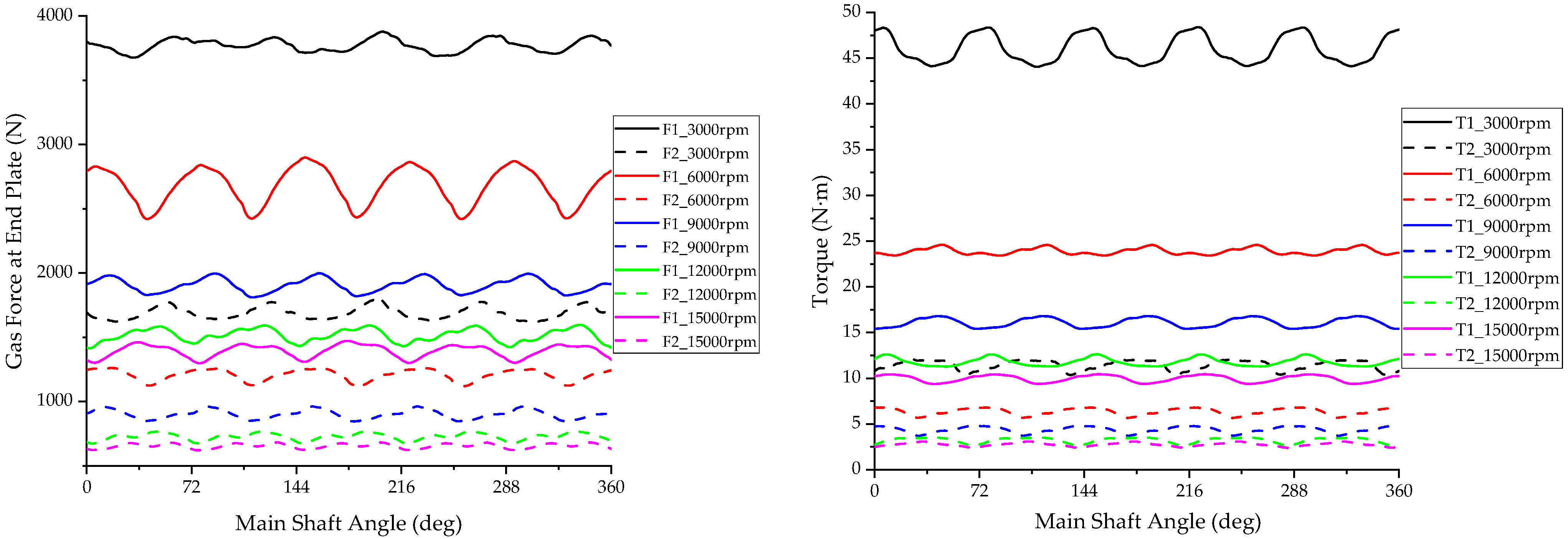
Figure 9 illustrates the variation in the end-plate gas forces and the resulting torque acting on the rotors. The analysis reveals that, with an increasing rated speed at constant displacement, the gas forces acting on the rotors decrease significantly. Notably, the main rotor experiences substantially higher axial gas forces compared to the gate rotor, necessitating differentiated bearing selection based on their distinct load characteristics. Concurrently, the torque demonstrates a marked reduction with increasing speed, accompanied by a decreased amplitude in the torque fluctuations.
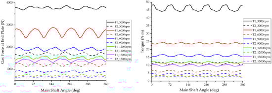
Figure 9.
The end-plate gas forces and torque on the main and gate rotors at different rated speeds.
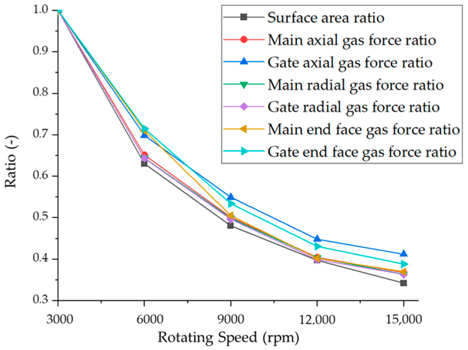
Using the axial, radial, and end-plate gas forces acting on the 3000 rpm rated rotor as reference values, the force ratios at other rotational speeds are compared relative to the 3000 rpm baseline (Figure 10). The analysis reveals that, with the exception of the gate rotor’s axial and end-plate gas forces, the force ratios exhibit consistent trends with the corresponding surface area ratios relative to the 3000 rpm configuration. This finding highlights the need for the special consideration of the force distribution on the gate rotor during the design process, particularly regarding its axial and end-plate loading characteristics.
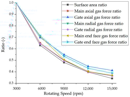
Figure 10.
Variations in rotor gas force ratios across different rotational speeds.
5.3. Leakage Characteristics of the High-Speed Compressor
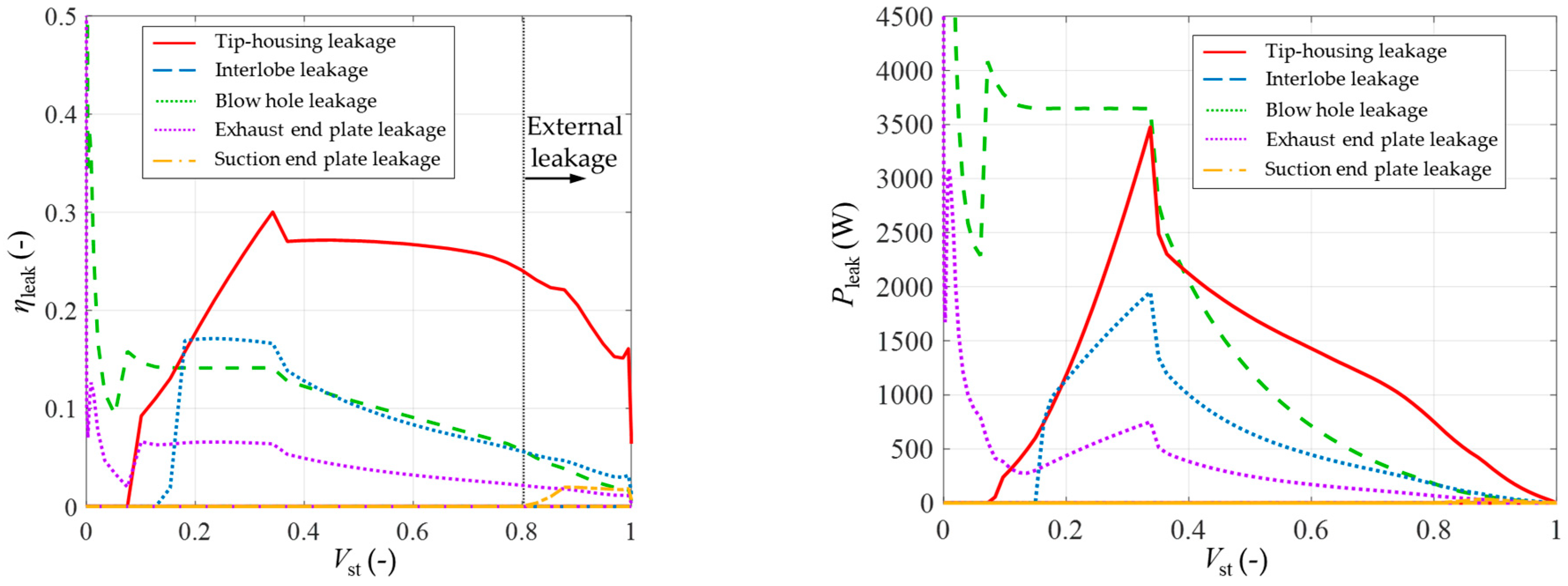
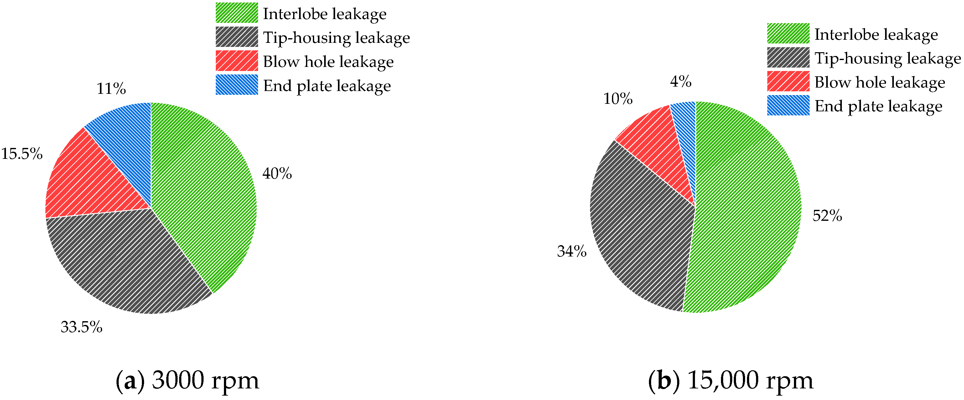
The investigated screw compressor configuration features a main rotor with five teeth, establishing 72° rotational periodicity. A leakage state transition occurs at 72° after suction completion, where the leakage mechanisms through both the tooth tip and triangular channels undergo a fundamental transformation from external to internal leakage. Figure 11 illustrates the leakage power loss and leakage rate characteristics of the screw compressor operating at 3000 rpm. The analysis reveals a distinct hierarchy of leakage flow magnitudes through various pathways under identical clearance conditions: tip-housing leakage (dominant), interlobe leakage (secondary), blow hole leakage (tertiary), exhaust end-plate leakage, and suction end-plate leakage (minimal).
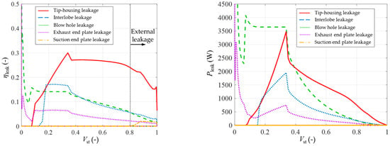
Figure 11.
The leakage rate and the power loss leakage flow rate of the screw compressor.
The energy loss hierarchy induced by the leakage pathways is established as follows: interlobe leakage (primary), tip-housing leakage (secondary), blow hole leakage, exhaust end-plate leakage, and suction end-plate leakage (minimal). The interlobe leakage exhibits greater energy loss than the tip-housing leakage due to its persistent external leakage. This results in higher pressure differentials, causing increased specific energy loss compared to the tip-housing leakage.
Figure 12 presents a comparative analysis of the leakage characteristics for rotors operating at different rated speeds while maintaining a constant displacement capacity. The results demonstrate that, despite the reduction in rotor dimensions with an increasing rotational speed, contact line leakage remains the dominant contributor to the overall leakage losses.
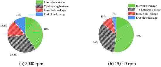
Figure 12.
Comparison of the leakage power loss for rotors with different rated speeds at constant displacement.
5.4. The Effects of the Rotor Configuration and Wrap Angle
The analysis demonstrates that leakage losses remain the predominant loss mechanism in high-speed small screw compressor design. While an increasing rotational speed can decrease leakages, this approach reduces the rotor stability and motor efficiency at elevated speeds. For compressors with identical external dimensions, leakage reduction strategies extend beyond clearance minimization to include decreasing the leakage path length through optimized rotor configurations. Specifically, reducing the number of rotor lobes improves the area utilization coefficient while decreasing the leakage proportion, thereby enhancing the overall performance.
Based on these principles, a 12,000 rpm rated speed was selected, and the rotor geometry was optimized to minimize the leakage area. This optimization resulted in a novel 4/5 lobe rotor profile. Under the conditions of a constant theoretical displacement and built-in volume ratio, Figure 13 illustrates the pressure variation with respect to the normalized volume for both the 4/5 and 5/6 lobe configurations at the design operating conditions. During the compression and discharge processes, the 4/5 lobe configuration demonstrates significantly reduced over-compression phenomena compared to the 5/6 lobe, accompanied by lower discharge pressure fluctuations. These characteristics contribute to enhanced energy efficiency and reduced power consumption.
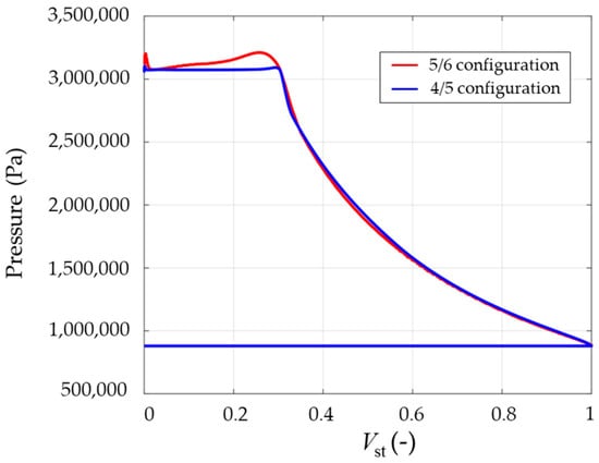
Figure 13.
Pressure variation with normalized volume for both 4/5 and 5/6 lobe configurations at design operating conditions.
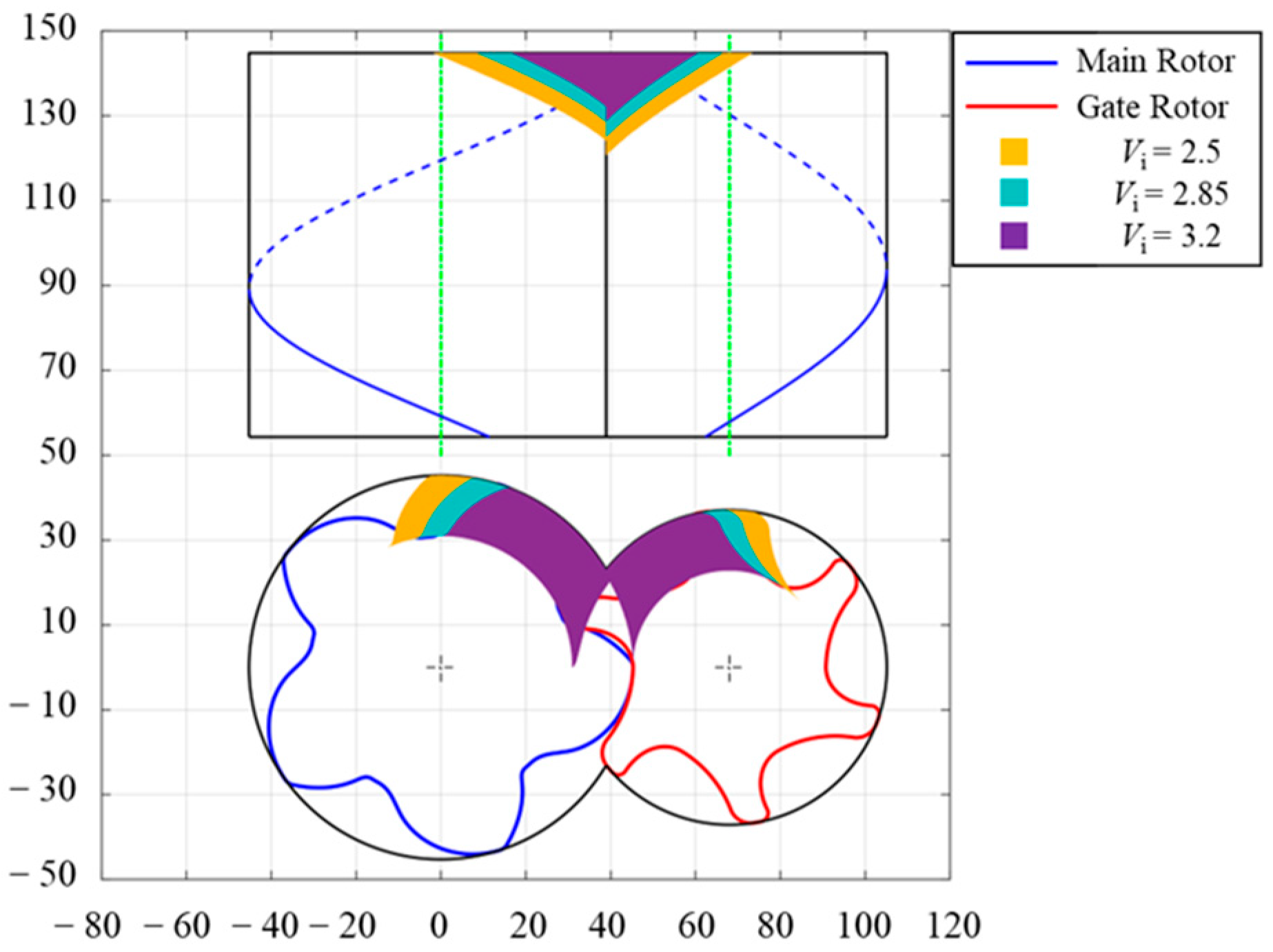
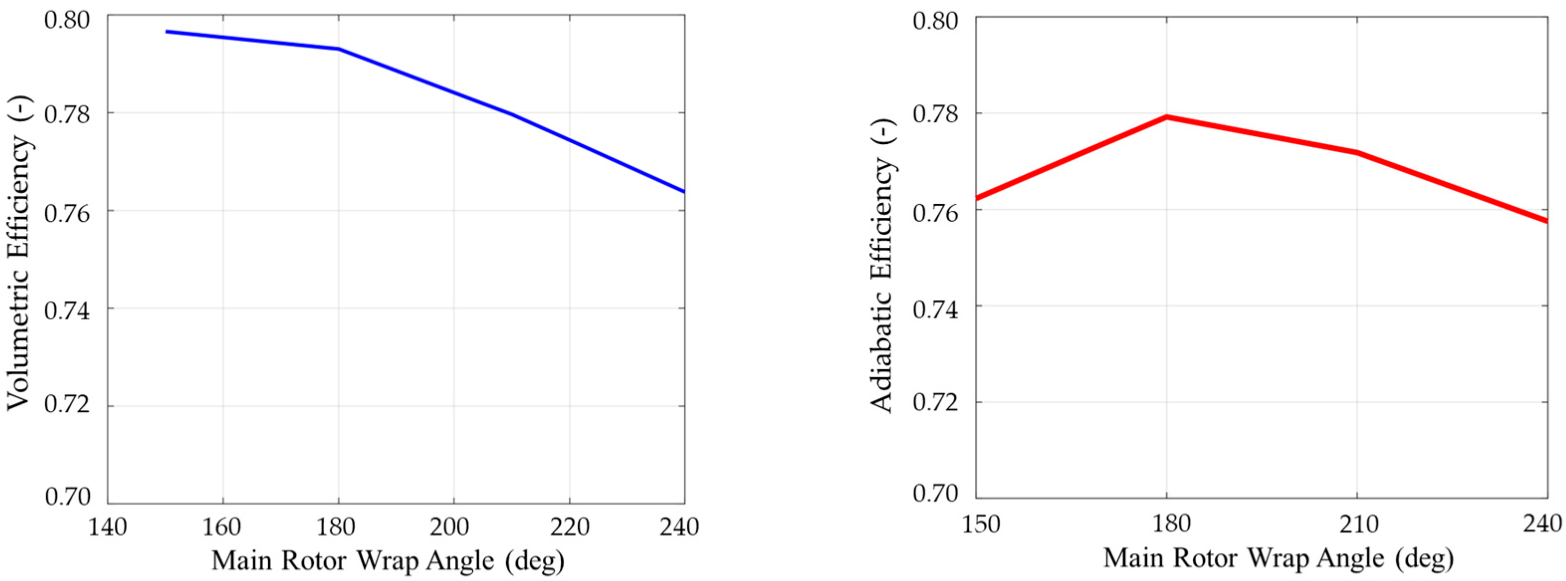
The variation in the wrap angle serves as an effective parameter for the optimization of the balance between leakage losses and discharge resistance. Figure 14 presents the discharge port configurations for screw rotors with different wrap angles at a constant built-in volume ratio of 2.8. Utilizing the thermodynamic performance prediction model, Figure 15 illustrates the impact of the wrap angle on the efficiency.
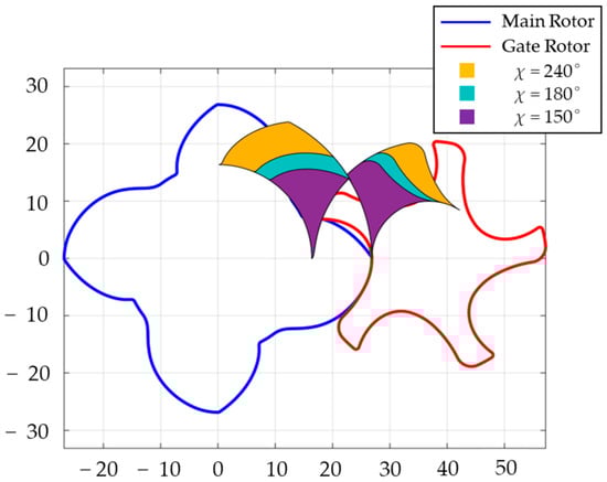
Figure 14.
The discharge port with different wrap angles at a constant built-in volume ratio.
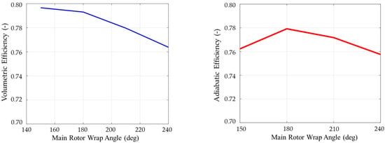
Figure 15.
The volumetric and adiabatic efficiencies of rotors with different wrap angles.
The analysis reveals that the volumetric efficiency decreases with an increasing wrap angle due to an extended contact line length. In contrast, the adiabatic efficiency demonstrates a non-monotonic relationship with the wrap angle. At lower wrap angles, the reduced discharge port area leads to increased discharge power losses. Conversely, higher wrap angles exhibit diminished discharge power losses but are accompanied by elevated leakage losses. This trade-off relationship results in an optimal wrap angle that maximizes the adiabatic efficiency by balancing these competing loss mechanisms. Figure 16 illustrates the variation in the power losses across different wrap angles, quantitatively demonstrating this efficiency optimization phenomenon.
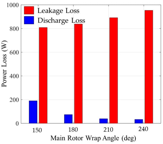
Figure 16.
Power losses of the rotor with different wrap angles.
6. Conclusions
This study investigated the high-speed miniaturization potential of refrigeration screw compressors by designing rotors with varying rated speeds at constant displacement. A comprehensive analysis framework was developed, integrating geometric characterization, thermodynamic modeling, and CFD-based force analysis. The performance characteristics under miniaturized high-speed conditions were systematically compared, leading to the following conclusions.
At constant rated speeds, reducing the leakage clearances significantly improves both the volumetric and adiabatic efficiencies. As the rated speed increases and the rotor dimensions decrease, the gas forces acting on the rotors decrease significantly, generally correlating with the reduction in the force-bearing areas. However, the gate rotor experiences higher-than-ideal axial and end-face gas forces. Under ultra-high-speed conditions, the efficiency gains from further speed increases become negligible.
While tooth tip leakage represents the largest volumetric leakage flow in screw compressors, contact line leakage contributes the most significantly to the power losses due to the huge pressure differential across the contact line. When the rated speed increases to 15,000 rpm, contact line leakage remains the dominant source of power loss, with its relative contribution showing a marked increase.
For screw compressors with identical cylinder dimensions, reducing the number of lobes increases the area utilization coefficient while enabling leakage reduction through optimized profile design. Larger wrap angles, at constant theoretical displacement and rotor profiles, extend the contact line length and increase the discharge port area, leading to reduced volumetric efficiency. This creates a trade-off between increased leakage losses and decreased discharge losses, resulting in an optimal wrap angle that maximizes the adiabatic efficiency.
This research on high-speed small screw compressors is a comprehensive study. However, this article only theoretically considers the influence of the structural parameters of high-speed miniaturized rotors on their performance. In addition to theoretical design, the selection of high-temperature-resistant and high-strength materials for rotors, rotor dynamic balance and thermal deformation, aerodynamic noise caused by high speeds, cooling, and lubrication are all directions for subsequent research.
Author Contributions
Conceptualization, X.W. and Z.H.; methodology, K.M. and D.L.; software, K.M.; validation, K.M. and X.W.; formal analysis, H.L.; investigation, H.L.; resources, X.W.; data curation, K.M.; writing—original draft preparation, K.M.; writing—review and editing, K.M.; visualization, K.M.; supervision, H.L. and Z.H.; project administration, Z.H.; funding acquisition, X.W. and H.L. All authors have read and agreed to the published version of the manuscript.
Funding
The project was supported by the National Key Research and Development Program of China (Project No. 2024YFB4007403).
Institutional Review Board Statement
Not applicable.
Informed Consent Statement
Not applicable.
Data Availability Statement
The original contributions presented in the study are included in the article, further inquiries can be directed to the corresponding author.
Conflicts of Interest
Authors Xiaokun Wu and Huaican Liu were employed by the company Gree Electric Appliances Inc. The remaining authors declare that the research was conducted in the absence of any commercial or financial relationships that could be construed as a potential conflict of interest.
Nomenclature
| Inlet enthalpy | |
| Outlet enthalpy | |
| Mass flow | |
| Actual intake mass flow rate | |
| Inlet flow rate | |
| Leakage mass flow rate | |
| Outlet flow rate | |
| Intake mass flow rate | |
| Theoretical intake mass flow rate | |
| Pressure | |
| Pressure of high-pressure chamber | |
| Pressure of low-pressure chamber | |
| Time | |
| Internal energy | |
| Velocity | |
| Inlet velocity | |
| Outlet velocity | |
| Exergy | |
| Indicated power | |
| Power loss | |
| Heat quantity | |
| Temperature of high-pressure chamber | |
| Temperature of low-pressure chamber | |
| Working chamber volume | |
| Bulit-in volume ratio | |
| Normalized working chamber volume | |
| Volume of the working chamber at the end of suction | |
| Adiabatic efficiency | |
| Dimensionless leakage mass flow ratio | |
| Volumetric efficiency | |
| Density | |
| Angular velocity | |
| Main shaft angle | |
| Enthalpy difference |
References
- Abdan, S.; Stosic, N.; Kovacevic, A.; Smith, I.; Asati, N. Oil drag loss in oil-flooded, twin-screw compressors. Proceedings of the Institution of Mechanical Engineers. Part E J. Process Mech. Eng. 2023, 237, 1137–1144. [Google Scholar] [CrossRef]
- Wang, C.; Wang, B.; Liu, M.; Xing, Z. A review of recent research and application progress in screw machines. Machines 2022, 10, 62. [Google Scholar] [CrossRef]
- Patil, S.; Abdan, S.; Asati, N.; Stosic, N.; Kovacevic, A. Improvement of Screw Compressor Performance by Rotor Profile Modification to Reduce Mechanical Losses. In Proceedings of the ASME International Mechanical Engineering Congress and Exposition, New Orleans, LA, USA, 29 October–2 November 2023. [Google Scholar]
- Matuzović, M.; Rane, S.; Patel, B.; Kovačević, A.; Tuković, Ž. Analysis of conjugate heat transfer in a roots blower and validation with infrared thermography. Int. J. Thermofluids 2022, 16, 100234. [Google Scholar]
- Yang, J.; Xu, M.; Lu, Z. Design of Twin-Screw Compressor Rotor Tooth Profile with Meshing Clearance Based on Graphic Method and Alpha Shape Algorithm. J. Shanghai Jiaotong Univ. (Sci.) 2023, 28, 243–254. [Google Scholar]
- Wu, H.; Liang, M.; Chen, S.; Wu, G.; Huang, H.; Xu, S.; Xing, Z. Research on thermal deformation and clearances of oil-free twin screw compressor under cryogenic conditions. Proc. Inst. Mech. Eng. Part E J. Process Mech. Eng. 2024. [Google Scholar] [CrossRef]
- Rane, S.; Kovačević, A.; Stošić, N.; Smith, I.K. Bi-directional system coupling for conjugate heat transfer and variable leakage Gap CFD analysis of twin-screw compressors. In Proceedings of the IOP Conference Series: Materials Science and Engineering, London, UK, 6–9 September 2021. [Google Scholar]
- Petrescu, V.; Tomescu, S.; Vasile, E.; Stănescu, T.; Slujitoru, C. The Influence of Clearances on Energy Efficiency in Screw Compressors. In Proceedings of the 11th International Conference on ENERGY and ENVIRONMENT (CIEM), Bucharest, Romania, 26–27 October 2023. [Google Scholar]
- Willie, J.; Sachs, R. Structural and torsional vibration and noise analysis of a dry screw compressor. Proc. Inst. Mech. Eng. Part E J. Process Mech. Eng. 2017, 23, 4–13. [Google Scholar]
- Wu, Y.R.; Tran, V.T. Dynamic response prediction of a twin-screw compressor with gas-induced cyclic loads based on multi-body dynamics. Int. J. Refrig. 2016, 65, 111–128. [Google Scholar]
- Abdan, S.; Patil, S.; Stosic, N.; Kovacevic, A.; Smith, I. Experimental validation of the screw compressor oil drag model for various rotor profiles. Proc. Inst. Mech. Eng. Part E J. Process Mech. Eng. 2024, 238, 2740–2749. [Google Scholar]
- Wu, X.; Xing, Z.; Chen, W.; Wang, X. Performance investigation of a pressure pulsation dampener applied in the discharge chamber of a twin screw refrigeration compressor. Int. J. Refrig. 2018, 85, 70–84. [Google Scholar] [CrossRef]
- Zhou, M.; Chen, W.; He, Z.; Xing, Z. Research on control techniques of vibration and noise in twin screw refrigeration compressor. Refrig. Air-Cond. 2019, 19, 55–60. [Google Scholar]
- Yang, S.; Ouyang, W.; Wang, L.; Yu, Z. Experimental investigation of sound reduction for twin-screw compressor based on oil supply optimization. Fluid Mach. 2021, 49, 7–13. [Google Scholar]
- Liu, M.; Wang, C.; Li, Y.; Li, Y.; Liu, L.; Xing, Z. Experimental Investigation on the Effect of Water Cooling on a Dry Twin-Screw Air Compressor for Proton Exchange Membrane Fuel Cells. Appl. Sci. 2024, 14, 2537. [Google Scholar] [CrossRef]
- Wagner, J.; Markham, D. Design of a compact, lightweight screw-type compressor for refrigeration systems. In Proceedings of the 15th IEEE Intersociety Conference on Thermal and Thermomechanical Phenomena in Electronic Systems (ITherm), Las Vegas, NV, USA, 31 May–3 June 2016. [Google Scholar]
- Xing, Z. Screw Compressors: Theory, Design, and Application, 1st ed.; China Machine Press: Beijing, China, 2000; pp. 118–125. (In Chinese) [Google Scholar]
- Stosic, N.; Smith, I.; Kovacevic, A. Screw Compressors: Mathematical Modelling and Performance Calculation, 1st ed.; Springer Science & Business Media: Berlin, Germany, 2005; pp. 49–59. [Google Scholar]
- Liu, G.; Yang, Q.; Zhao, Y.; Wang, L.; Li, L. Analysis of performance of two-stage screw compressor under various operating conditions. Proc. Inst. Mech. Eng. Part A J. Power Energy 2016, 23, 660–668. [Google Scholar]
- Ziviani, D.; Bell, I.; Zhang, X.; Lemort, V.; Paepe, M.; Braun, J.; Groll, E. PDSim: Demonstrating the capabilities of an open-source simulation framework for positive displacement compressors and expanders. Int. J. Refrig. 2020, 110, 323–339. [Google Scholar]
- Höckenkamp, S.; Grieb, M.; Utri, M.; Brümmer, A. Performance Analysis of a Water-Injected Twin-Screw Compressor in a High-Temperature R718 Heat Pump. In Proceedings of the IOP Conference Series: Materials Science and Engineering, Dortmund, Germany, 3–5 September 2024. [Google Scholar]
- Stosic, N. On heat transfer in screw compressors. Int. J. Heat Fluid Flow 2015, 51, 285–297. [Google Scholar] [CrossRef]
- Wang, C.; Xing, Z.; Chen, W.; Sun, S.; He, Z. Analysis of the leakage in a water-lubricated twin-screw air compressor. Appl. Therm. Eng. 2019, 155, 217–225. [Google Scholar] [CrossRef]
- Cao, F.; Gao, T.; Li, S.; Xing, Z.; Shu, P. Experimental analysis of pressure distribution in a twin screw compressor for multiphase duties. Exp. Therm. Fluid Sci. 2011, 35, 219–225. [Google Scholar]


Disclaimer/Publisher’s Note: The statements, opinions and data contained in all publications are solely those of the individual author(s) and contributor(s) and not of MDPI and/or the editor(s). MDPI and/or the editor(s) disclaim responsibility for any injury to people or property resulting from any ideas, methods, instructions or products referred to in the content. |
© 2025 by the authors. Licensee MDPI, Basel, Switzerland. This article is an open access article distributed under the terms and conditions of the Creative Commons Attribution (CC BY) license (https://creativecommons.org/licenses/by/4.0/).