Article

Deflection Modeling and Curvature Manipulation of a Variable-Stiffness Flexible Needle

School of Mechanical and Electronic Engineering, Shandong Jianzhu University, Jinan 250101, China
*
Author to whom correspondence should be addressed.
Appl. Sci. 2025, 15(7), 3746; https://doi.org/10.3390/app15073746
Submission received: 22 February 2025 / Revised: 20 March 2025 / Accepted: 27 March 2025 / Published: 28 March 2025

Abstract

:
To address the need for improving the flexibility of flexible needles, a technique that achieves needle steering by altering the needle’s stiffness is proposed. Needle tip forces were simplified, and a deflection model was then developed based on the Timoshenko beam theory. By combining theory and simulation, the influences of the stylet diameter, extension length, and tip direction on needle bending were analyzed. The deflection of the flexible needle is proportional to the cube of the stylet extension length. The needle with a 0.4 mm stylet diameter and an 8 mm extension length produces 8.841 mm more deflection than conventional flexible needles. The extension length can effectively regulate the bending curvature of the flexible needle, thus improving the flexibility of the puncture to some extent.

1. Introduction

The percutaneous puncture has extremely important clinical applications in the diagnosis and treatment of lesions, including tissue biopsy, ablation, and radiotherapy, among others. The effectiveness of these procedures depends on the accuracy of needle placement with minimal damage to the surrounding tissue, which is compromised by instrument design limitations [1,2]. During liver biopsy procedures, the intricate vascular architecture (e.g., hepatic veins, tertiary portal vein branches, and biliary tree) poses significant challenges to percutaneous needle navigation. Needle steering techniques overcome these limitations by enabling preoperative trajectory optimization, which expands accessible puncture pathways and reducing iatrogenic injury risks [3,4,5]. Furthermore, respiratory motion and tissue deformation cause organ displacement, necessitating dynamic trajectory adjustments [6]. Curvature-adjustable needle systems allow real-time compensation for tissue displacement, thereby ensuring precise lesion targeting.
Initial research on needle steering was performed on conventional flexible bevel-tip needles, also known as passive needles [7,8]. Needle deflection due to tip asymmetry can be used to avoid sensitive areas such as blood vessels and nerves and can flexibly reach lesions that are difficult for traditional rigid needles. In recent years, an increasing number of researchers have focused on active steering mechanisms to enhance device maneuverability in percutaneous interventions [3,4]. The structure of the active needle can be altered by an external driving force, thus actively steering the puncture trajectory, which provides an effective method to improve the puncture flexibility and enhance the deviation correction ability.
The active needles designed for steering can be categorized as follows: precurved stylets, programmable bevel needles, tendon-actuated needles, shape memory alloy (SMA)-actuated needles, and magnetically driven flexible needles. The four-probe programmable bevel steerable needle proposed by Favaro et al. [9,10] is inspired by the ovipositor of the wood wasp, and these four probes can be freely extended and retracted through an interlocking mechanism. The relative motion of the probes was used to change the steering of the flexible needles, and the offset length was used to adjust the bending curvature. In addition, they optimized the cross-sectional geometries of the catheter and employed thermal drawing technology to produce a new prototype with a diameter of 1.3 mm and a radius of curvature of 109.113 mm. Deaton et al. [11,12] designed a tendon-driven omni-directional steerable stylet that was fabricated by micromachining a superelastic nitinol tube with an outer diameter of 1.17 mm and a wall thickness of 0.1 mm. With a maximum bending angle of 20°, the steerable stylet is actuated by two nitinol tendons arranged at 180°. Similarly, Zhang et al. [13] developed a flexible biopsy robot consisting of a tendon-driven catheter and an inner sliding flexible needle as well as their driving systems. The 4-degree-of-freedom catheter has a maximum bend of 140° and a positioning accuracy of 0.72 mm. The internal structure and constitution of the tendon-driven needles are usually complex due to the use of tendon wires or rods [14]. Padasdao et al. [15] combined several soft and solid tubes to form an actively bending surgical needle and drove three 120° distributed SMA wires to realize deflection in all directions. The wires are looped at the needle tip, providing double bending force for the needle and facilitating electrical connections at the bottom end of the needle. Yan et al. [16] developed a percutaneous robot that features a flexible wrist made of an SMA spring. At low temperature, the SMA behaves like a spring backbone that allows the needle to bend under tendon traction (up to 90°), thus minimizing the risk of cardiac perforation. In contrast, when heated, the SMA stiffens, allowing insertion into the pericardium for drainage. SMAs typically require a longer heating time to reach the phase transition temperature, which increases the puncture time. Bui et al. [17,18,19] proposed a curvature-controllable steerable needle consisting of two parts: a cannula and a bevel-tipped stylet. The curvature of the needle’s path is controlled by the offset between the bevel tip and cannula. Gelatin puncture experiments revealed a linear relationship between the curvature and the offset. They then conducted trajectory prediction and fuzzy control studies based on a kinematic model. However, analysis of the possible forces and factors that may be involved in the deflection mechanism seems to have been put on hold and is not clear.
In this paper, a deflection model for a stiffness-tunable flexible needle under external force is established, and the method for manipulating the curvature is clarified. Two additional variable-stiffness needle structures are proposed and analyzed comparatively to evaluate cross-section effects on deflection. Then, simulation and puncture validation experiments are conducted to investigate the effects of puncture speed and flexible needle stiffness on bending curvature.

2. Materials and Methods

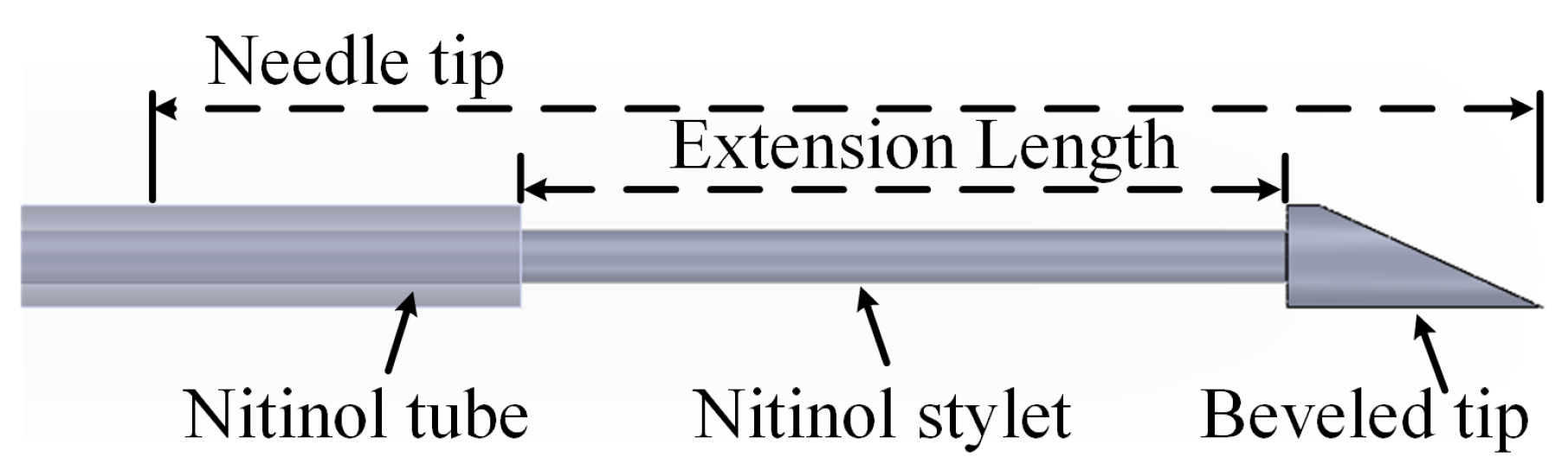
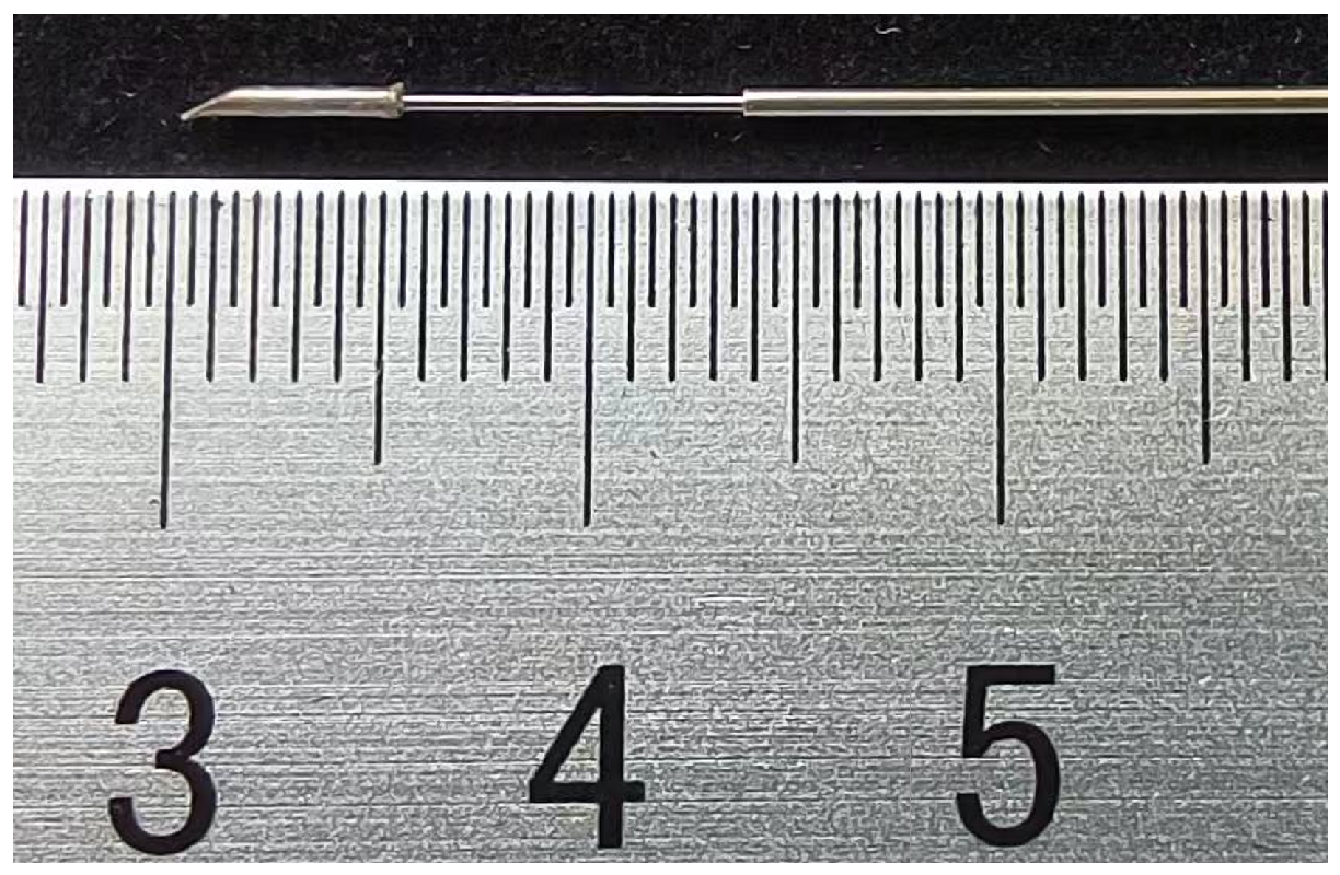
2.1. Design of the Stiffness-Tunable Needle

The conventional flexible needle tip is deflected under external forces and moments in the radial direction, with the bending behavior being related to the geometry of the needle [20,21,22]:
  • Within certain limits, a thicker tip on the flexible needle results in greater extrusion deformation of the soft tissue after cutting. That means a greater deflection force, which the soft tissue can provide.
  • A sharper flexible needle tip with a larger bevel will displace more tissue and generate a greater reaction force on the tip.
  • If the body of the needle is too stiff or too thin, or if the tissue is unable to support the traversal of the body, it can slice through the tissue.
The body of a flexible needle with appropriate structural parameters will follow the movement of the needle tip during puncture. Thus, by adjusting the stiffness of the needle tip, the bending radius of the flexible needle can be manipulated. The flexible needle with variable stiffness proposed by Bui et al. [17] is shown in Figure 1.
The stiffness-tunable flexible needle consists of two parts: a nitinol stylet with a variable diameter and a supporting nitinol tube. Specifically, the tip of the flexible needle features a conventional beveled design with a diameter matching the outer diameter of the nitinol tube, allowing it to compress the tissue fully and provide sufficient deflection force. Compared to the beveled tip, the diameter of the stylet is slightly thinner (not limited to the cylindrical structure shown in Figure 1 or the axial position) and is comparable to the inner diameter of the tube.
The thinner stylet results in a smaller bending moment, making it easier for the flexible needle to produce a larger deflection when the tip is subjected to a constant cutting force.
A variable-stiffness needle is a retractable cannula device in which the stiffness can be dynamically adjusted during tissue insertion. In order to increase the bending curvature of the needle, the stiffness of the needle tip (actually a portion of the stylet and the tube) is reduced by retracting the nitinol tube (i.e., increasing the stylet extension length). Conversely, advancing the nitinol tube (i.e., shortening the stylet extension) increases the stiffness and thereby reduces the curvature. When the stylet extension length is zero, the variable-stiffness flexible needle essentially becomes a conventional bevel-tip needle.

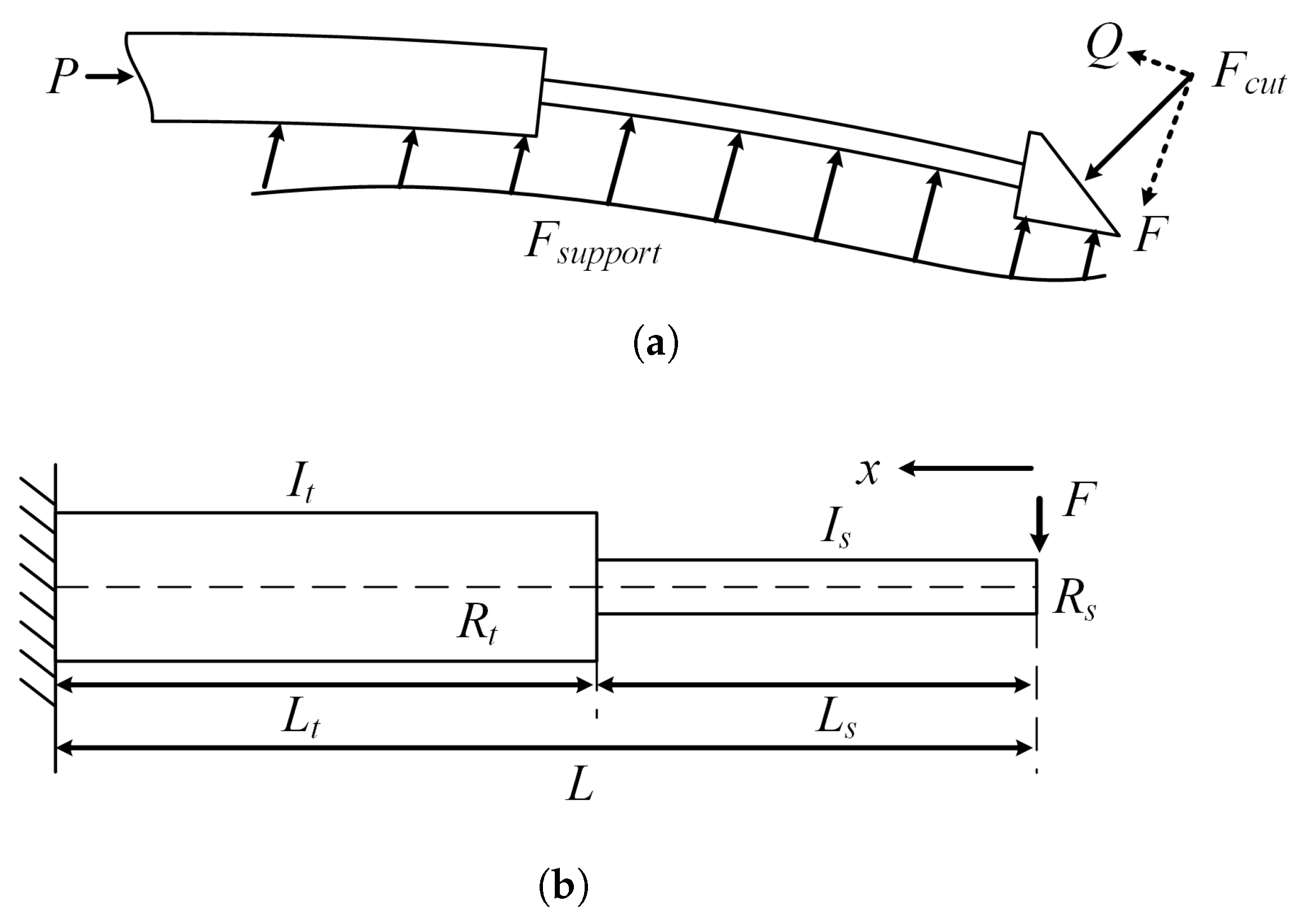
2.2. Model Analysis of Flexible Needle

Similarly to a normal bevel-tip needle, a stiffness-tunable needle interacts with the surrounding tissue when inserted into soft tissue, as shown in Figure 2a. The needle is inserted into the soft tissue with an external insertion force P. As the needle is inserted, a shearing force, or cutting force F c u t , is applied to the needle in a direction perpendicular to the beveled tip. The transverse and axial components of F c u t are F and Q, respectively. The soft tissues are deformed and compressed, imparting a supporting force F s u p p o r t to the needle.
Studies have shown that the deflection of a long, flexible, bevel-tip needle can be approximated by modeling it as a cantilever beam during insertion into soft tissue [17,23]. Before analyzing the deflection, the following notes and explanations are provided:
  • The beveled tip is designed to generate an asymmetric deflection force. In fact, it is possible to make the beveled tip very short without compromising the deflection force. Compared to the needle tip, which is several centimeters long, the beveled tip is relatively short (as short as 3 mm), and its effect on beam deflection is negligible.
  • The variable-stiffness needle bends because the extending stylet adjusts the deflection of the needle, not because the beveled tip bends directly. The bending deformation of the beveled tip is minimal. Consequently, the beveled tip can be ignored when modeling the physics of the variable-stiffness needle.
  • The cutting force F c u t is an equivalent force applied to the beveled tip. For uniform tissue, the cutting force is essentially constant during puncture, while for non-uniform tissue, this force varies. Based on the quasi-static assumption, a linear superposition can be applied to estimate the deflection estimation under a changing force.
  • From our previous puncture force studies [24] and others’ puncture force simulations [25], it is clear that although bending occurs in the puncture, the cutting force is essentially constant in uniform tissue. The deformation of the beveled tip during puncture is so small that it can be neglected, and thus the partial forces F and Q are also essentially constant. The transverse force F is the key factor affecting deflection, while the axial force Q, transmitted through the stylet to the base of the needle, affects the insertion force.
Consequently, the needle tip can be ignored when modeling the physics of the variable-stiffness needle. The deflection model can be simplified to a cantilever beam model subjected to a transverse force F, as illustrated in Figure 2b.
The right part of the needle tip consists of the protruding stylet, while the left part is the supporting tube. The interior of the tube is filled with the stylet, and both parts are solid cylinders. The moments of inertia can be expressed as
I s = π R s 4 4
I t = π R t 4 4
where I s and I t are the moments of inertia of the stylet and tube, and R s and R t are the radii of the stylet and tube.
The shear stiffnesses can be expressed as
K s = π R s 2 G κ
K t = π R t 2 G κ
where K s and K t are the shear stiffnesses of the stylet and tube, G is the shear modulus, and κ is the shear correction factor.
In Timoshenko beam theory, the bending deflection is caused by the bending moments. The tip length is L = L s + L t , where L s is the stylet extension length and L t is the tube length. The bending moment at position x ( 0 x L ) from the right side can be denoted as
M = F x , 0 x L
Using Mohr’s integral method, the expression for the bending moment is
w b = 0 L M ( x ) M ( x ) ˜ E I ( x ) d x , 0 x L
where E is the Young’s modulus and M ( x ) ˜ is the bending moment under a virtual unit load (identical to M ( x ) , i.e., M ( x ) = x ˜ ).
In the right segment, there is
0 L s F x · x E I s d x = F L s 3 3 E I s , 0 x < L s
In the left segment, there is
L s L F x · x E I t d x = F ( L 3 L s 3 ) 3 E I t , L s < x L
Then, the total bending deflection (at the position x = 0 ) can be denoted as
w b = F L 3 3 E I t + F L s 3 3 E 1 I s 1 I t
In Timoshenko theory, the shear deflection is calculated as
w s = 0 L κ · V ( x ) · V ( x ) ˜ G A ( x ) d x , 0 x L
where V ( x ) = F is the actual shear force, V ( x ) ˜ = 1 is the virtual unit shear force, and A ( x ) is the cross-sectional area.
In the right segment, there is
0 L s κ F G A s d x = κ F L s G A s , 0 x < L s
In the left segment, there is
L s L κ F G A t d x = κ F L t G A t , L s < x L
The total shear deflection is
w s = κ F G L s A s + L t A t
The total deflection at the position x = 0 is the sum of the bending and shear contributions:
w ( 0 ) = w b + w s = F L 3 3 E I t + F L s 3 3 E 1 I s 1 I t + κ F G L s A s + L t A t
To identify the primary factors influencing deflection, the bending deflection, shear deflection, total deflection, and ratio of bending deflection to total deflection at different stylet extension lengths were calculated. To ensure consistency with subsequent simulations, the following parameters were used: F = 0.3 cos ( p i / 6 ) N ,   ν = 0.3 ,   E = 75 , 000 MPa ,   G = 2 ( 1 + ν ) / E ,   κ = 6 ( 1 + ν ) / ( 7 + 6 ν ) ,   R s = 0.2 mm , R t = 0.4 mm ,   L = 50 mm . The results are shown in Table 1.
As shown in Table 1, the bending deflection dominates the total deflection, accounting for over 99.98%. For slender beams, such as flexible needles, shear deformation can be safely neglected. Therefore, the deflection of the flexible needle in Equation (14) can be simplified to
w ( 0 ) = F L 3 3 E I t + F L s 3 3 E 1 I s 1 I t
where F L 3 / 3 E I t represents the deflection of a uniform beam under an external force F, i.e., the deflection of the conventional flexible needle with a beveled tip. The term ( F L s 3 / 3 E ) · ( 1 / I s 1 / I t ) shows the effect of the variable stiffness structure on the deflection. Since the radius of the stylet is smaller than that of the tube, I s < I t , we have ( F L s 3 / 3 E ) · ( 1 / I s 1 / I t ) > 0 , which indicates that the needle deflection increases. The smaller the moment of inertia of the stylet is, the easier it is for the flexible needle to bend; the longer the stylet extends out of the tube, the more significant the bending of the flexible needle becomes.
Since the diameters of the stylet and the tube are determined during the needle manufacturing process, the control strategy for the variable-stiffness flexible needle could be as follows: by controlling the length of the stylet protruding from the tube, the stiffness of the needle tip is adjusted, which in turn changes the bending curvature of the needle.

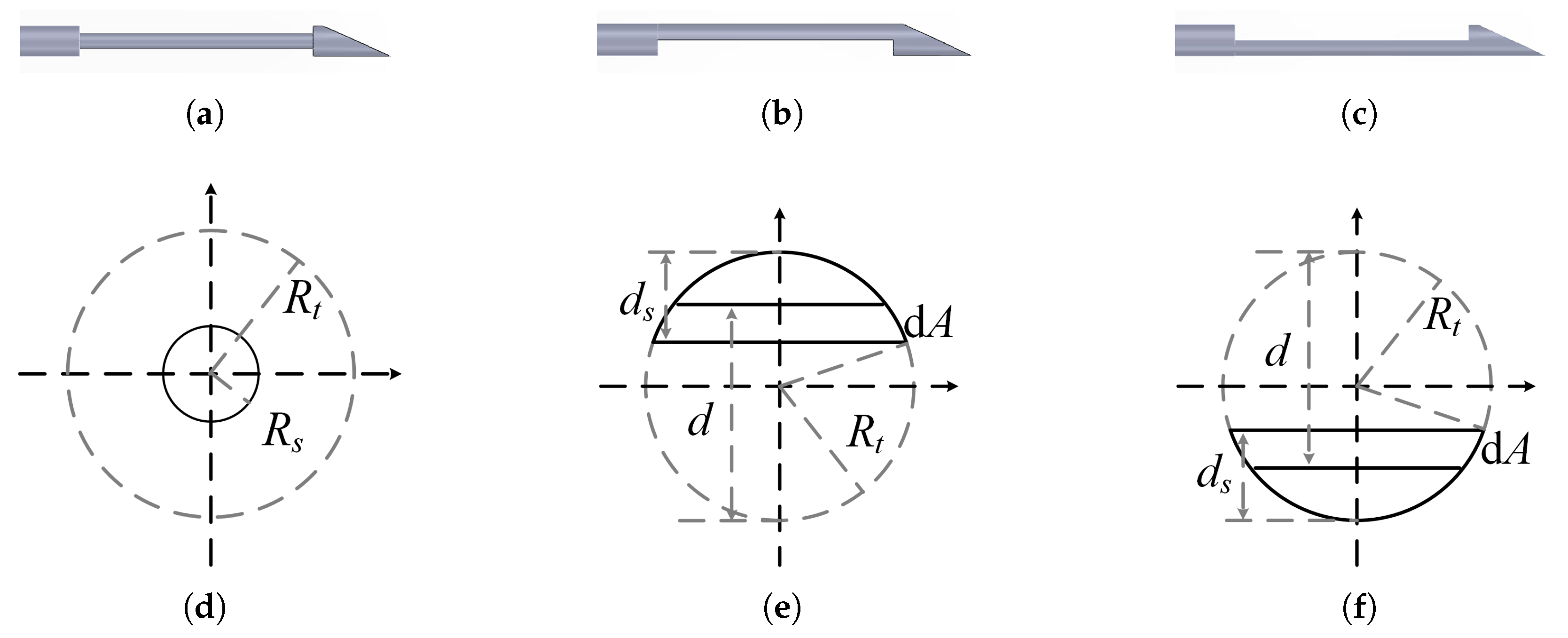
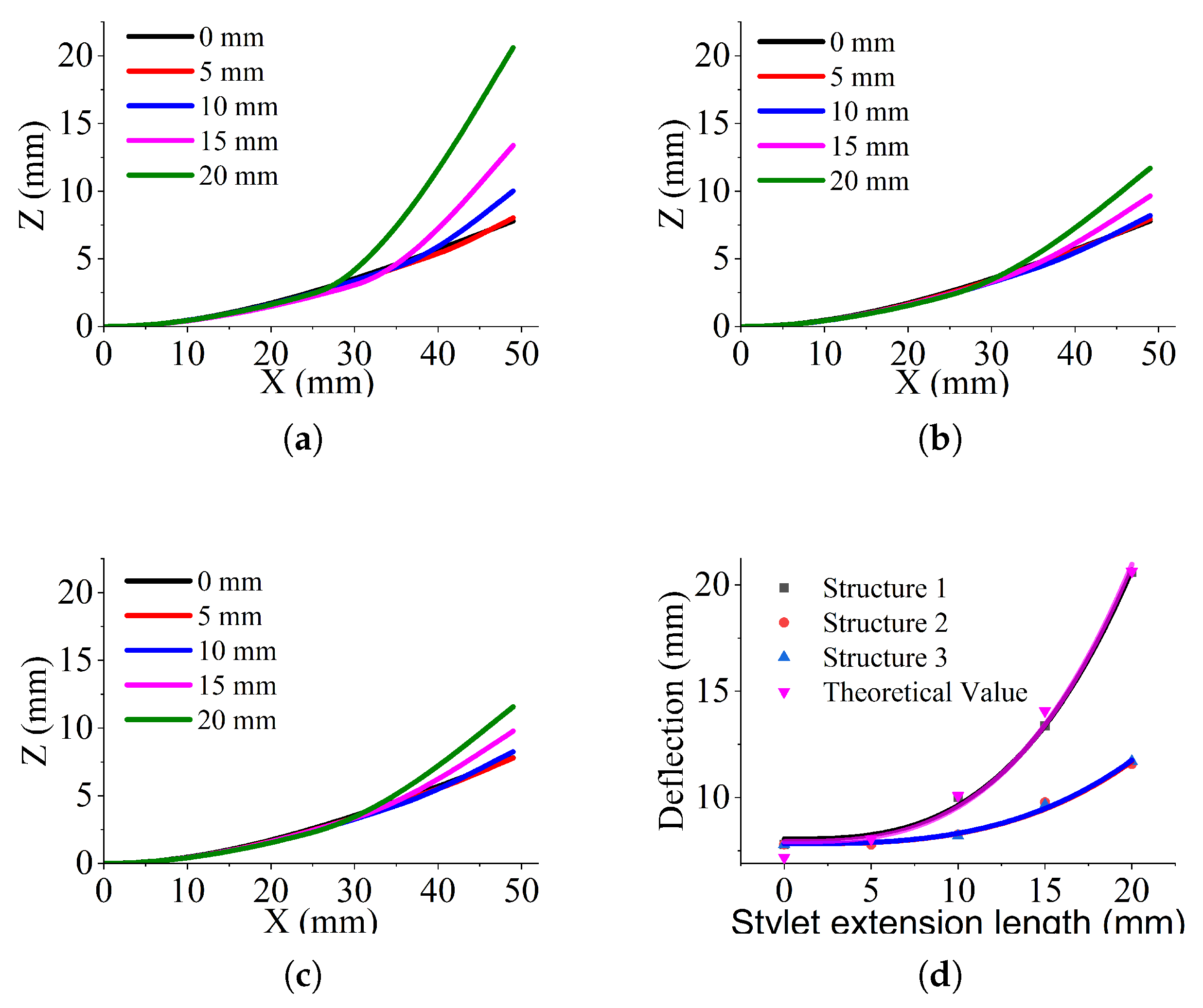
2.3. Simulation of the Effect of Stylet Diameter on Deflection

In addition to the structure shown in Figure 1 (noted as Structure 1), two other structures were designed, noted as Structure 2 and Structure 3, as shown in Figure 3a–c.
Unlike Structure 1, Structure 2 and Structure 3 have incomplete circles in the cross section of the stylet. The difference between Structure 2 and Structure 3 lies in the direction of the beveled tip. The effect of the stylet’s cross-sectional shape on the bending was investigated by comparing Structures 1 and 2. In order to eliminate the influence of the needle tip bevel in Structure 1 and Structure 2, Structure 3 was used to analyze whether the direction of the bevel affects the bending behavior of Structure 2.
The structural models of three needles were created in ANSYS WORKBENCH 2022R2, and a constant compressive load was applied to the tip bevel to analyze the effects of stylet length and thickness (the thickness of the remaining material) on the pure bending of flexible needles. The material properties [26], geometries, and loads are detailed in Table 2.
A structural model with a stylet diameter of 0.6 mm and a stylet length of 20 mm was created in ANSYS WORKBENCH 2022R2, as shown in Figure 4a. The automated meshing method was used, creating 1989 nodes and 846 elements. A fixed support was applied to the left side of the needle, and a vertical force of 0.3 N [24] was applied to the beveled tip. A path from (0, 0, 0) to (49, 0, 0) was created to obtain the deformations. The deflection results of the flexible needle under the applied force are shown in Figure 4b.
The extension length of the stylet was fixed at 20 mm, and the diameters of the stylet were set to 0.8 mm, 0.7 mm, 0.6 mm, 0.5 mm, and 0.4 mm for the simulation. The deflections of the path were recorded and are depicted in Figure 5.
Note that the coordinate system in Figure 5 is the same as in Figure 4a, where the X-axis represents the direction along the needle and the deflection corresponds to the displacement along the Z-direction. From Figure 5a–c, it can be seen that the bending of the three needle bodies is similar, with the differences primarily occurring at the tips. For the same stylet extension length, the change in diameter has the most significant effect on the bending of Structure 1: the maximum deflection of Structure 1 increases from 7.798 mm to 20.604 mm as the diameter decreases from 0.8 mm to 0.4 mm; the deflections of Structure 2 and Structure 3 are similar, with the maximum deflection increasing to approximately 11.70 mm. Structures 2 and 3, having identical cross-sectional shapes, exhibit nearly identical deflections under the concentrated load F, as their moments of inertia are identical. The tip deflections at different stylet diameters are recorded and curve-fitted, as plotted in Figure 5d. In Equations (1) and (15), there is w 1 / R s 4 . Thus, a power series fit in MATLAB R2021b (the number of terms is set to 2 and the equation is a x b + c ) is used. The fitted curves are y 1 = 0.2124 x 4.532 + 7.096 ,   R 2 = 0.9996 (Structure 1), y 2 = 0.1369 x 3.786 + 7.223 ,   R 2 = 0.9786 (Structure 2), and y 3 = 0.1236 x 3.918 + 7.269 ,   R 2 = 0.98179 (Structure 3).
Structure 1 has a circular stylet cross section, as illustrated in Figure 3d. However, its exponential coefficient is less than the theoretical value of −4. This discrepancy may be due to the selection of an inappropriate length for the needle tip (which includes a portion of the stylet and the tube). The effective range of the flexible needle tip is beyond the scope of this article, although we will take these factors into account in future work.
Structure 2 and Structure 3 have a non-complete circular cross section, and the stylet thickness is denoted as d s , as depicted by the solid line region in Figure 3e or Figure 3f. Taking a microarea d A = 2 R t 2 y 2 d y in the stylet cross section and integrating over the cross-section range y [ R t , R t + d s ] :
I s = R t R t + d s 2 y 2 R t 2 y 2 d y
Let y = R t sin θ , θ [ π / 2 , arcsin [ ( R t + d s ) / R t ] ] , then I s can be rewritten as
I s = R t 4 4 [ θ s sin 4 θ s 4 + π 2 ]
where θ s = arcsin [ ( R t + d s ) / R t ] , d s ( 0 , 2 · R t ] .
Equations (1) and (17) can be calculated in MATLAB R2021b, noting that d s = 2 R s , and the moments of inertia are obtained. The circular cross section (Structure 1) has a larger moment of inertia than the non-complete circular cross section (Structure 2 and Structure 3), and thus the exponential terms of the fitted curves for Structure 2 and Structure 3 in Figure 5d are smaller than those for Structure 1.

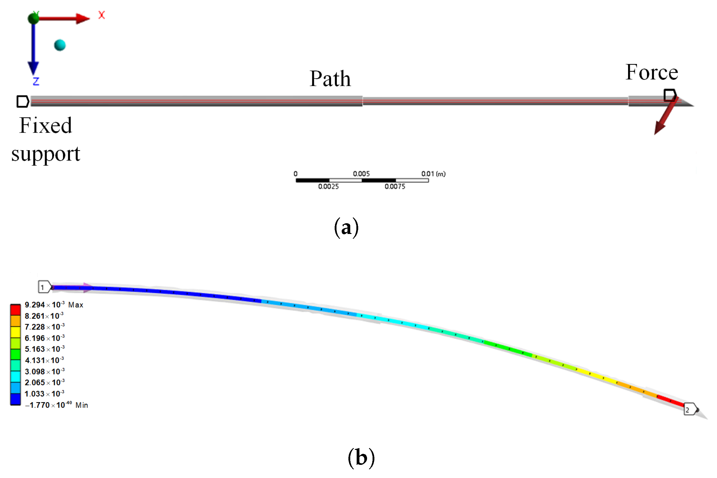
2.4. Simulation of the Effect of Stylet Extension Length on Deflection

Fixing the stylet diameter to 0.4 mm, the deflections of the stylet at different extension lengths are described in Figure 6. To verify that w L s 3 , a polynomial fit with a degree of 3 (the equation is a x 3 + b ) is selected and the fitted curves are y 1 = 0.001583 x 3 + 8.05 ,   R 2 = 0.9977 (Structure 1), y 2 = 0.0004836 x 3 + 7.828 ,   R 2 = 0.9881 (Structure 2), and y 3 = 0.0004906 x 3 + 7.831 ,   R 2 = 0.9957 (Structure 3).
Obviously, Structure 1, shown in Figure 6a, has a larger deflection and is most affected by the extension length. The tip deflections of the three structures in Figure 6d are proportional to the cube of the stylet extension length, indicating that curvature can be controlled by adjusting the length of the stylet extending out of the tube.
The theoretical deflection of Structure 1 can be derived from Equation (15) and is plotted in Figure 6d. It should be noted that in Equation (15), the other parameters, such as Young’s modulus, total length, etc., are consistent with the simulation settings in Table 2 except for the external force F, which is the transverse component of the simulated load of 0.3 N, i.e., F = 0.3 cos ( π / 6 ) . The fitted curve for the theoretical deflection is y t = 0.001631 x 3 + 7.925 ,   R 2 = 0.985 . The theoretical and simulated deflections of Structure 1 exhibit good agreement when the axial force Q is neglected. At an extension length of 15 mm, the relative error is 4.9%. The error may be due to the effect of the mesh quality and the neglect of the lateral force Q.
Figure 5d and Figure 6d show that both the stylet diameter and length influence the deflection. However, the small range of variation in stylet diameter results in limited control over the deflection. Once the needle is manufactured, its diameter is fixed and difficult to change. In contrast, the effect of the stylet extension length on the tip deflection is more significant, and the length of the stylet protruding from the tube is adjustable. Consequently, the solution of adjusting the stylet extension length is adopted and used to design the flexible needle with variable stiffness. Structure 1, whose deflection is most strongly affected by the stylet extension length, offers greater maneuverability and is thus selected.

3. Results

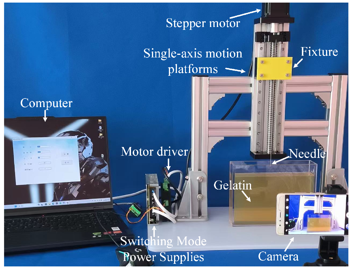
3.1. Experimental Setup

The variable-stiffness needle requires a nitinol stylet used together with a nitinol tube. Considering the price of nitinol tubing, a stainless steel tube was chosen instead, as shown in Figure 7. Using a straightedge and calipers, the following measurements were taken: tube diameter of 0.8 mm, stylet diameter of 0.4 mm, tip length of 5 mm, and tip angle of 28°.
A puncture system is built as illustrated in Figure 8, similar to our previous report [24], consisting mainly of a computer (Lenovo Group Limited, Beijing, China), a single-axis motion platform (Shandong Bote Precision Industry Co., Jining, China), a camera (Huawei Technologies Co., Ltd., Shenzhen, China), a flexible needle (Jiangyin Fasten-PLT Materials Science Company Ltd., Wuxi, China), and gelatin (10 wt%, 15 wt%, 20 wt%). The computer is connected to the driver via USB and controls the single-axis motion platform to adjust the insertion point and perform the puncture operation. Gelatin has a Young’s modulus of approximately 40 KPa, which is close to the Young’s modulus of 20 KPa of isolated porcine liver, and is a commonly used bionic soft tissue material [22,27]. Experiments are conducted to verify that the flexible needles with different structures exhibit different bending deflections. During the puncture process, there is no need to rotate the needle; thus, the flexible needle only moves in the plane. The camera is mounted on a tripod, as perpendicular as possible to the deflection plane of the flexible needle. The puncture trajectory is recorded, which is then used to measure and calculate the needle deflection.

3.2. Effect of Needle Stiffness on Puncture Trajectory

Before the experiments, the actual distance between the pixel points in the picture needed to be determined. We took a photo with a straightedge placed vertically next to the flexible needle and processed the image in MATLAB R2021b. This allowed us to calculate the actual distance corresponding to adjacent pixel points, which was found to be 0.0172 mm. Note that the origin of the pixel coordinate system is in the upper-left corner of the original photo, which is not conveniently marked here.
Punctures were performed at extension lengths of 0 mm, 2 mm, 4 mm, 6 mm, and 8 mm, respectively, at a puncture speed of 4 mm/s and an advance length of 100 mm. Extraction results of needle punctures in 20 wt% gelatin at an extension length of 2 mm are exhibited in Figure 9a–c, and the deflection extraction steps are as follows:
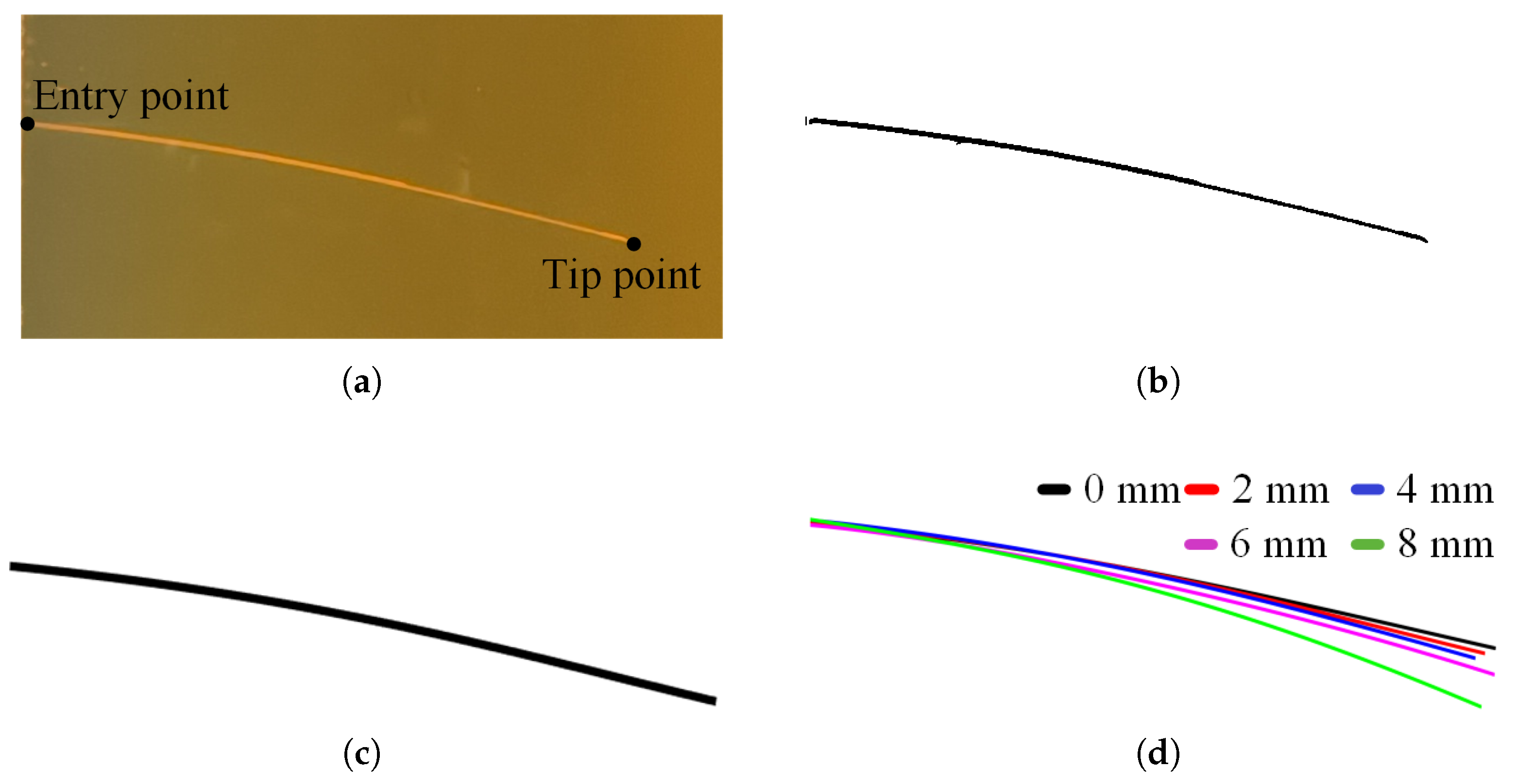
  • The insertion point was captured in MATLAB R2021b and the region within 300 px × 650 px was intercepted, as demonstrated in Figure 9a.
  • Binarization was performed with a threshold of 0.6 to extract the flexible needle, as in Figure 9b.
  • Discrete points were fitted to minimize data loss during extraction and to remove shadow interference caused by gelatin damage. The curves after second-order Fourier fitting are plotted in Figure 9c.
The pixel values of the needle entry point and tip point (as marked in Figure 9a) were extracted in MATLAB R2021b to obtain the deflection of the three flexible needles. The deflection can be calculated by ( y e n t r y y t i p ) d p , where y e n t r y and y t i p are the y-coordinate of entry pixel point and tip pixel point, and d p = 0.0172 mm is the actual distance corresponding to the adjacent pixel points. Five sets of punctures were made at each extension length. The deflections in 20 wt%, 15 wt%, and 10 wt% gelatin are listed in Table 3, Table 4 and Table 5 and plotted in Figure 10.
In Equation (15), the deflections are in a cubic relationship with the stylet extension length. The degree of the curve-fitted polynomial is set to 3, which is the same as in the theoretical model. The fitted equations for the deflections in 10%, 15%, and 20% gelatin are y = 0.008732 x 3 + 8.152 ,   R 2 = 0.9981 ;   y = 0.01315 x 3 + 14.87 ,   R 2 = 0.997 ;   y = 0.01648 x 3 + 18.17 ,   R 2 = 0.9908 . It can be seen that as the mass fraction increases, both the cubic term coefficient and the initial deflection in the fitted equations increase. This can be attributed to the increase in transverse force acting on the needle tip, resulting in greater needle deflection. The fitted curves exhibit a high degree of accuracy in matching the data points and effectively describe the relationship between deflection and stylet length, which aligns with the theoretical analysis. Compared to the linear relationship obtained by Bui et al. [17], our cubic relationship has a better fit, offering a more accurate representation of the relationship between the deflection and the control offset.
From Table 3, deflection consistency is better when the stylet is extended for a shorter length than when it is extended for a longer length. The reasons for the errors may be as follows:
  • The increase in temperature of the gelatin affected its mechanical properties, even though the air conditioner had been set to 25 °C.
  • Entry points and tip points are collected manually, which inevitably leads to errors.
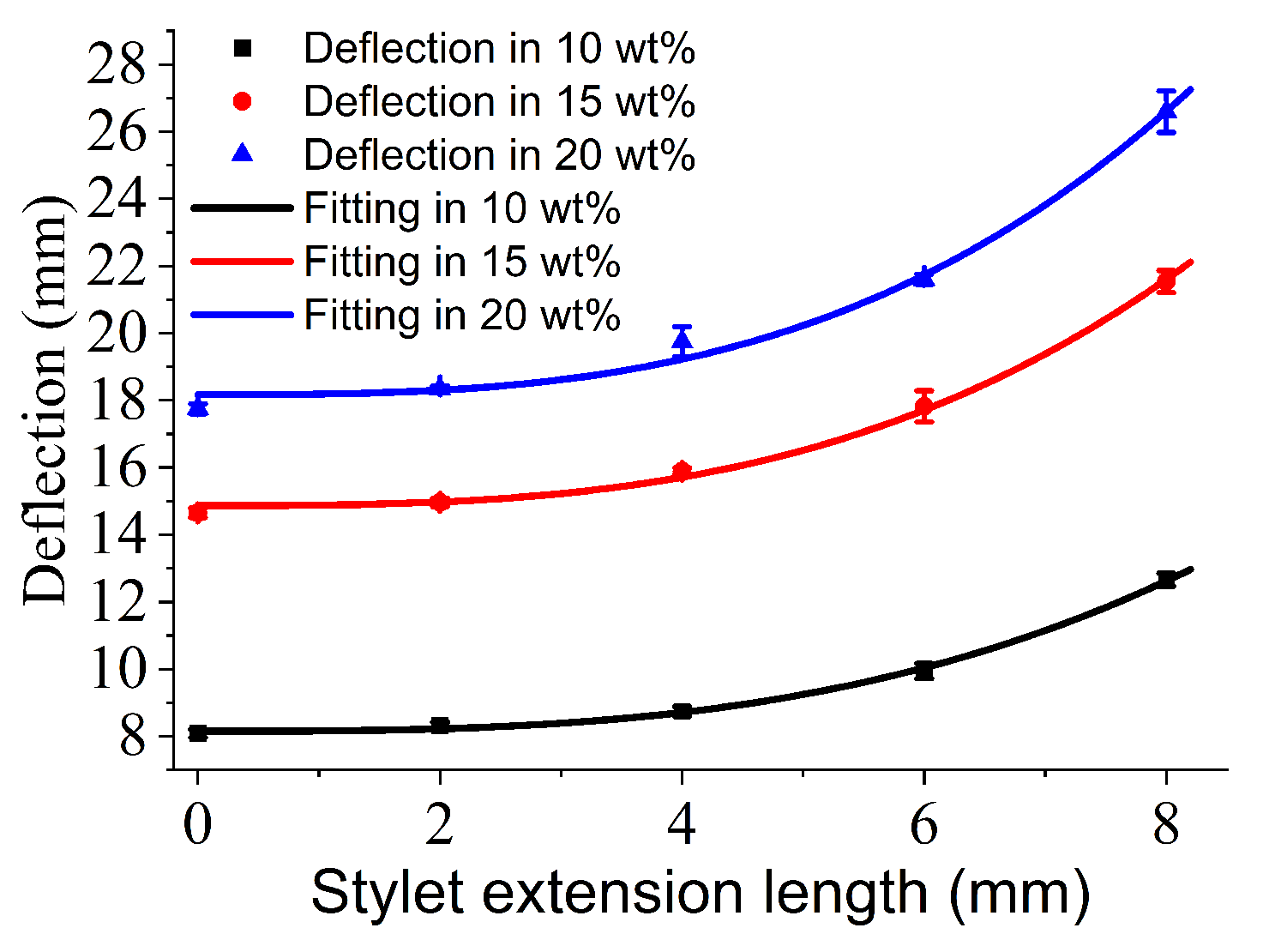
  • Feed errors were caused by motor vibration, motor temperature rise, low speed friction, etc. This effect is more pronounced with thin rods. This can be a key factor that leads to larger standard deviation at an extension length of 8 mm. However, these errors are acceptable.
It should be noted that we were unable to compare the experimental deflection with the theoretical deflection for the following reasons: (1) We used the Timoshenko beam theory for static structural analysis, whereas the piercing process is dynamic and the bending deflection is influenced by the insertion depth, which is not included in our model and may require further kinetic analysis. (2) We considered the tip length L shown in Figure 1 for the effect on needle deflection, but the tip length is related to structural parameters such as the diameters of the tube and the stylet. The effective needle length is difficult to determine and requires more in-depth mechanical analysis. (3) Figure 10 demonstrates that cutting resistance influences bending deflection based on piercing results of gelatin with varying mass fractions. However, we are currently unable to directly measure the cutting force at the needle tip, which renders the deflection model incapable of providing predictions. Nevertheless, the experimental results preliminarily confirm that controlling the length of the stylet extending out of the tube can alter the stiffness of the needle, allowing for manipulation of the puncture trajectory.

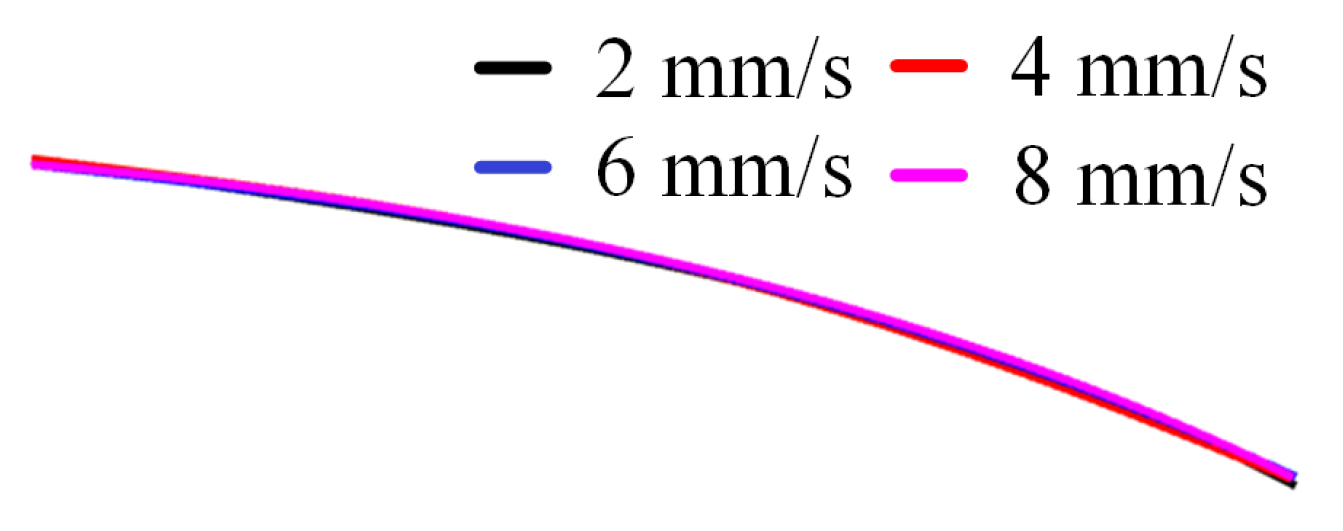
3.3. Effect of Puncture Speed on Puncture Trajectory

The speed of the flexible needle puncture is generally less than 10 mm/s [20]. The needles with stylet lengths of 0 mm, 2 mm, 4 mm, 6 mm, and 8 mm were inserted at speeds of 2 mm/s, 4 mm/s, 6 mm/s, and 8 mm/s, respectively, with an advance length of 100 mm. The deflections of the flexible needle with a stylet length of 6 mm are plotted in Figure 11 and listed in Table 6.
The causes of the errors are the same as those analyzed in Section 3.2. It can be seen that the structural stability of the needle with longer extension length is poor and it is more susceptible to the effects of motor vibration and friction. The results demonstrate that in flexible needles with identical extension lengths, constant-speed puncture within 2–8 mm/s exhibits no significant variation in bending deflection.

4. Conclusions

In this paper, a deflection model of a variable-stiffness flexible needle is established, and the influence of parameters such as the stylet diameter and extension length on bending is analyzed and optimized by simulation. The puncture experiments show that the deflection of the flexible needle is independent of the puncture speed. When inserted to a depth of 100 mm, the variable-stiffness needle with a diameter of 0.4 mm and an extension length of 8 mm exhibits 8.841 mm more deflection than the conventional flexible needle (diameter: 0.8 mm, which is equivalent to the variable-stiffness needle at 0 mm extension length). There is a cubic relationship between the bending deflection w and the length of the stylet extending out of the tube L s : w L s 3 .
The advantages of the proposed technology can be summarized as follows: (1) The developed deflection model effectively identifies key factors influencing the bending behavior of the variable-stiffness flexible needle; (2) the simplified structural design eliminates the need for complex actuation mechanisms (e.g., tendon wires or shape memory alloys), reducing manufacturing costs and operational complexity; (3) dynamic curvature control achieved by adjusting the stylet extension length enhances the flexibility of the puncture path.
This study qualitatively analyzes the relationship between needle deflection and stylet extension length. In the future, we will implant three-dimensional force sensors to analyze the lateral force F and axial force Q at the beveled tip and study their contribution to deflection. A kinetic model that accounts for tissue interaction forces, such as friction and anisotropy, will be developed to predict deformation during puncture in real time.

Author Contributions

Conception, design, acquisition of the data, and drafting of the article: G.W., Z.L. and K.L.; acquisition and interpretation of the data: H.Y. and Z.Z.; writing and editing: G.W. All authors have read and agreed to the published version of the manuscript.

Funding

This work was supported by Natural Science Foundation of Shandong Province under Grant No. ZR2024QF082; Doctoral Research Fund Project of Shandong Jianzhu University under Grant No. X24034; Youth Advisor Visiting Program of Shandong Provincial Department of Education; and Shandong Provincial Key R&D Program under Grant No. 2019GGX104056.

Institutional Review Board Statement

Not applicable.

Informed Consent Statement

Not applicable.

Data Availability Statement

The original contributions presented in this study are included in the article. Further inquiries can be directed to the corresponding author.

Conflicts of Interest

The authors declare that they have no conflicts of interest.

References

  1. Segato, A.; Di Marzo, M.; Zucchelli, S.; Galvan, S.; Secoli, R.; De Momi, E. Inverse reinforcement learning intra-operative path planning for steerable needle. IEEE Trans. Biomed. Eng. 2022, 69, 1995–2005. [Google Scholar] [CrossRef] [PubMed]
  2. Zhang, S.L.; Chen, J.C.; Sun, H.K.; Qi, Z.; Zhang, H. A scientometric review of medical flexible needle systems in surgery: Signal processing, navigation and control. Math. Biosci. Eng. 2024, 21, 627–642. [Google Scholar]
  3. Duan, Y.Z.; Ling, J.; Feng, Z.; Ye, T.T.; Sun, T.R.; Zhu, Y.C. A survey of needle steering approaches in minimally invasive surgery. Ann. Biomed. Eng. 2024, 52, 1492–1517. [Google Scholar] [PubMed]
  4. Lin, D.J.; Wang, J.Y.; Jiao, N.I.; Wang, Z.D.; Liu, L.Q. A flexible magnetically controlled continuum robot steering in the enlarged effective workspace with constraints for retrograde yntrarenal surgery. Adv. Intell. Syst. 2021, 3, 2000211. [Google Scholar]
  5. Adebar, T.K.; Fletcher, A.E.; Okamura, A.M. 3-D ultrasound-guided robotic needle steering in biological tissue. IEEE Trans. Biomed. Eng. 2014, 61, 2899–2910. [Google Scholar] [CrossRef]
  6. de Jong, T.L.; van de Berg, N.J.; Tas, L.; Moelker, A.; Moelker, A.; van den Dobbelsteen, J.J. Needle placement errors: Do we need steerable needles in interventional radiology. Med. Devices-Evid. Res. 2018, 11, 259–265. [Google Scholar]
  7. Li, A.D.R.; Liu, Y.; Plott, J.; Chen, L.; Montgomery, J.S.; Shih, A. Multi-bevel needle design enabling accurate insertion in biopsy for cancer diagnosis. IEEE Trans. Biomed. Eng. 2021, 68, 1477–1486. [Google Scholar]
  8. Gidde, S.T.R.; Ciuciu, A.; Devaravar, N.; Doracio, R.; Kianzad, K.; Hutapea, P. Effect of vibration on insertion force and deflection of bioinspired needle in tissues. Bioinspir. Biomim. 2020, 15, 054001. [Google Scholar]
  9. Favaro, A.; Secoli, R.; Baena, F.R.Y.; De Momi, E. Model-based robust pose estimation for a multi-segment, programmable bevel-tip steerable needle. IEEE Robot. Autom. Let. 2020, 5, 6780–6787. [Google Scholar] [CrossRef]
  10. Aktas, A.; Demircali, A.A.; Secoli, R.; Temelkuran, B.; Baena, F. Towards a procedure-optimised steerable catheter for deep-seated neurosurgery. Biomedicines 2023, 11, 2008. [Google Scholar] [CrossRef]
  11. Deaton, N.J.; Brumfiel, T.A.; Yamamoto, K.K.; Elliott, D.; Patel, P. Towards steering a high-dose rate brachytherapy needle with a robotic steerable stylet. IEEE T. Med. Robot. Bio. 2023, 5, 54–65. [Google Scholar]
  12. Deaton, N.J.; Brumfiel, T.A.; Sarma, A.; Desai, J.P. Simultaneous shape and tip force sensing for the COAST guidewire robot. IEEE Robot. Autom. Let. 2023, 8, 3725–3731. [Google Scholar]
  13. Zhang, J.Y.; Fang, Q.; Xiang, P.Y.; Liu, L.L.; Xiong, R.; Wang, Y.; Lu, H.J. Flexible biopsy robot with force sensing for deep lung examination. Adv. Intell. Syst. 2024, 6, 2300107. [Google Scholar]
  14. Lu, M.Y.; Zhang, Y.D.; Lim, C.M.; Ren, H.L. Flexible needle steering with tethered and untethered actuation: Current states, targeting errors, challenges and opportunities. Ann. Biomed. Eng. 2023, 51, 905–924. [Google Scholar] [CrossRef] [PubMed]
  15. Padasdao, B.; Konh, B. Shape memory alloy actuators in an active needle modeling, precise assembly and performance evaluation. J. Manuf. Sci. Eng. 2021, 143, 021003. [Google Scholar]
  16. Yan, K.; Yan, W.Q.; Zeng, W.H.; Ding, Q.P.; Chen, J.H.; Yan, J.Y.; Lam, C.P.; Wan, S.; Cheng, S.S. Towards a wristed percutaneous robot with variable stiffness for pericardiocentesis. IEEE Robot. Autom. Let. 2021, 6, 2993–3000. [Google Scholar]
  17. Bui, V.K.; Park, S.; Park, J.O.; Ko, S.Y. A novel curvature-controllable steerable needle for percutaneous intervention. Proc. Inst. Mech. Eng. Part H J. Eng. Med. 2016, 230, 727–738. [Google Scholar]
  18. Xu, B.X.; Ko, S.Y. Planar trajectory following control with a curvature-controllable steerable needle: Preliminary modeling and simulation. In Proceedings of the 18th International Conference on Control, Automation and Systems, PyeongChang, Republic of Korea, 17–20 October 2018. [Google Scholar]
  19. Xu, B.X.; Ko, S.Y. 3D feedback control using fuzzy logic for a curvature-controllable steerable bevel-tip needle. Mechatronics 2020, 68, 102368. [Google Scholar] [CrossRef]
  20. Jiang, S.; Li, P.; Yu, Y.; Liu, J.; Yang, Z.Y. Experimental study of needle–tissue interaction forces: Effect of needle geometries, insertion methods and tissue characteristics. J. Biomech. 2014, 47, 3344–3353. [Google Scholar]
  21. Jushiddi, M.G.; Cahalane, R.M.; Byrne, M.; Mani, A.; Silien, C.; Tofail, S.A.M.; Mulvihill, J.J.E.; Tiernan, P. Bevel angle study of flexible hollow needle insertion into biological mimetic soft-gel: Simulation and experimental validation. J. Mech. Behav. Biomed. Mater. 2020, 111, 103896. [Google Scholar]
  22. Rox, M.; Emerson, M.; Ertop, T.E.; Fried, I.; Fu, M.Y.; Hoelscher, J.; Kuntz, A.; Granna, J.; Mitchell, J.E.; Lester, M. Decoupling steerability from diameter: Helical dovetail laser patterning for steerable needles. IEEE Access 2022, 8, 181411–181419. [Google Scholar] [CrossRef] [PubMed]
  23. Misra, S.; Reed, K.B.; Schafer, B.W.; Ramesh, K.T.; Okamura, A.M. Mechanics of flexible needles robotically steered through soft tissue. Int. J. Robot. Res. 2010, 29, 1640–1660. [Google Scholar] [CrossRef] [PubMed]
  24. Wei, G.Z.; Jiang, Q. A temperature-compensated force sensor based on a cascaded FPI for needle force sensing. Measurement 2022, 202, 111748. [Google Scholar] [CrossRef]
  25. Jushiddi, M.G.; Mulvihill, J.J.E.; Chovan, D.; Mani, A.; Shanahan, C.; Silien, C.; Tofail, S.A.M.; Tiernan, P. Simulation of biopsy bevel-tipped needle insertion into soft-gel. Comput. Biol. Med. 2019, 111, 103337. [Google Scholar] [CrossRef]
  26. Abayazid, M.; Roesthuis, R.J.; Reilink, R.; Misra, S. Integrating deflection models and image feedback for real-time flexible needle steering. IEEE Trans. Robot. 2013, 29, 542–553. [Google Scholar] [CrossRef]
  27. Song, L.; Su, T.; Gao, L.Y.; Zhang, Q.H. Indentation tests based on gelatin phantom. In Proceedings of the 3rd International Conference on Mechanical Engineering, Materials and Energy, Changsha, China, 9–10 November 2013. [Google Scholar]
Figure 1. Structure of stiffness-tunable flexible needle.
Applsci 15 03746 g001
Figure 2. Tip force distribution and simplified model. (a) Forces acting on the needle tip. (b) Equivalent model of a flexible needle with variable stiffness.
Applsci 15 03746 g002
Figure 3. Structures and cross sections of three variable-stiffness needles. (a) Structure 1. (b) Structure 2. (c) Structure 3. (d) Cross section of Structure 1. (e) Cross section of Structure 2. (f) Cross section of Structure 3.
Applsci 15 03746 g003
Figure 4. Simulation models in ANSYS WORKBENCH 2022R2. (a) Constraints and loads. (b) Simulation results for deflection (directional deformation along the Z-axis). The legend is in meters.
Applsci 15 03746 g004
Figure 5. Comparison of deflection for different stylet diameters under a stylet length of 20 mm. (a) Deflection of Structure 1. (b) Deflection of Structure 2. (c) Deflection of Structure 3. (d) Deflection fitting for three structures.
Applsci 15 03746 g005
Figure 6. Comparison of deflections for different stylet extension lengths. (a) Deflection of Structure 1. (b) Deflection of Structure 2. (c) Deflection of Structure 3. (d) Deflection fitting for three structures and theoretical values for Structure 1.
Applsci 15 03746 g006
Figure 7. Variable-stiffness flexible puncture needles.
Applsci 15 03746 g007
Figure 8. Experimental setup of puncture system.
Applsci 15 03746 g008
Figure 9. Needle punctures in 20 wt% gelatin. (a) Interception area of the needle with an extension length of 2 mm. (b) Binarized image of the needle. (c) Curve-fitted image of the needle. (d) Comparison of bending deflections of needles with different extension lengths.
Applsci 15 03746 g009
Figure 10. Deflection fitting of the stiffness-tunable flexible needles.
Applsci 15 03746 g010
Figure 11. Influence of puncture speed on flexible needle deflection.
Applsci 15 03746 g011
Table 1. Theoretical deflection under different stylet extension lengths.
Extension Length0 mm5 mm10 mm15 mm20 mm
Deflection
Bending deflection (mm)7.17888.040210.086214.070420.6389
Shear deflection (mm)0.00080.00130.00150.00170.0020
Total deflection (mm)7.17968.041510.087714.072120.6409
Bending deflection/Total deflection99.99%99.98%99.99%99.99%99.99%
Table 2. Simulation parameters of a flexible needle with variable stiffness.
Total Length (mm)Tip Angle (°)Tip Length (mm)
50305
Tube Diameter (mm)Stylet Diameter (mm)Stylet Length (mm)
0.80.8, 0.7, 0.6, 0.5, 0.40, 5, 10, 15, 20
Young’s Modulus (MPa)Poisson’s RatioLoad (N)
75,0000.30.3
Table 3. Deflections in 20 wt% gelatin.
Extension
Length
0 mm 2 mm 4 mm 6 mm 8 mm
Deflection
Deflection1 (mm)17.71618.23220.29621.67227.520
Deflection2 (mm)17.88818.23219.60821.67225.800
Deflection3 (mm)17.88818.40419.43621.67226.488
Deflection4 (mm)17.71618.40419.26421.67226.488
Deflection5 (mm)17.54418.40420.12421.32826.66
Average (mm)17.75018.33519.74621.60326.591
SD (mm)0.1440.0940.4450.1540.615
Table 4. Deflections in 15 wt% gelatin.
Extension
Length
0 mm 2 mm 4 mm 6 mm 8 mm
Deflection
Deflection1 (mm)14.44815.13615.82417.02820.984
Deflection1 (mm)14.79214.96415.82417.88821.844
Deflection1 (mm)14.79214.96415.99617.88821.500
Deflection1 (mm)14.62014.79215.82418.06021.672
Deflection1 (mm)14.62014.96415.99618.23221.672
Average (mm)14.65414.96415.89317.81921.534
SD (mm)0.1440.1220.0940.4650.331
Table 5. Deflections in 10 wt% gelatin.
Extension
Length
0 mm 2 mm 4 mm 6 mm 8 mm
Deflection
Deflection1 (mm)8.0848.4288.7729.80412.384
Deflection2 (mm)8.2568.2568.77210.14812.728
Deflection3 (mm)7.9128.2568.6009.63212.728
Deflection4 (mm)8.0848.2568.94410.14812.900
Deflection5 (mm)8.0848.4288.6009.97612.556
Average (mm)8.0848.3258.7389.94212.659
SD (mm)0.1220.0940.1440.2240.196
Table 6. Deflections of stiffness-tunable flexible needles.
Extension
Length
0 mm 2 mm 4 mm 6 mm 8 mm
Puncture
Speed
At 2 mm/s (mm)18.23218.57619.60821.15627.004
At 4 mm/s (mm)17.88818.40419.43621.67226.488
At 6 mm/s (mm)18.0618.57619.43621.84426.66
At 8 mm/s (mm)18.23218.74819.7821.67226.66
Average (mm)18.10318.57619.56521.58626.703
SD (mm)0.1650.1400.1650.2980.216
Disclaimer/Publisher’s Note: The statements, opinions and data contained in all publications are solely those of the individual author(s) and contributor(s) and not of MDPI and/or the editor(s). MDPI and/or the editor(s) disclaim responsibility for any injury to people or property resulting from any ideas, methods, instructions or products referred to in the content.

