Article

Long-Term Anti-Corrosion Performance of Ultra-High Content Inhibitor Loaded Gel-Epoxy Solid Inhibitor with Temperature-Responisve Effect

1
Sichuan Energy Investment Hydrogen Industry Investment Co., Ltd., Chengdu 610000, China
2
School of Chemistry and Chemical Engineering & Institute for Carbon Neutrality, Southwest Petroleum University, Chengdu 610500, China
*
Authors to whom correspondence should be addressed.
Appl. Sci. 2025, 15(7), 3964; https://doi.org/10.3390/app15073964
Submission received: 17 February 2025 / Revised: 16 March 2025 / Accepted: 18 March 2025 / Published: 3 April 2025

Abstract

:
This study investigates the development and performance of a novel GE-EP@OIM solid corrosion inhibitor for enhancing long-term corrosion protection in the oil-and-gas industry’s corrosive environment. The inhibitor was synthesized by incorporating organic imidazole molecules (OIMs) into a Gel-Epoxy (GE-EP) matrix, achieving an OIM-loading capacity of approximately 34.75% (generally reported capacity is up to 20%). The solid inhibitor was designed as a smart material, which exhibits temperature-responsive release behavior in a chlorine-corrosive environment. A combination of electrochemical measurements, weight loss testing, and scanning electron microscopy (SEM) was employed to assess the inhibitor’s performance. The results demonstrate that GE-EP@OIMs significantly improve corrosion resistance, particularly at elevated temperatures (50 °C), with the long-term protection effect serving as a key highlight, maintaining efficacy for up to 60 days, and it shows enhanced stability compared to conventional inhibitors. While the mechanical properties of GE-EP@OIMs are slightly diminished due to the incorporation of OIMs, the inhibitor still meets the necessary fluidity and performance criteria for medium- to long-term applications. This material shows considerable promise for mitigating corrosion in oilfield operations, especially for downhole tubing, and presents a cost-effective solution to the widespread corrosion challenges in the industry.

1. Introduction

Corrosion remains a critical challenge in the oil-and-gas industry, with severe safety, economic, and environmental implications. Global losses due to corrosion are estimated to exceed USD 2.5 trillion annually, representing 3–4% of the global GDP [1]. Oil and natural gas, which account for over 60% of global energy consumption, continue to be indispensable, despite the rise of alternative energy sources [2]. In this context, carbon steel, despite its susceptibility to corrosion, is widely used in oil-and-gas exploration due to its cost-effectiveness and mechanical properties. In China alone, over 3.5 million tons of carbon steel is used annually in the sector [3]. China’s unique geological conditions exacerbate corrosion risks, particularly for downhole tubing materials exposed to high-temperature and high-pressure environments and aggressive media such as CO2, H2S, and saline water. Enhanced oil recovery (EOR) techniques like acid fracturing and CO2 flooding further increase the corrosive challenges by raising the water content and corrosive ion concentrations [4]. The resulting severe corrosion causes mechanical failures, production halts, and billions of dollars in losses annually. Moreover, corrosion-related leaks contribute to greenhouse gas emissions, hindering carbon neutrality efforts [5].
To address these issues, a range of corrosion protection measures have been improved, including material enhancement, coatings, and corrosion inhibitors. Research on corrosion inhibitors has demonstrated their efficacy in mitigating corrosion in oil-and-gas exploration environments [6]. The utilization of corrosion inhibitors is especially noteworthy for its cost-effectiveness, ease of application, and versatility across diverse scenarios. Nevertheless, traditional corrosion inhibitors still encounter significant limitations, such as a short protection period and the lack of responsiveness to the change of corrosive media, which need further investigation. Corrosion inhibitors embedded in solid matrices can be designed to release through various mechanisms, including mechanical deformation or wear, chemical reactions, electromagnetic activation, and thermal response. Among these, temperature responsive release is particularly advantageous in oilfield applications, where temperature fluctuations significantly impact corrosion rates. The ability of GE-EP@OIMs to autonomously regulate its release based on temperature ensures effective protection by accelerating inhibitor release under high-temperature, highly corrosive conditions while maintaining long-term inhibition in moderate conditions.
Conventional liquid corrosion inhibitors, although widely employed, possess notable drawbacks, namely, uneven dispersion and a brief protection duration. In production environments, liquid inhibitors frequently fail to form a uniform protective film, resulting in inconsistent corrosion protection. This is especially pronounced in turbulent flow or complex geometric configurations where local inhibitor concentrations vary [7]. Their effectiveness is further curtailed in high-temperature and high-salinity environments, where they degrade rapidly and offer protection for merely a few hours to a few days. Frequent reapplication not only escalates operational costs but also diminishes efficiency [8]. Furthermore, the dependence on external equipment, such as high-pressure injection systems, exacerbates these challenges. These systems are essential for the delivery of liquid inhibitors but entail a high initial investment, continuous maintenance, and substantial energy consumption. This reliance augments operational complexity, particularly in remote or offshore oil fields, and induces inefficiencies, especially during equipment failures, which can precipitate production downtime [9]. Moreover, high-pressure systems struggle to ensure the uniform distribution of inhibitors across extensive pipeline networks, further undermining their effectiveness.
These limitations accentuate the exigency for advanced corrosion protection methodologies endowed with innovative delivery mechanisms, which are capable of obviating equipment dependency, guaranteeing uniform distribution, and furnishing prolonged protection, thereby augmenting both practicality and economic viability. Environmental and operational considerations present supplementary impediments for conventional inhibitors. A multitude of inhibitors pose environmental hazards, such as toxicity to aquatic ecosystems or potential bioaccumulation, thereby mandating stringent handling and disposal protocols that augment operational complexity [10]. Additionally, inhibitors customarily necessitate specific conditions, such as narrow temperature or pH ranges, to attain optimal functionality. For instance, inhibitors efficacious in acidic milieus may prove ineffective in neutral or alkaline conditions [11]. These limitations underscore the desideratum for environmentally benign and versatile alternatives that ensure long-term and reliable protection.
In response to the limitations of traditional inhibitors, solid or smart inhibitors have emerged as innovative alternatives. Solid inhibitors are meticulously engineered to encapsulate active corrosion-inhibiting agents within carrier materials, such as hydrogels, polymeric matrices, or microcapsules, to ensure controlled and sustained release. This strategy mitigates the premature exposure of inhibitors to external conditions, consequently enhancing their stability and protracting their protective tenure in aggressive environments [12]. Moreover, the encapsulation technique facilitates a gradual release, which has been demonstrated to uphold efficacious concentration levels over extended durations, rendering them particularly apt for applications in high-pressure and high-temperature scenarios [13]. Smart inhibitors, such as those made of hydrogel or gel-like matrices, incorporate advanced functionalities, namely pH sensitivity, temperature responsiveness, and self-healing capabilities. These systems are capable of releasing inhibitors in a controlled manner contingent upon environmental triggers, offering bespoke protection for downhole tubing under fluctuating conditions. Recent studies, such as those conducted by [14,15], have evinced the efficacy of pH-sensitive hydrogels in dynamically modulating inhibitor release rates in acidic environments. Furthermore, ref. [16] accentuated temperature-responsive materials that optimize inhibitor performance under fluctuating thermal conditions, while the authors of [17] explored self-healing hydrogels capable of significantly elongating protection durations.
Despite their potential, extant solid inhibitors encounter challenges, including low loading capacities (typically below 20%), circumscribed release duration (frequently less than 48 h), and nebulous release mechanisms. For example, the authors of [18] demonstrated that traditional solid inhibitors often fail to sustain release beyond 48 h in high-pressure CO2 environments, thereby circumscribing their application. Similarly, the authors of [19] highlighted the difficulties in optimizing release kinetics, which are of pivotal importance for long-term protection in varying corrosive conditions. These lacunae necessitate further research to develop inhibitors with enhanced loading capacities, protracted release times, and robust corrosion protection performance.
This paper focuses on the synthesis and assessment of a high-loaded solid corrosion inhibitor, namely GE-EP@OIMs, which is devised with the intention of surmounting the constraints inherent in conventional inhibitors. This research endeavor is directed towards the development of a novel solid inhibitor characterized by a substantially elevated loading capacity (exceeding 30%) and an extended release period (up to 30 days). It also undertakes an investigation into the release kinetics and mechanisms under diverse environmental circumstances and to appraise its long-term corrosion protection efficacy on L80 carbon steel within simulated downhole settings. The outcomes of this study are poised to offer pragmatic solutions to augment corrosion protection within the oil-and-gas industry, thereby facilitating safer and more sustainable energy generation. Moreover, this investigation may well blaze a trail in the broader utilization of high-loaded solid inhibitors in sectors such as marine engineering and chemical processing, where corrosion represents a formidable challenge. The GE-EP@OIMs solid corrosion inhibitor is classified as an intelligent material due to its temperature-responsive release mechanism, allowing it to autonomously regulate the release of OIMs based on environmental conditions. This smart behavior enhances its long-term corrosion protection efficiency, reducing unnecessary inhibitor consumption and ensuring effective performance in dynamic oilfield environments. Notably, marine engineering has conventionally placed reliance on coatings and cathodic protection rather than corrosion inhibitors, rendering the introduction of high-loaded solid inhibitors a potentially revolutionary strategy for contending with corrosion in this domain. Future research initiatives might explore the integration of smart materials with advanced sensing technologies for the purposes of real-time surveillance and adaptive corrosion protection.

2. Experiment Details

2.1. Sample Preparation and Corrosion Testing Procedures

Electrochemical experiments and weight loss tests were designed to study the corrosion inhibition performance and inhibition mechanism of solid corrosion inhibitors. L80 carbon steel was selected as the corrosion sample, and its chemical composition is shown in Table 1. The surface of L80 carbon steel (40 mm × 13 mm × 2 mm) was polished step by step using SiC sandpaper (280#, 500#, 1000#, and 2000#) until a mirror finish was achieved. The surface was cleaned sequentially with acetone, deionized water, and anhydrous ethanol and then dried with cold air. The sample was then connected to a wire. A 10 × 10 mm2 area was reserved on the surface, and the remaining area was sealed with red adhesive. The test solution was prepared by soaking the solid corrosion inhibitor in a 3.5 wt.% NaCl solution under different conditions for varying time periods.

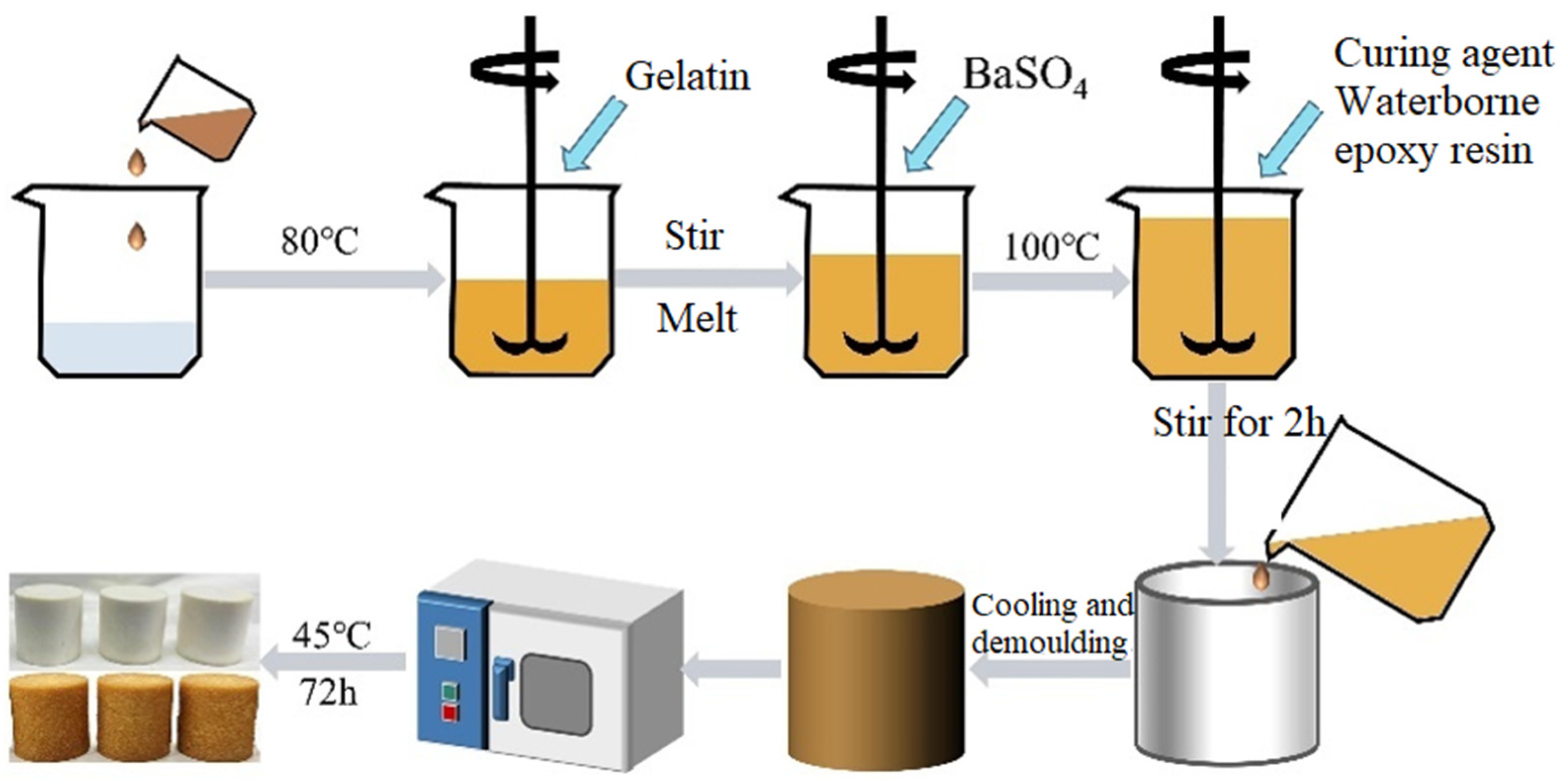
2.2. Synthesis of GE-EP@OIMs Smart Corrosion Inhibitor

The bonding preparation process of GE-EP@OIMs is illustrated in Figure 1. A 500 mL beaker was placed in a constant-temperature oil bath, and 30 mL of deionized water was poured in and heated to 80 °C. Oleic acid imidazoline (OIM) (50 g) was added and completely dissolved using an electric stirrer. The solution temperature was maintained at 80 °C, and 20 g of gelatin was added, stirred continuously until the gelatin was fully melted. BaSO4 (5 g) was then added to the solution as a weighting agent to control the density of the solid corrosion inhibitor. The temperature was increased to 100 °C while stirring for 2 h to evaporate the water in the mixture. Finally, 60 g of waterborne epoxy resin and 20 g of curing agent were added to the beaker in a 3:1 ratio. After thorough stirring, the mixture was quickly poured into a silicone mold (20 × 20 × 20 mm) and allowed to cool and solidify. Once the material had completely cooled and solidified, it was demolded and placed in a 45 °C vacuum drying oven for 72 h to obtain the GE-EP@OIMs solid corrosion inhibitor. The solid corrosion inhibitor GE-EP@OIMs has a yellow-brown color, an average mass of 15.7377 g, and dimensions of 20 mm in diameter and height.

2.3. Characterization Methods for Solid Corrosion Inhibitors

2.3.1. Scanning Electron Microscope

To observe the microscopic morphology of the GE-EP@OIMs solid corrosion inhibitor in its pre-release and post-release states, as well as the microscopic morphology of L80 carbon steel after corrosion, a scanning electron microscope (The ZEISS EVO MA15 scanning electron microscope is manufactured by Carl Zeiss Microscopy GmbH, Jena, Germany) was used. Before SEM testing, the samples were dried to remove moisture. The two non-conductive solid corrosion inhibitors were treated with gold spraying. The acceleration voltage was set to 20 kV, and the element distribution and content of each sample were analyzed using a matching energy dispersive spectrometer (EDSThe Oxford X-Max 20 Energy Dispersive Spectrometer (EDS) manufactured by Oxford Instruments plc, Abingdon, Oxfordshire, United Kingdom.

2.3.2. Infrared Spectrum Test

The solid corrosion inhibitor was crushed using a pulverizer, mixed with potassium bromide in a ratio of 1:100, and ground evenly. A tablet press was then used to punch a disc-shaped sample. In the Nicolet 6700 Infrared Analyzer is manufactured by Thermo Fisher Scientific Inc., Waltham, MA, USA, the infrared light wavelength range was selected as 400–4000 cm⁻1, the sample was scanned, and the infrared spectrum was recorded. The functional groups were analyzed based on information such as peak intensity.

2.3.3. Thermal Stability Test

Referring to (GBT27761-2011) “Test Method for Weight Loss and Residual Amount of Thermogravimetric Analyzer”, ref. [20], the sample was subjected to thermogravimetric analysis using a thermal analyzer. The loading amount and thermal stability of the gel-type and cementing-type carriers on the corrosion inhibitor were estimated by recording the mass loss, mass loss rate, and thermal decomposition process of the sample during the heating process. The initial mass of the sample was 5–10 mg, the heating rate was 10 °C/min, and the temperature range was 40–600 °C. The release kinetics of OIMs from GE-EP@OIMs demonstrate an adaptive, temperature-driven response, where higher temperatures accelerate the release rate, enabling rapid protection in aggressive conditions, while lower temperatures slow down the release for extended inhibition. This self-regulating characteristic justifies classifying GE-EP@OIMs as a smart corrosion inhibitor, as it responds dynamically to environmental changes, optimizing corrosion protection efficiency. Various mechanisms can trigger the release of corrosion inhibitors, including mechanical wear, chemical dissolution, electromagnetic stimulation, and thermal activation. In this study, temperature-dependent release was selected as the primary mechanism due to its practical relevance in oilfield environments, where temperature variations influence corrosion rates and inhibitor efficiency. The ability of GE-EP@OIMs to increase release at higher temperatures (50 °C and 80 °C) aligns with the increased corrosion risks under these conditions, making it a self-regulating and efficient protection system.

2.3.4. Mechanical Properties Test

Referring to (GBT1040) “Determination of Tensile Properties of Plastics”, ref. [21], the mechanical properties of the two prepared solid corrosion inhibitors were tested at room temperature using an electronic universal testing machine (model ETM502C manufactured by Wance Technologies Co., Ltd., Shenzhen, Guangdong, China). The sample was a sheet specimen, and the tensile rate was 5 mm/min.

2.3.5. Raman Test

A Raman spectrometer (model BWS465-785S manufactured by B&W Tek, LLC, Newark, DE, USA) was used to study the adsorption of the OIM corrosion inhibitor components released by the solid corrosion inhibitor on the carbon steel surface. The wavelength of the light source used was 785 nm.

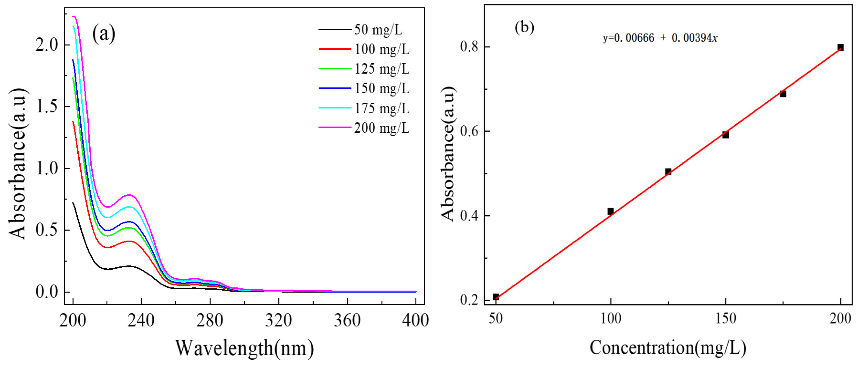
2.4. Release Behavior of OIM from GE-EP@OIMs

To establish the standard curve of oleic acid imidazoline, 0.1 g of oleic acid imidazoline was taken in a 100 mL volumetric flask, and deionized water was added to prepare a 1000 mg/L corrosion inhibitor solution. Subsequently, 5 mL, 10 mL, 12.5 mL, 15 mL, 17.5 mL, and 20 mL of this solution were taken and diluted with deionized water in 100 mL volumetric flasks to prepare 50 mg/L, 100 mg/L, 125 mg/L, 150 mg/L, and 175 mg/L OIM standard solutions. The absorption intensity of these corrosion inhibitor solutions of known concentrations was measured using a UV-visible spectrophotometer. The measurement results are shown in Figure 2. The maximum absorption wavelength of OIMs was found to be 233 nm, and the standard curve equation of OIMs was obtained in Formula (1):
y = 0.00666 + 0.00394 x

2.5. Corrosion Protection Performance of GE-EP@OIMs

2.5.1. Electrochemical Experiment

Electrochemical impedance spectroscopy (EIS) and potentiodynamic polarization scanning (PDP), Wuhan CorrTest Instruments Co., Ltd., Wuhan, Hubei Province, China. were used to investigate the corrosion inhibition performance and mechanism of solid corrosion inhibitors in 3.5 wt% NaCl solutions at 20 °C, 50 °C, and 80 °C and different release time. Three-electrode system was employed, with L80 steel as the working electrode, a Pt electrode as the auxiliary electrode, and a saturated calomel electrode as the reference electrode. An open circuit potential (OCP) test lasting 2 h was first conducted in a CS350, CorrTest Instruments Co., Ltd., Wuhan, Hubei Province, China electrochemical workstation to ensure the stability of the test system. Following this, an EIS test was performed with a 10 mV sinusoidal perturbation potential, with a measurement frequency range from 100,000 Hz to 0.01 Hz, and at a test temperature of 80 °C. The software ZSimp Win (version 1.0) was used to fit the impedance data, and the corrosion inhibition efficiency of the inhibitor was calculated using Formula (2):
n E I S ( % ) = ( R t o t a l R t o t a l 0 R t o t a l ) × 100
where R t o t a l 0   represents the total resistance of L80 in the corrosion solution, and R t o t a l   represents the total resistance of L80 in the corrosion solution with solid corrosion inhibitor ( R t o t a l = Rs + Rfilm+ Rct).
After the EIS test, a dynamic potential scan was immediately carried out with a scan range of −400–400 mV and a scan rate of 0.5 mVs−1. The measured polarization curve was fitted by the Tafel extrapolation method to obtain dynamic potential parameters such as self-corrosion current density (icorr), and the corrosion inhibition efficiency was calculated by Formula (3):
n T a f e l ( % ) = ( i c o r 0 i c o r i c o r 0 ) × 100
where i c o r 0   represents the current density of L80 in the corrosion solution; 0.1 μA·mm−2; i c o r   represents the current density of L80 in the corrosion solution with added solid corrosion inhibitor, 0.1 μA·mm−2.

2.5.2. Weight Loss Experiment

The weight of the sample (m1) was measured using a Sartorius Quintix 124-1S electronic analytical balance, with an accuracy of 0.1 mg. The sample was soaked in NaCl solution with and without the solid corrosion inhibitor, and the NaCl solution was replaced every 24 h. The L80 samples were taken out regularly. According to GB/T 16545-2015 [22], “Corrosion of Metals and Alloys—Removal of Corrosion Products from Corrosion Samples”, the prepared pickling solution was used to quickly remove the corrosion products from the sample surface. The surface was then cleaned with deionized water and ethanol, and the mass of the sample (m2) was recorded after drying with cold air. The corrosion rate (CR, mm/a) and corrosion inhibition efficiency (IE, %) were calculated using Formulas (4) and (5), respectively:
C R = Δ w × 87600 S t p
n w ( % ) = ( 1 C R C R 0 ) × 100
where Δw is the mass difference of the sample before and after the corrosion test, g; S is the surface area of the sample, cm2; t is the corrosion time, h; ρ is the density of the sample, g·cm−1; CR0 is the corrosion rate of the sample without adding the corrosion inhibitor, mm/a; CR is the corrosion rate of the sample after adding corrosion inhibitor, mm/a, as shown if Table 2 below

3. Results and Discussion

3.1. Characteristic of GE-EP@OIMs

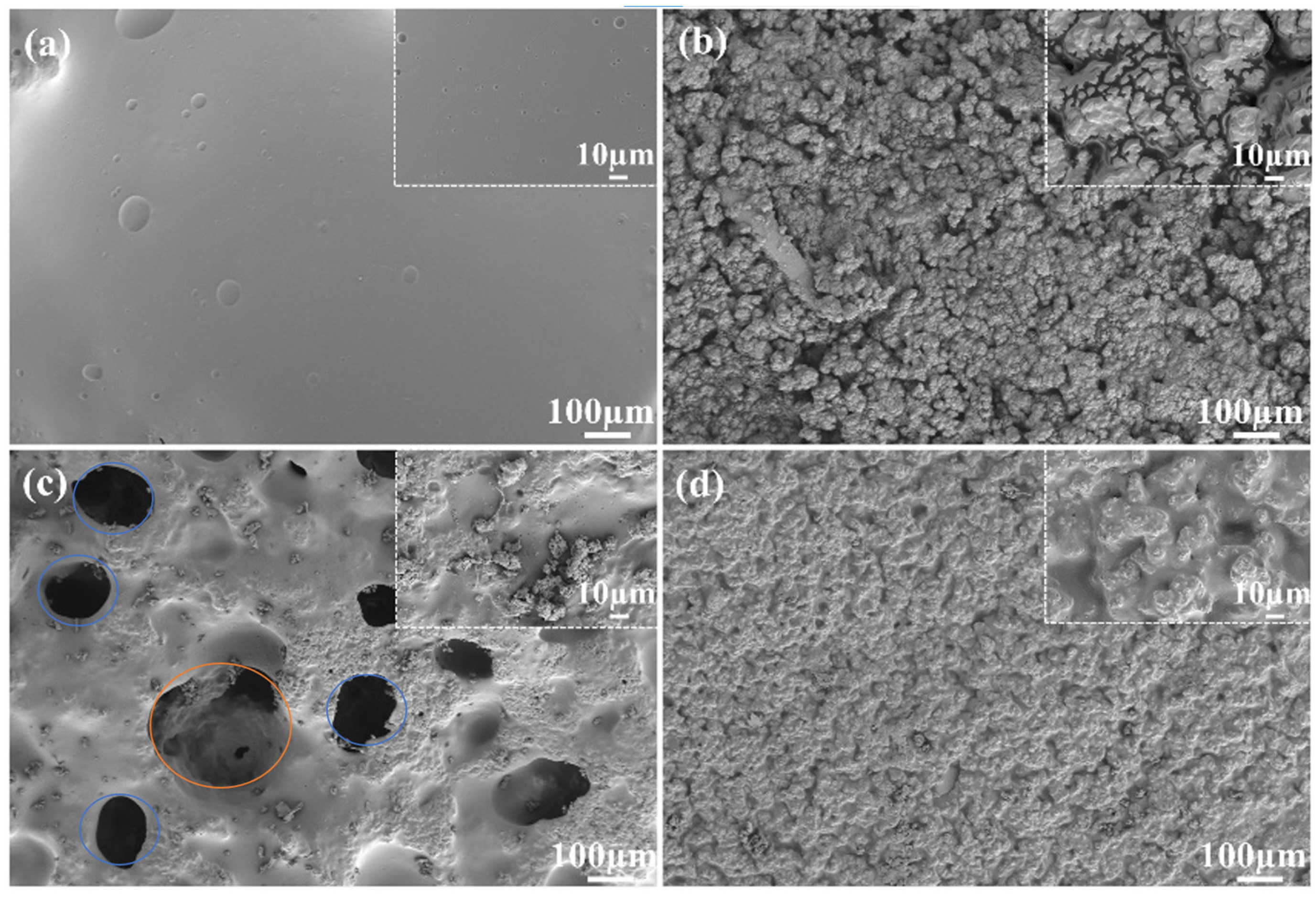
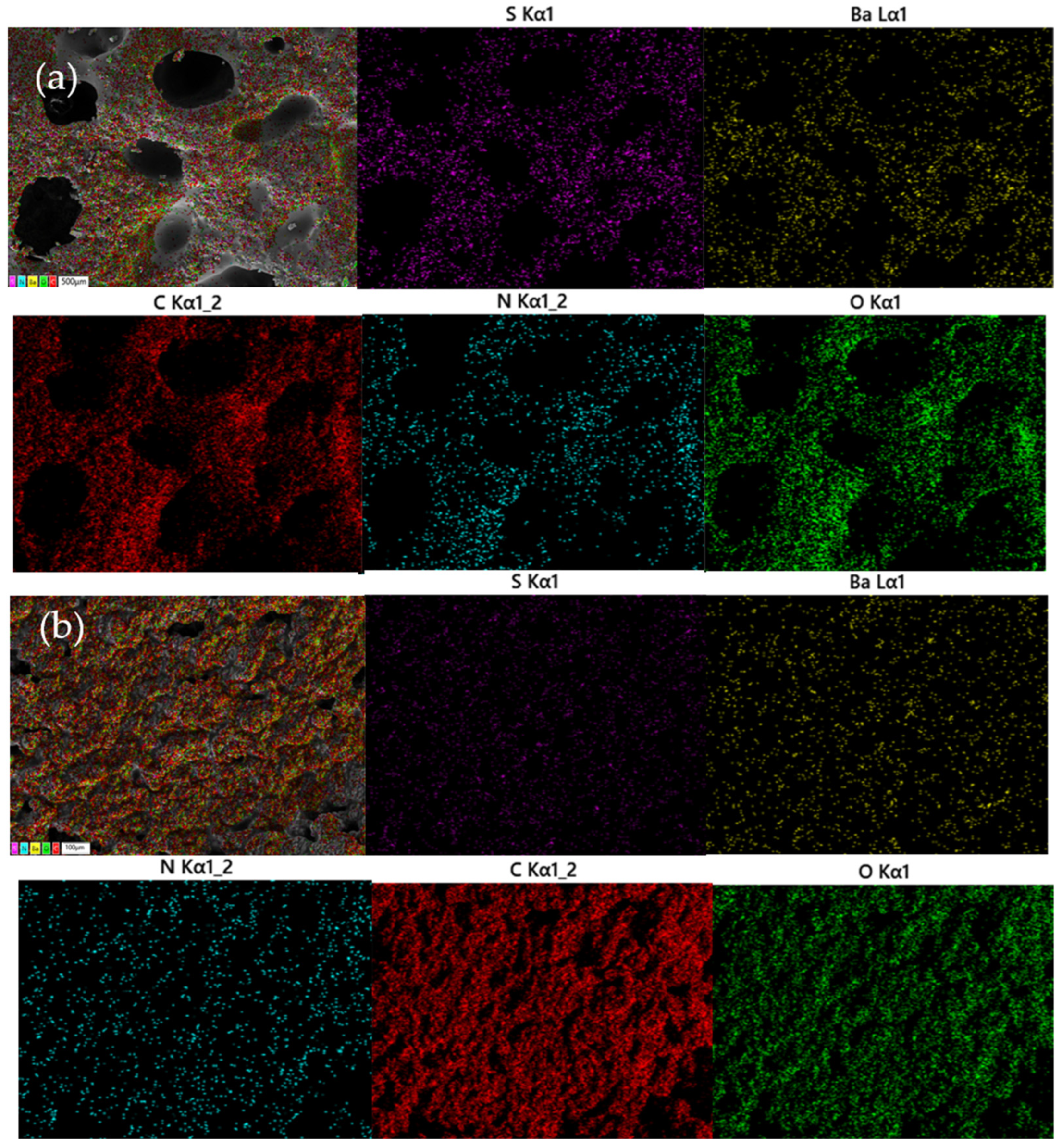
3.1.1. Surface Morphology of GE-EP@OIMs

Figure 3 shows the surface and internal morphology of the prepared GE-EP loaded with and without OIMs after vacuum drying. In the case of GE-EP without OIM loading, the internal morphology is characterized by non-uniformity and coarseness, with a multitude of spherical particles being present, these particles serve to create spatial accommodations for the subsequent incorporation of OIMs, as reported by [23]. However, the surface morphology of the GE-EP sample exhibits a smooth and planar appearance, which is an outcome of the specific preparation procedures employed. In contrast, for the GE-EP loaded with OIMs, the internal morphology, while still retaining a certain degree of roughness and topographical irregularities, demonstrates a significant reduction in such features compared to the OIM-free GE-EP. This phenomenon indicates the successful loading of OIMs, and furthermore, the addition of OIMs augments the binding forces between the epoxy resin, curing agent, gelatin, and BaSO4, culminating in a more homogeneous dispersion of each constituent. Additionally, it is observable that pores with diameters ranging from 100 to 200 μm are manifested on the surface of GE-EP@OIMs. These pores enhance the contact area between GE-EP@OIMs and the surrounding solution, thereby facilitating the release of the corrosion inhibitor.
Figure 4 presents the EDS analysis of the internal structure of GE-EP@OIMs, illustrating the distribution of key elements, including sulfur (S), barium (Ba), carbon (C), nitrogen (N), and oxygen (O), within the solid corrosion inhibitor matrix. The EDS maps reveal that these elements are uniformly distributed across both the surface and the interior of GE-EP@OIMs, with particular emphasis on their even dispersion around small pores on the surface. Such uniform distribution is indicative of the efficacious dispersibility of the matrix corrosion inhibitor, weighting agents, synergistic agents, and other constituents like cement. Notably, a disparity in elemental composition exists between the surface and the interior. Precisely, the abundances of Ba and S elements are relatively lower on the surface in contrast to the interior. This discrepancy can be ascribed to the gravitational sedimentation of BaSO4 particles during the cementation and molding procedures, which consequently engenders a marginally elevated concentration of these elements within the internal structure. The observed elemental distribution and its attendant uniformity substantiate the successful amalgamation of OIMs and other components, thereby contributing to the augmented performance of the material as a solid corrosion inhibitor.

3.1.2. FT-IR Analysis

Figure 5 presents the FT-IR results of OIM, GE-EP, and GE-EP@OIMs. It can be observed that the broad infrared absorption peak at 3440 cm⁻1 is associated with the antisymmetric stretching vibration of the −NH2 group present in OIMs, GE-EP, and GE-EP@OIMs [24]. The weak infrared absorption peaks at 2923 cm⁻1 and 2861 cm⁻1 correspond, respectively, to the asymmetric and symmetric stretching vibrations of -CH2, signifying the presence of longer alkyl chains in OIM, GE-EP, and GE-EP@OIMs (in accordance with the findings of [25]. All three substances manifest an infrared absorption peak at 1642 cm−1. In the case of OIMs, this peak is principally ascribed to the C=N bond within the five-membered ring and the C=C double bond vibration in the hydrophobic tail as per [25]. For GE-EP, the peak is predominantly due to the C=O bond and the C=C bond in the gelatin, as well as the C=C bond in the aromatic ring of the binder, bisphenol A water-based epoxy resin. The absorption peaks of GE-EP and GE-EP@OIMs at 1108 cm−1 are associated with the stretching vibration of the C−O−C functional group within the carrier. Additionally, OIMs exhibit the CO2 antisymmetric stretching vibration peak at 2350 cm−1. The peak at 1550 cm−1 corresponds to the C−N stretching vibration in the amine ethyl group of the side chain of OIMs. The peak at 1457 cm−1 is attributable to the C−N bond stretching vibration in the imidazole ring of OIMs, which represents a characteristic peak of OIMs. This peak is exclusive to OIMs and GE-EP@OIMs, thereby indicating the successful loading of OIMs onto GE-EP within the solid corrosion inhibitor. The peak intensity in GE-EP@OIMs is markedly lower than that in OIMs, which might be attributed to the encapsulation of OIMs by GE-EP (as proposed by [26]).

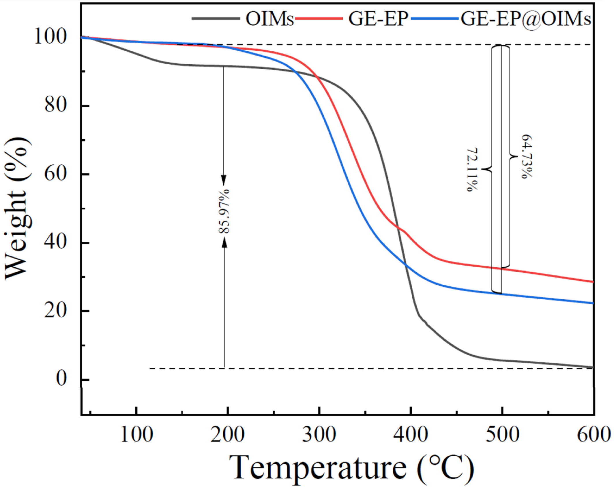
3.1.3. Thermostability and Inhibitor Loading Content of GE-EP@OIMs

Figure 6 presents the thermogravimetric and heat loss curves of the OIM corrosion inhibitor, the carrier GE-EP, and the solid corrosion inhibitor GE-EP@OIMs. The thermal degradation of GE-EP and GE-EP@OIMs occurs in two distinct stages: the first stage (40–200 °C) is primarily characterized by the volatilization of free and bound water within the samples, while the second stage (200–500 °C) corresponds to the decomposition of the chemical components in the samples. These curves illustrate the thermal behavior and stability of the materials under increasing temperatures.
The mass loss fractions of GE-EP and GE-EP@OIMs in stage 1 (40–200 °C) were similar, both significantly lower than those of OIMs, at 2.91% and 2.90%, respectively. In the second stage, both GE-EP and GE-EP@OIMs began to decompose at 200 °C, with the maximum degradation rates occurring at 332 °C and 327 °C, respectively. At 500 °C, degradation ceased in all samples, leaving 32.36% and 24.99% of undegraded substances, respectively. This demonstrates that the thermal stability of GE-EP@OIMs is further improved compared to that of PAM hydrogel, allowing it to be used in a corrosive environment at temperatures below 200 °C. The degradation process of GE-EP and GE-EP@OIMs in the second stage mainly involves (1) the breaking of the terminal aliphatic chain of the water-based epoxy resin (>300 °C) and partial cracking of the aromatic structure (>350 °C), leading to the generation of CO2, H2O, phenol, or other aromatic substances [27] and (2) the degradation of the protein structure in gelatin, producing substances such as NH3 and CO2 [28,29]. The degradation of GE-EP@OIMs also includes the thermal decomposition of the imidazole ring and hydrophobic carbon chain of the loaded OIM [30]. The degradation temperature of BaSO4 exceeds 1500 °C, so the degradation process of GE-EP@OIMs will not result in the decomposition of BaSO4 [31], the loading of OIMs in GE-EP is approximately 34.75%.
During the first stage (40–200 °C), the mass loss fractions of GE-EP and GE-EP@OIMs exhibited a resemblance, both being substantially lower than that of the OIMs, with values of 2.91% and 2.90%, respectively. In the second stage, both GE-EP and GE-EP@OIMs initiated decomposition at 200 °C, with the peak degradation rates manifesting at 332 °C and 327 °C, respectively. Upon reaching 500 °C, the degradation processes of all samples ceased, leaving behind 32.36% and 24.99% of undegraded substances, respectively. This indicates that the thermal stability of GE-EP@OIMs has been further enhanced in comparison to that of PAM hydrogel, thereby enabling its application in corrosive environments at temperatures beneath 200 °C. The degradation mechanisms of GE-EP and GE-EP@OIMs during the second stage predominantly encompass (1) the rupture of the terminal aliphatic chain of the water-based epoxy resin (occurring at temperatures above 300 °C) and the partial fragmentation of the aromatic structure (taking place at temperatures above 350 °C), which subsequently leads to the generation of CO2, H2O, phenol, or other aromatic substances as elucidated by [27] and (2) the degradation of the proteinaceous structure within the gelatin, resulting in the production of substances such as NH3 and CO2 as reported by [28,29]. The degradation of GE-EP@OIMs also entails the thermal decomposition of the imidazole ring and the hydrophobic carbon chain of the loaded OIM as described by [30]. Given that the degradation temperature of BaSO4 exceeds 1500 °C, it follows that the degradation process of GE-EP@OIMs will not induce the decomposition of BaSO4 as per the findings of [31]. The loading proportion of OIMs within GE-EP is approximately 34.75%.

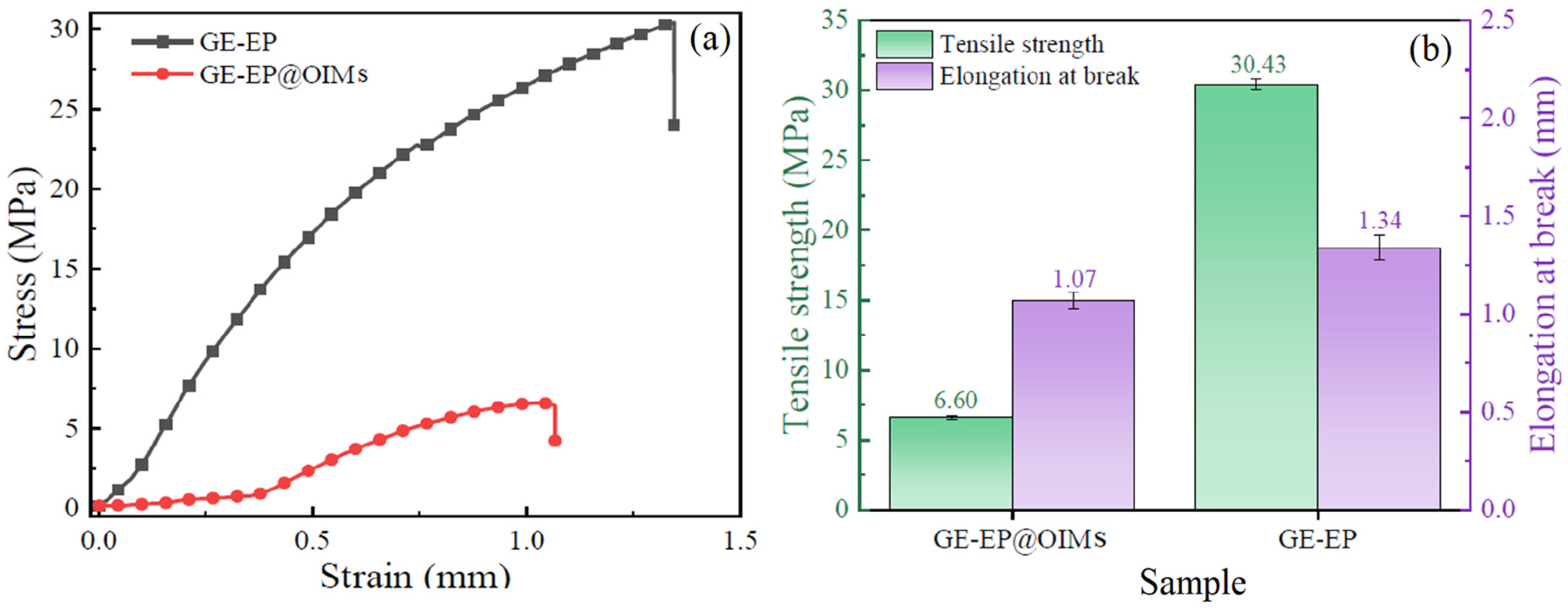
3.1.4. Mechanical Properties of GE-EP@OIMs

Figure 7 presents the stress–strain curve, tensile strength, and breaking elongation of GE-EP and the solid corrosion inhibitor GE-EP@OIMs. The rate of growth in mechanical properties holds paramount significance for solid corrosion inhibitors, as it enables them to endure stresses, preclude the formation of microcracks, and guarantee durable and long-term protection within harsh and pressurized environments. In the absence of an adequate growth rate of mechanical properties, the performance and service life of the inhibitors are substantially impaired when subjected to pressurized and flowing corrosive media. These mechanical properties play a crucial role in averting the occurrence of slow corrosion damage, which, if left unchecked, would otherwise curtail the effective protection period. GE-EP demonstrates remarkably favorable mechanical properties, with a tensile strength of approximately 30.43 MPa.
Subsequent to the loading of the OIM corrosion inhibitor, the tensile strength of the solid corrosion inhibitor GE-EP@OIMs undergoes a significant reduction, attaining a value of approximately 6.60 MPa. The incorporation of OIMs leads to a diminution in the content of adhesives and curing agents, thereby giving rise to a decrease in the number of cross-linked polymer molecular chains. This, in turn, accounts for the observed decline in tensile strength. The breaking elongations of GE-EP and GE-EP@OIMs are measured as 1.34 mm and 1.07 mm, respectively. The similarity in the fracture elongation of GE-EP before and after the loading of the OIM corrosion inhibitor can likely be ascribed to the inherent characteristics of the solid corrosion inhibitor. The presence of the introduced weighting agent, BaSO4, is potentially correlated with this phenomenon. Although the mechanical strength of the solid corrosion inhibitor is inferior to that of GE-EP, it nevertheless satisfies the requisite fluidity criteria for medium- to long-term applications. This assertion is substantiated by the morphological characteristics of GE-EP@OIMs following long-term immersion.

3.2. Inhibitor Releasing Characteristics and Mechanism of OIMs@PAM

3.2.1. Release Behavior of GE-EP@OIMs in Different pH Environment

The release behavior of OIMs from GE-EP@OIMs in NaCl solution was evaluated at 20 °C, 50 °C, and 80 °C. As shown in Figure 8, the OIM release was notably high, with concentrations reaching 313 mg/L, 497 mg/L, and 703 mg/L at 20 °C, 50 °C, and 80 °C, respectively. The accelerated release rate at 80 °C (703 mg/L) promoted rapid inhibitor film formation, as elevated temperatures enhanced molecular mobility, effectively suppressing corrosion in a shorter duration. Over time, the OIM concentration decreased significantly, declining to 9 mg/L, 99 mg/L, and 19 mg/L after 60 days at 20 °C, 50 °C, and 80 °C, respectively. This reduction is attributed to two primary factors: (1) the OIM release pathway progressively extended from the surface to the interior and (2) the diminishing OIM content within GE-EP@OIMs reduced the driving force for release. During the initial 1–30 days, higher temperatures facilitated greater OIM release due to increased thermal motion, enhancing molecular migration through the water-based epoxy resin and curing agent network [32].
Figure 8 depicts the concentration and cumulative release of OIMs from GE-EP@OIMs within a NaCl solution at temperatures of 20 °C, 50 °C, and 80 °C. At the commencement, the release of OIMs from GE-EP@OIMs is exceedingly pronounced, with the OIM concentration reaching 313 mg/L, 497 mg/L, and 703 mg/L at 20 °C, 50 °C, and 80 °C, respectively. At 80 °C, the elevated release rate of OIMs (703 mg/L) expedites the formation of the inhibitor film. This is because the augmented temperature facilitates molecular motion, thereby effectively suppressing corrosion within a brief temporal span. As time progresses, the concentration of OIMs gradually diminishes. After 60 days of immersion at 20 °C, 50 °C, and 80 °C, the OIM concentrations decline to 9 mg/L, 99 mg/L, and 19 mg/L, respectively. The continuous reduction in the released concentration of OIMs can be ascribed to two principal factors: (1) the release pathway of OIMs progressively extends from the surface towards the interior; and (2) the continuous depletion of OIM content within GE-EP@OIMs lessens the driving force for its release. During the initial 1–30 days within the same release period, the concentration of released OIM augments with an increase in temperature. This phenomenon can be attributed to the fact that higher temperatures stimulate the thermal motion of OIMs, which accelerates their migration among the molecular chains constituted by the water-based epoxy resin and the curing agent [32].
The OIM release concentration follows the pattern of 50 °C > 80 °C > 20 °C within the 30–60-day period. This can be attributed to the fact that the cumulative release of OIMs in GE-EP@OIMs reaches 81% in the first 30 days at 80 °C, which leads to a sharp decrease in the residual content of the OIM corrosion inhibitor within the sample, from 34.75% to 6.60%. As shown in Figure 8, the cumulative release of GE-EP@OIMs after immersion in 80 °C, 50 °C, and 20 °C solutions for 60 days is 96%, 86%, and 36%, respectively. After 30 days of immersion in the 20 °C solution, the cumulative release of the sample no longer increases significantly, indicating that the release of GE-EP@OIMs has stopped; GE-EP@OIMs is nearly completely released in both 50 °C and 80 °C environments. In the 50 °C environments, the cumulative release of GE-EP@OIMs continues to increase throughout the entire immersion period (1–60 days), with OIMs being stably released at this temperature. However, in the 80 °C environments, the release rate slows down after 40 days, which can be attributed to the reduction in release kinetics caused by the decreasing residual content of OIMs. The differences in the cumulative release curves at different temperatures suggest that the release mechanisms of GE-EP@OIMs may vary with temperature.
Within the 30–60-day interval, the release concentration of OIMs exhibits a pattern where it is in the order of 50 °C > 80 °C > 20 °C. This phenomenon can be ascribed to the circumstance that the cumulative release of OIMs within GE-EP@OIMs attains 81% during the initial 30 days at 80 °C. This, in turn, leads to a precipitous decline in the residual quantity of the OIM corrosion inhibitor within the specimen, diminishing from 34.75% to 6.60%. As illustrated in Figure 8, upon immersion of GE-EP@OIMs in solutions at 80 °C, 50 °C, and 20 °C for a duration of 60 days, the cumulative release amounts are 96%, 86%, and 36%, respectively. Subsequent to 30 days of immersion in the 20 °C solution, the cumulative release of the sample ceases to exhibit a significant increment, signifying that the release of GE-EP@OIMs has halted, whereas GE-EP@OIMs is nearly entirely released in both the 50 °C and 80 °C environments. In the 50 °C environment, the cumulative release of GE-EP@OIMs persists in augmenting throughout the entire immersion period (ranging from 1 to 60 days), with OIMs being released in a stable manner at this temperature. However, in the 80 °C environment, the release rate decelerates after 40 days, which can be imputed to the attenuation of release kinetics consequent to the diminishing residual content of OIMs. The disparities observed in the cumulative release curves at diverse temperatures imply that the release mechanisms of GE-EP@OIMs might be subject to variation with temperature.

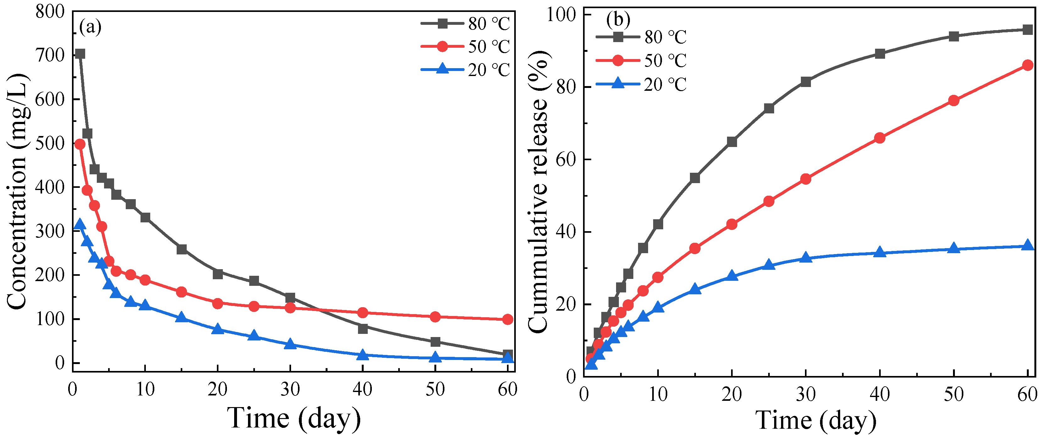
3.2.2. Long-Term Release Behavior of Solid Corrosion Inhibitor at Different Temperatures

The OIM concentration and cumulative release of GE-EP@OIMs in NaCl solution at 20 °C, 50 °C, and 80 °C were studied. At the initial immersion stage, the OIM release from GE-EP@OIMs is very high, with the concentration of OIMs released in 20 °C, 50 °C, and 80 °C environments reaching 313 mg/L, 497 mg/L, and 703 mg/L, respectively. However, the OIM concentration gradually decreases over time as the immersion period increases. After immersing the sample for 60 days in 20 °C, 50 °C, and 80 °C environments, the OIM concentration declines to 9 mg/L, 99 mg/L, and 19 mg/L, respectively.
The continuous decrease in the released concentration of OIMs can be attributed to two main factors: (1) The release path of OIMs gradually shifts from the surface to the interior of the material, and (2) the ongoing reduction in the OIM content within GE-EP@OIMs lowers the driving force for further OIM release. Over the same release time, the OIM release concentration increases with temperature from 20 °C to 80 °C within the first 1–30 days. This may be due to the higher temperatures promoting the thermal motion of OIMs, which accelerates their migration between the molecular chains formed by the water-based epoxy resin and the curing agent [32]. After 30–60 days, the OIM release concentration follows the trend, 50 °C > 80 °C > 20 °C.
This is because the cumulative release of OIMs from GE-EP@OIMs in the 80 °C solution reaches 81% within the first 30 days, leading to a significant decrease in the residual content of the OIM corrosion inhibitor in the sample, which drops from 34.75% to 6.60%. The cumulative release of GE-EP@OIMs after immersion in 80 °C, 50 °C, and 20 °C solutions for 60 days is 96%, 86%, and 36%, respectively. After 30 days of release in the 20 °C solution, the cumulative release no longer increases significantly, indicating that the release of GE-EP@OIMs has stopped, with an effective release time of about 30 days at this temperature. In the 50 °C and 80 °C environments, GE-EP@OIMs is nearly completely released. In the 50 °C environment, the cumulative release continues to increase over the entire immersion period (1–60 days), suggesting stable release of OIMs from GE-EP@OIMs. In contrast, in the 80 °C environment, the release slows down after 40 days, which is attributed to the reduction in release kinetics due to the decreasing residual content of OIMs. The differences in the cumulative release curves at various temperatures suggest that the release mechanisms of the GE-EP@OIMs solid corrosion inhibitor may vary depending on the temperature.

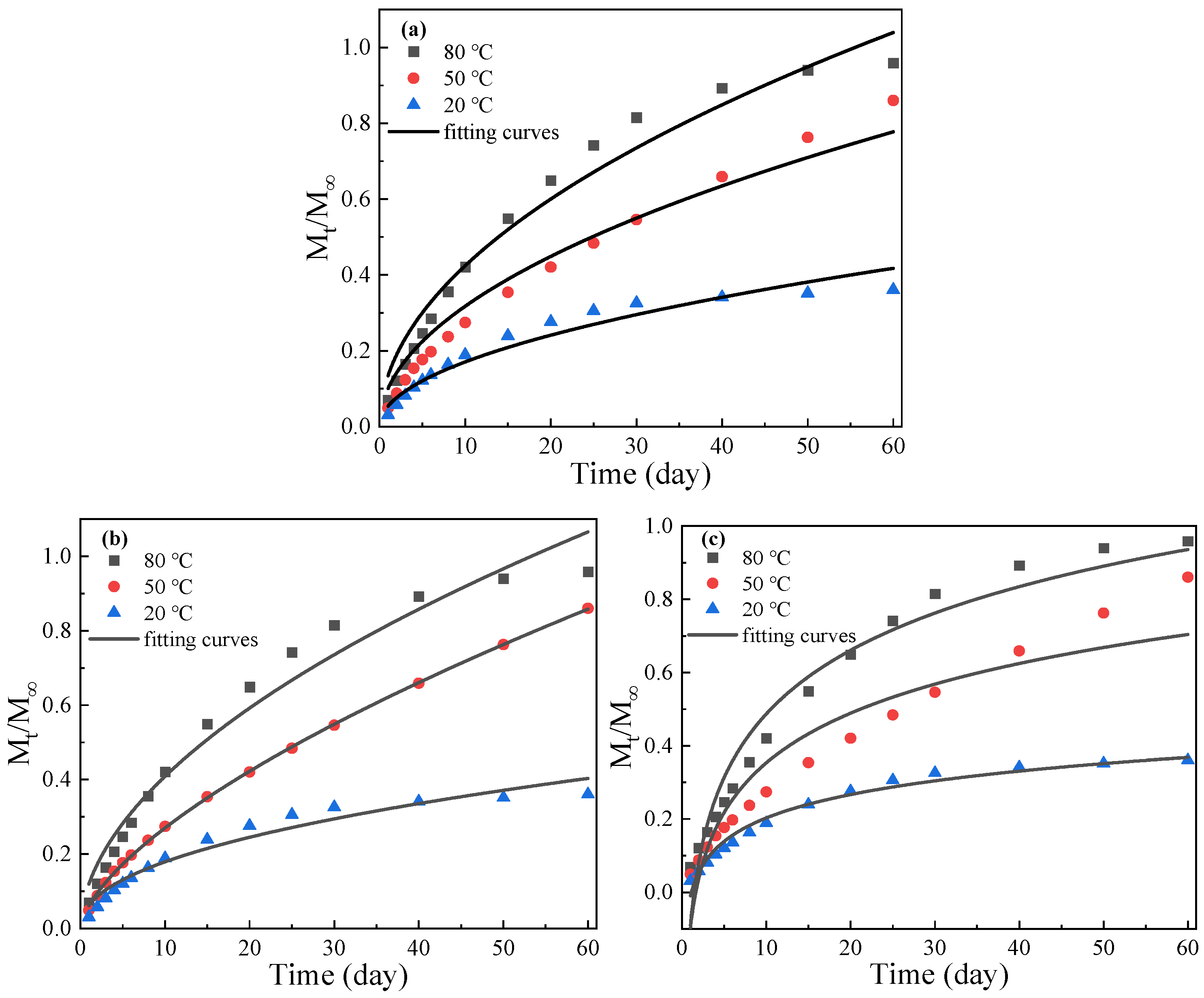
3.2.3. The Release Kinetics of GE-EP@OIMs

The release of the corrosion inhibitor OIM encapsulated in the GE-EP carrier is a complex process influenced by multiple factors. These include the molecular weight, hydrophilicity, and solubility of OIMs; the properties of GE-EP, such as cross-linking, pore size, and degradation; the inhibitor loading method (e.g., in situ coating, adsorption, or cross-linking); and environmental factors like pH, temperature, and ionic strength [33]. Due to this complexity, no single theory can fully explain the release mechanisms. Instead, developing release models based on key factors and fitting cumulative release curves using kinetic models (as shown in Figure 9) provides valuable guidance for predicting performance and enhancing corrosion protection.
Higuchi model [33]:
M t M = K H   t 1 / 2
Korsmeyer–Peppas model [34]:
M t M = k t n
Elovich kinetic model [35,36]:
M t M = 1 β   l n ( α β ) + 1 β   l n t
In each formula, t is the release time, day; Mt and M are the cumulative release of OIMs at time t and infinite time, respectively; α is the initial adsorption rate, β is the desorption constant, n is the constant of the reaction release mechanism, k1, kH, and k are the release rate constants of the response model, respectively. Figure 9 shows the fitting results of GE-EP@OIMs under different kinetic models.
Table 3 shows the release kinetics fitting parameters for each model. From the coefficient of determination (R2) of the fitting results, it can be observed that when a single mathematical model is used to fit the release data of GE-EP@OIMs, the Elovich model performs poorly, with only the release data at 20 °C showing a good fit. The Higuchi model demonstrates good fitting results across the release data, with the lowest R2 values at 20 °C, 50 °C, and 80 °C being greater than 0.95. It is generally accepted that an R2 value greater than 0.7 indicates a strong correlation [37]. The Korsmeyer–Peppas model provides the best overall fitting. According to the Korsmeyer–Peppas model fitting parameters in Table 3, n < 0.45n < 0.45n < 0.45 at 20 °C, and 0.45 ≤ n < 0.89 at 50 °C and 80 °C. This indicates that the release of GE-EP@OIMs follows OIMs in low-temperature solutions, which follows Fick diffusion [34,38], where only the surface or shallow surface material is released. At medium and high temperatures, the release exhibits an “abnormal transport mechanism”, where the release is governed by both Fick diffusion and the properties of the matrix material [39].
From the coefficient of determination (R2) of the fitting results in Table 3, it is evident that the release of GE-EP@OIMs at different temperatures follows different release models. Figure 10 illustrates the release mechanism of GE-EP@OIMs under various temperature conditions. At 20 °C, the release follows the Elovich model (R2 = 0.98), with the release primarily involving OIMs attached to the surface or mixed within the shallow surface layer [33]. This process follows Fick diffusion, and the release rate increases with temperature. This trend is supported by the characteristic parameter α alpha, which increases with temperature [33]. In the 50 °C environment, the release conforms to the Korsmeyer–Peppas model (R2 = 0.99), which indicates an “abnormal transport” mechanism [34].
The release process mainly includes the following: (1) OIMs attached to the surface and shallow surface are dissolved through Fick diffusion; (2) in medium-to-high-temperature solutions, the solution penetrates into the solid corrosion inhibitor via the surface pores, dissolves the gelatin component in GE-EP@OIMs, and exchanges with the internal OIMs [40]; (3) Once the gelatin in GE-EP@OIMs is completely dissolved, the polymer molecular chains in GE-EP@OIMs relax, causing the OIMs to be released and enter the solution. The release mechanism is primarily controlled by Fick diffusion and matrix dissolution. In the 80 °C environment, the release follows the Korsmeyer–Peppas model (R2 = 0.97), with a release process similar to that in the 50 °C solution. However, the release is also influenced by the residual content of OIMs in GE-EP@OIMs. The high-temperature solution accelerates the gelatin dissolution rate, causing the solid corrosion inhibitor’s pore-like transmission channels to form rapidly and continue to develop inward. As the release time progresses, the remaining OIM content in GE-EP@OIMs gradually decreases. Consequently, the release amount of the corrosion inhibitor in high-temperature solutions is largest during the early stage, but the effective release time is shorter than that at 50 °C.

3.2.4. GE-EP@OIMs Morphology After Inhibitor Release

Figure 11 shows the macroscopic morphology of GE-EP@OIMs after immersion in NaCl solutions at 20 °C, 50 °C, and 80 °C for 60 days. The initial GE-EP@OIMs samples were yellow-brown cylindrical solid substances with a diameter and height of 20 mm and an average weight of 15.7377 g. The color of the solid corrosion inhibitor was primarily attributed to the organic corrosion inhibitor components. At 20 °C, the color of the GE-EP@OIMs sample gradually changed from yellow-brown to yellow over time, with no significant color change after 30 days. This indicates that the sample released the corrosion inhibitor slowly at low temperature (20 °C), and the effective release time was approximately 30 days.
At 50 °C, the sample initially faded from yellow-brown to yellow and then turned light yellow after 60 days. This indicates that the solid corrosion inhibitor was released continuously and stably, with an effective release time of approximately 60 days. In the 80 °C solution, the sample released the corrosion inhibitor quickly, fading to light yellow within 50 days. The sample exhibited cracks on the surface, and its mechanical strength decreased. By 60 days, the sample had completely turned pale white, with OIMs almost entirely released, and the cracks on the surface deepened. These macroscopic morphological changes suggest that the sample can rapidly release the OIM corrosion inhibitor in a high-temperature environment, leading to quick and effective corrosion protection for carbon steel in more corrosive conditions. However, the downside is that the effective protection time of the solid corrosion inhibitor is also shortened. This finding is consistent with the cumulative release curve of the solid corrosion inhibitor.
Figure 12 presents the internal SEM image of GE-EP@OIMs after being released in NaCl solutions at 20 °C to 80 °C for 60 days. From the image, it can be observed that in the 20 °C solution, numerous pits appeared in the internal cross-section of the GE-EP@OIMs sample, with gel swelling observed at the edges of the pits. This swelling is due to the gelatin dispersed within the sample continuing to absorb water and swell at low temperatures. In contrast, the gelatin in the sample dissolves in medium- and high-temperature solutions [40]. In the 50 °C environment, the sample exhibits a “honeycomb-like” network structure with numerous micropores and small holes ranging from tens to hundreds of micrometers in diameter. As the gelatin dissolution rate increases with higher solution temperatures, the number of micropores below 100 μm in the 80 °C environment is lower than in the 50 °C environment. However, the number of pores ranging from 100 to 500 μm is significantly higher at 80 °C, and the pores extend deeper into the sample. This facilitates the rapid and extensive release of OIMs from GE-EP@OIMs at high temperatures, although it also reduces the effective release time.

3.3. Corrosion Protection Effect of GE-EP@OIMs in Various pH NaCl Solutions

3.3.1. Weight Loss Measurements

The weight loss experiment was conducted to determine the actual corrosion rate of L80 in NaCl solutions, both with and without GE-EP@OIMs. The corrosion medium was replaced every 24 h to simulate the environment of oilfield-produced water. The test results are presented in Figure 13. When GE-EP@OIMs was not added, the initial corrosion rates (on day 1) at 20 °C, 50 °C, and 80 °C were 0.3759 mm/a, 0.6560 mm/a, and 0.9508 mm/a, respectively. After adding GE-EP@OIMs, the corrosion rates at 20 °C, 50 °C, and 80 °C were reduced to 0.1442 mm/a, 0.3028 mm/a, and 0.4835 mm/a, respectively. This indicates that
  • The corrosion rate of L80 carbon steel is positively correlated with the solution temperature. The higher corrosion rate at 80 °C can be attributed to the fact that elevated temperatures promote the migration of corrosive ions at the electrochemical reaction interface, thereby accelerating the electrochemical reaction process;
  • The corrosion rate of L80 steel decreases gradually over time, eventually stabilizing. According to the NACE-RP0775 standard [41], the long-term (60 days) corrosion rate of L80 steel at 20 °C is highly corroded, while at 50 °C and 80 °C, it is severely corroded. The fact that corrosion rate of L80 carbon steel in various temperature environments exceeds 0.076 mm/a indicates the need for corrosion protection measures in oil-and-gas fields.
As shown in Figure 13, compared to the NaCl solution alone, the corrosion rate of L80 during the immersion period (1–60 days) is consistently lower than 0.1500 mm/a, with the corrosion rate under most conditions even falling below 0.076 mm/a, indicating significant corrosion inhibition. At the same temperature, the corrosion rate of carbon steel gradually increases over time, which is attributed to the daily replacement of the NaCl solution and the gradual reduction of OIMs released by GE-EP@OIMs. The corrosion inhibition rate of GE-EP@OIMs follows different patterns at different temperatures. Specifically, at 20 °C, the inhibition rate gradually decreases, while at 50 °C, the decay is slower, with the inhibition rate remaining above 80% after 60 days of immersion. At 80 °C, the corrosion inhibition rate remains above 80% for the first 40 days but then decreases significantly after that. The corrosion inhibition effect of GE-EP@OIMs is due to the adsorption of the released OIM on the surface of the carbon steel. The corrosion inhibition rate and corrosion rate of L80 in different temperature environments suggest that GE-EP@OIMs is particularly effective for carbon steel corrosion protection in medium-temperature environments, although its effective inhibition time is somewhat reduced in high-temperature environments.

3.3.2. Surface Observation of L80 Steel After Immersion Test

Figure 14 illustrates the microscopic morphology of L80 immersed in NaCl with and without GE-EP@OIMs at different temperatures over a 60-day period. As shown in the figure, L80 without the solid corrosion inhibitor underwent severe corrosion within the 60-day immersion period, with the extent of corrosion increasing as the temperature rose. At 20 °C, the surface of L80 was uniformly corroded, exhibiting a dimple-like morphology with relatively high surface roughness. At 50 °C, a few corrosion pits appeared on the surface of L80, while at 80 °C, the surface was covered with numerous corrosion pits, indicating the most severe corrosion. These corrosion pits are attributed to the Cl ions present in the solution. When the solid corrosion inhibitor was added, the corrosion of the carbon steel was significantly slowed. At 20 °C, traces of sandpaper polishing were still visible, while at 50 °C, the surface became smoother and flatter, with lighter corrosion traces. At 80 °C, small corrosion pits began to appear, and surface roughness slightly increased. The SEM results, aligned with electrochemical and weight loss data, confirm that the GE-EP@OIMs solid corrosion inhibitor demonstrates its ability to provide corrosion protection across a wide temperature range for steel over 60 days at temperature up to 80 °C.
Figure 14 clearly differentiates the microstructures of L80 steel with and without the GE-EP@OIMs inhibitor, highlighting the differences in surface morphology. The sample without the inhibitor shows severe corrosion damage with deep pits, while the inhibited sample exhibits a smoother surface with fewer corrosion defects. This indicates that GE-EP@OIMs effectively reduces localized corrosion by forming a protective barrier, minimizing metal dissolution and pit formation. Additionally, the inhibited sample shows a more uniform surface with fewer polishing scratches affected by corrosion behavior, suggesting that GE-EP@OIMs not only mitigates corrosion initiation but also slows down the propagation of corrosive attack. This protective effect is attributed to the controlled release of OIMs, which adsorbs onto the steel surface, reducing aggressive ion penetration and stabilizing the passive film.
The GE-EP@OIMs solid corrosion inhibitor is particularly well-suited for oilfield applications where corrosion rates are influenced by temperature variations. Due to its temperature-responsive release behavior, it is ideal for downhole tubing, pipelines, and storage tanks exposed to fluctuating thermal environments (20–80 °C). The material’s ability to release inhibitors more rapidly at higher temperatures makes it highly effective in high-temperature, high-salinity, and CO2-rich environments, where conventional inhibitors may degrade or require frequent replenishment. Additionally, its solid-state formulation eliminates the challenges associated with liquid inhibitor injection systems, making it a cost-effective and long-lasting solution for corrosion protection in offshore and onshore oil-and-gas operations.

4. Conclusions

The GE-EP@OIMs solid corrosion inhibitor represents a groundbreaking advancement in corrosion prevention, offering unparalleled performance and addressing critical challenges in the oil-and-gas industry. This study introduces a novel and highly effective solution that combines advanced material science, thermal adaptability, and environmental stewardship to deliver long-term infrastructure protection. The key innovations and advantages of GE-EP@OIMs are as follows:
  • Unprecedented corrosion mitigation performance: This is because GE-EP@OIMs demonstrates exceptional corrosion resistance, particularly at elevated temperatures (50 °C), where it forms a robust protective layer that significantly reduces corrosion rates. This is achieved through its unique chemical composition and morphological properties, which synergistically inhibit corrosion reactions and ensure prolonged structural integrity.
  • Revolutionary solid-state formulation: Unlike conventional liquid inhibitors, GE-EP@OIMs’s solid-state design eliminates challenges associated with uneven dispersion and high-pressure injection systems. This innovation not only simplifies deployment but also reduces operational costs, making it a practical and economically viable solution for field applications.
  • Superior mechanical and thermal resilience: Despite a slight reduction in tensile strength due to OIM incorporation, GE-EP@OIMs maintains excellent mechanical robustness for medium- and long-term use. Its thermal adaptability ensures consistent performance across varying temperatures, a critical feature for oilfield environments. This is enabled by its molecular design, which ensures stability and effectiveness under thermal stress.
  • Environmental and economic sustainability: GE-EP@OIMs is designed with environmental sustainability at its core. By optimizing material usage and reducing reapplication frequency, it minimizes environmental impact and aligns with sustainable development principles. This positions GE-EP@OIMs as a cost-effective and eco-friendly alternative to traditional inhibitors.
  • Novel synthesis and high OIM-loading capacity: The synthesis process, which achieves an OIM-loading capacity of 34.75% (significantly higher than the typical 20%), represents a major breakthrough in material design. This high loading capacity, combined with the temperature-responsive release behavior, ensures targeted and efficient corrosion inhibition in chlorine-rich environments.
The innovative design and superior performance of GE-EP@OIMs position it as a transformative solution for the oil-and-gas sector, with potential applications extending to other industries facing similar corrosion challenges. By addressing the limitations of conventional inhibitors and offering a cost-effective, environmentally sustainable, and highly efficient alternative, GE-EP@OIMs sets a new benchmark in corrosion prevention.

Author Contributions

Y.Z.: Conceptualization, Methodology, Data curation, Writing—original draft. Q.Y.: Writing—review and editing, A.H.K.: Writing—review and editing. B.L.: Methodology, Formal analysis, Data curation, writing—original draft, Writing—review and editing. J.T.: Conceptualization, Methodology, Resources, Writing—review and editing. All authors have read and agreed to the published version of the manuscript.

Funding

This research was funded by [National Natural Science Foundation of China] grant number [Grant No. 52201088].

Institutional Review Board Statement

Not applicable.

Informed Consent Statement

Not applicable.

Data Availability Statement

All raw and processed data necessary for reproducing results in this study can be accessed on reasonable request.

Acknowledgments

The authors would like to express their sincere gratitude to Hailong Zhang, Yingying Wang, and Dan Wang for their valuable contributions to this research. Hailong Zhang from the School of Materials Science and Engineering, Xihua University, provided insightful guidance on material characterization and corrosion analysis, which greatly enhanced the understanding of the inhibitor’s performance. Yingying Wang, from the Key Laboratory of Optoelectronic Chemical Materials and Devices (Ministry of Education), Jianghan University, offered essential expertise in chemical material interactions and analytical methodologies, contributing significantly to the experimental analysis. Dan Wang, from the School of Electrical and Automation Engineering, Changshu Institute of Technology, assisted in data processing and the interpretation of electrochemical measurements, ensuring the accuracy of this study’s findings. Their collective support and collaboration have been instrumental in the successful completion of this work.

Conflicts of Interest

Author Zhao Ying was employed by the company Sichuan Energy Investment Hydrogen Industry Investment Co., Ltd. The remaining authors (Qing Yang, Ali Hussein Khalaf, Bing Lin, and Junlei Tang) declare that the research was conducted in the absence of any commercial or financial relationships that could be construed as a potential conflict of interest.

References

  1. Zhang, S.; Dong, B.; Zhao, D.; Yang, J.; Sun, X.; Yan, L. Corrosion of carbon steel by Pseudomonas stutzeri CQ-Z5 in simulated oilfield water. Bioelectrochemistry 2024, 162, 108846. [Google Scholar]
  2. David, M.; Jasmin, R.; Louis, G. Techno-economic analysis of hybrid solar-assisted geothermal and biomass heating systems in remote subarctic communities (Nunavik, Canada). Energy 2024, 313, 133898. [Google Scholar]
  3. Li, H.; Liu, H.; Zhu, J.; Wang, X. Overview on plant extracts as green corrosion inhibitors in the oil and gas fields. J. Mater. Res. Technol. 2019, 8, 6376–6389. [Google Scholar]
  4. Zhao, L.; Yan, Y.; Yan, X. A semi-empirical model for CO2 erosion-corrosion of carbon steel pipelines in wet gas-solid flow. J. Pet. Sci. Eng. 2021, 200, 108203. [Google Scholar]
  5. Li, L.; Wang, X.; Miao, J.; Aliya, A.; Jing, X.; Ren, N. Carbon neutrality of wastewater treatment: A systematic concept beyond the plant boundary. Environ. Sci. Ecotechnol. 2022, 11, 100180. [Google Scholar] [CrossRef]
  6. Chen, Z.; Abdolreza, F.; Danial, I.; Alireza, R.; Esmaeil, A.; Chen, C. Highly biodegradable corrosion inhibitors derived from sunflower oil for mild steel corrosion in CO2- and H2S-saturated oilfield-produced water. Energy Fuels 2024, 38, 9529–9545. [Google Scholar] [CrossRef]
  7. Hughes, A.E.; Winkler, D.A.; Carr, J.; Lee, P.D. Corrosion inhibition, inhibitor environments, and the role of machine learning. Corros. Mater. Degrad. 2022, 3, 672–693. [Google Scholar] [CrossRef]
  8. Zhang, L.; Ge, L.; He, G.; Tian, Z.; Huang, J. Tuning the linkers in polymer-based cathodes to realize high sulfur content and high-performance potassium–sulfur batteries. J. Phys. Chem. C 2021, 125, 28790–28801. [Google Scholar]
  9. Chen, C.; Reniers, G. Chemical industry in China: The current status, safety problems, and pathways for future sustainable development. Saf. Sci. 2020, 128, 104741. [Google Scholar]
  10. Jones, R.; Al Zubaidi, I.; Alzughaibi, M. Crude glycerol as an innovative corrosion inhibitor. Appl. Syst. Innov. 2018, 1, 12. [Google Scholar] [CrossRef]
  11. Pojtanabuntoeng, T.; Kinsella, B.; Ehsani, H. Assessment of corrosion control by pH neutralisation in the presence of glycol at low temperature. Corros. Sci. 2017, 128, 94–103. [Google Scholar]
  12. Zhang, Y.; Yu, M.; Chen, C.; Li, S.; Liu, J. Self-healing coatings based on stimuli-responsive release of corrosion inhibitors: A review. Front. Mater. 2022, 8, 795397. [Google Scholar]
  13. Zuo, J.; Dong, B.; Xing, F.; Luo, C.; Zhan, J.; Wang, L. Preparation and behavior of sustained-release corrosion inhibitor microcapsules by centrifugation-coating method. Powder Technol. 2021, 389, 32–39. [Google Scholar]
  14. Wang, T.; Wang, W.; Feng, H.; Sun, T.; Ma, C.; Cao, L. Photothermal nanofiller-based polydimethylsiloxane anticorrosion coating with multiple cyclic self-healing and long-term self-healing performance. Chem. Eng. J. 2022, 446, 137077. [Google Scholar] [CrossRef]
  15. Tian, Z.; Li, S.; Chen, Y.; Zhang, L.; An, Z. Self-healing coating with a controllable release of corrosion inhibitors by using multifunctional zinc oxide quantum dots as valves. ACS Appl. Mater. Interfaces 2022, 14, 47188–47197. [Google Scholar]
  16. Zhang, D.; Ren, B.; Zhang, Y.; Xu, L.; Huang, Q.; He, Y.; Li, X.; Wu, J.; Yang, J.; Chen, Q.; et al. From design to applications of stimuli-responsive hydrogel strain sensors. J. Mater. Chem. B 2020, 8, 3171–3191. [Google Scholar]
  17. Xing, Z.; Li, Z.; Lu, H. Self-assembled topological transition via intra-and inter-chain coupled binding in physical hydrogel towards mechanical toughening. Polymer 2021, 235, 124268. [Google Scholar]
  18. Li, C.; Zhao, X.; Meng, C.; Zhang, T.; Sun, S.; Hu, S. Application of hollow mesoporous organosilica nanoparticles as pH and redox double stimuli-responsive nanocontainers in the controlled release of corrosion inhibitors. Prog. Org. Coat. 2021, 159, 106437. [Google Scholar]
  19. Ren, Y.; Qi, X.; He, Y.; Peng, Z.; Yang, H.; Liu, X. Green inhibitor-loaded functional halloysite nanotubes modified coatings for improving corrosion protection of carbon steel. Mater. Today Commun. 2024, 38, 108231. [Google Scholar]
  20. GBT 27761-2011; Test Method for Weight Loss and Residual Amount of Thermogravimetric Analyzer. Standards Press of China: Beijing, China, 2011.
  21. GBT 1040; Determination of Tensile Properties of Plastics. Standards Press of China: Beijing, China, 2006.
  22. GB/T 16545-2015; Corrosion of Metals and Alloys—Removal of Corrosion Products from Corrosion Samples. Standardization Administration of China: Beijing, China, 2015.
  23. Zhang, Z.; Zhao, Y.; Gong, Q.; Li, Z.; Li, J. MOFs for CO2 capture and separation from flue gas mixtures: The effect of multifunctional sites on their adsorption capacity and selectivity. Chem. Commun. 2013, 49, 653–661. [Google Scholar] [CrossRef]
  24. Aayisha, S.; Renuga Devi, T.S.; Janani, S.; Muthu, S.; Raja, M.; Sevvanthi, S. DFT, molecular docking and experimental FT-IR, FT-Raman, NMR inquisitions on “4-chloro-N-(4,5-dihydro-1H-imidazol-2-yl)-6-methoxy-2-methylpyrimidin-5-amine”: Alpha-2-imidazoline receptor agonist antihypertensive agent. J. Mol. Struct. 2019, 1186, 468–481. [Google Scholar] [CrossRef]
  25. Yang, Q.; Lin, B.; Tang, J.; Wang, Y.; Zheng, H.; Zhang, H.; Zhang, Y. A pH-Controlled Solid Inhibitor Based on PAM Hydrogel for Steel Corrosion Protection in Wide Range pH NaCl Medium. Molecules 2023, 28, 1314. [Google Scholar] [CrossRef] [PubMed]
  26. Arukalam, I.O.; Madu, I.O.; Ishidi, E.Y. High performance characteristics of Lupinus arboreus gum extract as self-healing and corrosion inhibition agent in epoxy-based coating. Prog. Org. Coat. 2021, 151, 106095. [Google Scholar]
  27. Qiu, C.; Luo, J.; Ling, Y.; Lu, Z.; Ni, L.; Chen, Y.; Liang, M. Thermal Degradation Behavior and Mechanism of Organosilicon Modified Epoxy Resin. Macromol. Chem. Phys. 2022, 223, 2200164. [Google Scholar]
  28. Correia, D.M.; Padrão, J.; Rodrigues, L.R.; Dourado, F.; Lanceros-Méndez, S.; Sencadas, V. Thermal and hydrolytic degradation of electrospun fish gelatin membranes. Polym. Test. 2013, 32, 995–1000. [Google Scholar]
  29. Barreto, P.L.M.; Pires, A.T.N.; Soldi, V. Thermal degradation of edible films based on milk proteins and gelatin in inert atmosphere. Polym. Degrad. Stab. 2003, 79, 147–152. [Google Scholar]
  30. Gou, S.; Luo, S.; Liu, T.; Xia, H.; Jing, D.; Zhang, Q.; Guo, Q. Thermally stable imidazoline-based sulfonate copolymers for enhanced oil recovery. RSC Adv. 2015, 5, 85165–85173. [Google Scholar]
  31. Wang, L.; Zhang, C.; Xie, H.; Xia, H.; Jing, D.; Zhang, Q.; Li, S.; Li, Z.; Guo, Q. Calcium alginate gel capsules loaded with inhibitor for corrosion protection of downhole tube in oilfields. Corros. Sci. 2015, 90, 296–304. [Google Scholar] [CrossRef]
  32. Zhu, Y.; Wang, H.; Tang, J. Molecular dynamics simulation and experimental investigation on the synergistic mechanism and synergistic effect of oleic acid imidazoline and l-cysteine corrosion inhibitors. Corros. Sci. 2021, 179, 108819. [Google Scholar]
  33. Williams, G.; Geary, S.; McMurray, H.N. Smart release corrosion inhibitor pigments based on organic ion-exchange resins. Corros. Sci. 2012, 57, 139–147. [Google Scholar]
  34. Wen, J.; Lei, J.; Chen, J.; Gou, J.; Li, Y.; Li, L. An intelligent coating based on pH-sensitive hybrid hydrogel for corrosion protection of mild steel. Chem. Eng. J. 2020, 392, 123742. [Google Scholar] [CrossRef]
  35. Imanieh, I.; Afshar, A. Corrosion protection of aluminum by smart coatings containing layered double hydroxide (LDH) nanocontainers. J. Mater. Res. Technol. 2019, 8, 3004–3023. [Google Scholar]
  36. El Achaby, M.; Fayoud, N.; Figueroa-Espinoza, M.C.; Aboulkas, A. New highly hydrated cellulose microfibrils with a tendril helical morphology extracted from agro-waste material: Application to removal of dyes from waste water. RSC Adv. 2018, 8, 5212–5224. [Google Scholar] [PubMed]
  37. Koutsoulas, C.; Pippa, N.; Demetzos, C.; Zabka, M. Preparation of liposomal nanoparticles incorporating terbinafine in vitro drug release studies. J. Nanosci. Nanotechnol. 2014, 14, 4529–4533. [Google Scholar] [CrossRef]
  38. Lynch, I.; Dawson, K.A. Release of model compounds from “plum-pudding”-type gels composed of microgel particles randomly dispersed in a gel matrix. J. Phys. Chem. B 2004, 108, 10893–10898. [Google Scholar]
  39. Wu, Y.; Duan, Y.; Qiu, J.; Gao, X.; Ma, H. A pH-responsive intelligent coating based on composite CaCO3 microspheres for long-term corrosion protection of Q235 carbon steel. Appl. Surf. Sci. 2022, 578, 151980. [Google Scholar]
  40. Steyaert, I.; Rahier, H.; Van Vlierberghe, S.; Olijve, J.; De Clerck, K. Gelatin nanofibers: Analysis of triple helix dissociation temperature and cold-water-solubility. Food Hydrocoll. 2016, 57, 200–208. [Google Scholar]
  41. NACE RP0775-2005; Preparation, Installation, Analysis, and Interpretation of Corrosion Coupons in Oilfield Operations. NACE International: Houston, TX, USA, 2005.
Figure 1. Schematic diagram of the preparation of GE-EP@OIMs solid corrosion inhibitors.
Applsci 15 03964 g001
Figure 2. (a): UV-vis spectra for different OIM solutions of known concentration; (b): the fitted standard curve of OIMs.
Applsci 15 03964 g002
Figure 3. SEM Micrographs of GE-EP@OIMs. (a) Surface morphology without OIMs after vacuum drying. (b) Internal morphology without OIMs after vacuum drying. (c) Surface morphology loaded with OIMs after vacuum drying, orange for 200 μm and blue for 100 μm diameters ranging (d) Internal morphology loaded with OIMs after vacuum drying.
Applsci 15 03964 g003
Figure 4. EDS of GE-EP@OIMs: (a) Surface EDS showing elemental distribution. (b) Interior EDS showing elemental distribution.
Applsci 15 03964 g004
Figure 5. FTIR spectra of pure OIM, GE-EP, and GE-EP@OIMs.
Applsci 15 03964 g005
Figure 6. TGA curves of pure OIMs, GE-EP, and GE-EP@OIMs.
Applsci 15 03964 g006
Figure 7. (a) Tensile stress–strain curve of GE-EP and GE-EP@OIMs after vacuum-drying for 72 h at 45 °C; (b) the values of the tensile strength and the elongation at break of OIMs and OIMs@PAM.
Applsci 15 03964 g007
Figure 8. The concentration (a) and the cumulative release (b) of OIMs from GE-EP@OIMs in different temperature.
Applsci 15 03964 g008
Figure 9. Plots of the three kinetic models for the release of OIMs from GE-EP@OIMs: (a): Higuchi model, (b): Korsmeyer–Peppas model, and (c): Elovich model.
Applsci 15 03964 g009
Figure 10. Release mechanism of GE-EP@OIMs under different temperature environments.
Applsci 15 03964 g010
Figure 11. Macroscopic morphology of GE-EP@OIMs immersed in NaCl solution at 20 °C, 50 °C, and 80 °C for different time periods.
Applsci 15 03964 g011
Figure 12. The internal SEM images of GE-EP@OIMs after releasing for 60 days in different temperature solutions. (a): 20 °C, (b): 50 °C, and (c): 80 °C.
Applsci 15 03964 g012
Figure 13. Corrosion rate and inhibition efficiency of L80 in different temperature solutions of 3.5 wt.% NaCl with and without GE-EP@OIMs: (a) without GE-EP@OIMs and (b) with GE-EP@OIMs.
Applsci 15 03964 g013
Figure 14. Microstructure of L80 after immersion in NaCl solutions at different temperatures for 60 days without or with GE-EP@OIMs added; (ac) are NaCl solutions at 20 °C, 50 °C, and 80 °C, respectively; (df) are NaCl solutions at 20 °C, 50 °C, and 80 °C, respectively.
Applsci 15 03964 g014
Table 1. Main elements and contents of L80.
ElementCSiMnPSCrNiMoFe
L800.360.451.00.030.0040.950.040.38Balance
Table 2. Table summarizing measurements.
Time (Days)Number of MeasurementsMass Before (mg)Mass After (mg)Weight Loss (mg)Corrosion Rate (mm/y)
13120.543120.2140.3290.5464
53120.214119.8760.3380.8078
103119.876119.5320.3440.4330
203119.532119.190.3420.7149
303119.19118.850.340.8456
403118.85118.510.340.6661
503118.51118.170.340.4582
603118.17117.830.340.4929
Table 3. Kinetic model fitting parameters for corrosion inhibitor release.
HiguchiKorsmeyer–PeppasElovich
ModelR2kHR2nkR2βα
0.970.13420.970.53450.11940.953.98860.1749
0.960.10040.990.64490.06120.895.11000.1191
0.950.05390.950.44310.06310.9810.83340.0832
Disclaimer/Publisher’s Note: The statements, opinions and data contained in all publications are solely those of the individual author(s) and contributor(s) and not of MDPI and/or the editor(s). MDPI and/or the editor(s) disclaim responsibility for any injury to people or property resulting from any ideas, methods, instructions or products referred to in the content.

