Review

Review of Passive Flow Control Methods for Compressor Linear Cascades

by
Oana Dumitrescu
*,
Emilia-Georgiana Prisăcariu
* and
Valeriu Drăgan
Romanian Research and Development Institute for Gas Turbines COMOTI, 061126 Bucharest, Romania
*
Authors to whom correspondence should be addressed.
Appl. Sci. 2025, 15(7), 4040; https://doi.org/10.3390/app15074040
Submission received: 3 March 2025 / Revised: 31 March 2025 / Accepted: 3 April 2025 / Published: 7 April 2025
(This article belongs to the Special Issue Feature Review Papers in Mechanical Engineering, 2nd Edition)

Abstract

:
This paper reviews the evolution of flow control methods for bladed linear cascades, focusing on passive techniques like riblets, grooves, vortex generators (VGs), and blade slots, which have proven effective in reducing drag, suppressing flow separation, and enhancing stability. The review outlines key historical developments that have improved flow efficiency and reduced losses in cascades. Bio-inspired designs, including riblets and grooves, help stabilize the boundary layer, reduce loss coefficients, and improve flow turning, which is vital for controlling drag and secondary flow effects. Vortex generators, fences, and slotted wingtips enhance stall margins and suppress corner separation, improving performance under off-design conditions. These methods are optimized based on aerodynamic parameters such as Reynolds number and boundary layer characteristics, offering substantial efficiency gains in high-performance compressors. Advancements in computational tools, like high-fidelity simulations and optimization techniques, have provided deeper insights into complex flow phenomena, including turbulence and vortex dynamics. Despite these advancements, challenges remain in fully optimizing these methods for diverse operating conditions and ensuring their practical application. This review highlights promising strategies for improving flow control efficiency and robustness, contributing to the design of next-generation turbomachinery.

1. Introduction

Modern gas turbine engines are designed with higher pressure ratios, which require larger compressors to meet the performance demands. To improve the power-to-weight ratio, the design often focuses on minimizing the number of compressor stages by increasing blade loading. While this approach can lead to improvements in efficiency, it also comes with the downside of increased aerodynamic losses. These losses are typically a result of profile loss, secondary flow loss and tip-leakage loss.
Secondary flow losses, in particular, are caused by vortices that form due to pressure variations across the compressor blades. One notable source of these vortices is the formation of corner vortices, which can lead to corner separation. This separation reduces the ability of the compressor to maintain static pressure rise, which in turn can lead to flow blockage, unstable operation and in extreme cases, surge [1]. The factors that influence the onset of separation are multifaceted and include the blade profile, incidence angle, turbulence, Reynolds and Mach numbers, the rotational speed and surface roughness. Understanding and mitigating these factors are essential in ensuring optimal performance while minimizing losses and maintaining engine stability.
By manipulating the flow around blade rows, it is possible to achieve objectives such as improved lift, drag reduction, vibration suppression and noise minimization. These improvements are particularly important in applications like gas turbines, where even modest efficiency gains can significantly reduce fuel consumption and emissions. Linear cascade studies are useful for studying how adjacent blades interact in a controlled setting, helping to understand flow behaviours like boundary layer separation and wake interactions.
Flow control techniques are generally classified into passive, active and reactive methods, with the latter adapting dynamically to changing flow conditions. Active flow control requires external energy sources and typically involves techniques like synthetic and continuous jets [2], injection vortex generators [3,4], plasma [5,6], fluidic actuators [7,8] and surface suction/injection [9,10]. These methods are often more effective than passive techniques, particularly in managing unsteady flow separation in corner regions.
In contrast, passive flow control relies on geometric alterations that influence the flow without the need for additional energy input. While passive methods cannot be toggled on and off like active systems, their simplicity, adaptability, and cost-effectiveness [11,12] make them widely adopted in flow control applications. These methods are especially beneficial in scenarios requiring lift augmentation, drag reduction, reduced tip leakage and separation control. However, they may result in additional losses when unnecessary. Recent studies have focused on passive techniques such as three-dimensional blade designs [13,14], tandem blades [15], fences and grooves [16,17] and vortex generators [18,19], all of which enhance aerodynamic performance by mitigating endwall flow separation.
This review seeks to evaluate and synthesize current methodologies, drawing on experimental findings and computational studies of passive flow control methods for linear cascades. By examining their respective advantages, limitations, and applicability, the review aims to guide the development of more efficient turbomachinery designs. Furthermore, it aims to clarify the mechanisms through which these flow control methods affect flow behaviour in linear cascades, ultimately contributing to the creation of more efficient and reliable turbomachinery.

2. Chronological Evolution of Linear Cascade

Research on linear cascades in turbomachinery has evolved significantly over the decades, with foundational studies before 1970 laying the groundwork for understanding flow behaviours, loss mechanisms and the efficiency of cascade designs. Early investigations primarily focused on two-dimensional cascade flows, establishing fundamental principles that would guide subsequent advancements in compressor blade optimization.
The principle of linear cascades can be considered to have emerged during World War II and developed afterward. Locating the exact primary publication can be challenging, with most experimental campaigns on linear cascades attributed to the National Advisory Committee for Aeronautics (NACA) [20] and disseminated in a series of publications called Wartime Reports [21]. One of these reports can be considered the first to describe experimental work on a linear cascade; titled “Preliminary Experimental Investigation of Airfoils in Cascade” [22], it focused on cascade arrangements of airfoils and examined aerodynamic performance factors like pressure distribution and airflow through the blades. This study became a critical early reference for cascade testing methods in compressors and turbines. It represented one of the first structured approaches to studying airfoil behaviour in cascades and provided data crucial to advancing blade designs in turbomachinery. The rudimentary experimental setup can be observed in Figure 1a. Subsequent technical reports on linear cascades followed. Another report from the same series, titled “Systematic Two-Dimensional Cascade Tests of NACA-65 Series Compressor Blades at Low Speed” [23], describes the 5-inch cascade installation at Langley, identifying it as a fully functioning system built in the 1940s and improved in the early 1950s. The Langley cascade is pictured in Figure 1b.
By 1955, theoretical studies had identified three primary vorticity components in non-uniform fluid flow through turbine or compressor blade cascades: distributed secondary circulation due to flow curvature, trailing shed circulation resulting from spanwise variations along the blade, and trailing filament circulation caused by vortex stretching in blade wakes [25]. These principles applied to both cascades and isolated airfoil flows, providing a framework for subsequent research. That same year, Lieblein [26] correlated experimental cascade data to explore variations in performance, proposing simplified rules for predicting losses and angles. However, the work also highlighted the need for further investigations into high Mach number effects and three-dimensional influences. Building on this foundation, Lieblein and Roudebush [23] developed theoretical loss relations based on wake characteristics, improving the prediction of loss coefficients and influencing blade design methods.
In 1965, Lindley [27] explored the impact of boundary layer characteristics on cascade performance, highlighting differences between laminar and turbulent flows. The study revealed the role of clearance leakage and wall effects in creating complex three-dimensional flow behaviours and identified corner separation on the low-pressure surface of blades, worsened at high angles of attack due to adverse pressure gradients. During the same period, a study on stall propagation in circular cascades proposed a theoretical model to predict stall cell velocity and conditions for cell splitting [28]. In 1957, Schlichting [29] analyzed compressible flows in high-speed cascade wind tunnels, examining the effects of Mach and Reynolds numbers. Concurrently, research on low-speed cascades established correlations between loss and velocity diffusion, showing that higher diffusion ratios increased stall risk by thickening wake momentum [30]. Herrig et al. [31] emphasized the role of dynamic loading parameters, such as blade camber and angle of attack, in optimizing compressor design.
From 1958 to 1963, research refined the understanding of flow patterns and loss mechanisms, focusing on wall effects and stall zones [32,33]. In 1962, theoretical work predicted stall zones at blade corners, which experimental studies later validated by showing stall growth along blade roots and tips [34]. By 1963, investigations into secondary flow patterns in axial compressors promoted design improvements that reduced secondary flow losses [35]. Research through the 1970s further explored geometric effects on flow, revealing that aspect ratio had a significant impact. High aspect ratios increased deflection near stall, while low aspect ratios caused flow contraction at the centerline [36]. A 1978 study on wall boundary layers indicated that inviscid flow adjustments could dominate boundary layer behaviour through cascades, emphasizing the interplay between boundary layers and cascade aerodynamics [37].
Advancements in the 1980s and 1990s built on these foundational insights. A 1982 study introduced a method for computing secondary flows in cascades, incorporating Bernoulli surface rotation effects. While significant distortions were observed near endwalls, the impact on downstream flow was minimal [38]. In 1985, investigations using rotating pressure probes highlighted the complexity of vortex flows near rotor casing and end-wall-tip interactions. The studies revealed that flow unsteadiness distorted probe data, but dynamic calibration successfully corrected these inaccuracies [39]. Additional research during this period focused on the effects of increased blade loading, which often led to corner separation. In severe cases, this corner separation extended into full-span separation on the rotor. For second-stage stators, high blade loading caused significant growth in corner separation, with blockage reaching nearly 40% and extending to 70% of the blade span [40,41].
These trends persisted into the 1990s, with researchers confirming that increased compressor loading amplified both the spread and intensity of corner separation. Studies from this era demonstrated how these effects could limit performance and highlighted the importance of advanced design techniques to mitigate separation [42,43,44].
The 1990s marked significant advancements in compressor blade design and cascade performance, with a strong focus on passive control methods. In 1993, hot-wire anemometry and pressure measurements revealed that narrow crenulations on blade edges enhanced wake mixing and reduced pressure losses more effectively than larger crenulations. This finding provided a practical approach to improving cascade efficiency and highlighted the potential of subtle blade-edge modifications [45]. Numerical studies from the same year demonstrated the benefits of grooved endwalls, which energized leakage flows and reduced blockage, offering a promising technique for stall suppression in compressor cascades [46]. Complementary research on tip leakage vortices showed intensified vorticity near the leading edge, which decayed downstream, further revealing the complex nature of leakage flow interactions [47].
In 1994, investigations into NACA 65-1810 blades with varying tip clearances revealed that larger clearances reduced the mixing efficiency of leakage flows, particularly when downstream mixing was incomplete [48]. These findings underscored the importance of optimizing blade and endwall geometries to mitigate losses and enhance overall performance. Later in the decade, a 1998 study using laser-Doppler velocimetry documented unsteady stalling phenomena in controlled-diffusion blades. This research identified regions of continuous and intermittent reverse flow, refining the understanding of blade surface interactions under challenging flow conditions [49].
These studies laid the groundwork for passive flow control strategies, including blade-edge modifications, grooved endwalls, and tip clearance optimization. Subsequent research explored advanced aerodynamic features, such as blade sweep and dihedral stacking lines, to address secondary flows and corner stall more effectively.
In 1998, researchers investigated the effects of sweep and dihedral stacking lines on linear compressor cascades. Forward-swept blades were found to reduce secondary flows and corner stall by generating vortices that supplied high-energy fluid to the endwall region. Meanwhile, positive dihedral blades alleviated endwall loading and mitigated secondary flow effects. These findings highlighted how modifications to blade geometry and stacking lines could enhance flow stability and reduce losses, adding a new dimension to aerodynamic optimization [50].
As research entered the 2000s, focus shifted towards addressing critical issues like suction-side flow separation, which contributes to stall flutter and high-cycle fatigue. A 2000 study on transonic fan airfoils demonstrated that cascade solidity and Mach number significantly influenced the extent of suction-side separation. Higher solidity in supersonic conditions improved flow attachment by moving the shock downstream, while lower solidity in subsonic conditions exacerbated separation. Computational simulations validated these findings, offering insights into optimizing cascade solidity to mitigate flow separation and enhance performance in high-speed environments [51].
In recent decades, new approaches for designing linear cascades have emerged, with a focus on improving efficiency and stability in compressors, as well as advancing instrumentation and flow visualization techniques. Figure 2 presents the University of Tokyo and DRL solution for a linear cascade, along with the associated instrumentation used for analysis.
In gas turbine systems operating on the Brayton cycle, the compressor is a major consumer of power, accounting for approximately 40–50% of the total power produced by the turbine. This significant energy demand directly impacts overall efficiency and fuel consumption [54]. Implementing flow control methods has proven effective in enhancing compressor performance, leading to improved efficiency and fuel savings. In aviation gas turbines, techniques such as vortex generators, tip treatments and optimized blade designs help reduce compressor work input, thereby increasing thermal efficiency. Similarly, in power generation turbines, methods like lean premixed combustion and film cooling contribute to efficiency gains by optimizing airflow through the compressor and turbine stages, indirectly reducing fuel consumption.
Research indicates that optimizing compressor pressure ratios and mass flow rates significantly impacts net work output and thermal efficiency [55]. Effective flow control strategies for mitigating axial compressor fouling can further reduce specific fuel consumption [56]. Additionally, advanced control schemes regulating compressor differential pressure and turbine exhaust temperature have been shown to enhance energy efficiency, with fuel consumption reductions of up to 8.96% in certain load ranges [57].
By addressing inefficiencies in compressor performance, flow control techniques play a crucial role in improving gas turbine efficiency and achieving measurable fuel savings. Furthermore, the paper presents flow control solutions, along with the results obtained by tackling different aerodynamic challenges that could be encountered during the development of turbomachinery.

2.1. Passive Control Methods

Since the 1970s, compressor airfoils for high Mach number applications have predominantly utilized circular arc design methodologies. These include Double Circular Arc (DCA) airfoils, which feature suction and pressure surfaces defined by two distinct radii, and Multiple Circular Arc (MCA) airfoils, which employ several arcs. The German Aerospace Center (DLR) has played a leading role in turbomachinery development since the 1970s, with a pivotal 1976 study examining transonic cascade performance influenced by the Axial Velocity Density Ratio. This research expanded to include L030 rotor investigations using DCA and MCA airfoils, with these early studies relying on empirical data and correlations to analyze transonic cascades [58,59,60,61]. By the late 1980s, significant design advancements were made, including the introduction of viscous–inviscid interaction algorithms for manual cascade optimization and inverse design methodologies that achieved prescribed velocity distributions. These advancements facilitated the development of controlled diffusion airfoil designs, optimizing flow characteristics across the blade surfaces.
In the realm of computational fluid dynamics (CFD), studies on axial flow compressor solidity demonstrated that decreasing solidity led to increased losses and reduced stall margins, with no identifiable minimum-loss condition. Comparing these results with Lieblein’s correlations highlighted the impact of inlet Mach numbers and variations in pitch-to-chord ratios on losses [62]. While the Baldwin-Lomax model presented limitations, two-equation models proved to be more reliable, emphasizing the importance of experimental validation for optimizing compressor designs with respect to both efficiency and weight reduction.
Optimization algorithms have revolutionized the design of blades, particularly under transonic conditions. A 2023 study focused on designing a compressor cascade for DLR’s Transonic Cascade Wind Tunnel. By using optimization techniques with AutoOpti and TRACE solvers to improve efficiency across both the design and working ranges, the study achieved a remarkable 24% improvement in efficiency [63]. These findings provide valuable insights into blade optimization under complex transonic flows, marking a significant step forward in compressor design optimization.
Research on boundary layer behaviour in single and tandem airfoils has also highlighted the significant effects of Reynolds numbers, turbulence intensities, and blade designs on performance. Tandem configurations, in particular, showed interdependent boundary layers, with thicker layers developing under higher turbulence conditions [64]. These results emphasize the importance of designing airfoils tailored to varying operating conditions, with particular attention to turbulence and flow behaviour.
Furthermore, the passive control methods are categorized based on their primary mechanisms of action.

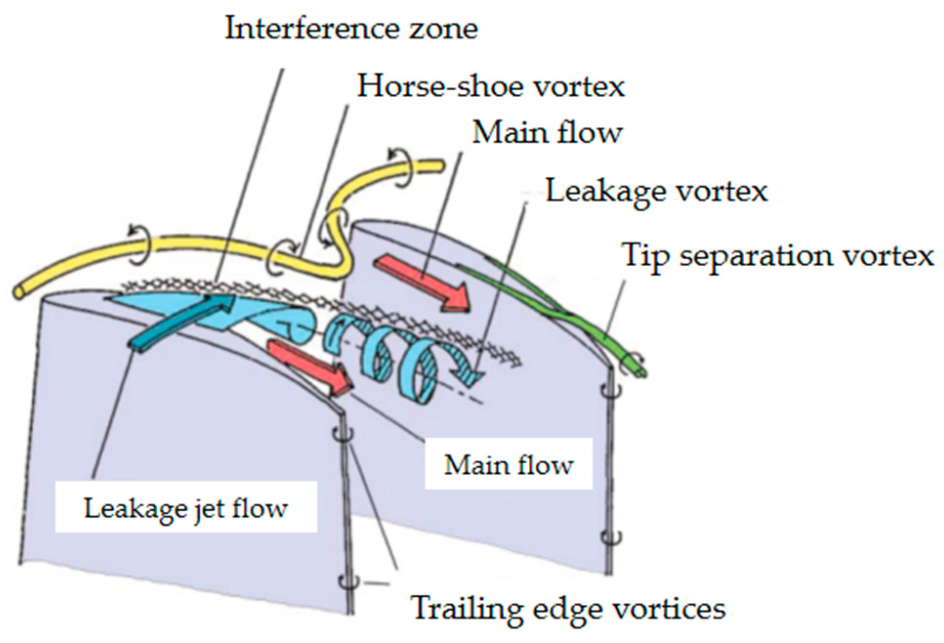
2.1.1. Tip Clearance and Loss Reduction

A.
Tip clearance flows—control leakage flows to reduce loss at blade tips
Tip clearance flows in high-pressure compressor stages significantly affect aerodynamic efficiency and operational stability, primarily through leakage losses and blockage near the blade tip, which reduces compressor performance and stall margin. Figure 3 illustrates the flow phenomena developed near the tip region of a blade, highlighting the impact of tip clearance on performance. Proper management of this clearance is essential to optimize performance.
Research has consistently shown that increasing tip clearance results in a deterioration of performance. Moore’s study revealed that the impact on compressor performance is particularly noticeable from 70% of the blade span to the tip, with larger clearances worsening aerodynamic performance and reducing stall margin [65].
Figure 3. Flow phenomena at the tip region of the blades [66].
Applsci 15 04040 g003
Further studies have investigated the impact of large tip clearances (up to 6% of the chord) on compressor performance, showing that losses stabilized beyond a 4% clearance, with blade loading increasing above 2%. This was attributed to the presence of a strong tip clearance vortex, which remained constrained, suggesting a delicate balance between optimizing performance and maintaining mechanical robustness [67]. A direct numerical simulation study highlighted the role of free-stream turbulence in the transition to turbulence and boundary layer attachment. Increased turbulence was shown to improve boundary layer attachment but delayed reattachment on the suction surface after separation, emphasizing the complex dynamics involved in managing boundary layers in compressor flows [68].
Studies using Doppler Global Velocimetry and hot-wire anemometry examined the dual role of tip clearance vortices in compressor cascades. While caused localized flow separation at the suction-side trailing edge, it also reduced wake pressure losses, extending their beneficial effects up to 20% of the blade height [69,70]. This demonstrated the importance of understanding three-dimensional interactions to optimize flow control and reduce losses. Tip-leakage flow in a linear compressor cascade and a one-stage shrouded pump rotor was analyzed using Reynolds-averaged Navier–Stokes equations. The study examined flow through non-rotating blade passages with varying tip clearances (0% and 2% of chord) and investigated the complex interactions between tip-clearance and passage vortices, highlighting the formation of the tip-leakage vortex and its effects on flow behaviour [71].
Additional research explored the effects of increasing tip clearance (from 1% to 3% of the span), revealing that larger clearances reduced wall losses and strengthened the tip vortex structure. The study also noted how variations in inlet angles influenced boundary layer performance, with changes affecting separation points, turbulence intensity, and downstream flow patterns. These findings reinforced the importance of managing both tip clearance and inlet angles to minimize losses and optimize secondary flow interactions [72,73]. Non-axisymmetric endwall contouring emerged as a promising technique to improve cascade efficiency by reducing total pressure losses and enhancing outflow uniformity in highly loaded cascades. However, further wind tunnel testing was recommended to validate these results for multi-row configurations and downstream blade interactions [74]. Additionally, casing aspiration schemes were explored for controlling the tip leakage vortex (TLV). Optimal casing aspiration reduced the total loss coefficient by 4.7% at 0° and 5.9% at 4° incidence angles when the aspiration flow rate was around 0.7%. The mechanism’s effectiveness depended on the placement along the blade chord, with aspiration at the TLV onset point reducing the TLV size and mixing distance, while downstream placement potentially increased mixing losses [75]. The influence of incidence angles on secondary flow losses was also studied, with higher angles increasing these losses, emphasizing the need for optimized designs [76].
Tip leakage flow control through blade tip suction schemes showed that positioning suction downstream of the TLV reduced the total loss coefficient by 13.6%, significantly improving aerodynamic performance and reducing cascade inefficiencies [77]. Studies on shock-induced flow separation in a transonic compressor cascade at an inlet Mach number of 1.21 revealed that air-jet vortex generators (AJVGs) could reduce the separation region size, though turbulence or surface roughness had a more significant impact on reducing the separation region [78]. Similarly, aeroelastic damping research emphasized the importance of minimizing tip gaps to improve compressor performance stability by reducing unsteady pressure reflections from the tailboard [79]. Recent LES studies revealed that tripped boundary layers created stronger, wider tip leakage vortices, offering deeper insights into managing tip-leakage flows and their acoustic behaviour [80]. A study on transonic buffet flow dynamics in a 2-D compressor blade model found that shock oscillations exhibited feedback between upstream and downstream regions, challenging previous models of shock-buffet behaviour [81].
Tip clearance plays a crucial role in compressor cascade performance, with increased clearances generally leading to increased vortex strength and leakage losses. Effective management of this clearance, through techniques like endwall suction or non-axisymmetric contouring, can significantly improve aerodynamic performance. Additionally, understanding the complex interactions between tip leakage and secondary flows is vital for optimizing compressor efficiency.
B.
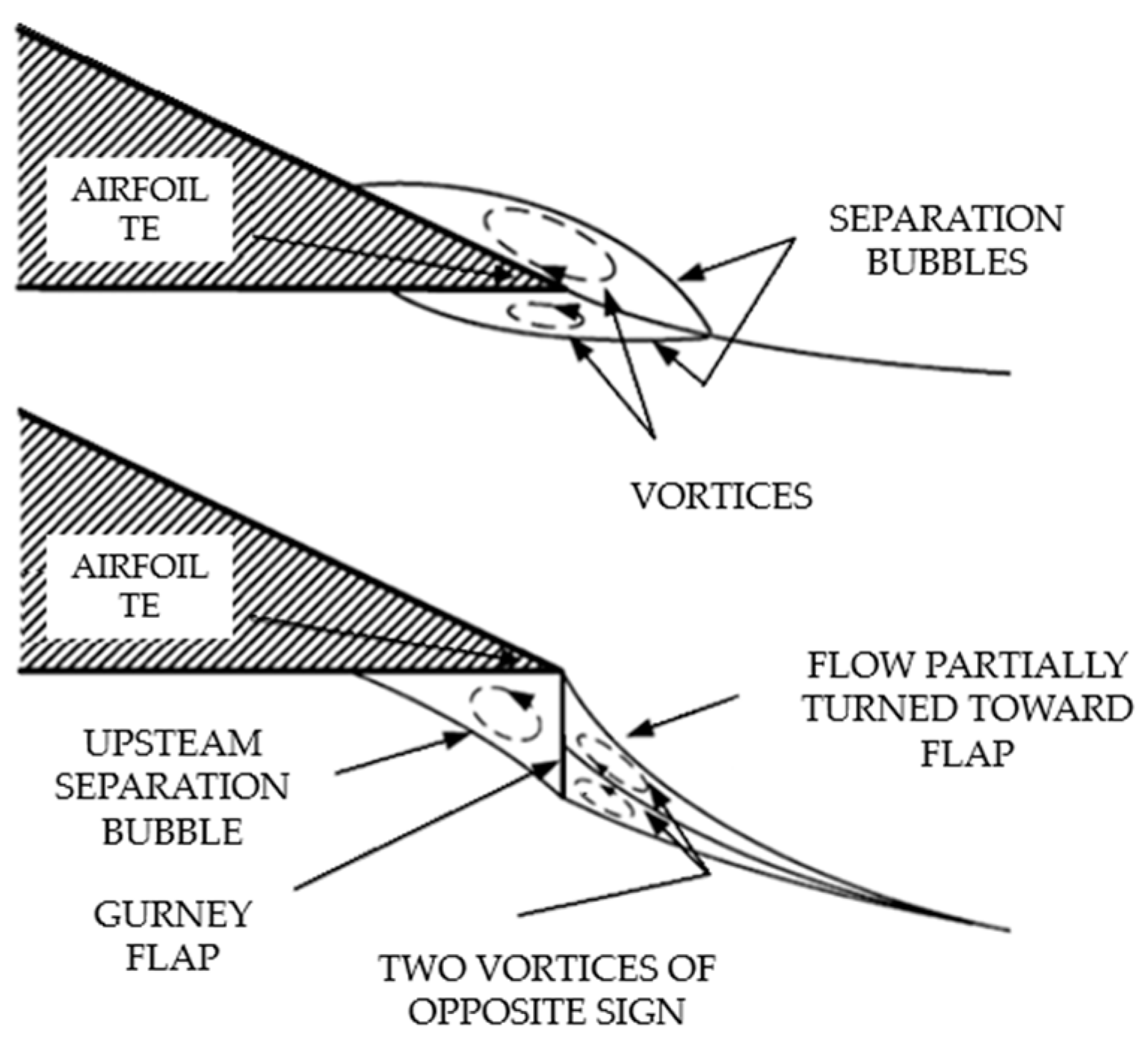
Gourney flaps—increase lift and modify wake structures to enhance efficiency
The development of flow control techniques, especially the application of Gurney flaps, has shown great promise in managing laminar separation in both compressor and turbine cascades. Over several decades, these studies have contributed to notable improvements in flow control, while also underscoring the importance of carefully balancing performance gains with the aerodynamic penalties that may arise.
In a 2003 study, Gurney flaps were first tested on turbine blades, specifically Langston blade shapes, which experienced laminar separation at low Reynolds numbers (Re = 28,000 and Re = 65,000). Small Gurney flaps, ranging from 0.6% to 2.7% of the axial chord, were positioned near the trailing edge of the pressure surface. These modifications resulted in accelerated flow, effectively eliminating separation bubbles and enhancing lift. However, the increased lift came with the trade-off of larger wakes. The study suggested employing semi-passive deployment strategies, allowing the flap to retract at higher Reynolds numbers, thus optimizing performance across different operating conditions [82].
Building on these findings, a 2006 study investigated a NACA 65-(12)10 compressor cascade operating at a lower Reynolds number (Re = 16,000), utilizing tuft flow visualization in a water table facility. The study found that a Gurney flap with a 2% chord length could energize the flow and delay stall at higher incoming flow angles. However, it also pointed out increased boundary layer losses, which were not fully quantified, suggesting that further research was necessary to better understand the trade-off between flow control benefits and aerodynamic penalties [83].
At the same time, blade design innovations explored the integration of winglets at the tips of compressor blades to tackle tip leakage vortex issues. Suction-side winglets were found to effectively weaken the tip leakage vortex, thereby reducing total pressure losses, particularly at minimal tip clearances [84].
The use of Gurney flaps was revisited as a semi-passive flow control technique in highly loaded linear compressor cascades. These trailing-edge devices delayed boundary layer separation and improved flow turning, enhancing aerodynamic performance in stall conditions, although they also led to higher total pressure losses. To mitigate these losses, semi-passive deployment strategies were recommended, enabling selective engagement of the Gurney flaps depending on specific operating conditions. A study on NACA 65(15)10 blades showed that a flap placed perpendicular to the chord at the trailing edge, with a height of 2% of the chord length, improved flow turning but also increased total loss [85].
Additionally, the aerodynamic performance of NACA 0010 cascades with Gurney flaps was examined at three stagger angles (45°, 90°, and 135°). The 2% chord-length flap, inclined at 45°, significantly enhanced lift across all configurations. However, it was found to reduce aerodynamic efficiency at a stagger angle of 45°, while providing substantial benefits at 135°. Streamline visualizations revealed counter-rotating vortex pairs behind the Gurney flap, with their decay rate influenced by both the stagger angle and the angle of attack, demonstrating a complex interaction between flow dynamics and flap configuration [86].
Figure 4 illustrates the flow near the trailing edge of a conventional airfoil at a moderate lift coefficient, emphasizing the separation bubbles formed both with and without a Gurney flap.
These studies underscore the versatility and promise of Gurney flaps as flow control devices, though also highlight the ongoing need for optimization strategies and deeper understanding of their trade-offs in aerodynamic performance.

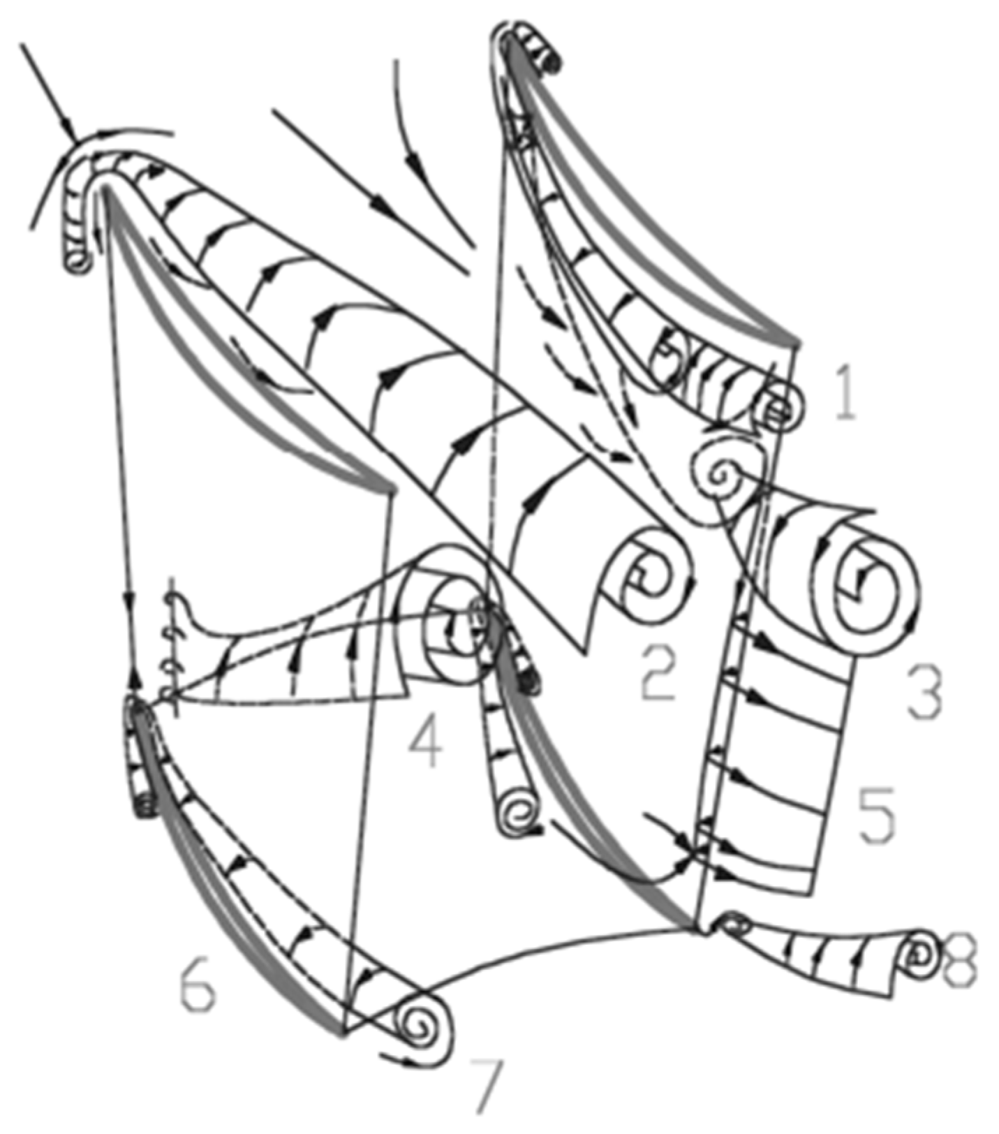
2.1.2. Secondary Flow and Separation Control

A.
Vortex-generators—Generate streamwise vortices to control secondary flows.
Recent studies have significantly advanced our understanding of vortex dynamics in compressor cascades, leading to enhanced aerodynamic performance and reduced flow losses. For instance, an experimental study on vortex generators applied to a highly loaded compressor cascade demonstrated a reduction of up to 9% in total pressure losses with minimal effect on static pressure rise [88]. This finding highlights the potential of VGs to extend the stall range and influence cascade deflection, providing valuable insights for future compressor designs, particularly in nonaxisymmetric endwalls and blade modifications.
Research on nonconventional vortex generators, such as doublet and wishbone designs, has shown their ability to delay or eliminate separation on the blade suction surface and endwall. Although these designs caused a slight increase in pressure loss, it significantly reduced skin friction, with the doublet and wishbone vortex generators achieving a 46% and 32% reduction in skin friction at the bottom endwall, respectively [89]. Moreover, a synthetic flow control approach, combining vortex generators with slot jets, has proven effective in improving cascade performance by suppressing endwall crossflow and deflecting passage vortices. This combined strategy reduced secondary flow development and enhanced flow uniformity, offering a powerful tool for flow control in compressors [90].
Micro-vortex generators (MVGs) have also been explored as a means of improving high-load compressor cascade performance. Various configurations of MVGs, such as rectangular, curved rectangular, trapezoidal, and curved trapezoidal designs, helped suppress secondary flow development and delayed stall onset. Notably, the curved trapezoidal VGCT configuration achieved a 9.36% reduction in total pressure loss at stall conditions, with the maximum secondary flow loss reduction reaching 34.6% [91].
Further investigations into vortex dynamics, particularly with the use of curved blades, have revealed a 28.29% reduction in flow losses during corner stall. The introduction of curved blades weakened vortex intensity and redistributed low-energy fluid, improving compressor performance and mitigating adverse flow phenomena like stall [92]. Additionally, combining MVGs with boundary layer suction has proven effective in reducing secondary flows, delaying stall onset, and improving flow distribution, especially under high-load conditions [93].
Vortex generators inspired by dragonfly wing veins, when placed at the leading edge of the suction surface, have also shown promise. These designs helped shift the separation point downstream and reduced corner separation, achieving a reduction in flow losses by 10.3% when optimally positioned [94]. A comprehensive study on VG placement, stagger angle, height, and length further revealed that VGs are most effective when placed in high-velocity differential regions, contributing to more efficient designs and a deeper understanding of their impact on compressor performance [95].
Figure 5 presents the vortex structure formed in a compressor diffuser near the casing and near the hub suction side corners, offering a visual representation of the flow dynamics discussed above. The figure illustrates the following types of vortex structures: horse-shoe vortices on the suction and pressure sides of the upper half-height (1 and 2), a passage vortex (2), a concentrated shedding vortex (3), a passage-induced vortex (4), a trailing-edge flake shedding vortex (5), horse-shoe vortices on the suction and pressure sides of the lower half-height (6 and 7), and a trailing vortex (8).
B.
End-wall and corner separation control—shape modification to reduce losses at critical regions
The optimization of endwall designs has become a crucial strategy for reducing secondary flows and losses in compressor cascades, thus enhancing overall compressor efficiency. Various design modifications have been explored to improve aerodynamic performance. A landmark study in 2004 on bulb-shaped endwalls demonstrated their ability to amplify horseshoe vortices, counteracting passage vortices and achieving a 28% reduction in secondary losses. Further investigations found that co-rotating vortices, generated by fillet modifications, reduced losses, while blunt fillets exacerbated them, emphasizing the need for precise geometric optimization [97].
Non-axisymmetric endwall profiling (PEWs) has also been widely studied for axial compressors. Research from Cambridge University demonstrated that PEWs improved exit flow by reducing losses and under-turning in the secondary flow region, while also suppressing stator hub corner stall in a six-stage high-pressure compressor by redirecting the low-momentum core of the horseshoe vortex. Although PEWs showed limited benefits in modern compressors with advanced 3-D blades, it still offered promise when combined with 3-D blade shaping to increase aerodynamic loading and efficiency [98]. CFD simulations supported these findings, demonstrating enhanced cross-flow on the endwall that aids in secondary flow migration and corner stall control. Further studies on stator endwall profiling in transonic compressors revealed a 1.8% increase in efficiency, although reverse flow at the casing increased under off-design conditions, highlighting the need for further optimization [99].
In 2009, another numerical study confirmed that optimizing the stator hub endwall led to a 1.8% efficiency increase by reducing hub-corner stall. However, it also induced greater reverse flow at the casing, which became more pronounced at off-design conditions. Optimizing the shroud endwall improved off-design performance, yielding a 0.03% efficiency increase at the design point. These results demonstrated that endwall profiling, when applied alongside 3-D blading in high-loaded stator compressors, could effectively control separation and improve component characteristics [100]. Research in 2011 focused on combining non-axisymmetric profiled endwalls with boundary layer fences, which reduced cross-flow and delayed corner separation, resulting in an 8% reduction in cascade losses at the design point, as supported by high-fidelity RANS simulations [101].
Advancements in 2015 and 2016 highlighted the potential of non-axisymmetric endwall contouring to reduce secondary flow losses and mitigate corner stall. Optimized designs resulted in significant reductions in secondary flows, improving cascade efficiency and addressing challenges posed by three-dimensional flow interactions. Studies using Wall-Resolved Large Eddy Simulation (LES) provided detailed insights into corner separation phenomena in a linear compressor cascade. These simulations, validated against experimental data, accurately predicted static pressure coefficients, total pressure losses and velocity profiles. The results emphasized the role of turbulent structures, such as aperiodic vortex shedding, and turbulent anisotropy in affecting flow conditions at corner separation points. LES proved effective in capturing unsteady corner separation and guiding the development of separation control methods, providing more detailed results than RANS, which, while useful for parametric studies, tended to overestimate corner separation [102,103,104,105]. Figure 6 presents a topology of corner separation near the trailing edge of a axial compressor blade.
Optimization tools like DLR AutoOpti [106] and the TRACE RANS [107] solver in 2017 showed that non-axisymmetric endwall contours in highly loaded compressor cascades reduced total pressure losses and improved outflow homogeneity. These findings reaffirmed the effectiveness of non-axisymmetric shaping, though additional tests were needed to validate multi-row interactions and downstream effects [102]. In the same year, the optimization of end slots on NACA65 cascade blades using the NSGA2 algorithm resulted in a 10% reduction in total pressure loss at a 4° incidence angle, significantly enhancing cascade performance by reducing sensitivity to incidence variations [108].
Wei’s [109] study on three-dimensional separation at the juncture of the endwall and blade corner region aimed to use prediction parameters to gain an early insight into the flow field behaviour within the cascade, prior to conducting experimental and numerical analyses. The equivalent diffusion factor DFeq Equation (1) [33] is employed to predict separation at mid-span. The experimental DFeq values are derived from the five-hole pressure probe measurements. It is observed that the flow at mid-span does not separate at i = 4° but does separate at i = 6°, as shown in Figure 7, which presents both experimental and numerical results of the parameter. Another factor was earlier, proposed by Lei [110], the diffusion parameter D Equation (2) [111] to predict the size and intensity of the corner stall. The size and strength of the corner stall increase with incidence. According to this prediction, large separation regions on both the suction side and the endwall occur when i > 8.3°.
D F e q = c o s β 2 c o s β 1 1.12 + α i i * 1.43 + 0.61 c o s 2 β 1 σ t a n β 2 t a n β 1
D = 1 c o s i + γ + φ / 2 c o s γ φ / 2 2 i + φ η σ
where i is the incidence, i* is the optimum incidence, σ is the solidity, β1 and β2 are upstream flow angle and downstream flow angle, γ stagger angle, φ blade camber angle, Δη additional turning angle due to skewed incoming endwall boundary layer. The limitation of DFeq is that it is unreliable when i < i*.
Further studies in 2017 investigated the use of end-wall vortex generators (VGs) for controlling secondary flows in high-turning compressor cascades. These VG systems resulted in notable improvements, such as a 21.5% reduction in secondary flow losses at a 60° camber angle, along with additional improvements at other incidence angles, including a 13.2% reduction at −5° and 32.5% at +5° incidence [112]. Another innovative approach involved a self-supplied jet separation control method, which introduced an arc slot connecting the pressure and suction sides to induce a jet flow that mitigated suction side separation. Experimental results showed a 21.9% decrease in total loss and an increase in the flow turning angle by 2.1°, significantly enhancing the stability margin and improving the operating margin by at least 3° with respect to the incidence angle [113]. The use of vortex generator jets on endwalls also demonstrated improved aerodynamic performance in a high subsonic compressor cascade, with reductions in total pressure loss by up to 14.6% at optimal incidence angles [114].
In a combined flow control study, the integration of a blade slot and VG in a high-load compressor cascade resulted in a 30.9% reduction in total pressure loss, a 2° increase in flow turning, and a 69.9% enhancement in the pressure coefficient. The slot reattached suction side separations, while the VG suppressed passage vortex and corner separation, contributing to better flow structure and reduced sensitivity to incidence, thus improving overall cascade efficiency [115]. In the domain of passive control, the use of arced diverging-converging slots on blades showed remarkable results, including a 40.5% reduction in total pressure loss and a 20.3% increase in flow turning angle at positive incidence angles [116]. The positioning of these slots between 50% and 80% of the blade chord optimized performance by reducing backflow zones and enhancing flow stability near the endwalls, achieving a 16.41% reduction in total loss coefficient and a 4° increase in flow turning [117].
Figure 8 illustrates the effect of the fence device on endwall secondary flow by showing fluid particles, coloured according to total pressure, as it moves from the cascade inlet. The endwall fence significantly impacts the secondary flow structure and aerodynamic performance of a highly loaded compressor cascade. The optimal fence reduces flow losses by blocking crossflow, weakening passage and corner vortices, and improving pressure distribution. A fence with 0.5 mm thickness, 10% of the inflow boundary layer height, and 75% of the blade chord length reduces total loss by 1.55% and simplifies the vortex structure, leading to more uniform outflow conditions [118].
An endwall suction scheme was also tested for high-load compressor cascades at large incidence angles. The suction scheme delayed the roll-up of the tip leakage vortex (TLV), weakened its intensity and reduced leakage losses. However, at high suction flow rates (0.7%), the scheme caused an increase in boundary layer separation losses in the lower blade span region, worsening the overall flow field below 42% span. Despite reducing leakage losses, the total pressure loss coefficient increased by 5.7% at incidence angles of ±8°, rendering the scheme ineffective under the studied conditions [120].
By 2022, L-shaped grooves emerged as a novel loss control technique, yielding a 17.9% reduction in total pressure loss and a 5.53% increase in static pressure rise under design conditions. This method also proved beneficial under off-design conditions, further enhancing compressor efficiency [121]. Studies on combined flow control configurations demonstrated that integrating end-wall suction slots and whole-span slots reduced total pressure loss by 38.4% and improved turning angles by 3.1%, offering superior performance over slotted configurations, especially for designs requiring higher thrust-to-weight ratios [122]. Additionally, the use of vane slots in centrifugal compressors reduced the total pressure loss coefficient by 65.6% and improved deviation angles by 2.3° at higher incidence angles [123]. In similar studies on NACA 65-009 blades with slots grooved from the pressure side to the suction side, a 33% reduction in total pressure loss and a 17.6% increase in blade loading were achieved at positive incidence angles, demonstrating the effectiveness of passive control methods for enhancing compressor efficiency [124].
Most recently, research confirmed that non-axisymmetric endwall contours could further reduce losses by redirecting low-momentum fluid, showing improvements across a wide range of operating conditions. However, further investigation is required to optimize these designs for specific blade characteristics and operational environments [125].
C.
Fences and grooves—Mitigate corner separation and secondary flow losses.
Passive flow control techniques in compressor cascades, such as slotted blades, have gained attention for their potential to improve aerodynamic performance and reduce losses. The use of slotted NACA 65(18)10 blades in a highly loaded linear compressor cascade focused on optimizing slot placement between the minimum pressure and separation points. The findings revealed that this configuration reduced the loss coefficient by up to 28.3%, prevented boundary layer detachment, and improved performance. A 50° difference in turning angle between slotted and unslotted configurations further emphasized the impact of slot placement. Additional research is needed to explore the effects of slot convergence, number, and spanwise extent in three-dimensional contexts [126].
Building upon this, the study extends to the impact of aerodynamic parameters and blade fillets on corner separation and cascade performance. It highlights that high pitch-chord ratio blades are prone to stalling under increased loading, yet slot configurations can mitigate corner separation, thus enabling a reduction in the number of blades required for a more favourable thrust-weight ratio. The study also identifies the effect of aspect ratio on performance, noting that high aspect ratio blades tend to stall more easily, while low aspect ratio blades exhibit more pronounced three-dimensional flow and corner separation. The use of slot configurations consistently improved corner separation and overall cascade performance across all aspect ratios, with the PVD cascade showing notable improvements near the endwall despite certain shifts [121].
Another critical factor influencing aerodynamic performance in compressor cascades is the incidence angle. Studies have demonstrated that negative incidence angles exacerbate disturbances on the pressure surface and amplify wake formation, while positive incidence angles can mitigate these effects, leading to improved flow stability and reduced disruptions [127]. These findings underscore the importance of optimizing incidence angles to enhance compressor efficiency.
Further research in 2017 introduced a combined flow control strategy that integrated mid-span boundary layer suction with positively bowed blades. This dual approach effectively reduced trailing-edge separation and corner separation near the endwall, achieving a substantial 31.4% reduction in cascade losses [128]. The versatility of this strategy, which performs well across a range of operational conditions, underscores its potential for improving compressor performance under varied flow regimes.
An experimental study focused on the suppression of three-dimensional corner separation in a high-speed compressor cascade further validated the efficacy of blade end slots as a passive control method. Experiments conducted across a range of incidence angles at Ma = 0.59 revealed that blade end slots effectively suppressed 3D corner separation, expanding the operational range and reducing total pressure loss by up to 39.4% [129]. The study highlighted the mechanism by which blade end slots generate high-momentum jet flows, induced by pressure differences between the blade’s pressure and suction surfaces. These jet flows enhance downstream flow momentum in the corner region, suppress secondary vortex structures, and promote more two-dimensional flow in the mid-span region. Additional studies in 2019 compared the performance of blade end slots and full-span slots for controlling corner separation. The results indicated that blade end slots performed better at lower incidence angles, while full-span slots were more effective at higher incidence angles [130]. Despite these differences, blade end slots provided a more balanced performance across various operational conditions, making them highly suitable for practical compressor designs.
Regarding groove height, its impact on corner separation suppression followed a non-linear trend. As the groove height increased, the ability to reduce separation initially improved, but then began to decline. At a groove height of 4% of the blade height, the flow loss in the cascade was reduced by 14.42% [131].
Overall, fences and grooves have demonstrated significant potential in mitigating corner separation and reducing aerodynamic losses in compressor cascades. While their effectiveness depends on specific design parameters such as slot placement and groove height, these passive control methods offer a viable approach for improving compressor efficiency.

2.1.3. Passive Flow Control via Surface Modifications

The role of boundary layer behaviour in compressor performance has been a focus of research, with studies on controlled diffusion airfoils (CDA) showing that higher turbulence levels move the transition point upstream. In 2014, suction at 70% of the axial chord improved boundary layer conditions and reduced passage total pressure losses [132,133]. Variations in inlet flow angle, Mach number, and Reynolds number (450,000 to 900,000) significantly affected total pressure loss. Shock-induced transition occurred over separated flow at lower Reynolds numbers, and without separation at higher Reynolds numbers [134]. Further research into controlling corner flow in a highly loaded axial compressor cascade has shown that endwall suction, particularly using a pitchwise slot, provides the best performance across various incidence angles. Compound suction configurations, combining a spanwise blade slot with a pitchwise endwall slot, proved even more effective, achieving a total pressure loss reduction of up to 39.4% at 7° incidence. For accurately capturing the complex 3D separations in the transonic cascade, the Reynolds Stress Model (RSM) was identified as the most suitable turbulence model [135]. The impact of blade end slots and full-span slots on corner separation was also evaluated. Slotted profiles suppressed separation, particularly at high incidence angles, with blade end slots outperforming full-span slots by reducing mixing losses at mid-span [136].
In 2021, rotor-stator interactions were found to significantly influence secondary flow patterns and boundary layer transitions. Shock Control Bump (SCB) technology was applied to transonic compressor blades, effectively reducing aerodynamic losses and improving efficiency at peak speeds [137,138]. Figure 9 presents the geometry of this type of shock control bump, where the initial position of the SCB structure is crucial to suppress loss of stagnation pressure in blade passages. The SCB structure is composed of ramp, crest plateau, and tail sections, connected smoothly as a curve with third-order continuity using fourth-order spline fitting [139].
Further investigations on shock wave–boundary layer interactions using perforated plates and porous wall designs revealed that these methods reduced shock intensity and improved efficiency while managing flow separation [139,140]. Figure 10 illustrates a perforated airfoil (main and secondary blades) used to suppress the shock waves of a centrifugal compressor diffuser.
Additionally, porous bleed holes in transonic compressor cascades resulted in up to a 75% reduction in total pressure losses by delaying flow separation through better boundary layer control [141]. A study on bleed pressure in transonic compressors demonstrated that lower bleed pressure ratios notably reduced pressure losses. The changes in shock wave structure led to the creation of favourable pressure gradients, which in turn enhanced boundary layer stability [142]. Furthermore, an investigation into shock-wave/boundary-layer interactions in transonic compressor cascades showed that increasing Mach numbers had a substantial effect on shock patterns. The presence of separation bubbles and shock oscillations resulted in significant fluctuations in the pressure field [143].

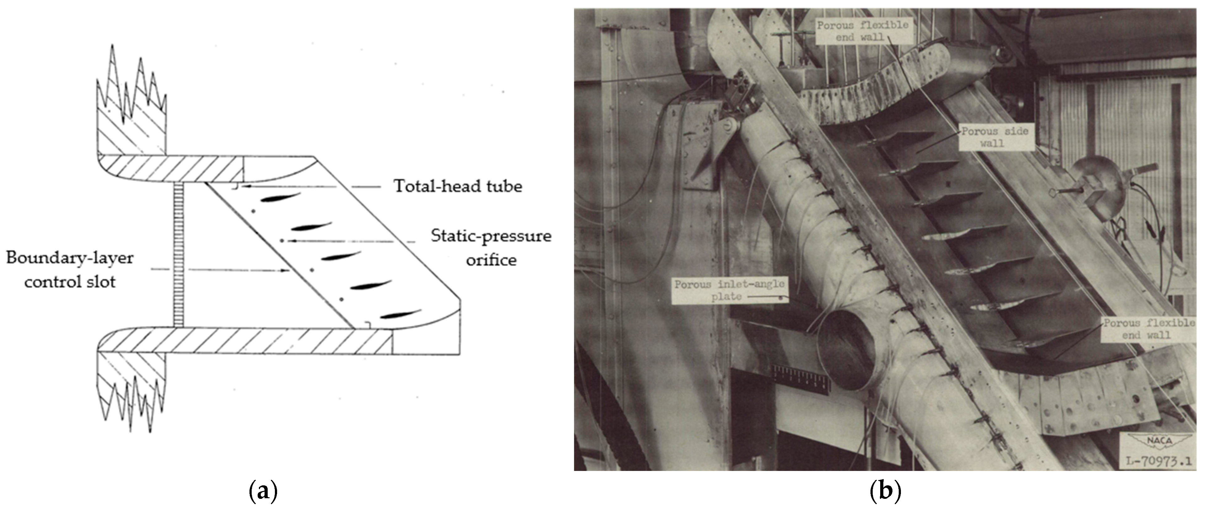
2.1.4. Boundary Layer Control

Recent advancements in compressor cascade performance have been significantly driven by innovative flow control strategies, particularly bio-inspired designs and passive control methods, which aim to enhance aerodynamic efficiency. Among these advancements, slanting riblets, inspired by the microscopic patterns found on birds’ secondary flight feathers, have shown great promise in reducing drag. Liu et al. [144] demonstrated a 16.8% reduction in pressure loss when using slanting riblets in a linear cascade. Similarly, herringbone riblets have also been studied for their drag-reducing potential. These riblets improve flow turning angles and reduce pressure loss by up to 36.4% at low Reynolds numbers by suppressing flow separation and energizing the boundary layer [145].
In addition to riblet designs, bio-inspired structures, such as endwall bionic chambers modelled after dragonfly wings, have proven effective in reducing aerodynamic losses. These chambers optimize cascade incidence angles and enhance turbulent kinetic energy (TKE), leading to a 9.43% reduction in total pressure loss and an 8.35% increase in static pressure when placed between 25% and 50% of the chord length [146]. Sharkskin-inspired riblets, which align with the flow direction, have been shown to improve compressor blade performance by advancing boundary layer transition and reducing separation flow regions [147]. Furthermore, slotted wingtips, inspired by bald eagle flight dynamics, offer up to 80% greater lift compared to conventional designs. However, their effectiveness hinges on balancing flap frequency to avoid destabilizing the flow in practical turbomachinery applications [148].
Research on endwall effects, which significantly influence compressor blade performance, has led to improved blade designs. A promising combination of bowed blades and leading-edge strake blades (LESB) achieved substantial aerodynamic improvements, with the optimized bowed LESB cascade reducing total pressure loss by 59.7%, while maintaining static pressure rise and diffusion factor [149]. Overall, bio-inspired designs, particularly riblets, have proven highly effective in reducing drag and improving turbomachinery performance. Riblets, as a passive treatment, can reduce shear stress by up to 13.2%, enhancing flow mixing and suppressing near-wall turbulence, thus lowering drag [150]. In gas turbine compressors, riblets promote earlier transition to turbulent flow, reducing skin friction by up to 18%, even under variable conditions [151]. Additionally, bio-inspired leading edge designs help suppress separation bubbles and reduce aerodynamic losses, especially at low Reynolds numbers, improving efficiency in compressor blades [152].
Recent research has also highlighted the growing role of artificial intelligence (AI) in turbomachinery aerodynamics, particularly in optimizing design processes, validating turbulence models, and enabling predictive maintenance [153]. One key development has been the use of Physics-Informed Neural Networks (PINNs), which have proven especially useful in simulating compressor cascade flowfields. PINNs outperform traditional CFD methods, particularly in inverse problems where boundary conditions are often incomplete [154]. These networks provide a robust alternative for turbomachinery designers, significantly improving flow field predictions and the overall design process.
Further advancements have been seen in bio-inspired herringbone grooves and fish-scale-inspired structures, which have demonstrated success in reducing flow separation and pressure losses while optimizing aerodynamic efficiency. For example, at lower Reynolds numbers (Re = 1.3 × 10⁵), herringbone grooves generate secondary flows and micro-vortices, reducing profile loss by 8.33% and improving the static pressure ratio by 0.55%. However, at higher Reynolds numbers, they increase turbulent mixing losses. Similarly, herringbone riblets at a low Reynolds number (90,000) reduced the separation bubble length by 50%, decreased the loss coefficient by 11%, and improved performance by inducing secondary flows and early transition [155]. Bio-inspired herringbone riblets have shown to effectively control corner separation in compressor cascades, improving total pressure loss by up to 9.89% and static pressure by 12.27%. These riblets act as micro-vortex generators, enhancing flow mixing and delaying vortex formation, with optimal results at a riblet height of 0.088 and a yaw angle of 30° [156].
Figure 11 illustrates the three-dimensional streamlines within the herringbone riblet channels, both upstream and downstream of the riblets, along with the axial vorticity (X-vorticity) fields at the 5% Ca section of the cascade channel and the riblet channel section.
Bionic chamber structures inspired by dragonfly wings have also been applied to transonic compressors, improving flow control by suppressing clearance leakage and mitigating vortex effects. Proper placement near leakage vortex starting points has reduced leakage flow by 1.82%, boosting compressor efficiency [157]. Furthermore, these endwall chambers enhanced aerodynamic performance by increasing turbulent kinetic energy and reducing flow loss by 11.2% [158]. Peregrine falcon-inspired spanning blade ribs have also demonstrated significant reductions in cascade losses in highly loaded compressors. By generating trapped vortices, these structures improve flow mixing and reduce corner losses by up to 9.87% [159]. However, the ribbed structure can sometimes lead to increased endwall loss due to low-energy fluid accumulation.
Additionally, high-fidelity simulations, including the Lattice Boltzmann Method and Immersed Boundary Methods, have allowed for detailed studies on the effects of riblets on separated flow, demonstrating their ability to reduce loss coefficients and suppress separation bubbles, further enhancing compressor blade performance [160]. Moreover, novel aerodynamic solutions, such as integrating bionic slanting riblets in the upstream cascade flow, have significantly mitigated corner separation. These solutions have shown reductions in total pressure loss by 14.53% and increases in static pressure coefficients by 21.74% [161]. This approach has proven effective in enhancing cascade aerodynamic performance by suppressing separation vortices and improving mixing between mainstream flow and boundary layers, which is crucial for high-performance compressors.
The combination of advanced flow control technologies, bio-inspired designs, and high-fidelity simulations continues to drive significant improvements in compressor cascade efficiency. These innovations not only reduce aerodynamic losses but also enhance overall performance across various operating conditions. As research progresses, the integration of AI, porous wall designs, and other cutting-edge technologies promises to further enhance turbomachinery efficiency, heralding a new era in compressor design and optimization.

2.2. Simulation Techniques

Computational simulations play a crucial role in analyzing and optimizing passive control methods in compressors. Various numerical techniques are employed to evaluate their effects on flow behaviour, pressure losses, and efficiency improvements. In this context, understanding boundary layer transition and turbulence modelling in compressor cascades is essential. Schreiber et al. [162] research focuses on the impact of Reynolds number and free-stream turbulence on the transition location of the suction surface in controlled diffusion airfoils. Through experiments conducted in a high-fidelity cascade facility, Reynolds numbers ranging from 0.7 to a specified value and turbulence intensities from 0.7% to 4% were examined. The findings revealed that at low turbulence levels, transition occurs within a laminar separation bubble around 35–40% of the chord. However, as turbulence increases (Tu > 3%), transition shifts upstream, with bypass transition occurring as early as 7–10% of the chord at Tu = 4%. These results highlight the significant influence of early bypass transition induced by turbulence on velocity distributions in compressor blades designed for high Reynolds numbers. To ensure accuracy, the experimental results were validated against theoretical predictions using the MISES code.
In the realm of computational fluid dynamics, LES has emerged as a powerful tool for predicting turbulent flows in axial compressors. Comparative studies have shown that LES captures unsteady flow characteristics near the casing with greater accuracy than traditional Unsteady Reynolds-Averaged Navier–Stokes (URANS) models. Despite its high computational cost, LES is considered a key tool for advancing turbomachinery simulations, particularly in predicting unsteady flow phenomena critical for optimizing compressor performance and design [163].
Turbulence modelling has continued to evolve, as evidenced by a 2016 evaluation of seven turbulence models for their ability to predict corner separation in compressor cascades. The Reynolds Stress model and V2-f turbulence model were found to be the most accurate in capturing the complex behaviour of corner separation. This research highlights the increasing anisotropy of turbulence, particularly in corner separation regions, and underscores the need for advanced turbulence models to accurately simulate these complex flow phenomena, which are crucial for optimizing compressor design [164]. Further advancements in supersonic compressor cascade optimization were demonstrated, where airfoil reshaping resulted in a 25% reduction in loss coefficient and a 6.5% improvement in static pressure ratio. However, the research also highlighted the challenge of managing shock wave losses, emphasizing the need to balance compression efficiency with shock management. Optimization of the forepart geometry played a pivotal role in performance improvement, contributing 95% of the overall enhancement, showcasing its critical role in compressor performance within practical design constraints [165].
Additionally, high-fidelity simulations such as wall-resolved LES are gaining traction for predicting laminar separation and airfoil losses in compressor cascades. Revisiting the 1950s NACA low-speed cascade experiments using modern LES techniques enabled detailed predictions of transition Via laminar separation, offering a powerful tool for compressor airfoil design and optimization [166].
The study of corner separation has progressed with comparative analyses of LES and RANS methods. While LES proved more accurate, RANS models remain a computationally efficient alternative for industrial applications. The research emphasized the critical role of incidence angle and boundary layer thickness in corner separation, highlighting the importance of accurate turbulence modelling to capture these complex flow behaviours in compressors [167]. Advanced simulation techniques, such as Delayed Detached Eddy Simulation (DDES), have also been applied to study corner separation in PVD cascades. DDES provides more accurate predictions of corner separation compared to RANS models, offering deeper insights into vortex structures and turbulence characteristics, which have significant implications for compressor design improvements [168].
Modifications to the Shear Stress Transport (SST) turbulence model, commonly used for corner separation predictions, have improved its accuracy. Adjustments for streamline curvature, Menter’s production limiter, and the Kato-Launder production term were tested, revealing that while the original SST model was effective at low incidence angles, modifications—such as introducing helicity to account for energy backscatter—improved predictions at larger corner separations. These modifications enhanced accuracy, rivalling the Reynolds Stress model while offering better computational efficiency and robustness [169].
Research on separated flow over compressor blades has shown that higher Reynolds numbers promote laminar separation bubble (LSB) formation, which leads to turbulent eddies and transition. For example, the V103-F front-loaded blade demonstrated a 32.3% reduction in profile loss due to superior momentum exchange and the suppression of LSB formation [170]. Additionally, DDES has been used to study corner separation in low-speed axial compressor stators, revealing the critical impact of high turbulence and anisotropy in the corner region, which is essential for informing design improvements to mitigate separation issues [171].
Optimization of transonic cascades has seen significant progress through multi-objective optimization techniques such as the Non-Dominated Sorting Genetic Algorithm (NSGA II). This approach achieved performance improvements by optimizing camber line and thickness distribution, resulting in a 22% reduction in the total pressure loss coefficient and broadening the operational range of the cascade [172]. Further optimization Via Pareto front techniques revealed that low-loss profiles feature flatter camberlines, while high-pressure profiles are more cambered. This approach led to efficiency gains of up to 29% and a pressure ratio increase of 5.9%. At Mach numbers 1.45 and 1.58, loss reductions of 26.4% and 25.5% were achieved, surpassing results from previous studies [173].
In 2024, high-fidelity simulations of shock-boundary layer interactions in transonic cascades provided valuable insights into the complex dynamics of shock oscillations and their impact on cascade performance. These simulations, offering a level of accuracy far beyond lower-fidelity models, enable better predictions of performance and stability in high-pressure environments. Large Eddy Simulations further enhanced the understanding of shock wave/boundary layer interactions (SBLI), revealing the formation of large-scale vortex structures during boundary layer separation and shedding light on the transition mechanisms that dominate these interactions. Additionally, the introduction of the Partial Average Fluctuation Velocity (PAFV) model for analyzing SBLI in cascade and transonic compressor flows demonstrated superior accuracy compared to traditional models like k-ω, SST, and SA-neg. The PAFV model effectively controls turbulence viscosity near shock waves, making it a promising candidate for transonic compressor flow analysis [174,175,176].

3. Discussion

Advancements in passive flow control techniques have significantly enhanced the performance and efficiency of gas turbines in both aviation and power generation sectors. These methods optimize airflow, reduce aerodynamic losses, and improve thermal management without requiring external energy input.
In modern aircraft, serpentine inlet ducts connect the engine to the intake, especially when engines are embedded within the fuselage. These ducts can cause flow separation and pressure distortions, negatively affecting engine performance and fuel efficiency [177]. To address these issues, several passive control methods have been developed. Vortex generators, installed within inlet ducts to energize the boundary layer, reduce flow separation and improve pressure recovery [178]. Studies have demonstrated that implementing vortex generators leads to a more uniform airflow into the engine, reducing fuel consumption. Vane-type passive vortex generators are particularly effective in mitigating complex flow behaviours associated with curved and diffused paths [179].
In mixed-compression intakes for supersonic aircraft, porous bleed systems have been used to mitigate shock-boundary layer interactions, enhancing total pressure recovery and reducing distortion at high Mach numbers [180]. Experimental studies indicate that porous walls can alter shock structures, reducing wave losses and improving the intake’s aerodynamic stability. For example, research comparing slot and porous bleed systems in mixed-compression intakes found that porous bleed achieved better total pressure recovery and less distortion at Mach 2.0 [181]. To further address flow instabilities like intake buzz—caused by shockwave interactions and boundary layer effects—perforated plates have been employed beneath the shock-boundary layer interaction region. These plates can transform normal shocks into oblique λ-foot structures, minimizing fluctuations and enhancing airfoil efficiency while reducing impulsive noise. Studies have confirmed the effectiveness of passive flow control in improving airfoil performance and reducing noise associated with airfoil operations [182].
Passive flow control methods provide energy-efficient solutions for optimizing airflow, reducing aerodynamic losses, and improving stability in axial and centrifugal compressors used in stationary gas turbines. Modifications to blade-end geometry, such as end-bend, end-dihedral, and end-sweep, reduce secondary flow losses, thereby improving compressor efficiency [183]. Research on micro vortex generators has shown improvements in aerodynamic performance and environmental sustainability for small-scale UAVs [184]. Passive flow control methods have also been reviewed for their effectiveness in mitigating cavitation in incompressible flows, highlighting their potential in reducing the extent and impact of cavitation [185]. Implementing partial clearance at specific positions of the stator hub has been explored as a passive method to control hub corner stall in axial compressors [186]. Zhao et al. [187] have analyzed the effects of partial clearance in a 1.5-stage axial compressor, concluding that this approach can restrain the radial development of stall vortices on the stator’s suction surface, thereby improving compressor stability.
These studies underscore the versatility and effectiveness of passive flow control techniques in enhancing the performance and efficiency of gas turbines across various applications.

3.1. Analysis of Passive Control Methods

The data provided in Table 1 offers a detailed overview of various passive flow control techniques applied to compressor cascades. These methods aim to enhance aerodynamic performance, mitigate flow separation and improve stall margins. Through various approaches such as slotted blades, vortex generators, boundary layer suction, and geometric modifications like fillets and fences, significant strides have been made in reducing flow losses and improving compressor efficiency.
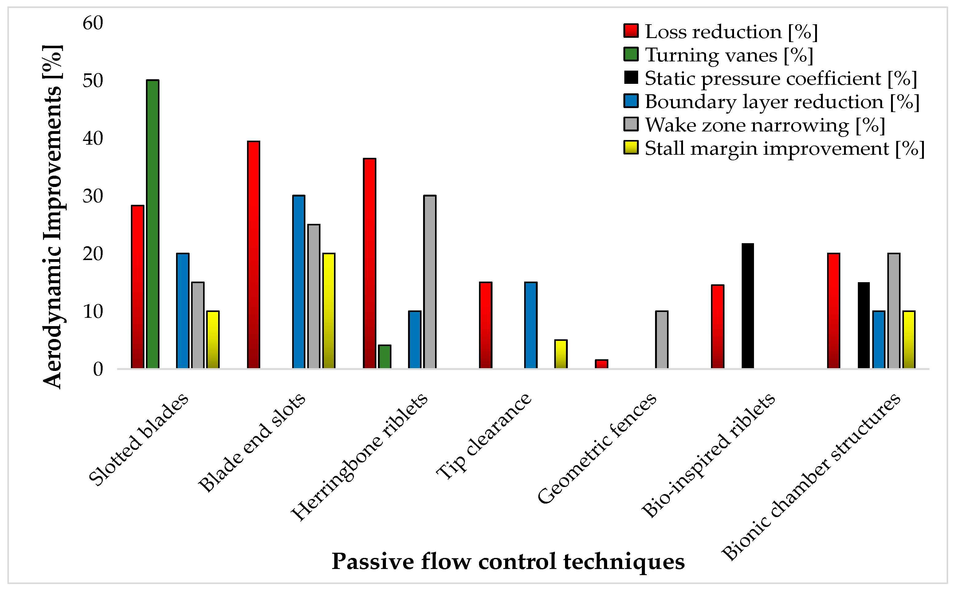
Slotted blades: this technique reduces the loss coefficient by up to 28.3% and prevents boundary layer detachment, significantly improving cascade performance. The placement of slots, particularly between the minimum pressure and separation points, is critical to the method’s effectiveness, especially at high incidence angles. Further research is needed to optimize slot design and placement in three-dimensional cascades.
Vortex generators (VGs): VGs reduce total pressure losses by up to 9% and extend stall margin by suppressing secondary flows like corner separation and endwall cross-flow. Their performance is influenced by factors such as design, placement, and configuration. Non-conventional VG designs, such as doublet and wishbone configurations, show even greater skin friction reduction, further enhancing flow efficiency.
Boundary layer management: When combined with positively bowed blades, this method reduces cascade losses by up to 31.4%. It helps mitigate trailing-edge and corner separation, enhancing the stall margin and providing versatility across a wide range of operational conditions. Other techniques, such as blade end slots, fences, and bionic slanting riblets, also contribute to reduced secondary flow losses, improved flow mixing, and delayed separation.
Stall margin improvement: Vortex generators and slot configurations have shown the most significant improvements in stall margin. VGs, in particular, reduce flow losses and extend the stall margin, making them suitable for various compressor designs. Blade end slots and boundary layer suction have also been effective in mitigating corner separation, improving performance in high-load or high-incidence conditions.
In addition to traditional passive control techniques, bio-inspired designs are showing great promise in enhancing flow stability and compressor efficiency, see Table 2.
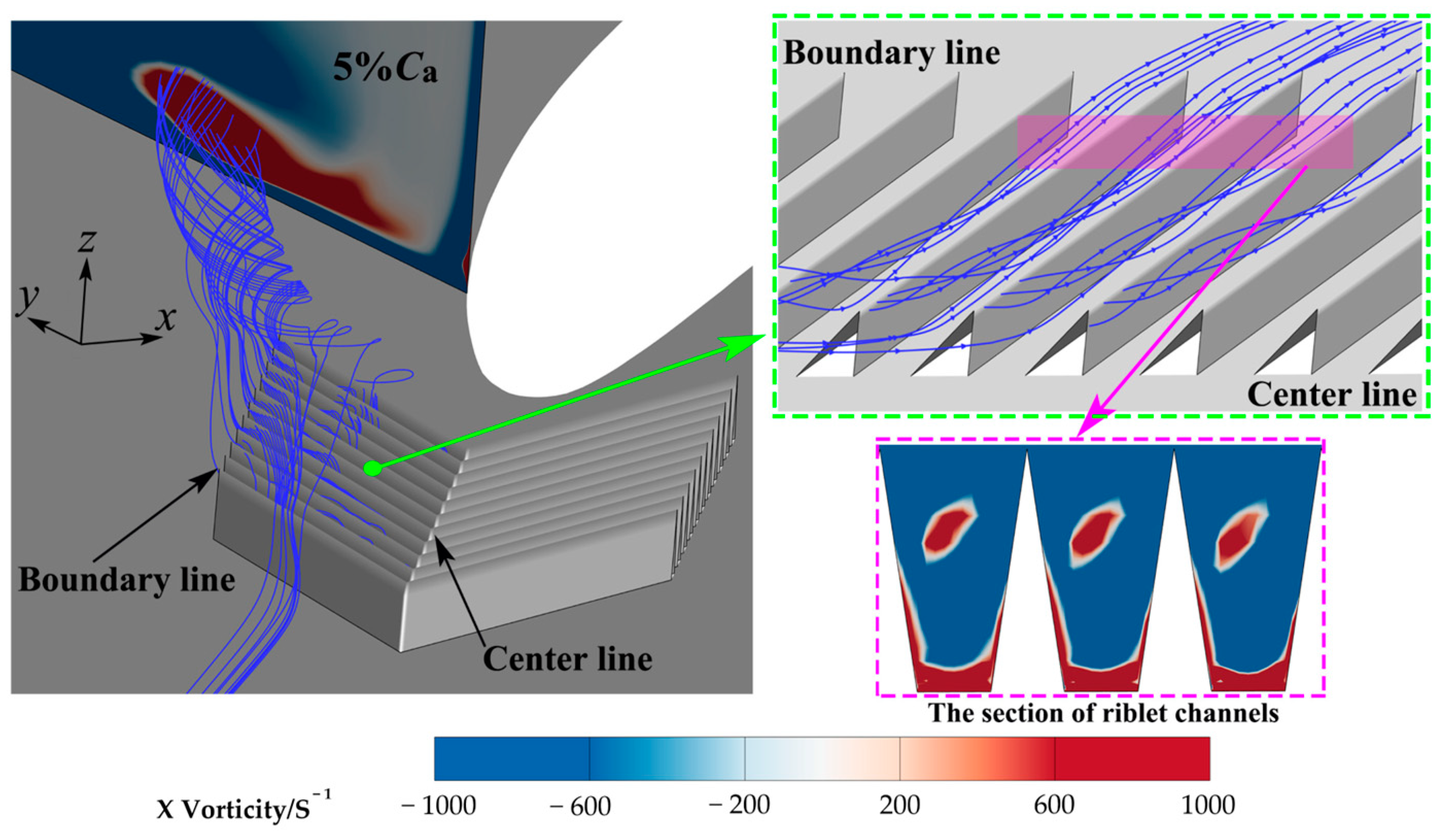
Bio-inspired riblet techniques: Riblets inspired by bird feathers, such as slanting riblets, reduce drag and achieve a 16.8% reduction in pressure loss. Herringbone riblets improve performance further with a 36.4% reduction in pressure loss and enhanced flow turning. Sharkskin-inspired riblets can reduce pressure losses by up to 20.5% in turbulent flow, optimizing cascade performance by controlling flow separation.
Bionic flow control structures: Inspired by dragonfly wings, bionic chambers enhance flow dynamics by increasing turbulent kinetic energy and adjusting the cascade’s incidence angle. This results in a 9.43% reduction in pressure loss and an 8.35% increase in static pressure. Similarly, bionic blade ribs, inspired by peregrine falcons, improve flow mixing and reduce vortex intensity, contributing to a 9.87% reduction in corner losses.
AI and simulation-based techniques: AI-driven Physics-Informed Neural Networks (PINNs) improve flow simulations, addressing complex design problems in compressors. The Bowed LESB Cascade employs leading-edge strake blades to reduce pressure loss by 59.7% while maintaining static pressure rise. AI-based optimizations and computational tools lead to more precise designs, enhancing compressor performance.
Table 3 provides a comparison of various passive flow control methods used in linear cascades for compressors. Each method is evaluated based on its advantages and disadvantages, highlighting aspects such as effectiveness in flow manipulation, impact on performance, ease of implementation, and potential limitations like added complexity or efficiency reduction. The aim is to give a clear overview of each method’s applicability and trade-offs for improving compressor performance.
By combining bio-inspired designs, advanced flow control structures and AI-driven simulations, these approaches play a crucial role in minimizing pressure losses, enhancing flow transitions and optimizing overall compressor performance. This synergy of natural design principles, cutting-edge computational tools and innovative engineering techniques leads to more efficient and high-performing turbomachinery. Figure 12 illustrates the impact of these passive control methods on aerodynamic performance.
Loss reduction: Riblets and grooves stand out for achieving the highest reductions in total pressure loss (up to 36.4%), primarily by suppressing separation and energizing boundary layers. These techniques are particularly effective in high Reynolds number flows or regions with adverse pressure gradients.
Flow turning angle improvements: Blade slots and slotted wingtips excel at enhancing flow turning angles, achieving increases of up to 50°. These techniques are especially useful for applications that require precise control of flow direction, such as high-load conditions or cascades with tight spacing.
Boundary layer stabilization: Techniques like vortex generators and fences help stabilize the boundary layer by reducing turbulence intensity and corner separation. They effectively suppress secondary flows, improving flow uniformity and stability, which is essential for extending the operational range of compressors.
Impact of geometry and placement: The performance of these techniques depends heavily on geometric factors (e.g., riblet height, VG size, or slot span) and precise placement in high-velocity or separation-prone regions. Proper positioning of slanting riblets and optimized VG configurations can significantly reduce corner separation and pressure loss.
Complementary nature of techniques: Combining methods, such as vortex generators with boundary layer suction or riblets with slots, can address multiple aerodynamic challenges at once. This synergy could result in improved flow uniformity, reduced sensitivity to incidence angle variations, and further performance improvements.
Based on the analyzed data, the scalability and integration of each passive flow control method into various compressor designs were evaluated to determine the most suitable methods based on size and design considerations.
A.
Tip clearance flow control
  • Scalability: Adjustments to blade tips or casing can be scaled for both small and large compressors by controlling the blade-casing gap. Precision control for large compressors may be challenging due to thermal expansion and mechanical tolerances.
  • Integration: Implementation often involves modifications to compressor casings or blade tip geometry. For large compressors, precise tolerances and control mechanisms are necessary to prevent adverse effects like vibration.
B.
Gurney flaps
  • Scalability: Simple aerodynamic devices, Gurney flaps scale easily for both small and large compressors. Their straightforward design makes them suitable for large compressors, where complex modifications may be costly.
  • Integration: Installation on existing compressor blades requires minimal structural changes. Gurney flaps can be incorporated during manufacturing or as aftermarket modifications. Drag impact must be considered, particularly in high-efficiency designs.
C.
Vortex generators
  • Scalability: Small aerodynamic devices attached to blade surfaces or end-walls, vortex generators scale easily for smaller compressors without major modifications. For larger compressors, customization may be required to accommodate varying flow conditions, such as higher speeds or pressures.
  • Integration: Integration into compressor designs is relatively straightforward due to their small size. Placement and blade geometry influence effectiveness. Ensuring compatibility with cooling systems and vibration dampers is essential.
D.
Riblets
  • Scalability: Typically applied to surfaces, scalability depends on the manufacturing process. For smaller compressors, riblets can be added to blade surfaces with relative ease, especially on smooth blades. For larger compressors, manufacturing costs may increase, particularly for micro-textured riblets or those requiring specialized fabrication methods.
  • Integration: Integration into existing compressor designs requires minimal disruption. Riblets can be applied as coatings or incorporated into blade surfaces during manufacturing. Ensuring uniformity across large compressor blades presents challenges, especially for complex geometries.
E.
Porous walls
  • Scalability: Dependent on compressor size and design, porous walls can be implemented more easily in smaller compressors. For larger compressors, maintaining uniform porosity across extensive areas while controlling manufacturing costs poses challenges.
  • Integration: Implementation may require casing or internal channel modifications. In some cases, a complete redesign of the flow path may be necessary. Effectiveness depends on maintaining appropriate pressure gradients across the porous surface.
F.
Bionic chambers
  • Scalability: Scalability presents challenges due to complex surface structures. Smaller compressors may gain limited benefits, while larger compressors may experience improved flow stabilization. Manufacturing costs can increase significantly for large-scale applications.
  • Integration: Integration into existing designs may require geometric modifications to blades or casings. Large-scale retrofitting can be cost-prohibitive and technologically demanding due to necessary design alterations.
Passive flow control methods offer various advantages in improving compressor performance, but their scalability and integration depend on factors such as cost, manufacturing complexity, and design constraints. While methods like riblets and vortex generators are easily adaptable and retrofittable, others like bionic chambers and porous walls require significant design modifications. Future advancements in materials and manufacturing could enhance the feasibility of more complex methods, making them more practical for large-scale compressor applications.

3.2. Challenges and Limitations

Despite their advantages, implementing passive flow control methods in real-engine applications presents several challenges. One major limitation is their effectiveness across a broad range of operating conditions. Many passive control techniques, such as riblets, vortex generators, and porous walls, are optimized for specific flow regimes but may lose efficiency under off-design conditions, where variations in Reynolds number, Mach number, and turbulence intensity significantly alter flow behaviour.
Another critical challenge is durability and manufacturability. Many passive control structures require precise fabrication, and their long-term resistance to wear, fouling, and thermal stresses in high-temperature, high-pressure environments remains a concern. For example, riblets and herringbone grooves may degrade due to erosion, reducing their effectiveness over time [188], while porous wall materials must withstand operational stresses without clogging or structural failure [189,190].
A promising solution lies in advanced manufacturing techniques, particularly 3D printing, which has emerged as a transformative technology for producing complex and highly optimized flow control structures. This approach allows for the fabrication of intricate geometries and surface modifications that were previously difficult or impossible to achieve using conventional methods. Three-dimensional printing also offers advantages in design flexibility, cost-effectiveness, and rapid prototyping. By incorporating 3D-printed passive flow control elements—such as riblets, grooves, or vortex generators—engineers can enhance aerodynamic performance by reducing drag and improving boundary layer stability.
In addition to manufacturing innovations, adaptive cascade profiles represent a significant step forward in passive flow control. These profiles dynamically adjust to changing operational conditions, such as varying load or rotational speed, optimizing flow characteristics within the compressor. By improving aerodynamic efficiency and suppressing flow separation in transient or variable conditions, adaptive profiles could enhance overall compressor performance. This adaptability may be achieved through smart materials, active actuators, or bio-inspired mechanisms, enabling real-time geometric adjustments in response to flow variations.
Beyond passive methods, hybrid approaches integrating active flow control have shown promising results. Zhang et al. [191] introduced an adaptive Coanda jet control (ACJC) technique designed to improve compressor performance by preventing flow separation and increasing pressure rise under varying conditions. This system leverages predictive models for incidence angle and optimal injection mass flow rate, developed through statistical and machine learning methods. Simulations indicate that ACJC can reduce pressure loss by up to 21.56%. Furthermore, the study explores shape adaptation Via piezo-ceramic actuation and active flow control through fluid injection, aiming to improve efficiency and extend the operating range of multi-stage compressors [192]. However, challenges persist, particularly in wake disturbances and component matching at the aerodynamic design point. The study focuses on the first two stages of a high-pressure compressor, evaluating shape adaptation and active flow control combinations while balancing structural and aerodynamic requirements.
Finally, integrating passive control technologies into existing compressor designs often requires trade-offs between aerodynamic benefits and mechanical feasibility. Implementing features such as Gurney flaps or fences must be carefully balanced with weight constraints, structural integrity, and ease of maintenance, especially in industrial and aerospace applications.

3.3. Future Directions

Looking ahead, several promising opportunities exist for advancing passive control methods in compressor technology. One major challenge is their validation in multi-stage compressors, as most studies focus on single-stage configurations. Future research should explore how passive flow control techniques can be scaled to address the increased complexities of multi-stage systems. Additionally, hybrid approaches that combine passive and active flow control could provide synergies, improving aerodynamic performance in high-load compressors.
Emerging technologies such as artificial intelligence (AI) and machine learning (ML) offer exciting possibilities for optimizing flow control. By integrating AI-driven models with physics-based simulations, researchers can enhance real-time optimization, predictive maintenance, and design decision-making, particularly for multi-stage compressors. Advances in high-performance computing (HPC) and data-driven turbulence modelling, such as ML-enhanced RANS or LES, could further improve the accuracy and efficiency of flow simulations, enabling faster and more reliable design processes.
To enhance robustness across different operating conditions, future research should focus on adaptive and hybrid control approaches. Advanced material technologies, including self-healing coatings and high-temperature-resistant composites, could extend the longevity of passive control elements. Additionally, high-fidelity simulations and experimental studies under realistic engine conditions will be crucial for refining these methods and ensuring their practical applicability.
Experimental validation remains a critical aspect of future research. High-fidelity experiments, combined with uncertainty quantification, are necessary to strengthen confidence in passive control methods and confirm their effectiveness across various compressor configurations, as part of ongoing efforts such as the project ‘Advanced Fundamental Re-search on the Development of High-Energy-Efficiency Microturboprop Engines for Multirole Unmanned Aerial Vehicles’, developed by COMOTI under project number PN23.12.01.01, which explores innovative approaches to improve aerodynamic performance in UAV propulsion systems.
Furthermore, bio-inspired design innovations—leveraging insights from natural systems and advanced biomimetic materials—could lead to novel solutions for stabilizing flow separation and enhancing aerodynamic efficiency.
Finally, the practical implementation of passive control strategies in industrial compressors presents challenges related to manufacturing feasibility, durability, and integration into existing systems. Addressing these factors will be essential to ensure the successful adoption of passive flow control methods in real-world applications. By overcoming these limitations, passive control strategies can play a key role in next-generation compressor designs, optimizing performance while maintaining reliability and durability.

4. Conclusions

Passive flow control techniques have demonstrated significant potential in enhancing aerodynamic performance in compressor cascades. Bio-inspired designs, such as riblets and grooves, are particularly effective in reducing loss coefficients by narrowing the wake zone, which helps decrease drag and stabilize the boundary layer. Blade slots are highly effective at improving flow turning angles, making them ideal for applications where precise flow direction control and minimizing secondary flow effects are critical. Vortex generators (VGs) are particularly valuable for extending the stall margin and mitigating corner separation, improving stability in off-design conditions.
Other techniques, including fences, slotted wingtips, and endwall grooves, have also proven effective in suppressing corner separation, reducing flow losses, and energizing low-energy fluid. Their impact on boundary layer detachment and turbulence intensity underscores the importance of geometric optimization and precise placement to maximize performance gains. Combining these techniques, tailored to specific aerodynamic parameters such as Reynolds number, turning angle, and boundary layer characteristics, offers potential for further efficiency improvements in high-performance compressors.
This review highlights the diverse range of flow control methods currently being applied to compressor cascades, with a focus on strategies aimed at reducing losses, improving efficiency, and enhancing aerodynamic performance. Passive methods like Gurney flaps, non-axisymmetric endwall contours, and vortex generators have proven effective in reducing flow separation and minimizing secondary flow losses, especially in highly loaded cascades.
Computational advancements, particularly high-fidelity simulations (e.g., LES, DDES), have been essential for better understanding complex flow phenomena within compressor cascades, such as turbulence modelling, corner separation, and vortex dynamics. The use of optimization techniques like multi-objective genetic algorithms has further refined the effectiveness of flow control methods, indicating their potential for practical implementation in compressor design.
Despite these advancements, challenges remain in fully optimizing these techniques for varying operational conditions and ensuring their practical application in commercial turbines. Bridging the gap between laboratory results and real-world performance is crucial, particularly in integrating passive and active control methods and exploring multi-dimensional and transient flow behaviours. Future research should also focus on the long-term durability and energy efficiency of these flow control systems to ensure that performance improvements do not come at the cost of operational costs or reliability.
In conclusion, while significant progress has been made in the area of flow control in compressor cascades, continued innovation and cross-disciplinary collaboration will be essential to unlocking the full potential of these methods in advancing compressor efficiency, especially for modern, high-performance turbomachinery.

Author Contributions

O.D. conceived the structure, and wrote the first draft of the manuscript. E.-G.P. conceived the structure, and reviewed and edited the manuscript. V.D. reviewed and edited the manuscript. All authors have read and agreed to the published version of the manuscript.

Funding

This work was carried out through “Nucleu” Program, part of the National Plan for Research, Development and Innovation 2022–2027, supported by the Romanian Ministry of Research, Innovation and Digitalization, Grant No. PN23.12.01.01.

Institutional Review Board Statement

Not applicable.

Informed Consent Statement

Not applicable.

Data Availability Statement

The original contributions presented in this study are included in the article material. Further inquiries can be directed to the corresponding author(s).

Acknowledgments

The authors acknowledge the use of ChatGPT 3.5 (https://chat.openai.com, accessed on 27 February 2025) for language improvement purposes only.

Conflicts of Interest

The authors declare no conflicts of interest. The funders had no role in the design of the study; in the collection, analyses, or interpretation of data; in the writing of the manuscript; or in the decision to publish the results.

Abbreviations

The following abbreviations are used in this manuscript:
ACJCAdaptive Coanda jet control
AJVGAir–jet vortex generators
AI Artificial Intelligence
CDAControlled diffusion airfoils
CFDComputational fluid dynamics
DDESDelayed Detached Eddy Simulation
EARSMExplicit Algebraic Stress Models
HPCHigh Performance Computing
LESLarge Eddy Simulation
LESBLeading-edge strake blades
LSBLaminar separation bubble
MCAMultiple Circular Arc
MLMachine learning
MVGMicro-Vortex Generators
NSGA IINon-Dominated Sorting Genetic Algorithm
PAFVPartial Average Fluctuation Velocity
PEWRndwall Profiling
PINNPhysics-Informed Neural Networks
RANS Reynolds-Averaged Navier–Stokes
RSMReynolds Stress Models
SBLIShock Wave–Boundary Layer Interactions
SCADouble Circular Arc
SCBShock Control Bump
SSTShear Stress Transport
TLVTip Leakage vortex
URANSUnsteady Reynolds-Averaged Navier–Stokes
VGVortex Generators

References

  1. Zambonini, G.; Ottavy, X.; Kriegseis, J. Corner Separation Dynamics in a Linear Compressor Cascade. J. Fluids Eng. 2017, 139, 061101. [Google Scholar] [CrossRef]
  2. Giorgi, M.G.D.; Luca, C.G.D.; Ficarella, A. Comparison between Synthetic Jets and Continuous Jets for Active Flow Control: Application on a NACA 0015 and a Compressor Stator Cascade. Aerosp. Sci. Technol. 2015, 43, 256–280. [Google Scholar] [CrossRef]
  3. Evans, S.; Coull, J.; Haneef, I.; Hodson, H. Minimizing the loss produced by a turbulent separation using vortex generator jets. AIAA J. 2012, 50, 778–787. [Google Scholar] [CrossRef]
  4. Feng, Y.; Song, Y.; Chen, F.; Liu, H. Effect of endwall vortex generator jets on flow separation control in a linear compressor cascade. Proc. Inst. Mech. Eng. Part G J. Aerosp. Eng. 2015, 229, 2221–2230. [Google Scholar] [CrossRef]
  5. Marks, C.R.; Sondergaard, R.; Wolff, M.; Anthony, R. Experimental comparison of DBD plasma actuators for low Reynolds number separation control. J. Turbomach. 2013, 13, 011024. [Google Scholar] [CrossRef]
  6. Akcayoz, E.; Duc Vo, H.; Mahallati, A. Controlling corner stall separation with plasma actuators in a compressor cascade. J. Turbomach. 2016, 138, 081008. [Google Scholar] [CrossRef]
  7. Staats, M.; Nitsche, W. Active Control of the Corner Separation on a Highly Loaded Compressor Cascade with Periodic Nonsteady Boundary Conditions by Means of Fluidic Actuators. ASME J. Turbomach. 2016, 138, 031004. [Google Scholar] [CrossRef]
  8. Cerretelli, C.; Gharaibah, E. An Experimental and Numerical Investigation on Fluidic Oscillators for Flow Control. In Proceedings of the 37th AIAA Fluid Dynamics Conference and Exhibit, Miami, FL, USA, 25–28 June 2007; AIAA Paper No. 2007-3854. p. 3854. [Google Scholar]
  9. Song, Y.P.; Chen, F.; Yang, J.; Wang, Z.Q. A numerical investigation of boundary layer suction in compound lean compressor cascades. J. Turbomach. 2006, 128, 357–366. [Google Scholar] [CrossRef]
  10. Zhang, Y.; Yu, J.; Chen, F.; Song, Y. Investigation of transition flow on suction surface of highly loaded compressor cascade controlled by plasma actuator. Int. J. Heat Fluid Flow 2024, 105, 109273. [Google Scholar] [CrossRef]
  11. Liang, R.; Lu, H.; Tian, Z.; Wang, H.; Guo, S. Numerical Study on the Effects of Boundary Layer Suction on Flow in the Sectorial Transonic Cascade Under Imitated Near-Stall Condition. Appl. Sci. 2025, 15, 76. [Google Scholar] [CrossRef]
  12. Hergt, A.; Meyer, R.; Engel, K. The capability of influencing secondary flow in compressor cascade by means of passive and active methods. In Proceedings of the First CEAS European Air and Space Conference Century Perspectives, 1st CEAS European Air and Space Conference, Berlin, Germany, 10–13 September 2007; pp. 1–10. [Google Scholar]
  13. Ashill, P.R.; Fulker, J.L.; Hackett, K.C. A review of recent developments in flow control. Aeronaut. J. 2005, 109, 205–232. [Google Scholar] [CrossRef]
  14. Wang, Z.Q.; Su, J.X.; Zhong, J.J. The effect of the pressure distribution in a three-dimensional flow field of a cascade on the type of curved blade. In Proceedings of the ASME 1994 International Gas Turbine and Aeroengine Congress and Exposition, The Hague, The Netherlands, 13–16 June 1994. Paper No. 94-GT-409. [Google Scholar]
  15. Gallimore, S.J.; Bolger, J.J.; Cumpsty, N.A.; Taylor, M.J.; Wright, P.I.; Place, J.M. The use of sweep and dihedral in multistage axial flow compressor blading d Part I: University research and methods development. ASME J. Turbomach. 2002, 124, 533–541. [Google Scholar]
  16. Zhang, L.X.; Wang, S.T. A combination application of tandem blade and endwall boundary layer suction in a highly loaded aspirated compressor outlet vane. Proc. Inst. Mech. Eng. Part A J. Power Energy 2018, 232, 129–143. [Google Scholar]
  17. Hage, W.; Meyer, R.; Paschereit, C. Control of secondary flow in a high loaded compressor stage by means of a groove structure on the sidewalls. In Proceedings of the 25th AIAA Applied Aerodynamics Conference, Miami, FL, USA, 25–28 June 2007. Paper No. 2007-4278. [Google Scholar]
  18. Dinh, C.T.; Heo, M.W.; Kim, K.Y. Aerodynamic performance of transonic axial compressor with a casing groove combined with blade tip injection and ejection. Aero. Sci. Technol. 2015, 46, 176–187. [Google Scholar]
  19. Liu, H.; Li, D.; Chen, H.; Zhang, D. Effects of vortex generator jet on corner separation/stall in high-turning compressor cascade. Trans. Tianjin Univ. 2016, 22, 555–562. [Google Scholar] [CrossRef]
  20. Roland, A. Model Research: The National Advisory Committee for Aeronautics, 1915–1958; NASA History Series SP-4103; NASA: Washington, DC, USA, 1985; Volume 1–2. [Google Scholar]
  21. Spencer, A.M. A Wartime Necessity: The National Advisory Committee for Aeronautics (NACA) and Other National Aeronautical Research Organizations’ Efforts at Innovation During World War II. NASA. Retrieved from NASA. Available online: https://www.nasa.gov/history/a-wartime-necessity/) (accessed on 7 January 2025).
  22. Daum, F.L. Preliminary Experimental Investigation of Airfoils in Cascade (NACA-WR-L-231), 1942, National Advisory Committee for Aeronautics. Retrieved from NASA Technical Reports Server. Available online: https://ntrs.nasa.gov/citations/19930092794 (accessed on 7 January 2025).
  23. Herrig, J.L.; Emery, J.C.; Erwin, J.R. Systematic Two-Dimensional Cascade Tests of NACA 65-Series Compressor Blades at Low Speeds (NACA-RM-L51G31), 1951, National Advisory Committee for Aeronautics. Retrieved from NASA Technical Reports Server. Available online: https://ntrs.nasa.gov/archive/nasa/casi.ntrs.nasa.gov/19930092353.pdf (accessed on 7 January 2025).
  24. Felix, A.R.; Emery, J.C. A Comparison of Typical National Gas Turbine Establishment and NACA Axial-Flow Compressor Blade Section; NACA Research Momerandum, NACA RM 53B26a; NASA: Washington, DC, USA, 1953. [Google Scholar]
  25. Hawthorne, W.R. Rotational flow through cascades Part I. The components of vorticity. Q. J. Mech. Appl. Math. 1955, 8, 266–279. [Google Scholar] [CrossRef]
  26. Lieblein, S. Aerodynamic Design of Axial-Flow Compressors VI—Experimental Flow in Two-Dimensional Cascades; NACA RM E55K0la; Lewis Flight Propulsion Laboratory: Cleveland, OH, USA, 1955. [Google Scholar]
  27. Lindley, C.A. Secondary Flow in Compressor Cascades. Ph.D. Thesis, California Institute of Technology, Pasadena, CA, USA, 1956. [Google Scholar]
  28. Kriebel, A.R. Stall Propagation in a Cascade of Airfoils; Report Number 36; Gas Turbine Laboratory, Massachusetts Institute of Technology: Cambridge, MA, USA, 1956. [Google Scholar]
  29. Schlichting, H. Cascade Flow Problems. In Tenth Meeting of the Wind Tunnel and Model Testing Panel, 18–21 February; Report 93; Paris Advisory Group for Aeronautical Research and Development: Paris, France, 1957. [Google Scholar]
  30. Lieblein, S. Analysis of Experimental Low-Speed Loss and Stall Characteristics of Two-Dimensional Compressor Blade Cascades; NACA RM E57A28; National Advisory Committee for Aeronautics, Lewis Flight Propulsion Laboratory: Cleveland, OH, USA, 1957. [Google Scholar]
  31. Lieblein, S.; Roudebush, W.H. Theoretical Loss Relations for Low-Speed Two-Dimensional-Cascade Flow. Technical Note 3662; National Advisory Committee for Aeronautics, Lewis Flight Propulsion Laboratory: Cleveland, OH, USA, 1956. [Google Scholar]
  32. Swan, W.C. A Practical Method of Predicting Transonic Compressor Performance. ASME J. Eng. Power 1961, 83, 322–330. [Google Scholar]
  33. Lieblein, S. Loss and Stall Analysis of Compressor Cascades. ASME J. Basic Eng. 1959, 81, 387–400. [Google Scholar] [CrossRef]
  34. Railly, J.W.; Howard, J.H.G. Velocity Profile Development in Axial-Flow Compressors. J. Mech. Eng. Sci. 1962, 4, 166–176. [Google Scholar] [CrossRef]
  35. Lakshminarayana, B.; Horlock, J.H. Review: Secondary flows and losses in cascades and axial-flow turbomachinery. Int. J. Mech.Sci. 1963, 5, 287–307. [Google Scholar] [CrossRef]
  36. Shaalan, M.R.A. A Wind-Tunnel Investigation of the Stalling Performance of Two Compressor Cascades of Different Aspect Ratios at Low Speed; Ministry of Technology, Aeronautical Research Council: Liverpool, UK, 1970. [Google Scholar]
  37. Marsh, H. Wall Boundary Layers in Cascades, Procurement Executive; Ministry of Defence, Aeronautical Research Council: Bedford, UK, 1978. [Google Scholar]
  38. Glynn, D.R. Calculation of secondary flow in cascades including effects of Bernoulli surface distortion. Int. J. Heat Fluid Flow 1982, 3, 73–80. [Google Scholar] [CrossRef]
  39. Cyrus, V. Experimental investigation of losses and secondary flow in an axial compressor stage. Forsch. Im Ingenieurwesen 1985, 51, 2. [Google Scholar] [CrossRef]
  40. Dring, R.P.; Joslyn, H.D.; Hardin, L.W. An investigation of axial compressor rotor aerodynamics. J. Eng. Gas Turbines Power 1982, 104, 84–96. [Google Scholar] [CrossRef]
  41. Joslyn, H.D.; Dring, R.P. Axial compressor stator aerodynamics. J. Eng. Gas Turbines Power 1985, 107, 485–492. [Google Scholar] [CrossRef]
  42. Schulz, H.D.; Gallus, H.E.; Lakshminarayana, B. Three-dimensional separated flow field in the endwall region of an annular compressor cascade in the presence of rotor-stator interaction: Part 1—Quasi-steady flow field and comparison with steady-state data. J. Turbomach. 1990, 112, 669–678. [Google Scholar] [CrossRef]
  43. Li, Y.; Ye, D.; Lu, B. Experimental investigation of the three dimensional flow in an annular compressor cascade at large incidence. J. Therm. Sci. 1992, 1, 3–10. [Google Scholar] [CrossRef]
  44. Barankiewicz, W.S.; Hathaway, M.D. Impact of variable-geometry stator hub leakage in a low speed axial compressor. In Proceedings of the ASME 1998 International Gas Turbine and Aeroengine Congress and Exhibition, Stockholm, Sweden, 2–5 June 1998; ASME: New York, NY, USA, 1998; pp. 1–9. [Google Scholar]
  45. Spacy, W.L., II. Effect of Cranulations on Three Dimensional Losses in a Linear Compressor Cascade. AFIT/GAE/ENY/93D-26. Master’s Thesis, Air Force Institute of Technology, Dayton, OH, USA, December 1993. [Google Scholar]
  46. Crook, A.J.; Greitzer, E.M.; Tan, C.S.; Adamczyk, J.J. Numerical Simulation of Compressor Endwall and Casing Treatment Flow Phenomena. J. Turbomach. 1993, 115, 501–512. [Google Scholar] [CrossRef]
  47. Kang, S.; Hirsch, C. Experimental Study on the Three-Dimensional Flow Within a Compressor Cascade With Tip Clearance: Part II—The Tip Leakage Vortex. J. Turbomach. 1993, 115, 444–450. [Google Scholar] [CrossRef]
  48. Kang, S.; Hirsch, C. Tip Leakage Flow in Linear Compressor Cascade. J. Turbomach. 1994, 116, 657. [Google Scholar] [CrossRef]
  49. Hobson, G.V.; Williams, A.J.H.; Ganaim Rickel, H.J. Laser-Doppler-Velocimetry Measurements in a Cascade of Compressor Blades at Stall. J. Turbomach. 1998, 120, 170–178. [Google Scholar] [CrossRef]
  50. Sasaki, T.; Breugelmans, F. Comparison of Sweep and Dihedral Effects on Compressor Cascade Performance. J. Turbomach. 1998, 120, 454–463. [Google Scholar] [CrossRef]
  51. Lepicovsky, J.; Chima, R.V.; Jett, T.A.; Bencic, T.J.; Weiland, K.E. Investigation of Flow Separation in a Transonic-Fan Linear Cascade Using Visualization Methods; NASA/TM-2000-210S21; NASA Center for Aerospace Information: Washington, DC, USA, 2000. [Google Scholar]
  52. Tateishi, A.; Watanabe, T.; Himeno, T.; Uzawa, S. Numerical method for an assessment of steady and motion-excited flowfields in a transonic cascade wind tunnel. J. Glob. Power Propuls. Soc. 2017, 1, 171–183. [Google Scholar] [CrossRef]
  53. Hergt, A.; Danninger, T.; Klinner, J.; Grund, S.; Beversdorff, M.; Werner-Spatz, C. Effect of Leading-Edge Erosion on the Performance of Transonic Compressor Blades. Int. J. Turbomach. Propuls. Power 2024, 9, 1. [Google Scholar] [CrossRef]
  54. Wang, T. 15—The gas and steam turbines and combined cycle in IGCC systems. In Integrated Gasification Combined Cycle (IGCC) Technologies; Wang, T., Stiegel, G., Eds.; Woodhead Publishing: Saskatoon, UK, 2017; pp. 497–640. ISBN 9780081001677. [Google Scholar] [CrossRef]
  55. Kamranpey, A. A study on effects of mass flow rate and compressor pressure ratio on gas turbine cycle performance. Int. J. IC Engines Gas Turbines 2022, 8, 1–8. [Google Scholar]
  56. Allen, C.W.; Balaji, P.; de Oliveira, M. Axial Compressor Fouling and its Effect on Gas Turbine Fuel Consumption and Emissions. In Proceedings of the ASME Turbo Expo 2020: Turbomachinery Technical Conference and Exposition, Virtual, Online, 21–25 September 2020; Volume 5: Controls, Diagnostics, and Instrumentation; Cycle Innovations; Cycle Innovations: Energy Storage; V005T05A030. ASME: New York, NY, USA, 2021. [Google Scholar] [CrossRef]
  57. Al-Shami, M.; Mohamed, O.; Abu Elhaija, W. Energy-Efficient Control of a Gas Turbine Power Generation System. Designs 2023, 7, 85. [Google Scholar] [CrossRef]
  58. Schreiber, H.A. Investigation of Two Transonic Compressor Cascades and Comparison with Rotor Data; Technical Report; Deutsches Zentrum für Luft- und Raumfahrt: Cologne, Germany, 1976. [Google Scholar]
  59. Dunker, R.J.; Strinning, P.E.; Weyer, H.B. Experimental Study of the Flow Field Within a Transonic Axial Compressor Rotor by Laser Velocimetry and Comparison with Through-Flow Calculations; Paper No. 77-GT-28; American Society of Mechanical Engineers: New York, NY, USA, 1977. [Google Scholar]
  60. Schreiber, H.A.; Starken, H. Evaluation of Blade Element Performance of Compressor Rotor Blade Cascades in Transonic and Low Supersonic Flow Range. In Proceedings of the 5th International Symposium on Air Breathing Engines, Bangalore, India, 16–21 February 1981; pp. 61–67. [Google Scholar]
  61. Schreiber, H.A.; Starken, H. Experimental Cascade Analysis of a Transonic Compressor Rotor Blade Section. ASME J. Eng. Gas Turbines Power 1984, 106, 288–294. [Google Scholar] [CrossRef]
  62. Resmini, M. Numerical Investigation of the Solidity Effect on a Linear Compressor Cascade Performance and Stability. Master’s Thesis, Politecnico di Milano Facoltà di Ingegneria Industriale Corso di Laurea Magistrale in Ingegneria Meccanica, Milan, Italy, 2011. [Google Scholar]
  63. Munoz Lopez, E.J.; Hergt, A.; Grund, S.; Gümmer, V. The New Chapter of Transonic Compressor Cascade Design at the DLR. ASME J. Turbomach. 2023, 145, 081001. [Google Scholar] [CrossRef]
  64. Reisinger, L.; Bieli, P.; Gümmer, V. Numerical Analysis of the Boundary Layer Behavior of Low-Speed Linear Cascade Compressor Airfoils With Single and Tandem Configurations. In Proceedings of the ASME Turbo Expo 2024: Turbomachinery Technical Conference and Exposition, London, UK, 24–28 June 2024; Volume 12A: Turbomachinery—Axial Flow Fan and Compressor Aerodynamics; V12AT29A048. ASME: New York, NY, USA, 2024. [Google Scholar] [CrossRef]
  65. Moore, R.D. Rotor Tip Clearance Effects on Overall and Blade-Element Performance of Axial-Flow Transonic Fan Stage. U.S. Patent NASA-TP-2049, 1 September 1982. [Google Scholar]
  66. Inour, M.; Kuroumaru, M. Structure of Tip Clearance Flow in an Isolated Axial Compressor Rotor. ASME J. Turbomach. 1989, 111, 250–256. [Google Scholar]
  67. Williams, R.; Gregory-Smith, D.; He, L.; Ingram, G. Experiments and Computations on Large Tip Clearance Effects in a Linear Cascade. In Proceedings of the ASME Turbo Expo 2008: Power for Land, Sea, and Air, Berlin, Germany, 9–13 June 2008; Volume 6: Turbomachinery, Parts A, B, and C. ASME: New York, NY, USA, 2009; pp. 335–347. [Google Scholar] [CrossRef]
  68. Zaki, T.A.; Wissink, J.G.; Rodi, W.; Durbin, P.A. Direct numerical simulations of transition in a compressor cascade: The influence of free-stream turbulence. J. Fluid Mech. 2010, 665, 57–98. [Google Scholar] [CrossRef]
  69. Fischer, A.; Büttner, L.; Czarske, J.; Gottschall, M.; Mailach, R.; Vogeler, K. Investigation of the tip clearance flow in a compressor cascade using a novel laser measurement technique with high temporal resolution. In Proceedings of the ASME Turbo Expo 2011 GT2011, Vancouver, BC, Canada, 6–10 June 2011. [Google Scholar]
  70. Ma, W.; Ottavy, X.; Lu, L.; Leboeuf, F.; Gao, F. Experimental Study of Corner Stall in a Linear Compressor Cascade. Chin. J. Aeronaut. 2011, 24, 235–242. [Google Scholar] [CrossRef]
  71. Lee, Y.T.; Laurita, M.J.; Feng, J.; Merkle, C.L. Characteristics of Tip-Clearance Flows of a Compressor Cascade and a Propulsion Pump. In Proceedings of the ASME 1997 International Gas Turbine and Aeroengine Congress and Exhibition, Orlando, FL, USA, 2–5 June 1997; Volume 1: Aircraft Engine; Marine; Turbomachinery; Microturbines and Small Turbomachinery; V001T03A003. ASME: New York, NY, USA, 2014. [Google Scholar] [CrossRef]
  72. Kanjirakkad, V. Experimental Study of Endwall Flow in a Low-Speed Linear Compressor Cascade: Effect of Over-Tip Leakage (Version 1); University of Sussex: Falmer, UK, 2017; Available online: https://hdl.handle.net/10779/uos.23446844.v1 (accessed on 7 January 2025).
  73. Toledo-Velázquez, M.; Tolentino-Eslava, G.; Cervera-Morales, M.L.; Abugaber-Francis, J.; Rangel-López, L.R. Experimental Study of the Flow in a Linear Cascade of Axial Compressor Blades. Int. J. Sci. Eng. Appl. Sci. (IJSEAS) 2017, 3, 66–72. [Google Scholar]
  74. Meng, F.; Tang, J.; Li, J.; Zhong, J.; Guo, P. Large eddy simulation of shock wave/boundary layer interactions in a transonic compressor cascade. Phys. Fluids 2024, 36, 076101. [Google Scholar] [CrossRef]
  75. Li, Z.; Du, J.; Ottavy, X.; Zhang, H. Quantification and Analysis of the Irreversible Flow Loss in a Linear Compressor Cascade. Entropy 2018, 20, 486. [Google Scholar] [CrossRef]
  76. Mao, K.; Liu, B.; Tang, T. Control of Tip Leakage Flow in Axial Flow Compressor Cascade by Suction on the Blade Tip. J. Appl. Fluid Mech. 2018, 11, 137–149. [Google Scholar] [CrossRef]
  77. Klinner, J.; Hergt, A.; Grund, S.; Willert, C.E. Experimental investigation of shock-induced separation and flow control in a transonic compressor cascade. Exp. Fluids 2019, 60, 96. [Google Scholar] [CrossRef]
  78. Tian, S.; Gutierrez Salas, M. Numerical Investigation on the Pressure Perturbation of a Transonic Aeroelastic Compressor Rig. In Proceedings of the GPPS Chania 20 Global Power and Propulsion Society, Chania, Greece, 7–9 September 2020. [Google Scholar]
  79. Régis, K.; Marlène, S.; Stéphane, M. Aerodynamic investigation of a linear cascade with tip gap using large-eddy simulation. J. Glob. Power Propuls. Soc. 2021, 5, 39–49. [Google Scholar] [CrossRef]
  80. Klinner, J.; Hergt, A.; Grund, S.; Willert, C.E. High-Speed PIV of shock boundary layer interactions in the transonic buffet flow of a compressor cascade. Exp. Fluids 2021, 62, 58. [Google Scholar] [CrossRef]
  81. Tang, X.; Wu, F.; Yang, X.; Yang, M. Internal Flow Structures in Tip Clearance Based on Time-Resolved Schlieren Visualization and Numerical Simulations. J. Aerosp. Eng. 2025, 38, 04024110. [Google Scholar] [CrossRef]
  82. Byerley, A.R.; Stormer, O.; Baughn, J.W.; Simon, T.W.; Van Treuren, K.W.; List, J. Using Gurney Flaps to Control Laminar Separation on Linear Cascade Blades. In Proceedings of the ASME Turbo Expo 2002: Power for Land, Sea, and Air, Volume 5: Turbo Expo 2002, Parts A and B. Amsterdam, The Netherlands, 3–6 June 2002; pp. 1191–1199. [Google Scholar] [CrossRef]
  83. Myose, R.Y.; Lietsche, J.C.; Scholz, D.; Zinge, H.; Hayashibara, S.; Heron, I. Flow Visualization Study on the Effect of a Gurney Flap in a Low Reynolds Number Compressor Cascade. In Proceedings of the 6th AIAA Aviation Technology, Integration and Operations Conference (ATIO), Wichita, Kansas, 25–27 September 2006; pp. 2006–7809. [Google Scholar]
  84. Jingjun, Z.; Shaobing, H.; Huawei, L.; Xiaoxu, K. Effect of tip geometry and tip clearance on aerodynamic performance of a linear compressor cascade. Chin. J. Aeronaut. 2013, 26, 583–593. [Google Scholar]
  85. Mdouki, R.; Bois, G.; Gahmousse, A. Enhancing aerodynamic performances of highly loaded compressor cascade via Gurney flap. UPB Sci. Bull. Ser. D 2015, 77, 41–52. [Google Scholar]
  86. Nilavarasan, T.; Joshi, G.N.; Chandel, S. Effect of Gurney Flaps on the Aerodynamic Characteristics of NACA 0010 Cascades. Int. J. Turbo Jet-Engines 2019, 39, 343–355. [Google Scholar] [CrossRef]
  87. Liebeck, R.H. Design of subsonic airfoils for high lift. J. Aircr. 1978, 15, 547–561. [Google Scholar]
  88. Hergt, A.; Meyer, R.; Engel, K. Effects of Vortex Generator Application on the Performance of a Compressor Cascade. J. Turbomach. 2013, 135, 021026. [Google Scholar] [CrossRef]
  89. Diaa, A.M.; El-Dosoky, M.F.; Ahmed, M.A.; Abdel-Hafez, O.E. Boundary Layer Control of an Axial Compressor Cascade Using Nonconventional Vortex Generators. In Proceedings of the ASME 2015 International Mechanical Engineering Congress and Exposition, Houston, TX, USA, 13–19 November 2015; Volume 1: Advances in Aerospace Technology; V001T01A044. ASME: New York, NY, USA, 2016. [Google Scholar] [CrossRef]
  90. Hu, J.; Wang, R.; Wu, P.; Li, F. Synthetic Separation Control Using Vortex Generator and Slot Jet in a High Load Compressor Cascade. J. Appl. Fluid Mech. 2017, 10, 1305–1318. [Google Scholar] [CrossRef]
  91. Ma, S.; Chu, W.; Zhang, H.; Li, X.; Kuang, H. Effects of modified micro-vortex generators on aerodynamic performance in a high-load compressor cascade. Proc. Inst. Mech. Eng. Part A J. Power Energy 2019, 233, 309–323. [Google Scholar] [CrossRef]
  92. Kan, X.; Wang, S.; Yang, L.; Zhong, J. Vortex dynamic mechanism of curved blade affecting flow loss in compressor cascade during corner stall process. Aerosp. Sci. Technol. 2019, 85, 443–452. [Google Scholar] [CrossRef]
  93. Ma, S.; Chu, W.; Zhang, H.; Li, X.; Kuang, H. A combined application of micro-vortex generator and boundary layer suction in a high-load compressor cascade. Chin. J. Aeronaut. 2019, 32, 1171–1183. [Google Scholar] [CrossRef]
  94. Xu, W.; Zou, S.; Tang, C.; Ren, G.; Sun, D. Effect of the leading-edge vortex generator on the performance of the linear cascade. Phys. Fluids 2024, 36, 056121. [Google Scholar] [CrossRef]
  95. Ren, X.; Meng, T.; Zhu, H.; Ji, L. Vortex generator evaluation models and flow mechanisms for compressor cascade. Phys. Fluids 2024, 36, 115156. [Google Scholar] [CrossRef]
  96. Kan, X.-X.; Lu, H.-W.; Zhong, J.-J. Topological characterization of vortex structures on a transonic compressor stator during the stalling process. Proc. Inst. Mech. Eng. Part G J. Aerosp. Eng. 2016, 230, 566–580. [Google Scholar]
  97. Muller, R.; Vogeler, K.; Sauer, H.; Hoeger, M. Endwall Boundary Layer Control in Compressor Cascades. In Proceedings of the ASME Turbo Expo 2004: Power for Land, Sea, and Air, Vienna, Austria, 14–17 June 2004; Volume 5: Turbo Expo 2004, Parts A and B. ASME: New York, NY, USA, 2008; pp. 427–435. [Google Scholar] [CrossRef]
  98. Harvey, N.; Offord, T. Some Effects of Non-Axisymmetric End Wall Profiling on Axial Flow Compressor Aerodynamics: Part II—Multi-Stage HPC CFD Study; ASME: New York, NY, USA, 2008. [Google Scholar] [CrossRef]
  99. Reising, S.; Schiffer, H. Non-Axisymmetric End Wall Profiling in Transonic Compressors—Part I: Improving the Static Pressure Recovery at Off-Design Conditions by Sequential Hub and Shroud End Wall Profiling. In Proceedings of the ASME Turbo Expo 2009: Power for Land, Sea, and Air, Orlando, FL, USA, 8–12 June 2009; Volume 7: Turbomachinery, Parts A and B. ASME: New York, NY, USA, 2010; pp. 11–24. [Google Scholar] [CrossRef]
  100. Hergt, A.; Meyer, R.; Liesner, K.; Nicke, E. A new approach for compressor endwall contouring. In Proceedings of the ASME Turbo Expo 2011 GT2011, Vancouver, BC, Canada, 6–10 June 2011. GT2011-458. [Google Scholar]
  101. Gao, F.; Ma, W.; Zambonini, G.; Boudet, J.; Ottavy, X.; Lu, L.; Shao, L. Large-eddy simulation of 3-D corner separation in a linear compressor cascade. Phys. Fluids 2015, 27, 85–105. [Google Scholar] [CrossRef]
  102. Reutter, O.; Rozanski, M.; Hergt, A.; Nicke, E. Advanced endwall contouring for loss reduction and outflow homogenization for an optimized compressor cascade. In Proceedings of the 11th European Conference on Turbomachinery Fluid dynamics & Thermodynamics ETC11, Madrid, Spain, 23–27 March 2015. [Google Scholar]
  103. Gao, F.; Zambonini, G.; Boudet, J.; Ottavy, X.; Lu, L.; Shao, L. Unsteady behavior of corner separation in a compressor cascade: Large eddy simulation and experimental study. Proc. Inst. Mech. Eng. Part A J. Power Energy 2015, 229, 508–519. [Google Scholar] [CrossRef]
  104. Poulain, A. RANS & WMLES Simulations of Compressor Corner Separation. Degree Project in Vehicle Engineering, Second Cycle, KTH Royal Institute of Technology, School of Engineering Sciences, Stockholm, Sweden, 2020. [Google Scholar]
  105. Djedai, H.; Mdouki, R.; Mansouri, Z.; Aouissi, M. Numerical investigation of three-dimensional separation control in an axial compressor cascade. Int. J. Heat Technol. 2017, 35, 657–662. [Google Scholar] [CrossRef]
  106. Voß, C.; Aulich, M.; Kaplan, B.; Nicke, E. Automated Multi-objective Optimization in Axial Compressor Blade Design; ASME Paper GT2006-90420; ASME: New York, NY, USA, 2008. [Google Scholar]
  107. Available online: https://www.trace-portal.de/userguide/trace/index.html (accessed on 10 December 2024).
  108. Sun, J.; Ottavy, X.; Liu, Y.; Lu, L. Corner separation control by optimizing blade end slots in a linear compressor cascade. Aerosp. Sci. Technol. 2017, 114, 106737. [Google Scholar]
  109. Wei, M. Experimental Investigation of Corner Stall in a Linear Compressor Cascade. Ph.D. Thesis, École Centrale De Lyon, Lyon, France, 2012. Numéro d’ordre: 2012-02. [Google Scholar]
  110. Lei, V.M. A Simple Criterion for Three-Dimensional Flow Separation in Axial Compressors. Ph.D. Thesis, Massachusetts Institute of Technology, Cambridge, MA, USA, 2006. [Google Scholar]
  111. Liu, B.; Yu, X.; Liu, H.; Jiang, H.; Yuan, H.; Xu, Y. Application of SPIV in turbomachinery. Exp. Fluids 2006, 40, 621–642. [Google Scholar]
  112. Liu, H.; Yu, Y.; Chen, H.; Yu, M.; Zhang, D. A parametric investigation of endwall vortex generator jet on the secondary flow control for a high turning compressor cascade. J. Therm. Sci. Technol. 2017, 12, JTST0006. [Google Scholar] [CrossRef]
  113. Jiaguo, H.; Rugen, W.; Renkang, L.; Chen, H.; Qiushi, L. Experimental investigation on separation control by slot jet in highly loaded compressorcascade. Proc. Inst. Mech. Eng. Part G J. Aerosp. Eng. 2017, 232, 1704–1714. [Google Scholar] [CrossRef]
  114. Cong, C.; Huaping, L.; Fu, C. Effect of the end-wall vortex generator jets on the performance of a high subsonic compressor cascade. Proc. Inst. Mech. Eng. Part A J. Power Energy 2018, 233, 095765091878950. [Google Scholar] [CrossRef]
  115. Hu, J.; Wang, R.; Huang, D. Flow control mechanisms of a combined approach using blade slot and vortex generator in compressor cascade. Aeros Sci. Technol. 2018, 78, 320–331. [Google Scholar] [CrossRef]
  116. EL-Sheikh, M.; El-Batsh, H.; Ali, M.A.A.; Zanoun, E.S. Passive Flow Separation Control in Linear Compressor Cascade. In Proceedings of the Novel Intelligent and Leading Emerging Sciences Conference (NILES), Giza, Egypt, 28–30 October 2019; pp. 106–111. [Google Scholar] [CrossRef]
  117. Nia, B.B.; Gharehghani, A.; Zadeh, S.S.S.; Egan, V. Effect of optimal slot location on the performance of cascades of blades. Proc. Inst. Mech. Eng. Part G J. Aerosp. Eng. 2021, 235, 2208–2224. [Google Scholar]
  118. Chen, Y.; Yang, L.; Zhong, J. Numerical study on endwall fence with varying geometrical parameters in a highly-loaded compressor cascade. Aerosp. Sci. Technol. 2019, 94, 105390. [Google Scholar]
  119. Liu, Y.; Sun, J.; Tang, Y.; Lu, L. Effect of Slot at Blade Root on Compressor Cascade Performance under Different Aerodynamic Parameters. Appl. Sci. 2016, 6, 421. [Google Scholar] [CrossRef]
  120. Botao, Z.; Bo, L.; Hejian, W.; Xiaochen, M. Effect of endwall suction on aerodynamic performance of compressor cascade with tip clearance at a large incidence angle. Proc. Inst. Mech. Eng. Part A J. Power Energy 2021, 235, 095765092098395. [Google Scholar] [CrossRef]
  121. Wang, B.; Wu, Y.; Spence, S. Loss reduction in a high-speed compressor cascade using an L-shaped endwall groove to generate a streamwise vortex. Aerosp. Sci. Technol. 2022, 123, 107486. [Google Scholar] [CrossRef]
  122. Wang, H.; Liu, B.; Mao, X.; Zhang, B.; Yang, Z. Combined Flow Control Strategy Investigation for Corner Separation and Mid-Span Boundary Layer Separation in a High-Turning Compressor Cascade. Entropy 2022, 24, 570. [Google Scholar] [CrossRef]
  123. Xin, J.; Liu, X.; Zhao, L.; Wu, H.; Zhitao, T.; Lu, H. Impact of Slots on the Aerodynamic Performance of the Variable Inlet Guide Vane Cascade of a Centrifugal Compressor. J. Appl. Fluid Mech. 2023, 16, 245–256. [Google Scholar] [CrossRef]
  124. El-Sheikh, M.; El-Batsh, H.; Zanoun, E.S.; Attia, A. Numerical and experimental investigations of flow separation control through a linear compressor cascade. Discov. Appl. Sci. 2024, 6, 450. [Google Scholar] [CrossRef]
  125. Qiang, X.; Li, J.; Ma, Y. Experimental test of a compressor cascade with non-axisymmetric end-wall contouring at off-design conditions. Appl. Therm. Eng. 2024, 240, 122208. [Google Scholar]
  126. Ramzi, M.; Bois, G.; Abderrahmane, G. Numerical Study of Passive Control with Slotted Blading in Highly Loaded Compressor Cascade at Low Mach Number. Int. J. Fluid Mach. Syst. 2011, 4, 97–103. [Google Scholar] [CrossRef]
  127. Panchala, S.; Mayavansh, V. Experimental study of flow through compressor Cascade. Therm. Eng. 2017, 10, 234–243. [Google Scholar] [CrossRef]
  128. Cao, Z.; Liu, B.; Zhang, T.; Yang, X.; Chen, P. Influence of coupled boundary layer suction and bowed blade on flow field and performance of a diffusion cascade. Chin. J. Aeronaut. 2017, 30, 249–263. [Google Scholar] [CrossRef]
  129. Tang, Y.; Liu, Y.; Lu, L.; Lu, H.; Wang, M. Experimental Investigation of Flow Control Using Blade End Slots in a Highly Loaded Compressor Cascade. In Proceedings of the 17th International Symposium on Transport Phenomena and Dynamics of Rotating Machinery, Maui, HI, USA, 16–21 December 2017. [Google Scholar]
  130. Tang, Y.; Liu, Y.; Lu, L. Evaluation of Compressor Blading With Blade End Slots and Full-Span Slots in a Highly Loaded Compressor Cascade. J. Turbomach. 2019, 141, 121002. [Google Scholar]
  131. Sun, P.; Yu, J.Y.; Xu, W.F. Effect of a Tip Groove on the Performance of Compressor Linear Cascade. Fluid Dyn. 2023, 58, 670–683. [Google Scholar] [CrossRef]
  132. Sun, J.; Liu, Y.; Lu, L.; Wang, Q. Control of Corner Separation to Enhance Stability in a Linear Compressor Cascade by Boundary Layer Suction. Procedia Eng. 2014, 80, 380–391. [Google Scholar]
  133. Bell, R.M.; Fottner, L. Investigations of Shock/Boundary-Layer Interaction in a Highly Loaded Compressor Cascade. In Proceedings of the ASME 1995 International Gas Turbine and Aeroengine Congress and Exposition, Houston, TX, USA, 5–8 June 1995; Volume 1: Turbomachinery; V001T01A016. ASME: New York, NY, USA, 2015. [Google Scholar] [CrossRef]
  134. Flaszynski, P.; Doerffer, P.; Szwaba, R.; Kaczynski, P.; Piotrowicz, M. Shock Wave Boundary Layer Interaction on Suction Side of Compressor Profile in Single Passage Test Section. J. Therm. Sci. 2015, 24, 510–515. [Google Scholar] [CrossRef]
  135. Liu, Y.; Sun, J.; Lu, L. Corner Separation Control by Boundary Layer Suction Applied to a Highly Loaded Axial Compressor Cascade. Energies 2014, 7, 7994–8007. [Google Scholar] [CrossRef]
  136. Engelmann, D.; Sinkwitz, M.; di Mare, F.; Koppe, B.; Mailach, R.; Ventosa-Molina, J.; Fröhlich, J.; Schubert, T.; Niehuis, R. Near-Wall Flow in Turbomachinery Cascades. Int. J. Turbomach. Propuls. Power 2021, 6, 9. [Google Scholar] [CrossRef]
  137. Liu, Y.; Zhao, W.; Zhao, Q.; Zhou, Q.; Xu, J. Passage shock wave/boundary layer interaction control for transonic compressors using bumps. Chin. J. Aeronaut. 2022, 35, 82–97. [Google Scholar] [CrossRef]
  138. Gall, M.; Dumitrescu, O.; Drăgan, V.; Crunțeanu, D.E. Effects of Perforated Plates on Shock Structure Alteration for NACA0012 Airfoils. Inventions 2024, 9, 28. [Google Scholar] [CrossRef]
  139. Drăgan, V.; Dumitrescu, O.; Gall, M.; Prisăcariu, E.G.; Gherman, B. Experimental Identification of a New Secondary Wave Pattern in Transonic Cascades with Porous Walls. Aerospace 2024, 11, 946. [Google Scholar] [CrossRef]
  140. Li, B.; Zhou, X.; Luo, L.; Du, W. Effects of Number of Bleed Holes on Shock-Wave/Boundary-Layer Interactions in a Transonic Compressor Stator. J. Therm. Sci. 2024, 33, 611–624. [Google Scholar] [CrossRef]
  141. Li, B.; Zhou, X.; Luo, L.; Du, W. Effects of bleed pressure on shock-wave/boundary-layer interactions in a transonic compressor stator with suction holes. Int. J. Turbo Jet-Engines 2024, 41, 929–945. [Google Scholar] [CrossRef]
  142. Sheng, X.; Wang, M.; Yang, C.; Han, G.; Lu, X. Control of shock–boundary layer interaction in a transonic compressor cascade via heat transfer at a low Reynolds number. Appl. Therm. Eng. 2024, 239, 122183. [Google Scholar] [CrossRef]
  143. Meng, F.; Li, K.; Guo, P.; Gan, J.; Li, J. Experimental and Numerical Investigations of Shock-Wave Boundary Layer Interactions in a Highly Loaded Transonic Compressor Cascade. J. Therm. Sci. 2024, 33, 158–171. [Google Scholar] [CrossRef]
  144. Liu, Q.; Zhong, S.; Li, L. Effects of Bio-inspired Micro-scale Surface Patterns on the Profile Losses in a Linear Cascade. J. Turbomach. 2019, 141, 121006. [Google Scholar] [CrossRef]
  145. Liu, Q.; Zhong, S.; Li, L. Investigation of Riblet Geometry and Start Locations of Herringbone Riblets on Pressure Losses in a Linear Cascade at Low Reynolds Numbers. J. Turbomach. 2020, 142, 101010. [Google Scholar] [CrossRef]
  146. Xu, W.; Sun, P.; Yang, G. Effect of the bionic chamber position on the aerodynamic performance in a transonic compressor cascade. Aerosp. Sci. Technol. 2021, 119, 107106. [Google Scholar] [CrossRef]
  147. Li, Z.; Jin, Y.; Du, J. Physical Mechanisms Investigation of Sharkskin-Inspired Compressor Cascade Based on Large Eddy Simulations. J. Turbomach. 2021, 143, 061005. [Google Scholar]
  148. Liu, D.; Song, B.; Yang, W.; Xue, D.; Lang, X. Unsteady characteristic research on aerodynamic interaction of slotted wingtip in flapping kinematics. Chin. J. Aeronaut. 2022, 35, 82–101. [Google Scholar] [CrossRef]
  149. Liu, B.; Chen, Q.; Li, J.; Mao, X. Novel Optimization Design Methods of Highly Loaded Compressor Cascades Considering Endwall Effect. Entropy 2022, 24, 830. [Google Scholar] [CrossRef]
  150. Sharma, V.; Dutta, S. Experimental and Numerical Investigation of Bio-Inspired Riblet for Drag Reduction. J. Fluids Eng. 2022, 145, 021207. [Google Scholar] [CrossRef]
  151. Kozul, M.; Nardini, M.; Przytarski, P.J. Direct Numerical Simulation of Riblets Applied to Gas Turbine Compressor Blades at On- and Off-Design Incidences. In Proceedings of the ASME Turbo Expo 2023: Turbomachinery Technical Conference and Exposition, Boston, MA, USA, 26–30 June 2023; V13AT29A006. ASME: New York, NY, USA, 2023. [Google Scholar]
  152. Xu, H.; Zhao, S.; Wang, M.; Yang, C. Effects of Bionic Leading Edge on the Aerodynamic Performance of a Compressor Cascade at a Low Reynolds Number. J. Therm. Sci. 2023, 33, 1272–1285. [Google Scholar] [CrossRef]
  153. Zou, Z.; Xu, P.; Chen, Y.; Yao, L.; Fu, C. Application of artificial intelligence in turbomachinery aerodynamics: Progresses and challenges. Artif. Intell. Rev. 2024, 57, 222. [Google Scholar] [CrossRef]
  154. Li, Z.; Montomoli, F.; Sharma, S. Investigation of Compressor Cascade Flow Using Physics-Informed Neural Networks with Adaptive Learning Strategy. AIAA J. 2024, 62, 1400–1410. [Google Scholar] [CrossRef]
  155. Han, S.; Yang, Z.; Zhong, J.; Yan, Y. Influence of Herringbone Grooves Inspired by Bird Feathers on Aerodynamics of Compressor Cascade under Different Reynolds Number Conditions. Aerospace 2024, 11, 626. [Google Scholar] [CrossRef]
  156. Zhang, P.; Cheng, R.; Li, Y. Numerical Study on the Corner Separation Control for a Compressor Cascade via Bionic Herringbone Riblets. Aerospace 2024, 11, 90. [Google Scholar] [CrossRef]
  157. Xu, W.; Lu, W.; Sun, D.; Ren, G.; Zou, S. Study on the influence of casing bionic chamber on the performance of a compressor cascade. Phys. Fluids 2024, 36, 104110. [Google Scholar] [CrossRef]
  158. Xu, W.F.; Wang, Z.M.; Tang, C.X.; Ren, G.Z.; Sun, D. Effect of endwall bionic chamber with different depths and placements on compressor performance. Aerosp. Sci. Technol. 2025, 157, 109875. [Google Scholar] [CrossRef]
  159. Guo, C.; Yang, X.; Han, J.; Zhong, J. Effect of a Bionic Blade Rib on the Loss Characteristics of a Highly Loaded Compressor Cascade. Aerosp. Sci. Technol. 2024, 145, 108848. [Google Scholar] [CrossRef]
  160. Liu, Q.; Song, X.; Wang, D. Transition mechanism and loss analysis of a separated flow over herringbone riblets in a compressor cascade using the lattice Boltzmann method. Phys. Fluids 2024, 36, 125153. [Google Scholar] [CrossRef]
  161. Zhang, P.; Li, Y.; Cheng, R. Control of Corner Separation for a Linear Compressor Cascade via Bionic Slanting Riblets at the Endwall. J. Therm. Sci. 2024, 34, 129–144. [Google Scholar] [CrossRef]
  162. Schreiber, H.; Steinert, W.; Kusters, B. Effects of Reynolds Number and Free-Stream Turbulence on Boundary Layer Transition in a Compressor Cascade. J. Turbomach. 2002, 124, 1–9. [Google Scholar] [CrossRef]
  163. Gourdain, N. Prediction of the unsteady turbulent flow in an axial compressor stage. Part 1: Comparison of unsteady RANS and LES with experiments. Comput. Fluids 2015, 106, 119–129. [Google Scholar] [CrossRef]
  164. Liu, Y.; Yan, H.; Liu, Y.; Lu, L.; Li, Q. Numerical study of corner separation in a linear compressor cascade using various turbulence models. Chin. J. Aeronaut. 2016, 29, 639–652. [Google Scholar] [CrossRef]
  165. Venturelli, G.; Benini, E. Kriging-assisted design optimization of S-shape supersonic compressor cascades. Aerosp. Sci. Technol. 2016, 58, 275–297. [Google Scholar] [CrossRef]
  166. Medic, G.; Zhang, V.; Wang, G.; Joo, J.; Sharma, O.P. Prediction of Transition and Losses in Compressor Cascades Using Large-Eddy Simulation. J. Turbomach. 2016, 138, 121001. [Google Scholar] [CrossRef]
  167. Gao, F.; Ma, W.; Sun, J.; Boudet, J.; Ottavy, X.; Liu, Y.; Lu, L.; Shao, L. Parameter study on numerical simulation of corner separation in LMFA-NACA65 linear compressor cascade. Chin. J. Aeronaut. 2017, 30, 15–30. [Google Scholar] [CrossRef]
  168. Yan, H.; Liu, Y.; Li, Q.; Lu, L. Turbulence characteristics in corner separation in a highly loaded linear compressor cascade. Aerosp. Sci. Technol. 2018, 75, 139–154. [Google Scholar] [CrossRef]
  169. Liu, Y.; Tang, Y.; Scillitoe, A.D.; Tucker, P.G. Modification of Shear Stress Transport Turbulence Model Using Helicity for Predicting Corner Separation Flow in a Linear Compressor Cascade. J. Turbomach. 2020, 142, 021004. [Google Scholar] [CrossRef]
  170. Wang, M.; Li, Z.; Yang, C.; Han, G.; Zhao, S.; Lu, X. Numerical investigations of the separated transitional flow over compressor blades with different loading distributions. Aerosp. Sci. Technol. 2020, 106, 106113. [Google Scholar] [CrossRef]
  171. Li, J.; Hu, J.; Zhang, C. Investigation of Vortical Structures and Turbulence Characteristics in Corner Separation in an Axial Compressor Stator Using DDES. Energies 2020, 13, 2123. [Google Scholar] [CrossRef]
  172. Meng, F.; Li, K.; Guo, P.; Wang, K.; Li, J. Multi-objective shape optimization of transonic compressor cascade at the same inlet Mach number. J. Chin. Inst. Eng. 2022, 45, 465–475. [Google Scholar] [CrossRef]
  173. Casoni, M.; Magrini, A.; Benini, E. Supersonic Compressor Cascade Shape Optimization under Multiple Inlet Mach Operating Conditions. Aerospace 2019, 6, 64. [Google Scholar] [CrossRef]
  174. Klose, B.F.; Morsbach, C.; Bergmann, M.; Munoz Lopez, E.J.; Hergt, A.; Kügeler, E. The Unsteady Shock-Boundary Layer Interaction in a Compressor Cascade—Part 2: High-Fidelity Simulation. In Proceedings of the ASME Turbo Expo 2024: Turbomachinery Technical Conference and Exposition, London, UK, 24–28 June 2024; Volume 12D: Turbomachinery—Multidisciplinary Design Approaches, Optimization, and Uncertainty Quantification; Radial Turbomachinery Aerodynamics; Unsteady Flows in Turbomachinery; V12DT36A006. ASME: New York, NY, USA, 2024. [Google Scholar] [CrossRef]
  175. Munoz Lopez, E.J.; Hergt, A.; Klinner, J.; Klose, B.F.; Willert, C.; Gümmer, V. The Unsteady Shock-Boundary Layer Interaction in a Compressor Cascade—Part 3: Mechanisms of Shock Oscillation. In Proceedings of the ASME Turbo Expo 2024: Turbomachinery Technical Conference and Exposition, London, UK, 24–28 June 2024. Volume 12D: Turbomachinery—Multidisciplinary Design Approaches, Optimization, and Uncertainty Quantification; Radial Turbomachinery Aerodynamics; Unsteady Flows in Turbomachinery. [Google Scholar] [CrossRef]
  176. Yan, W.; Tian, J.; Sun, Z.; Zhou, J. Numerical study of shock wave boundary layer interaction flows using a novel turbulence model. Phys. Fluids 2024, 36, 055122. [Google Scholar] [CrossRef]
  177. Rabe, A.C. Effectiveness of a Serpentine Inlet Duct Flow Control Scheme at Design and Off-Design Simulated Flight Conditions. Ph.D. Thesis, Faculty of the Virginia Polytechnic Institute and State University, Blacksburg, Virginia, 2003. [Google Scholar]
  178. Shivakumar, B.B.; Narahari, H.K.; Jayasimha, P.; Sriram, A.T. Numerical study on the placement of vortex generator in a serpentine air intake duct. Sādhanā 2023, 48, 81. [Google Scholar] [CrossRef]
  179. Akshoy, P.R.; Shrey, J.; Aman, J.; Shivam, M.P.; Anuj, J. Experimental Studies of Active and Passive Flow Control Techniques Applied in a Twin Air-Intake. Sci. World J. 2013, 2013, 523759. [Google Scholar] [CrossRef]
  180. Reza Maadi, S.; Sepahi-Younsi, J. Effects of bleed type on the performance of a supersonic intake. Exp. Therm. Fluid Sci. 2022, 132, 110568. [Google Scholar] [CrossRef]
  181. Szulc, O.; Doerffer, P.; Flaszynski, P.; Suresh, T. Numerical modelling of shock wave-boundary layer interaction control by passive wall ventilation. Comput. Fluids 2020, 200, 104435. [Google Scholar] [CrossRef]
  182. Doerffer, P.; Szulc, O.; Bohning, R. Shock wave smearing by passive control. J. Therm. Sci. 2006, 15, 43–47. [Google Scholar]
  183. Li, Z.; Liu, Y. Blade-end treatment for axial compressors based on optimization method. Energy 2017, 126, 217–230. [Google Scholar] [CrossRef]
  184. Arshad, A.; Kovaļčuks, V. Computational Investigations for the Feasibility of Passive Flow Control Devices for Enhanced Aerodynamics of Small-Scale UAVs. Aerospace 2024, 11, 473. [Google Scholar] [CrossRef]
  185. Zaresharif, M.; Ravelet, F.; Kinahan, D.J.; Delaure, Y.M.C. Cavitation control using passive flow control techniques. Phys. Fluids 2021, 33, 121301. [Google Scholar] [CrossRef]
  186. Stark, U.; Saathoff, H. Passive and Active Methods to Enhance Axial-Flow Compressor Aerodynamics. In Hermann Schlichting—100 Years; Radespiel, R., Rossow, C.C., Brinkmann, B.W., Eds.; Notes on Numerical Fluid Mechanics and Multidisciplinary Design; Springer: Berlin/Heidelberg, Germany, 2009; Volume 102. [Google Scholar] [CrossRef]
  187. Zhao, W.; Zheng, Q.; Jiang, B.; Lin, A. A Passive Control Method of Hub Corner Stall in a 1.5-Stage Axial Compressor under Low-Speed Conditions. Energies 2020, 13, 2691. [Google Scholar] [CrossRef]
  188. Ricardo, G.M.; Javier, J. Drag reduction by riblets. Phil. Trans. R. Soc. A 2011, 369, 1412–1427. [Google Scholar] [CrossRef]
  189. Shuaeib, F.M.; Benyounis, K.Y.; Hashmi, M.S.J. Material Behavior and Performance in Environments of Extreme Pressure and Temperatures. In Reference Module in Materials Science and Materials Engineering; Elsevier: Amsterdam, The Netherlands, 2017; ISBN 9780128035818. [Google Scholar] [CrossRef]
  190. Koshlak, H.; Pavlenko, A. Thermophysical properties of porous materials. J. New Technol. Environ. Sci. 2020, 7, 29–39. [Google Scholar] [CrossRef]
  191. Zhang, J.; Zhang, M.; Du, J.; Yue, K.; Wang, X.; Yang, C.; Zhang, H. Adaptive Coanda jet control for performance improvement of a highly loaded compressor cascade. Propuls. Power Res. 2024, 13, 534–552. [Google Scholar] [CrossRef]
  192. Seidler, M.; Montano, Z.; Mimic, D.; Meinicke, N.; Friedrichs, J.; Riemenschneider, J.; Seume, J.R. Combining shape-adaptive blades and active flow control in a multi-stage axial compressor: A numerical study. CEAS Aeronaut. J. 2024, 15, 239–253. [Google Scholar] [CrossRef]
Figure 1. (a) First cascade testing apparatus, testing the NACA 65, 2-810 sections with stagger: 45 ° and solidity: 1 [22], (b) Langley’s 5-inch cascade [24].
Applsci 15 04040 g001
Figure 2. (a) Schematic of simplified transonic cascade wind tunnel in the University of Tokyo [52] (b) test section and light sheet orientation for PIV for the transonic cascade wind tunnel at the DLR Institute of Propulsion Technology; [53].
Applsci 15 04040 g002
Figure 4. Flow pattern with and without Gourney flap [87].
Applsci 15 04040 g004
Figure 5. Three-dimensional steady vortex structures of a compressor stator at the design condition [96].
Applsci 15 04040 g005
Figure 6. Topology of corner separation [105].
Applsci 15 04040 g006
Figure 7. Experimental and numerical results of equivalent diffusion factor [109].
Applsci 15 04040 g007
Figure 8. Volume streamlines in the flow passage: (a) original cascade; and (b) slotted cascade [119].
Applsci 15 04040 g008
Figure 9. Geometry of shock control bump [137].
Applsci 15 04040 g009
Figure 10. Illustration of a perforated airfoil designed for shock wave mitigation [139].
Applsci 15 04040 g010
Figure 11. Three-dimensional flow and vorticity fields around the herringbone riblets [156].
Applsci 15 04040 g011
Figure 12. Influence of various passive control techniques om aerodynamic performances.
Applsci 15 04040 g012
Table 1. Summary of passive flow control techniques and their impact on compressor cascade performance.
Passive TechniqueKey FindingsPerformance
Improvement
Stall Margin
Improvement
Other ObservationsReferences
Slot configurations
&
Blade fillets
High aspect ratio blades stall easily, but slot configurations mitigate corner separation, improving overall cascade performance.Improved corner separation and cascade performance for all aspect ratios.Mitigated corner separation, especially near endwall.Slot configurations enhance performance despite aspect ratio shifts.[119]
Incidence angle
optimization
Positive incidence angles mitigate pressure surface disturbances, improving flow stability.Optimized positive incidence angles lead to reduced disruptions and better efficiency.Positive incidence angles help reduce stall risks.Negative incidence angles exacerbate wake formation and disturbances.[127]
Blade end slots
(suppression of 3D corner separation)
Blade end slots effectively suppress 3D corner separation, reducing total pressure loss by up to 39.4%.Reduction in total pressure loss by up to 39.4%.Expands operational range, improves stall resistance.Blade end slots generate high-momentum jet flows to enhance downstream flow momentum.[129]
Geometrically
designed fences
Fences improve performance by blocking crossflow and generating beneficial vortices.Reduction in flow losses by up to 1.55%, especially in the endwall region.Improved stall margin through better vortex management.Strategic configurations greatly improve aerodynamic performance.[130]
Vortex Generators (VGs)VGs reduce secondary flows, such as endwall cross-flow and corner separation, reducing total pressure loss by 9%Reduction in total pressure loss by 9% and extended stall margin.Extended stall margin due to suppression of corner separation.VG placement in high-velocity regions improves overall compressor performance.[89]
Nonconventional vortex generatorsDoublet and wishbone vortex generators show a 46% and 32% reduction in skin friction at the bottom endwall.Reduction in skin friction, especially for doublet and wishbone designs.No direct stall margin data, but improved flow characteristics.Slight increase in pressure loss, but significant skin friction reduction.[90]
Vortex generator + slot jetsCombined VG and slot jet method suppresses endwall crossflow and deflects passage vortices, improving flow uniformity.Improvement in cascade performance due to reduced secondary flows.Improved stall margin by reducing vortex-induced flow disruptions.Enhanced flow uniformity and reduced secondary flow development.[91]
Micro-vortex
generators (MVGs)
MVGs, including rectangular and curved trapezoidal configurations, reduce secondary flow development and delay stall onset.Up to 9.36% reduction in total pressure loss, 34.6% reduction in secondary flow loss.Delay stall onset and reduce secondary flow losses.Curved trapezoidal VGCT configuration is particularly effective under high-load conditions.[92,93]
Vortex generators
inspired by dragonfly wings
Optimally placed VG-inspired structures reduce corner separation and shift the separation point downstream.10.3% reduction in flow losses.Stall margin improved by reducing corner separation.Optimally placed at the leading edge of the suction surface for maximum impact.[94]
Bionic slanting
riblets
Riblets reduce total pressure loss, enhance flow mixing, and delay separation.14.53% reduction in total pressure loss.Significant delay in separation, contributing to improved stall margin.Riblets are effective in controlling flow near the blade endwall.[161]
Table 2. Innovative solutions in compressor cascade aerodynamics.
TechniqueKey FeaturesBenefitsReferences
Bio-inspired riblet techniques
Slanting ribletsInspired by bird feathers, modifies surface texture to reduce drag.16.8% reduction in pressure loss in linear cascades.[144]
Herringbone ribletsRiblets designed to enhance flow turning angles and suppress flow separation at low Reynolds numbers.36.4% reduction in pressure loss and 4.1° increase in turning angle, suppression of flow separation.[145]
Sharkskin-inspired ribletsRiblets aligned with flow direction to reduce turbulent vortex fluctuations.Up to 20.5% reduction in total pressure loss in fully turbulent flow.[150]
Herringbone groovesInspired by bird feathers, designed to suppress suction side separation.8.33% reduction in profile loss, 0.55% improvement in static pressure ratio[155]
Herringbone riblets for
separation control
Riblets designed to control separation bubbles and improve flow transition.Reduced separation bubble length (11% reduction in loss coefficient).[160]
Bionic flow control structures
Bionic chambersEndwall chambers that enhance turbulent kinetic energy and optimize the cascade’s incidence angle.9.43% reduction in total pressure loss, 8.35% increase in static pressure.[144]
Bionic blade ribs (Peregrine Falcons)Blade ribs that generate trapped vortices for energy extraction from the boundary layer.9.87% reduction in corner loss, improved mixing, reduced vortex intensity.[159]
Bionic slanting ribletsUpstream cascade flow modification using slanting riblets.14.53% reduction in total pressure loss, 21.74% increase in static pressure coefficients.[161]
AI and simulation-based techniques
AI-Based PINNsUse of Physics-Informed Neural Networks for flow simulations.Enhanced simulation accuracy, especially for inverse problems in compressor design[152]
Bowed LESB cascadeCombines bowed blades with leading-edge strake blades (LESB)59.7% reduction in total pressure loss while maintaining static pressure rise.[149]
Eagle-inspired slotted wingtipsWingtips based on bald eagle flight dynamics.Up to 80% greater lift compared to conventional designs.[148]
Table 3. Advantages and disadvantages of passive control methods.
Flow Control MethodAdvantagesDisadvantages
Gurney Flaps
-
Effective in improving flow stability and reducing vortex formation.
-
Can help prevent stall and reduce pressure losses.
-
May have a negative impact on the overall aerodynamics of the system at high speeds.
Tip Grooves
-
Initially improves corner separation as groove height increases.
-
Can reduce flow loss by 14.42% at optimal groove height (4% of blade height).
-
Performance decreases if groove height exceeds optimal range.
-
Groove placement requires careful optimization [131]
Fences and Grooves
-
Control corner separation and reduce vortex formation.
-
Provide improvements in cascade aerodynamic efficiency.
-
Complex in design and optimization.
-
May not be effective for all operational conditions.
Slot Configurations (Blade End Slots, Full-Span Slots)
-
Improve corner separation across all aspect ratios.
-
Help reduce the number of blades for better thrust-weight ratio.
-
Can reduce total pressure loss by up to 39.4% under certain conditions.
-
The effectiveness of full-span slots decreases at higher incidence angles.
-
May have minimal impact at certain operational conditions [119]
-
May require more complex blade manufacturing [129,130]
Vortex Generators (VGs)
-
Reduce secondary flow development and extend stall range.
-
Can improve cascade performance with minimal effect on static pressure rise.
-
May slightly increase pressure loss at certain configurations.
-
Can be sensitive to positioning and operational conditions [88]
Micro-Vortex Generators (MVGs)
-
Effective in delaying stall onset and suppressing secondary flow.
-
Reduces total pressure loss by up to 9.36%.
-
Improves performance under high-load conditions
-
May not perform as effectively at lower Reynolds numbers.
-
Potential for limited application in some compressor designs [91]
Leading-Edge Strake Blades (LESB)
-
Achieves a significant reduction in total pressure loss (59.7%) while maintaining static pressure rise.
-
Substantial aerodynamic improvements.
-
More complex to implement and optimize.
-
May require intricate manufacturing techniques.
Porous Walls
-
Suppress corner separation and vortex development.
-
Improve overall cascade performance.
-
The design may be challenging for some compressor configurations.
-
Higher complexity in manufacturing.
Slanting Riblets
-
Reduces drag by up to 16.8%.
-
Enhances flow mixing and suppresses near-wall turbulence.
-
Limited effectiveness at higher Reynolds numbers due to turbulent mixing.
-
May cause slight drag increase at high Reynolds numbers [144].
Herringbone Riblets
-
Improves performance by inducing secondary flows and reducing profile loss by 8.33% at low Reynolds numbers.
-
Reduces separation bubble length by 50% at low Reynolds number.
-
Increases turbulent mixing losses at higher Reynolds numbers.
-
Performance decline at higher Reynolds numbers [155,160]
Bio-Inspired Structures (e.g., Dragonfly Wings, Shark-Skin Riblets)
-
Improve flow control and aerodynamic performance, leading to reduced losses.
-
Enhance turbulent kinetic energy (TKE) and reduce flow loss by up to 11.2%.
-
Complex design and optimization process.
-
Performance can vary depending on design and application [157,158]
Bionic Slanting Riblets
-
Reduces total pressure loss by 14.53%.
-
Increases static pressure coefficients by 21.74%.
-
Suppresses separation vortices and improves flow mixing.
-
Requires precise placement to achieve optimal results.
-
May cause reduced performance when not optimally placed [161]
Endwall Bionic Chambers (Dragonfly Wing-inspired)
-
Reduce aerodynamic losses by improving flow control.
-
Suppress leakage vortex effects and reduce leakage flow by up to 1.82%
-
Complex placement and design considerations.
-
May not be suitable for all compressor configurations [157,158]
Bionic Slanting Riblets (Endwall)
-
Reduce total pressure loss by 14.53% and enhance flow mixing.
-
Delays separation and improves cascade aerodynamic performance.
-
Effectiveness is sensitive to placement and riblet angle.
-
Not suitable for all compressor applications [95]
Artificial Intelligence (AI) in Turbomachinery (PINNs)
-
Enhances design optimization and predictive maintenance.
-
PINNs outperform traditional CFD methods, especially in inverse problems [163].
-
Requires significant computational resources and large datasets.
-
May not be fully adaptable to all flow types or turbomachinery configurations.
Disclaimer/Publisher’s Note: The statements, opinions and data contained in all publications are solely those of the individual author(s) and contributor(s) and not of MDPI and/or the editor(s). MDPI and/or the editor(s) disclaim responsibility for any injury to people or property resulting from any ideas, methods, instructions or products referred to in the content.

