Article

A Framework for 3D Plant Simulation of Meal-Kit-Packaging Robot Automation System

1
Smart Food Manufacturing Research Group, Korea Food Research Institute, 245 Nongsaengmyeong-ro, Wanju-gun 55365, Republic of Korea
2
KyoungHee Corporation, 551-24, Yangcheon-ro, Gangseo-gu, Seoul 55365, Republic of Korea
*
Author to whom correspondence should be addressed.
Appl. Sci. 2025, 15(8), 4116; https://doi.org/10.3390/app15084116
Submission received: 5 March 2025 / Revised: 7 April 2025 / Accepted: 7 April 2025 / Published: 9 April 2025
(This article belongs to the Special Issue Robotics and Intelligent Systems: Technologies and Applications)

Abstract

:
A data-driven 3D simulation for the robotic automation of the most labor-intensive packaging process in meal kit production was developed using Tecnomatix plant simulation software. The workflow and environments of the existing manual process were analyzed. An existing production site was scanned using a 3D Lidar scanner to create 3D models and design the initial assembly layout. Two types of 3D simulation models, implemented with a single or double delta robot, were designed to determine the optimal robot-automated packaging process. Key performance indicators for simulation models of a manual and two robot automation systems were analyzed. The throughputs of the manual, single delta robot and double delta robot models were 2112, 1510, and 2568 ea/h, respectively. The single robot system achieved only 68.3% of the throughput of the manual process, which is attributed to a cycle time of 2.36 s for picking and placing all components. On the other hand, the cycle time of the double robot system was 1.66 times faster, and the throughput was 1.7 times greater compared to the single robot system. The developed 3D simulation model for the meal kit packaging system demonstrates the potential of robotic automation in addressing the labor shortage issue as well as improving production efficiency.

1. Introduction

The home meal replacement (HMR) industry has experienced significant growth in recent years, driven by changing consumer lifestyles and increasing demand for convenience due to time constraints, lack of cooking skills, and increasing number of single households [1]. The rise of e-commerce and direct-to-consumer meal solutions has further accelerated the adoption of HMR products, particularly meal kits [2]. The meal kits refer to providing pre-portioned ingredients and recipes for home cooking to enable the consumer to easily prepare the meal at home [2].
The growing demand for meal kit products has resulted in a rising need for efficient meal kit production systems. However, the products typically consist of a diverse range of ingredients, including fresh produce, proteins, sauces, and dry goods, which vary in size, shape, and packaging requirements. This complexity makes full automation challenging, as it requires sophisticated handling mechanisms and adaptive systems. Consequently, meal kit assembly is still labor-intensive, relying heavily on manual classification and packaging, which increases operational costs and limits scalability.
Robot systems of food manufacturing have emerged as a substitute for the manual labor that was previously required. The systems are anticipated to play a critical role in enhancing the efficiency and consistency of meal kit assembly lines. Robots are capable of precisely handling, sorting, and transporting meal kit components, thereby ensuring accuracy in portioning and minimizing human error. However, food processing remains a relatively minor application, constituting only approximately 5% of total robotic usage in contrast to welding (25%) and assembly (33%) operations in other industrial areas [3,4]. The implementation of robotic automation in food manufacturing processes presents significant challenges due to various constraints in addition to product variability [5]. One of the primary obstacles is the substantial initial investment required for robotic systems, including hardware, software, and infrastructure modifications. Additionally, the food industry, particularly meal kit production, often requires small-quantity batch production, necessitating highly flexible and adaptive automation solutions. Therefore, the successful implementation of such robotic systems necessitates extensive simulation and validation to optimize their performance prior to deployment in real-world production environments.
Simulation is fundamental to analytical and decision-support technologies in Industry 4.0 and smart manufacturing [6]. It has emerged as an effective and flexible approach for decision analytics and support in complex manufacturing environments [7]. This approach supports real-time decision-making, proactively prevents potential issues, optimizes resource allocation, and significantly reduces operational costs [8]. As a result, it enhances efficiency, ensures smoother production processes, and fosters continuous improvement within flexible manufacturing systems. These benefits ultimately contribute to higher productivity and competitiveness in a rapidly evolving industrial landscape [9]. Moreover, the simulation software for production process modeling is invaluable in investment decision-making. It allows companies to assess production capacities in a virtual environment, evaluate their utilization, and, consequently, make better-informed investment decisions.
Several studies have reported that simulation results lead to the optimization of the robot’s position and gripper structure, improving the workstation design and offering potential for simulating other industrial robot production lines. Srasrisom et al. [10] optimized an automated CAN packaging system using robot simulation tools like DELMIA V6 and MATLAB 2022b fuzzy logic. Jha et al. [11] reported that the kinematic analysis of the KUKA KR5 Arc robot was conducted using Denavit–Hartenberg parameters, with its motion validated through RoboAnalyzer simulations, while MATLAB-based path planning optimized its trajectory for industrial applications. Gui et al. [12] used the simulation software RobotSudio to carry out motion simulation on the design scheme in the Stacking Robot Workstation and optimize the mechanical structure for small-paper-packaging boxes. Many studies on robot-based packaging processes so far have focused on the optimization of the packaging motion of the robot. However, there is an increasing demand for contemporary advancements in integrating various automation technologies to enhance the efficiency and precision of primary food processing [13]. An integrated simulation with surrounding production equipment is essential in order to enhance industrial practicality.
Recently, plant simulation tools have facilitated evidence-based decision-making, allowing companies to optimize production capacity effectively [14]. By addressing identified bottlenecks, these tools improve a company’s ability to meet customer demands efficiently. This highlights the critical role of simulation in streamlining production processes and maximizing operational effectiveness. In investment decision-making processes for production equipment, software tools designed for production process modeling and simulation are invaluable. Through simulations, it is possible to assess production capacities in a virtual environment, evaluate their utilization, and consequently improve the quality of investment decisions [15]. Fedorko et al. [16] reported that plant simulation enables the creation of complex, full-scale microsimulation models to analyze the impact of broader factors on efficiency, extending beyond production logistics to include processes’ effects on industrial and planning. In addition, Fusto et al. [17] reported that plant simulation models are powerful tools that help the food industry to navigate its complex landscape and overcome the low feasibility of actual implementation.
In this study, a framework to develop a 3D simulation for a meal kit packaging process was suggested because it involves handling multiple components, making it highly complex and labor-intensive, and the most challenging process. In detail, 3D Lidar scanning was implemented to design a robot automation layout, and a robot kinematic was designed in 3D simulation to introduce a robot automation system to replace workers in a meal kit packaging line in consideration of the surrounding equipment. The plant simulation setting was determined based on analysis of the workflow, and the environment of the manual process was designed. Two plant simulation models for robot automation processes using one and two delta robots were developed. The performance evaluation, such as productivity and utilization rate for improvement effect, was investigated by comparing the manual process and robot automation packaging process.

2. Materials and Methods

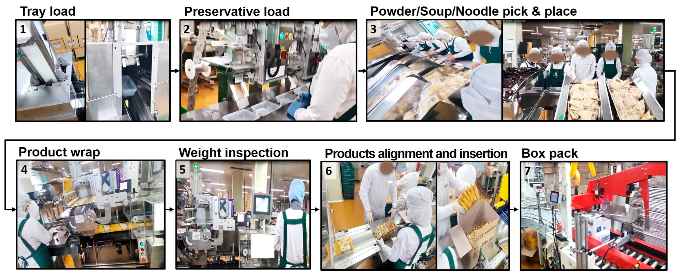
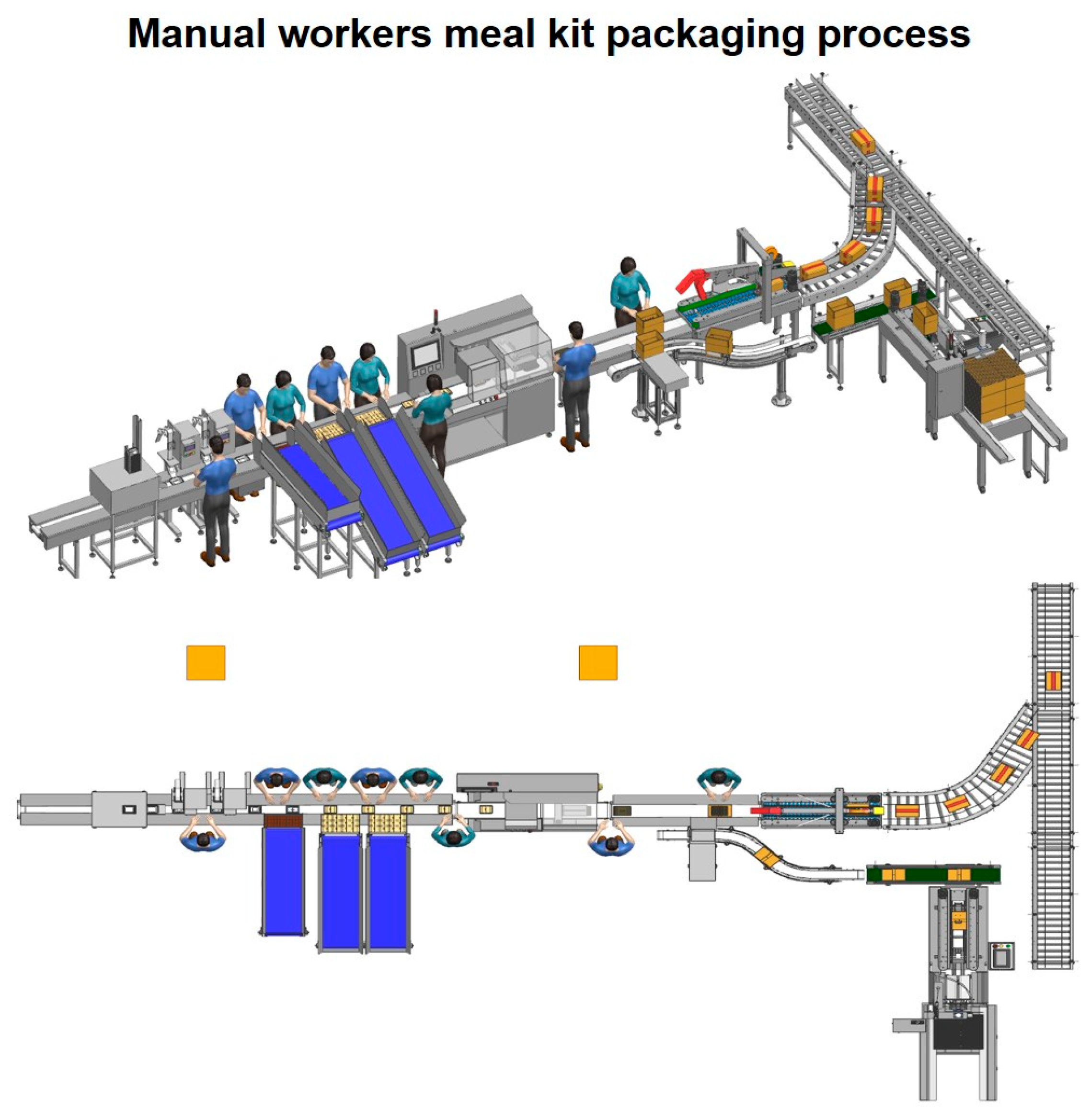
2.1. Analysis of Existing Manual Process of Packaging the Meal Kit Product

First, the existing manual process for meal kit packaging of the representative noodle meal kit product of IGA NATURAL NODDLE (Eumseong-gun, Republic of Korea) was analyzed. The process consists of seven sequential steps. First, trays are individually loaded onto the conveyor belt in a single line (1). Next, an automatic feeder places an antiseptic into each tray (2). Following this, meal kit components, including powder, soup, and noodles, are sequentially placed into the trays by 5 workers (3). Once all components are inserted, the trays are sealed on three sides (4). A weight inspection is then performed to ensure each package meets the specified weight criteria (5). After passing inspection, an operator aligns the products and places them into the designated box, ensuring proper arrangement for the final packaging step (6). Finally, the box, containing all designated products, is automatically taped by the taping machine (7). A series of processes (1–7) is continuously repeated by 8 workers for 8 h a day (Figure 1).

2.2. 3D-Model, Meal Kit, Robot Automation System

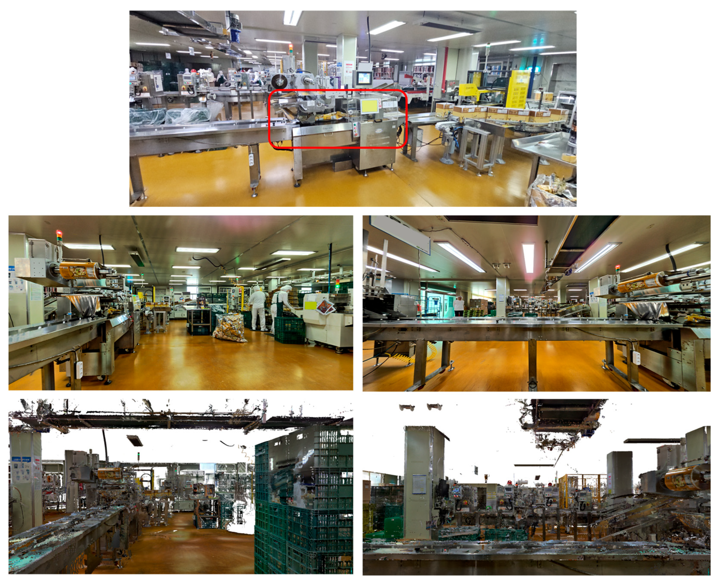
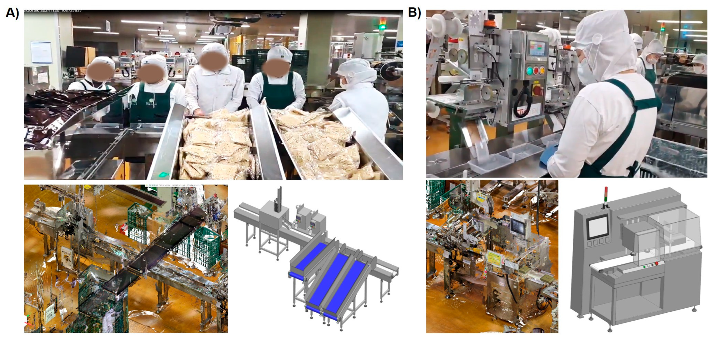
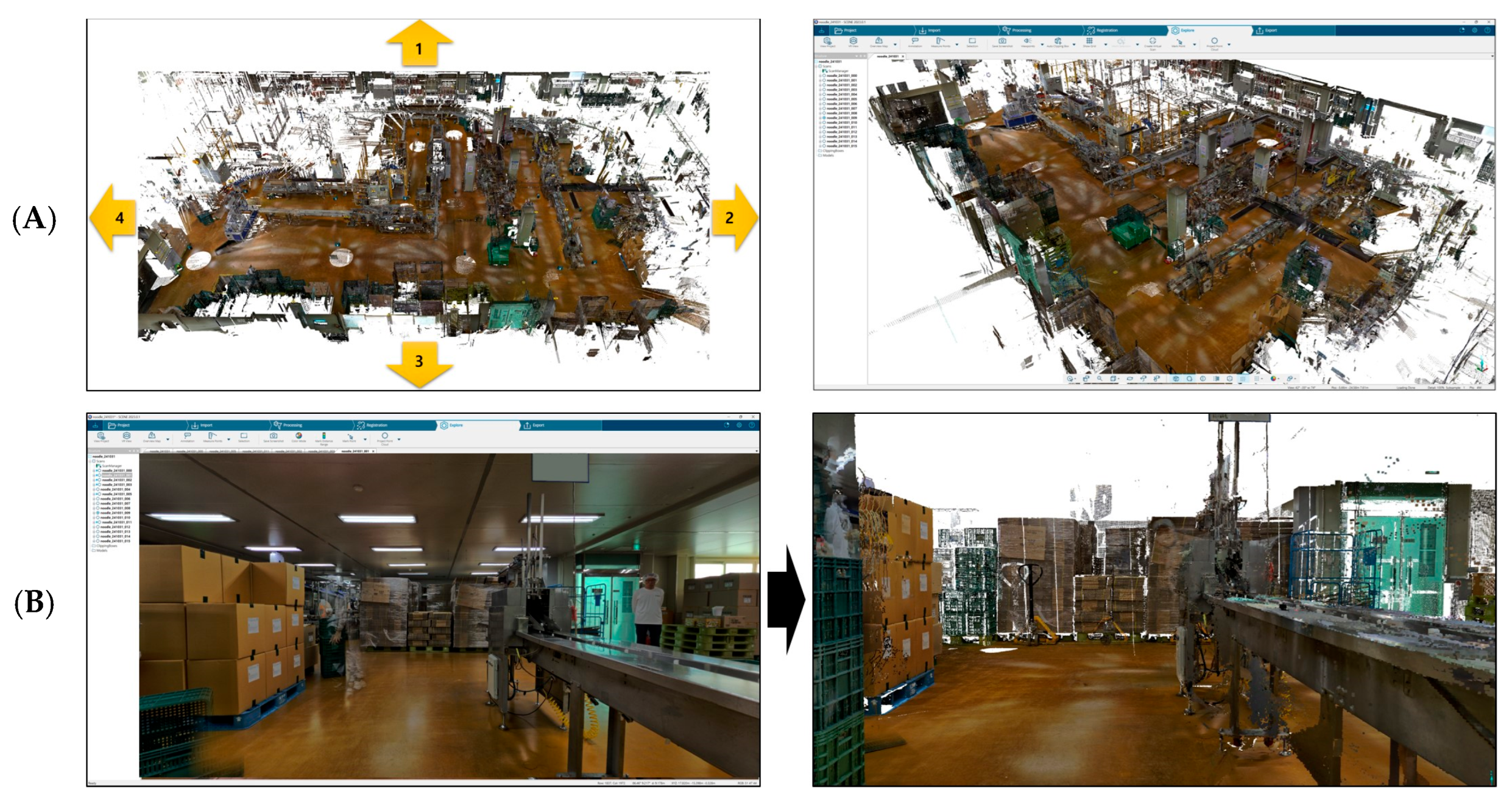
2.2.1. 3D Scanning of Existing Meal Kit Production Site

The purpose of this study was to determine the performance of implementing a robot automation system for the meal kit packaging process by creating a virtual reality, 3D simulation model and map with the manufacturing process of the real world. The major goal of creating a hybrid 3D simulation model was to create a simulation as similar to the real site as possible. Therefore, to create 3D models and design the plant simulation for the meal kit packaging process, a precise scanning of the location of the equipment and application sites in the existing process was implemented [18]. A 3D Lidar scanner (Focus3D-S70-A, FARO, Lake Mary, FL, USA) was used, which provided 3D point cloud data composed of x, y, and z axes along with colormap. The advantage of using a 3D Lidar scanner is that it reduces the time needed to develop a 3D model of the device or location site with less than 2 mm of error [19]. The process of scanning the real site of the existing process site and acquisition of the 3D point cloud data starts with the calibration of the 3D Lidar scanner, including selection of scanning points, registration process, and exporting the dataset. The existing meal kit production site is provided by IGA NATURAL NODDLE company (Eumsung-gun, Republic of Korea). The 3D Lidar scanner applied in this research for scanning the manufacturing site is shown in Figure 2.

2.2.2. 3D Modeling of Existing Meal Kit Packaging Process’s Layout

Based on the scanning result from the 3D Lidar scanner, preprocessing of the 3D Lidar scanned data includes noise removal and is exported in the Pointtools POD (*.POD) format which contains 3D point clouds composed of x, y, and z coordinates with color information. To verify the usefulness and performance of the custom-designed robot automation system for the meal kit packaging’s assembly line, the 3D model of machinery needs to be designed in order to construct a simulation model where the manual working process is replaced with robots. 3D modeling of existing devices, such as the packaging device or conveyor belt where the manufacturer gives a library, was customized using SOLIDWORKS Premium, computer-aided design (CAD) software (SOLIDWORKS 2023 SP 4.0, Dassault Systems, Waltham, MA, USA). The devices for which the manufacturer does not provide a library were modeled based on imported 3D point cloud data, which was then converted into a computer-aided design (CAD) file by creating a surface mesh and was then ready to be exported for future 3D simulation design. Next, the 3D modeling of devices was imported to Siemens NX modeling software (V2201, SIEMENS Inc., Munich, Germany) to develop the meal kit assembly line’s layout. Figure 3A represents workers manually loading each meal kit product onto the tray transfer by the conveyor belt and the 3D-scanned point cloud data with the preprocessed 3D modeling of the loading and transfer process. Figure 3B represents a worker aligning each of the loaded meal kit products in the tray prior to the packaging process to reduce the number of defects and 3D modeling of the packaging equipment.

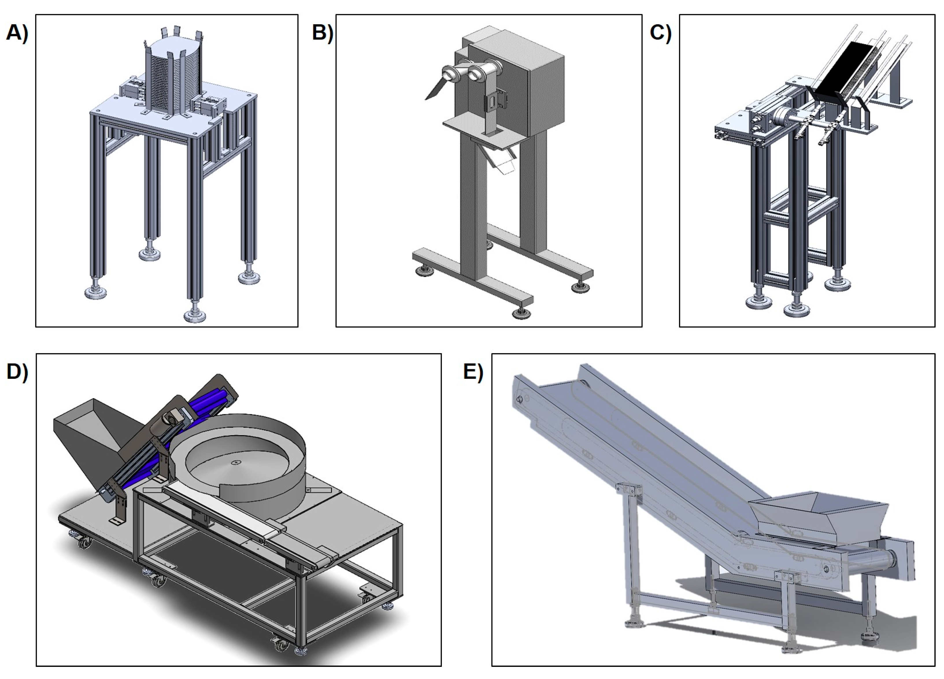
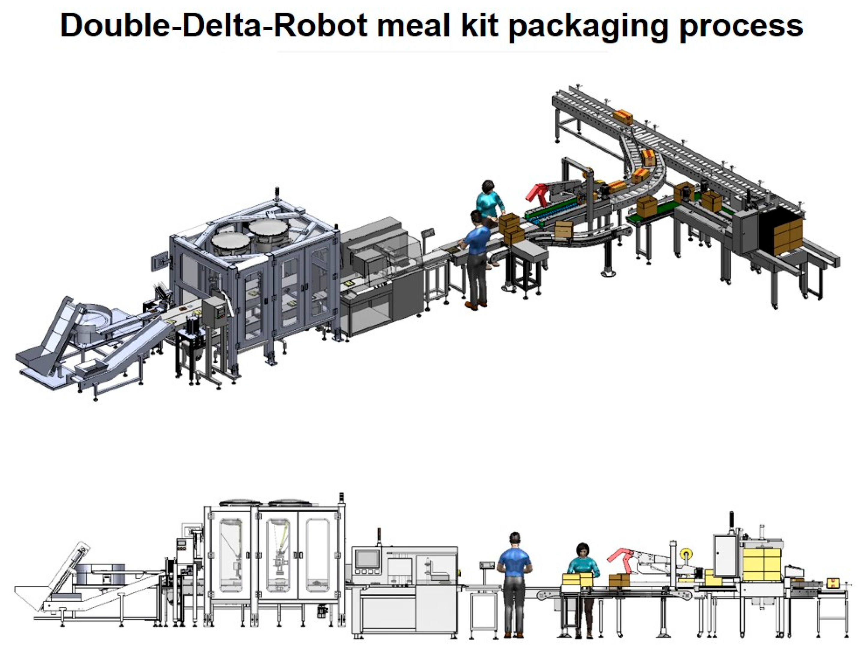
2.2.3. 3D Modeling of Robot-Implemented Meal Kit Packaging Process

In this study, we developed a framework for the 3D simulation of the meal-kit-packaging robot automation system by not only implementing robots but also automating packaging devices to determine the optimal layout in order to improve performance as well as reduce the number of workers. In this study, we designed the robot automation system composed of a delta robot (IRB360X800WD4D, ABB, Zurich, Switzerland) with a custom-made frame (Figure 4A,B). A pneumatic rotational gripper, which is attached to the moving platform of the delta robot for the pick-and-place process of individual meal kit items, was custom-designed to be configured with two types of gripper vacuum pads: sponge cup and suction cup (Figure 4C). In addition, 5 different types of automatic, individual meal-kit-product feeders (Figure 5) were designed and implemented in 3D simulation. The individual meal kit items can be classified into two types: noodles, which are relatively heavy with an uneven surface, and the others (powder and sauce), which are light with an even surface. The sponge-type pad attached to the custom-designed gripper can pick the noodles, while the suction-cup-type pad can pick the powder and sauce.
As mentioned above, there are 5 workers deployed in loading each meal kit into the tray which requires an automatic feeder to replace the workers. To develop a robot automation system, manual loading of the meal kit items to the conveyor can be replaced by the automation devices. There are five automatic feeding devices that we designed for each meal kit item as shown in Figure 5.

2.3. Development of Robot-Automated 3D Simulation of Meal Kit Packaging Process

As mentioned above, plant simulation is an emerging method for engineers to design an assembly line and test system performance before full-scale implementation [8]. By developing an assembly of a 3D-plant simulation model, manufacturers can determine the optimal workflow as well as decrease bottleneck processes. In addition, it virtually allows for the evaluation of differences for different assembly line layouts such as manual process vs. robot-implemented process. This results in a reduced modification time and resource usage without the need for a physical prototype in an efficient way [6,7,8,9].
To develop a framework of 3D plant simulation of the meal kit robot automation system, there are several steps. First, 3D modeling of the robot and devices are modeled by forward engineering using the CAD program and reverse engineering using 3D Lidar scanning. Designed 3D models are then imported to SIEMENS NX software for preprocessing, including alignment and noise reduction to create the initial meal kit assembly layout. The 3D assembly layout developed from NX software is exported to the robot simulation program. In the robot simulation program, the kinematics of the robot and the constraints and initial setting of the 3D simulation are defined and the cycle time of unit processes are calculated. The 3D simulation is exported to the SIEMENS plant simulation to calculate the performance of the developed robot automation such as utilization rate or throughput.
In this research, a 3D simulation for the meal-kit-packaging robot automation is designed using SIEMENS Tecnomatix Process Simulate (TPS) V2301 (SIEMENS Inc., Munich, Germany) for tasks such as robot kinematic programming, cycle time planning, and human operations. The 3D plant simulation results are then analyzed using SIEMENS Plant Simulation (V22.0.1, SIEMENS Inc., Munich, Germany) to evaluate the efficiency and performance of the processes. The generated full process of the 3D plant simulation model of the robot, robot gripper, and rest of the production assembly machinery, such as the conveyor and automatic, individual meal-kit-product feeders, are imported to SIEMENS TPS for assembly. To develop the full process of 3D plant simulation, the initial setting needs to be configured. The single-delta-robot-implemented, for the manual existing process, and double-delta-robot-implemented robot automation system’s availabilities, which represent the percentage of time the machinery performance capability is at 95% in a shift calendar with 5 days and 40 h per week as the operation setting, was configured. In addition, the mean time to repair (MTTR) which is the minimum time to reset all the devices to the original setting was set as 15 min [20]. The detail configuration of the 3D plant simulation and kinematic setting for the delta robot, gripper, automatic feeders, and rest of devices applied in the novel design of this meal-kit-packaging assembly line is explained as follows.

Application of Delta Robot to Novel, Hybrid 3D Simulation of the Assembly Line for Robot Automation Packaging of Meal Kits

In this research, we applied a delta robot to replace the manual process of individual meal kit loading into a tray to create a developed robot automation system. The delta robot is a three-armed, parallel robot which allows for high acceleration and a large range of motion with precise executing of pick-and-place motion [21]. To generate a hybrid, meal kit, 3D simulation model, a kinematic of the delta robot, to generate a trajectory for the pick-and-place movement, should be implemented in the 3D simulation software. After configuration of the production machinery, the kinetic mechanisms of the implemented-robot and individual meal kit pick-and-place gripper joint are defined. To define the robot kinematic, we set the initial physical characteristics of the delta robot such as the length of the arm, location of the rotation joint, the distance from the end of the moving platform of the delta robot to the end of gripper, etc. To create a robot trajectory, we applied the inverse-position kinematic of the delta robot [22]. There are two major revolute-input delta robot kinematics: inverse-position kinematic and forward-position kinematic. The inverse-position kinematic uses x, y, and z coordinates as inputs to get 3 rotation angles, whereas the forward-position kinematic uses three rotation angles as inputs to get the position value [23].
t h e   o r i g i n   o f   P   w h e r e   P = b a s e   f r a m e
P p = x   y   z T
Θ = θ 1   θ 2   θ 3 T
The delta robot’s inverse position kinematics (IPK) is accomplished by using the three constraint equations applied to a vector loop-closure equation. The three independent, scalar IPK equations are of the form which can solved using the Tangent Half-Angle Substitution:
E i cos θ i + F i sin θ i + G i = 0   i = 1 ,   2 ,   3
θ i = 2 t a n 1 ( t i )
After importing the 3D model of the delta robot to the Siemens software, the defined, delta-robot kinematic is shown in Figure 6. We created a robot simulation using the kinematic model to pick individual meal kit items and place them on the tray—as shown in figure below—and repeat for each item.
In addition, after defining the robot kinematic, a rotational gripper mounted on the end effector of the delta robot, translation direction of the end effector as well as the motion speed and motion type of point to point are applied, and the trajectory is also defined. Figure 7 represents the single delta robot and mounted gripper motion generated for the simulation. The process of the individual meal kit product for pick-and-place motion starts with picking the transferring noodle on the conveyor, the gripper rotating 90 degrees, picking the transferring powder on the conveyor, picking the soup transferring on the conveyor, moving to the next conveyor belt and each transfer tray, placing the powder and soup in the tray, the gripper rotating 90 degrees, and placing the noodle in tray, simultaneously.
The developed 3D simulation of the single-delta-robot-implemented meal kit packaging process is constructed with 5 major, automatic, individual meal kit product feeders, which is performed by works in the manual packaging process. The machineries, such as the automatic feeder (Figure 8A), tray loader (Figure 8B), and pillow packaging machine’s characteristic and parameters (Figure 8C), are defined. For example, the size, moving path direction, and speed of the pillow packaging machine are defined as shown in Figure 8.
Next, 3D simulation, which applied two delta robots for the individual meal kit’s pick-and-place process, is shown in Figure 9 to determine the optimal assembly line for meal kit packaging to achieve the best KPIs. The robot and gripper kinematic and motion are defined in the same manner as the single-delta-robot-implemented 3D simulation. The motion of the first delta-robot-based 3D simulation starts with picking the powder and soup and moving it beside the conveyor belt to placing the powder and soup in the tray. Second, the delta robot’s motion is to pick and place the noodle in the tray.

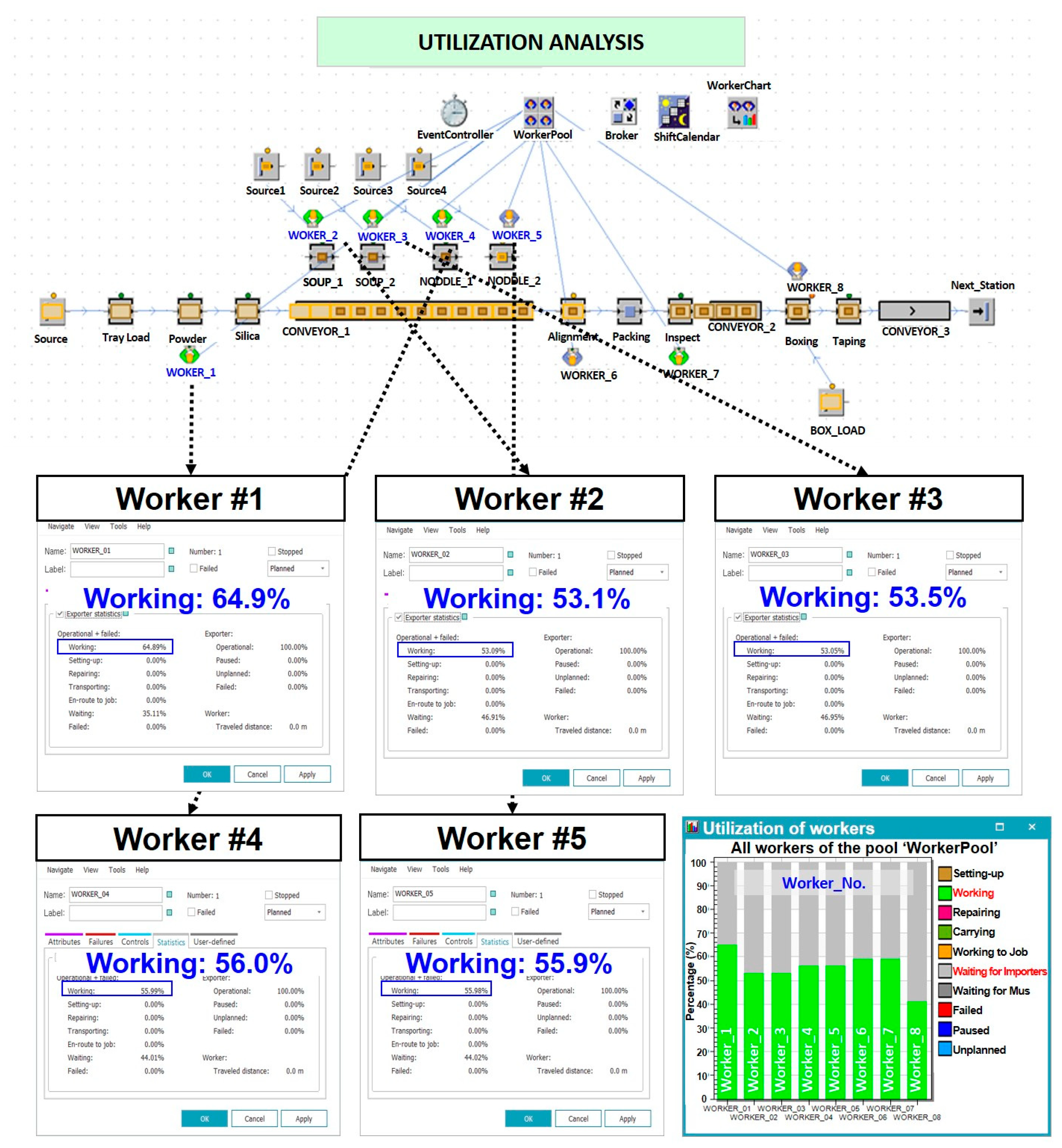
2.4. Performance Analysis of Robot Automation System

To analyze the performance of the 3D simulation, three major KPIs are applied which are throughput, utilization rate, and number of employee. First, the manual worker’s manufacturing process and robot-automation manufacturing process of three KPIs are derived. For the manual process, throughput is calculated based on manually hand-written-production record data where the maximum number of production value is derived from one month of recorded data, and the number of workers is determined by recording the production site. Next, the utilization rate, which is defined as the ratio of each machinery’s robot operation time compared to how long it could be used while the manufacturing factory operates, is determined. In this study, we set the maximum operation time of the robot as the actual, planned work time of workers for each day [24]. Lastly, the robot cycle time, which is the total time required for a robot to complete one full operation, from the start of a task to the beginning of the next identical task, is extracted.

3. Results and Discussion

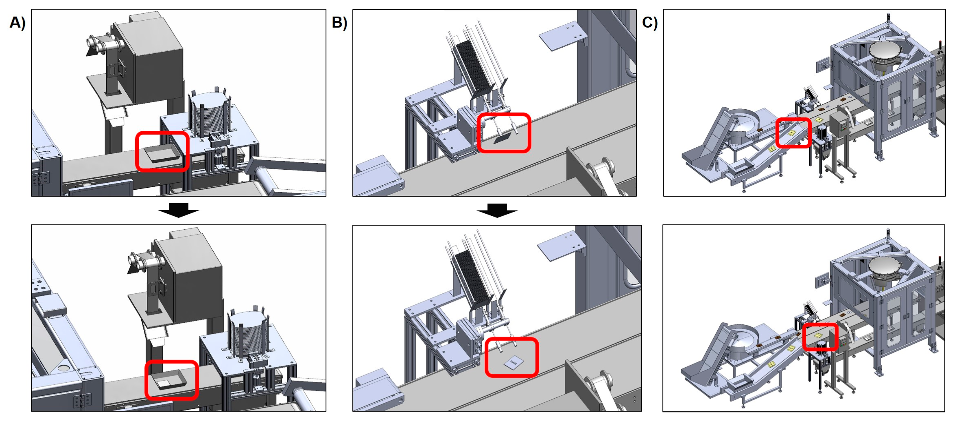
3.1. Result of 3D Scanning of Existing Production Site

As shown in Figure 10, the results of 3D scanning the existing meal-kit-packaging production line are acquired. The 3D point cloud with 2D, RGB image data are acquired from a total of 15 scanning sites to scan the entire real-world manufacturing site in order to develop a hybrid 3D simulation model by mapping with 3D Lidar scanned point clouds. From the 3D Lidar scanner program, the scanned data are imported and preprocess; for example, colorization, filter, and find targets are applied. After preprocessing the dataset, the automatic registration process is applied to align each scanned dataset as shown in Figure 10A. As a result of the automatic registration process, a minimum of 0.5 mm to a maximum of 1.3 mm of registration error and a minimum overlap of 47.7% occurred.
After the preprocessing and registration process, aligned 3D-scanned data are exported with the format of Pointtools POD (*.POD) as shown in Figure 10A. In addition, the 3D-scanned point cloud data are compared with the real site using the 2D-captured image (Figure 10B).

3.2. Result of Manual Meal Kit Packaging Process

As shown in Figure 11, the existing manual meal kit packaging process’s assembly line is 3D-modeled and run in a 3D simulation to determine three major KPIs. There are total of eight workers standing beside the assembly line to load the individual meal kit products into the moving conveyor, to align each meal kit product, and to incase the packaged product into the box. Specifically, there are five workers who put each individual meal kit product into the transferred tray. The utilization rate of each of the five workers showed 64.9%, 53.1%, 53.1%, 56.0%, and 55.9%, respectively, which could lead to the accumulation of overload and fatigue due to continuous work during 8 h of working time each day (Figure 12). In addition, the 3D plant simulation showed the throughput of 2112 ea/h.

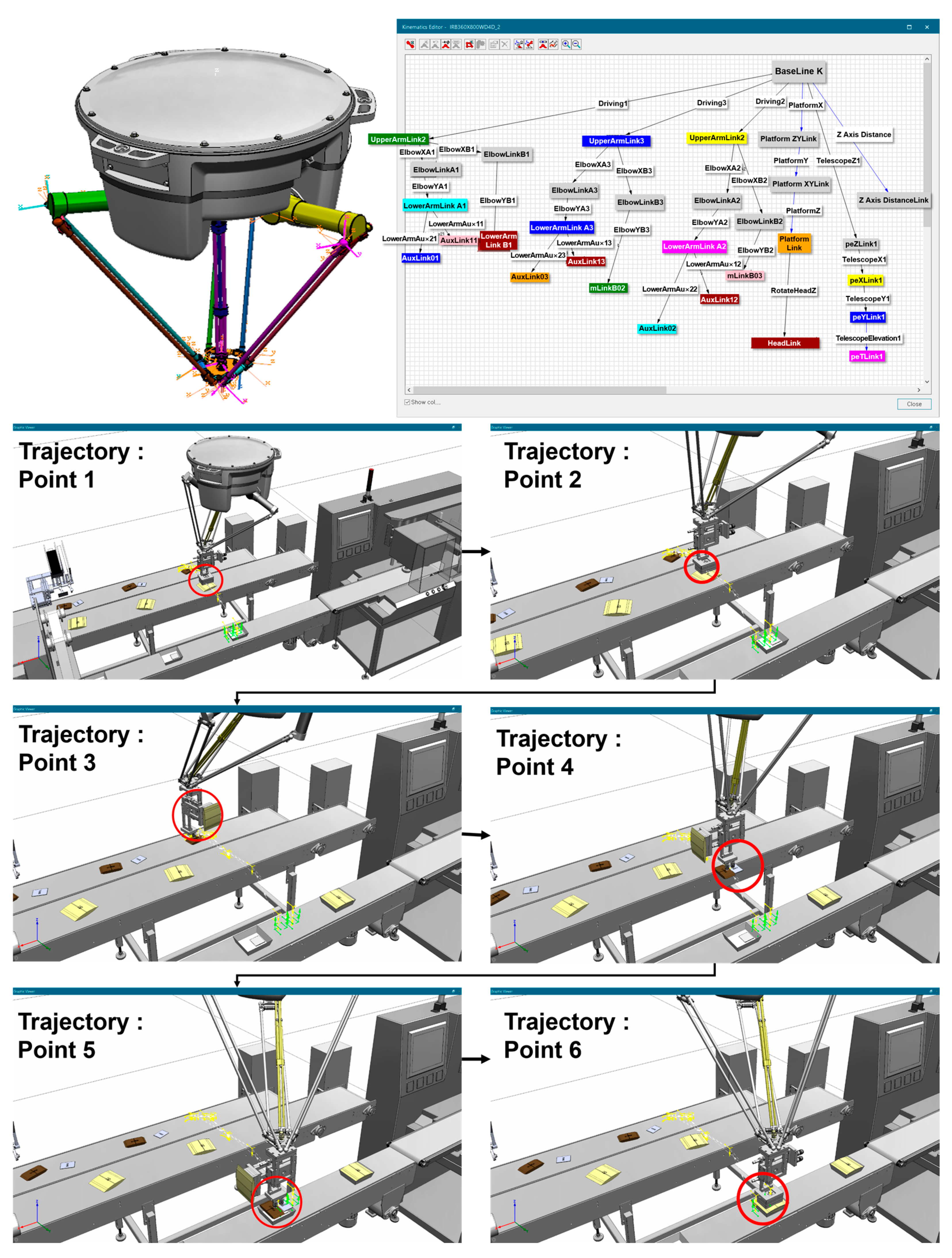
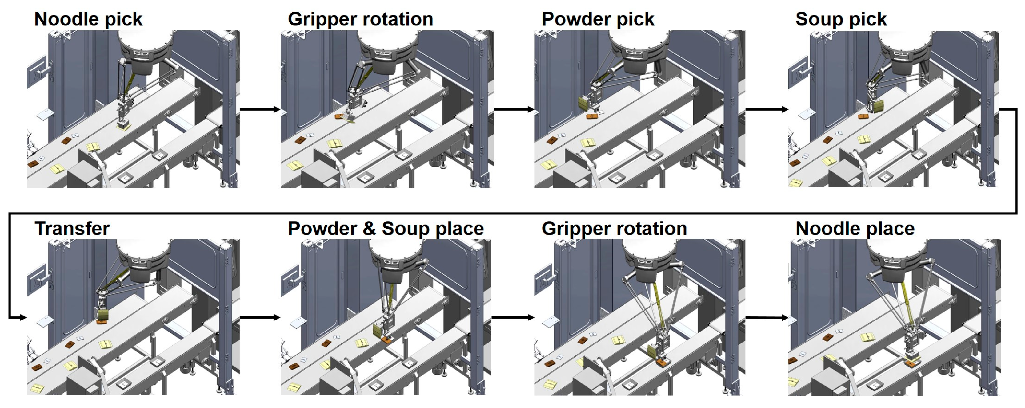
3.3. Result of Single-Delta-Robot-Implemented Meal Kit Packaging Process

As mentioned above, there are five workers who put each individual meal kit product into the tray for one packaged meal kit product. Therefore, in this study, we developed two cases of 3D-plant simulation models of robot automation systems to replace the meal kit packaging process. To accomplish higher throughput, the delta robot and meal kit automatic feeders were implemented into the same process and analysis. First, the 3D-plant simulation model was designed by applying a single delta robot and automated loading devices to replace five workers for the loading of each meal kit product prior to the packaging process (Figure 13). In addition, Figure 13 shows a virtual, single-delta-robot, meal-kit-packaging, 3D simulation model mapped with 3D-scanned models.
The 3D plant simulation of the single-delta-robot-implemented model showed a utilization rate of 99% and throughput of 1510 ea/h. The cycle time showed 2.36 s for the process of picking and placing each meal kit product into the tray based on a developed robot kinematic model. The utilization rate of 99% represents the delta robot working without delay or rest time. However, it is a very high number which might cause robot failure and shorten its lifespan. In addition, the number of product produced per hour is approximately 71.5% of the manual working process (Figure 14). In addition, the number of workers is reduced from eight to two.

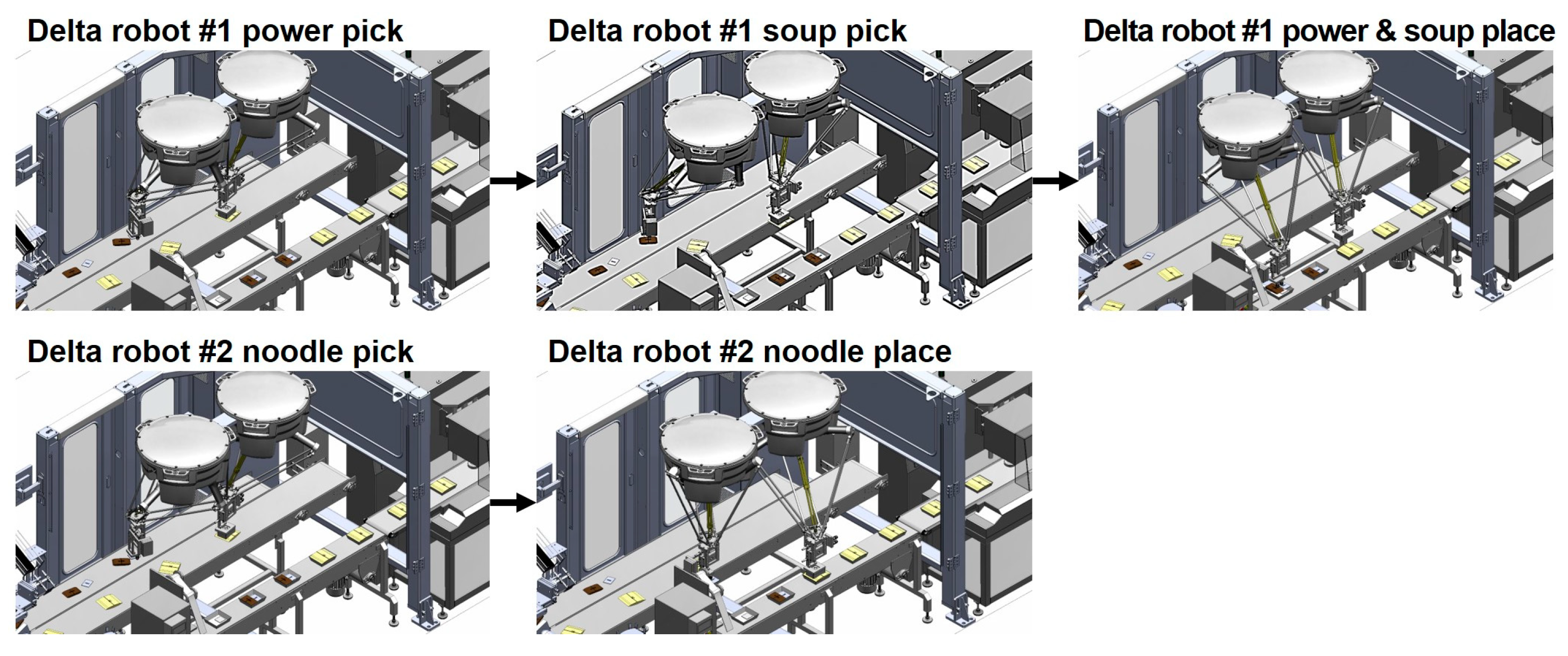
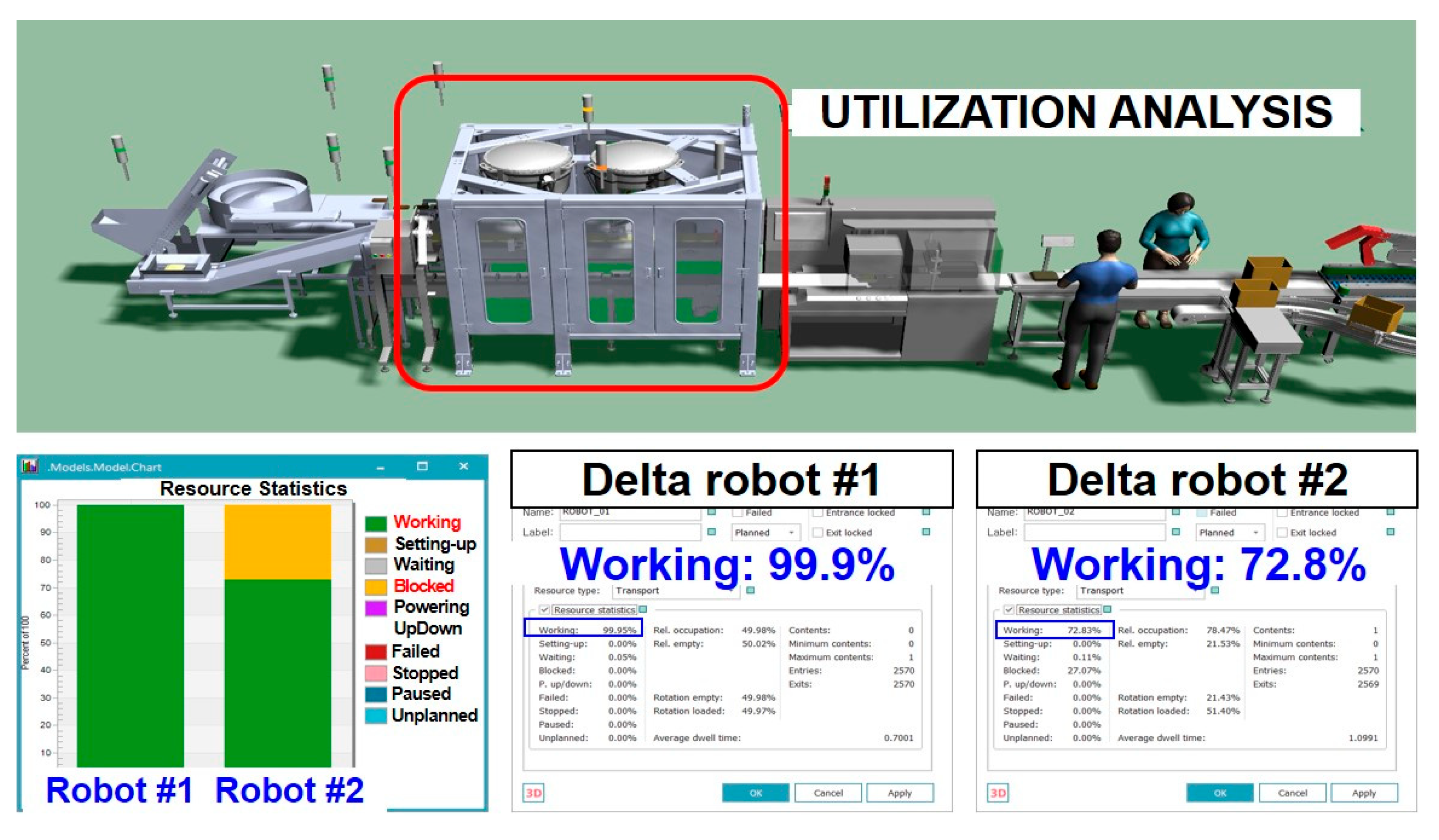
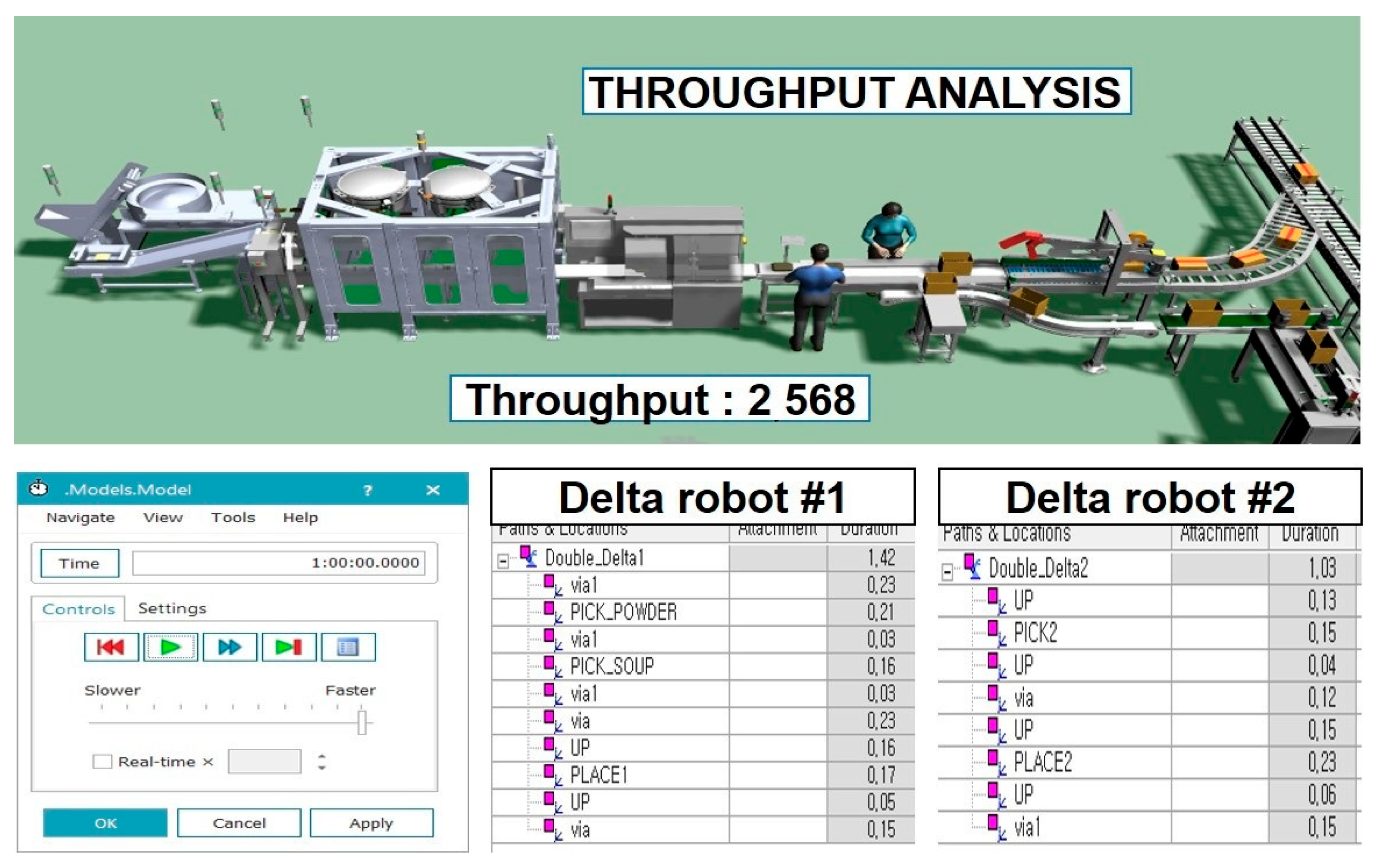
3.4. Result of Double-Delta-Robot-Implemented Meal Kit Packaging Process

Second case of 3D-plant simulation model is designed by applying two delta robots to replace five workers for loading each meal kit product prior to packaging process. Representative double delta implemented meal kit packaging process 3D plant simulation is shown in Figure 15.
The 3D plant simulation of the double-delta-robot-implemented model showed utilization rates of 98% and 72.8% for delta robot #1 and #2, respectively (Figure 16). In addition, the number of product produced per hour was 2586 (Figure 17) with a cycle time of 1.03 s and 1.42 s for delta robot #1 and #2, respectively. The number of worker replaced by implementing the robot automation system reduced from eight to two (Table 1).

4. Discussion

In the real world of individual meal kit packaging processes, the meal kit product is composed of a number of individual meal kit items such as sauce, vegetable, meat, noodle, etc. For each final meal kit product, the meal kit item size, type, number, and method of packaging is varied which makes the meal kit packaging process complex. Based on these high-variant parameters, the hybrid 3D simulation is required, while changing the manufacturing layout, to apply the robot automatic system in order to reduce the cost and time of optimizing a newly designed manufacturing layout. In addition, to achieve the number of products produced each day by workers by using the robot automation system, 3D simulation can give the output if the robot automation system is used to improve performance prior to the actual new equipment installation.
For the simulation, the 3D scanning technique offers many advantages, including faster data acquisition, higher precision, non-contact measurement, reduced human error, and cost-effectiveness. These benefits make it particularly well-suited for capturing complex geometries and generating accurate 3D models efficiently, while also enhancing the reliability of the resulting models [25,26].
In the manual process, the majority of workers (five out of eight) was involved in the meal kit components’ insertion process in the tray to achieve the target set for order-based production. The result of the 3D simulation showed that the average utilization rate of the manual packaging process was 56.58%. The relatively low utilization rate of manual work may be attributed to process inefficiencies caused by waiting times, worker fatigue, variability, and the burden of repetitive tasks. Thus, we considered replacing five workers in the most labor-intensive process with the single or double delta robot and five automatic individual components feeders. In addition, a pneumonia rotational gripper of the delta robot was designed that can pick various types of meal kit components.
The throughput of the meal kit packaging process implemented with a single delta robot is only about 68.3% compared to that of manual work, even though it has a very high utilization rate of 99.9%. It was difficult for the single delta robot system to reach the throughput of the manual process due to the relatively long cycle time, as it had to sequentially pick and place three different components. Therefore, the single delta robot system requires more than two workers to improve the throughput.
The throughput of the process implemented with the double delta robot was approximately 121.6% compared to the manual process, with utilization rates of 98.0% and 78.5%, respectively. The utilization rate and one cycle time of the delta robot #1 for gripping two components (source and power) were 98.0% and 1.42%. The robot #2, designed for gripping one component (noodle), showed a lower utilization rate and cycle time compared to robot #1, with 78.5% and 1.03 s, respectively. Thus, since all components are placed on the tray in a cycle of 1.42 s, with two robots, the cycle time can be approximately 1.66 times faster, and the throughput can be 1.7 times greater compared to using just one robot. The increased throughput suggests that robotic implementation can significantly reduce bottlenecks and improve working speed in meal kit packaging process. Additionally, if the number of meal kit components increases, it can be considered that there is a possibility of utilizing delta robot #2, which has a remaining utilization rate of 21.5%.
There are several unit manufacturing processes for meal kit manufacturing processes. To determine the full effects of a robot automation system, it is important to develop 3D simulation of not only unit processes but also full manufacturing processes such as box incasing or palletizing unit processes. In a future study, a hybrid-robot-automated 3D simulation can be expanded by adding other important unit processes such as a box incasing unit process to develop a final simulation model for evaluating the performance of the entire process.

5. Conclusions

A data-driven 3D simulation for robotic automation of the most labor-intensive packaging process in meal kit production was developed based on plant simulation. The workflow and environments of the existing manual process were analyzed. An existing production site was scanned using a 3D Lidar scanner to create 3D models and design the initial assembly layout. Two types of 3D simulation models, implemented with a single or double delta robot, were designed to determine the optimal robot-automated packaging process. Key performance indicators for the simulation models of the manual and two robot automation systems were analyzed. The throughputs of the manual, single delta robot and double delta robot models were 2112, 1510, and 2568 ea/h, respectively. The single robot system achieved only 68.3% of the throughput of the manual process, which is attributed to a cycle time of 2.36 s for picking and placing all components. On the other hand, the cycle time of the double robot system was 1.66 times faster, and the throughput was 1.7 times greater compared to single robot system. The developed 3D simulation model for the meal kit packaging system demonstrates the potential of robotic automation in addressing the labor shortage issue as well as improving production efficiency.
In this study, a framework of a 3D plant simulation for a meal kit packaging process was suggested because it involves handling multiple components, making it highly complex and labor-intensive and the most challenging process. In detail, a simulation-based approach utilizing TPS was conducted to introduce a robot automation system replacing workers of a meal kit packaging line in consideration of the surrounding equipment. The simulation was performed based on analysis of the workflow and environment of the manual process. The two plant simulation models for the automation processes using one or two delta robots were developed. A performance evaluation, such as productivity and the utilization rate for the improvement effect, was investigated by comparing the manual process and robot automation packaging process.

Author Contributions

Conceptualization, T.H.K.; methodology, T.H.K.; software, B.I.G.; validation, T.H.K., A.-N.K. and B.I.G.; formal analysis, T.H.K. and A.-N.K.; investigation, T.H.K.; resources, T.H.K.; data curation, A.-N.K.; writing—original draft preparation, T.H.K. and A.-N.K.; writing—review and editing, T.H.K. and A.-N.K.; visualization, T.H.K. and A.-N.K.; supervision, T.H.K.; project administration, K.H.K.; funding acquisition, K.H.K. All authors have read and agreed to the published version of the manuscript.

Funding

This work was supported by the Robotics Industrial Technology Innovation Program (RS-2024-00423566, GN245200-02) funded by the Ministry of Trade, Industry and Energy (MOTIE) of Korea.

Institutional Review Board Statement

Not applicable.

Informed Consent Statement

Not applicable.

Data Availability Statement

Data are available from the authors upon request.

Acknowledgments

The authors thank Sang Shin Kim (Myeongsung, Busan, Republic of Korea) and Kyung Hyuk Baek (IGA NATURAL NOODEL, Eumseong-gun, Republic of Korea) for their support with the data management and setup for this manuscript.

Conflicts of Interest

Author Byoung Il Gu was employed by the company KyoungHee Corporation. The remaining authors declare that the research was conducted in the absence of any commercial or financial relationships that could be construed as a potential conflict of interest.

Abbreviations

The following abbreviations are used in this manuscript:
HMRHome Meal Replacement
TPSTecnomatix Process Simulate
CADComputer-Aided Design
KPIKey Performance Indicators

References

  1. Bumbudsanpharoke, N.; Ko, S. Packaging technology for home meal replacement: Innovations and future prospective. Food Control 2022, 132, 108470. [Google Scholar] [CrossRef]
  2. Rha, J.Y.; Lee, H.; Kim, S.; Nam, Y. A study on the relationship between purchases of meal kits and home meal replacements. Nutr. Res. Pract. 2024, 18, 425–435. [Google Scholar] [CrossRef] [PubMed]
  3. Mahalik, N.P. Processing and packaging automation systems: A review. Sens. Instrum. Food Qual. Saf. 2009, 3, 12–25. [Google Scholar] [CrossRef]
  4. Mahalik, N.P.; Yen, M. Extending fieldbus technology to food processing industry: A review. Comput. Stand. Interfaces 2009, 31, 586–598. [Google Scholar] [CrossRef]
  5. Bader, F.; Rahimifard, S. Challenges for industrial robot applications in food manufacturing. In Proceedings of the 2nd International Symposium on Computer Science and Intelligent Control, Stockholm, Sweden, 21–23 September 2018; pp. 1–8. [Google Scholar]
  6. Mahmoodi, E.; Fathi, M.; Tavana, M.; Ghobakhloo, M.; Ng, A.H. Data-driven simulation-based decision support system for resource allocation in industry 4.0 and smart manufacturing. J. Manuf. Syst. 2024, 72, 287–307. [Google Scholar] [CrossRef]
  7. Florescu, A. Digital twin for flexible manufacturing systems and optimization through simulation: A case study. Machines 2024, 12, 785. [Google Scholar] [CrossRef]
  8. Soori, M.; Arezoo, B.; Dastres, R. Digital twin for smart manufacturing, A review. Sustain. Manuf. Serv. Econ. 2023, 2, 100017. [Google Scholar] [CrossRef]
  9. Leng, J.; Wang, D.; Shen, W.; Li, X.; Liu, Q.; Chen, X. Digital twins-based smart manufacturing system design in Industry 4.0: A review. J. Manuf. Syst. 2021, 60, 119–137. [Google Scholar] [CrossRef]
  10. Srasrisom, K.; Srinoi, P.; Chaijit, S.; Wiwatwongwana, F. Improvement of an Automated CAN Packaging System Based on Modeling and Analysis Approach through Robot Simulation Tools. Int. J. Robot. Autom. 2020, 9, 178–189. [Google Scholar] [CrossRef]
  11. Jha, A.; Soni, M.; Suhaib, M. Simulation and Kinematic Analysis of KUKA KR5 Arc Robot. In IOP Conference Series: Materials Science and Engineering; IOP Publishing: Bristol, UK, 2021; Volume 1149, p. 012005. [Google Scholar]
  12. Gui, W.; Zhou, F.; Tang, F. Research on Motion Simulation of Stacking Robot Workstation Based on RobotStudio. In Proceedings of the 2023 IEEE 3rd International Conference on Power, Electronics and Computer Applications (ICPECA), Shenyang, China, 29–31 January 2023; IEEE: Piscataway, NJ, USA, 2023; pp. 301–305. [Google Scholar]
  13. Vasudevan, S.; Mekhalfi, M.L.; Blanes, C.; Lecca, M.; Poiesi, F.; Chippendale, P.I.; Lastra, J.L.M. Robotics and Machine Vision for Primary Food Manipulation and Packaging: A Survey. IEEE Access 2024, 12, 152579–152613. [Google Scholar] [CrossRef]
  14. Afizul, N.A.; Selimin, M.A.; Pagan, N.A.; Ng, K.Y. Modelling an Assembly Line Using Tecnomatix Plant Simulation Software. Res. Manag. Technol. Bus. 2024, 5, 1048–1055. [Google Scholar]
  15. Janekova, J.; Fabianova, J.; Kadarova, J. Optimization of the automated production process using software simulation tools. Processes 2023, 11, 509. [Google Scholar] [CrossRef]
  16. Fedorko, G.; Molnár, V.; Strohmandl, J.; Horváthová, P.; Strnad, D.; Cech, V. Research on Using the Tecnomatix Plant Simulation for Simulation and Visualization of Traffic Processes at the Traffic Node. Appl. Sci. 2022, 12, 12131. [Google Scholar] [CrossRef]
  17. Fusto, C.; Longo, F.; Muraca, A.; Rudi, L.; Timpani, T.; Veltri, P. Enhancing Efficiency in the Food Industry: A Simulation Model for Optimizing Production Processes. In Proceedings of the 9th International Food Operations & Processing Simulation Workshop (FOODOPS 2023), Athens, Greece, 18–20 September 2023. [Google Scholar]
  18. Wang, J.; Yi, T.; Liang, X.; Ueda, T. Application of 3D Laser Scanning Technology Using Laser Radar System to Error Analysis in the Curtain Wall Construction. Remote Sens. 2022, 15, 64. [Google Scholar] [CrossRef]
  19. Di Stefano, F.; Chiappini, S.; Gorreja, A.; Balestra, M.; Pierdicca, R. Mobile 3D scan LiDAR: A literature review. Geomat. Nat. Hazards Risk 2021, 12, 2387–2429. [Google Scholar] [CrossRef]
  20. Kim, T.H.; Byoung, G.; Kwon, K.H.; Kim, A.N. Plant Simulation for Robot Automation System of Deep-Frying Process of Kimbugak. Food Sci. Biotechnol. 2025, 34, 503–514. [Google Scholar] [CrossRef]
  21. Cheng, H.; Li, W. Reducing the frame vibration of delta robot in pick and place application: An acceleration profile optimization approach. Shock Vib. 2018, 2018, 2945314. [Google Scholar] [CrossRef]
  22. Kansal, S.; Mukherjee, S. Vision-Based Kinematic Analysis of the Delta Robot for Object Catching. Robotica 2022, 40, 2010–2030. [Google Scholar] [CrossRef]
  23. Gholami, A.; Homayouni, T.; Ehsani, R.; Sun, J.Q. Inverse Kinematic Control of a Delta Robot Using Neural Networks in Real-Time. Robotics 2021, 10, 115. [Google Scholar] [CrossRef]
  24. Aliev, K.; Antonelli, D.; Awouda, A.; Chiabert, P. Key performance indicators integrating collaborative and mobile robots in the factory networks. In Proceedings of the Collaborative Networks and Digital Transformation: 20th IFIP WG 5.5 Working Conference on Virtual Enterprises, PRO-VE 2019, Turin, Italy, 23–25 September 2019; Springer International Publishing: New York, NY, USA; pp. 635–642. [Google Scholar]
  25. Frohlich, C.; Mettenleiter, M. Terrestrial laser scanning–new perspectives in 3D surveying. Int. Arch. Photogramm. Remote Sens. Spatial Inf. Sci. 2004, 36, W2. [Google Scholar]
  26. Yilmaz, A.; Sumer, E.; Temeltas, H. A precise scan matching based localization method for an autonomously guided vehicle in smart factories. Robot. Comput. Integr. Manuf. 2022, 75, 102302. [Google Scholar] [CrossRef]
Figure 1. Sequence of meal kit packaging process in the actual manufacturing environment.
Applsci 15 04116 g001
Figure 2. Meal kit production site along with 3D-Lidar-scanner-scanned site.
Applsci 15 04116 g002
Figure 3. Real meal kit production site’s image and 3D-Lidar-scanned point cloud data with each production equipment. (A) represents the loading of each meal kit product to the conveyor belt by workers; (B) represents the loading of each meal kit product to the tray for packaging process.
Applsci 15 04116 g003
Figure 4. 3D modeling of delta robot with frame and gripper applied to the pick-and-place operation. (A) Delta robot frame; (B) delta robot; (C) pneumatic rotational gripper.
Applsci 15 04116 g004
Figure 5. 3D modeling of assembly line for automatic loading of individual meal kit products. (A) Automatic tray loader; (B) automatic antiseptic feeder; (C) pneumatic soup feeder; (D) rotary feeder; (E) elevated conveyor.
Applsci 15 04116 g005
Figure 6. Representative generated trajectory of single delta robot for pick-and-place process in 3D simulation.
Applsci 15 04116 g006
Figure 7. Representative 3D simulation of single delta robot and peripheral machinery for meal kit packaging process.
Applsci 15 04116 g007
Figure 8. Configuration and parameters for automatic feeder or loader. (A) Tray loading to conveyor; (B) pneumatic, soup-feeder rotation and drop point to conveyor setting; (C) transfer time for elevated conveyor.
Applsci 15 04116 g008
Figure 9. Representative 3D simulation of double delta robot and peripheral for meal kit packaging process.
Applsci 15 04116 g009
Figure 10. Result of 3D Lidar scanning of existing meal kit production site. (A) 3D point cloud data extracted from 3D Lidar scanner program; (B) comparison of RGB image to scanned 3D point cloud data.
Applsci 15 04116 g010
Figure 11. 3D plant simulation for manual meal kit packaging process.
Applsci 15 04116 g011
Figure 12. Representative utilization analysis result of 5 workers for manual meal kit packaging process.
Applsci 15 04116 g012
Figure 13. Representative single-delta-robot-implemented designed 3D simulation and mapped with 3D-scanned model.
Applsci 15 04116 g013
Figure 14. Representative KPI result of single-delta-robot-implemented meal kit packaging process.
Applsci 15 04116 g014
Figure 15. Representative double-delta-robot-implemented designed 3D plant simulation.
Applsci 15 04116 g015
Figure 16. Representative utilization analysis result of double-delta-robot-implemented meal kit packaging process.
Applsci 15 04116 g016
Figure 17. Representative throughput and cycle time result of double-delta-robot-implemented meal kit packaging process.
Applsci 15 04116 g017
Table 1. Overall 3D plant simulation performance of meal kit packaging process of manual vs. robot automation system.
KPI IndexManualRobot Automation
Single Delta RobotDouble Delta Robot
Utilization rate (%)64.8, 53.1, 53.1, 56.0, 55.999.998.0, 78.5
Throughput (ea/h)211215102568
Number of employee822
1 Cycle time (s)-2.361.42, 1.03
Disclaimer/Publisher’s Note: The statements, opinions and data contained in all publications are solely those of the individual author(s) and contributor(s) and not of MDPI and/or the editor(s). MDPI and/or the editor(s) disclaim responsibility for any injury to people or property resulting from any ideas, methods, instructions or products referred to in the content.

