
A Comparative Analysis of International Standards on Curved Surface Isolators for Buildings


Abstract
:1. Introduction
- Enhanced flexibility and period shift: seismic isolation increases structural flexibility, effectively shifting the fundamental period of the building away from the high-energy frequency range of seismic ground motions. This shift significantly reduces seismic design forces, especially in structures with shorter natural periods. In contrast, structures with inherently longer periods experience a comparatively smaller effect. This flexibility is particularly advantageous for safeguarding non-structural components, such as mechanical systems [47,48,49,50,51] and precision instruments [52,53], which are highly susceptible to seismic accelerations.
- Controlled inelastic deformation: although seismic isolation increases overall structural displacements, it ensures that inelastic deformations occur primarily within the isolation system itself, preserving the integrity of the main structural and nonstructural components [47,48,49,50,51,52,53]. As a result, the primary structure remains within the elastic range even during strong ground motions, reducing the likelihood of significant damage and minimizing post-earthquake repair costs.
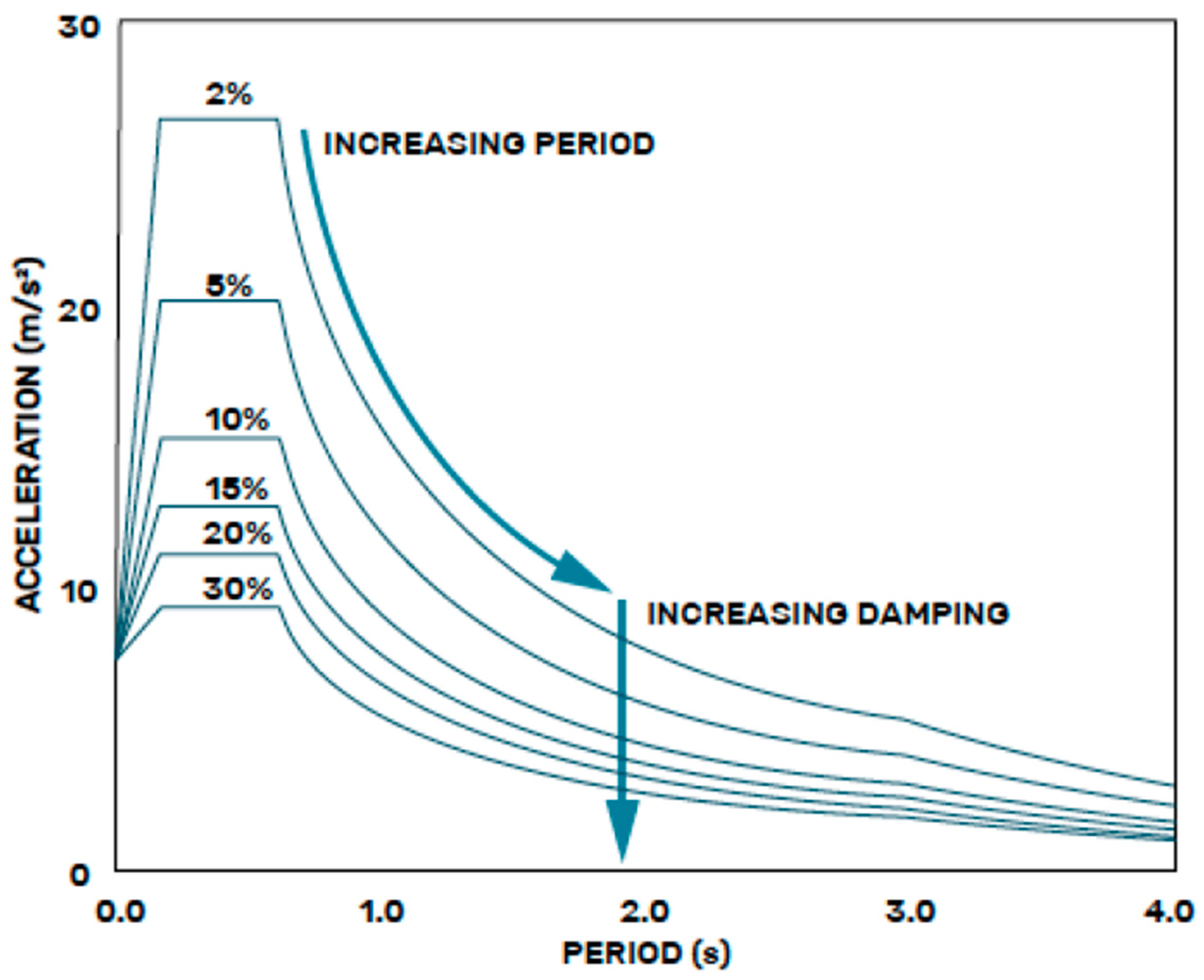
- Energy dissipation and improved damping: seismic isolation systems not only provide flexibility but also enhance energy dissipation, which is crucial for mitigating seismic forces. Some isolation devices exhibit inherent damping characteristics due to their material properties, while hybrid systems integrate additional damping mechanisms at the isolation interface to further attenuate seismic energy. By increasing damping, these systems help limit displacement demands on isolators and enhance the overall resilience and safety of the structure.
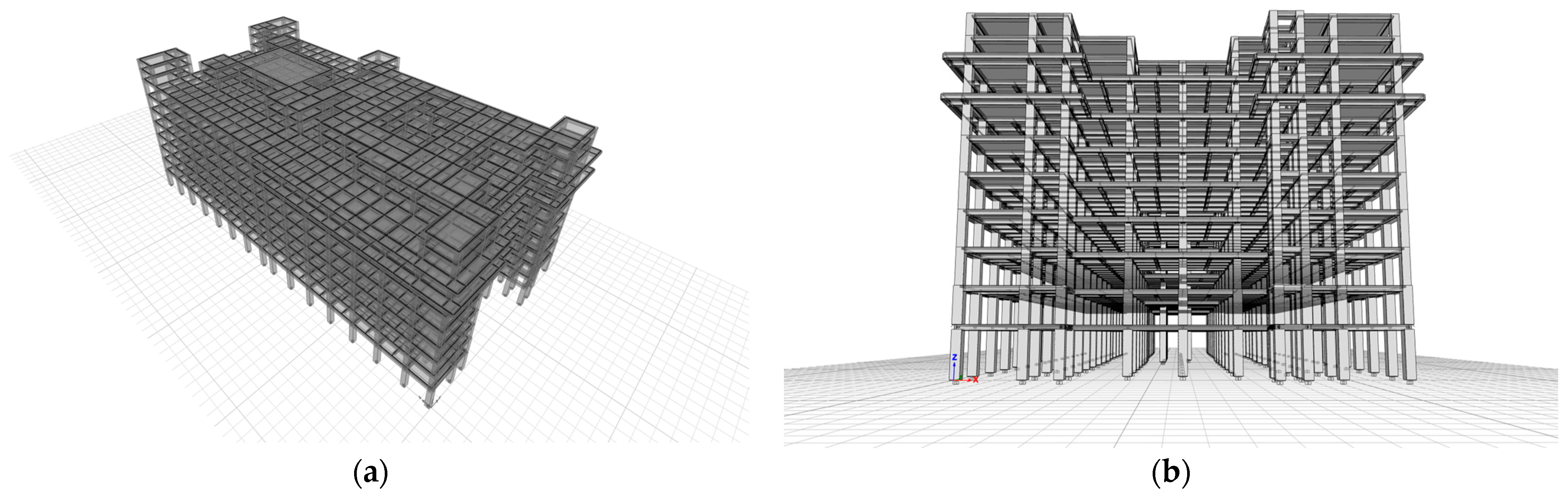
2. Case Study Building and Seismic Action
- represents the effective peak ground acceleration at the base of the structure, expressed as a fraction of gravitational acceleration (). This value is obtained from Table 2.3 of the CSCR-10 [64], based on the seismic zone and the site conditions. The concept of effective peak acceleration originates from ACT 3-06 (1981) [65] and represents the spectral acceleration values within the period range of 0.1 to 0.5 s, where maximum spectral accelerations typically occur. It is determined by averaging the spectral acceleration ordinates at 5% damping and dividing by a factor of 2.5;
- is the importance factor, which is specified in Table 4.1 of CSCR-10 [64] based on the function and occupancy of the structure. This parameter ensures that essential facilities, such as hospitals, are designed to withstand higher seismic demands in accordance with the performance objectives stated in Section 4.1.b of the code [64];
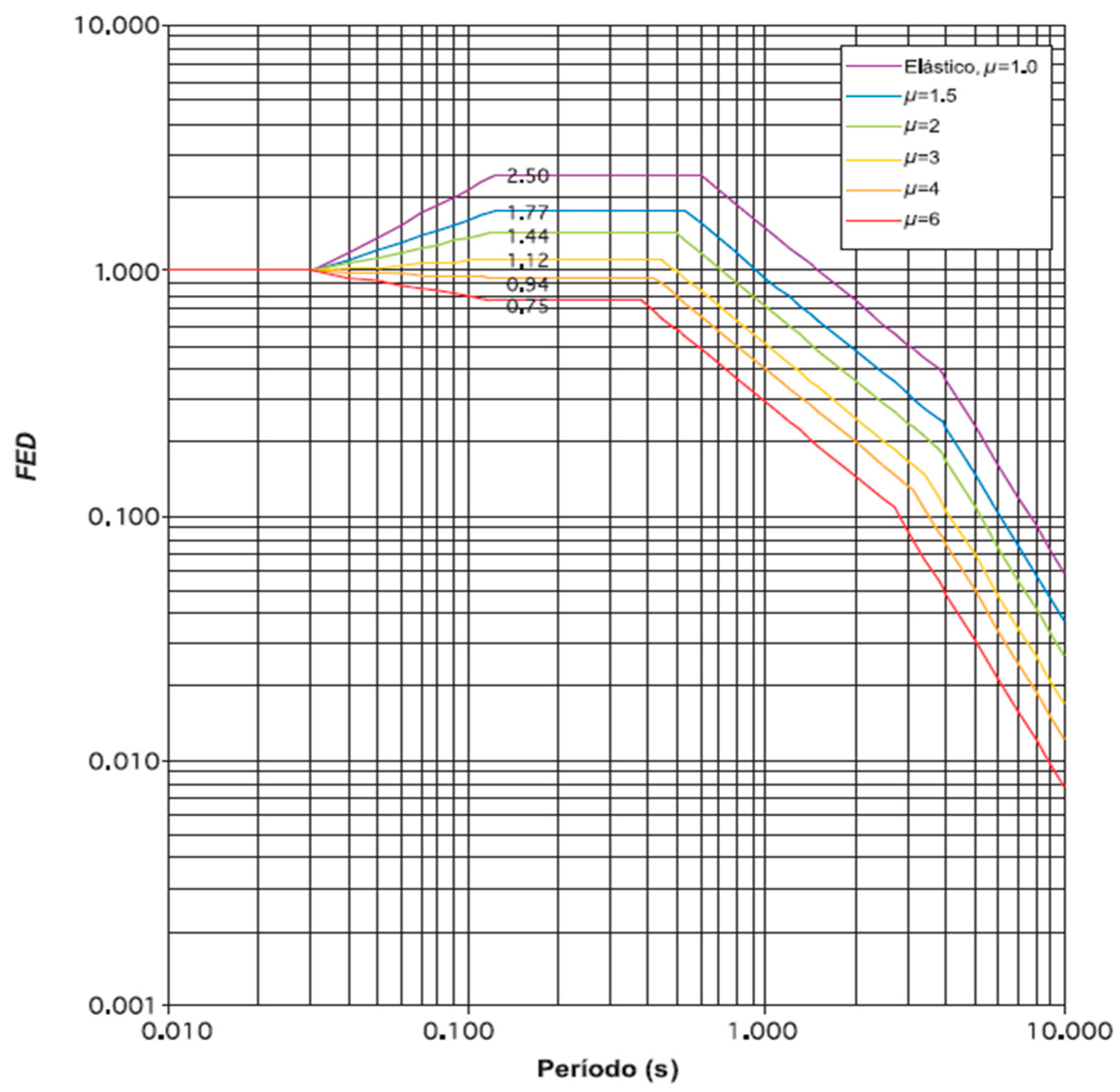
- is the dynamic spectral factor, which defines the shape of the acceleration spectrum based on site conditions, seismic zones, and the assigned global ductility level;
- represents the overstrength factor, which accounts for the difference between the actual and nominal seismic resistance capacity of the structure. According to CSCR-10 [64], the overstrength factor reflects an inherent increase in structural capacity. Instead of directly comparing the actual resistance to the seismic demand, the code evaluates the nominal capacity of the structure against the demand reduced by the factor . This approach justifies the presence of in the denominator of Equation (1).
3. Design Procedures
- European Standard (EN 1998-1—Eurocode 8) [57]
- Equivalent Linear Analysis;
- Simplified Linear Analysis;
- Modal Simplified Linear Analysis;
- Nonlinear Time–History Analysis.
- 2.
- United States Standard (ASCE/SEI 7-22) [58]
- Equivalent Lateral Force Procedure (ELF);
- Dynamic Analysis Procedure;
- Response Spectrum Procedure;
- Response History Procedure (Time–History Analysis).
- The Simplified Linear Analysis method as per Eurocode 8 (EC8) [57].
- The Equivalent Lateral Force (ELF) Procedure as prescribed in ASCE/SEI 7-22 [58].
3.1. European Standard Approach
- Initial displacement :
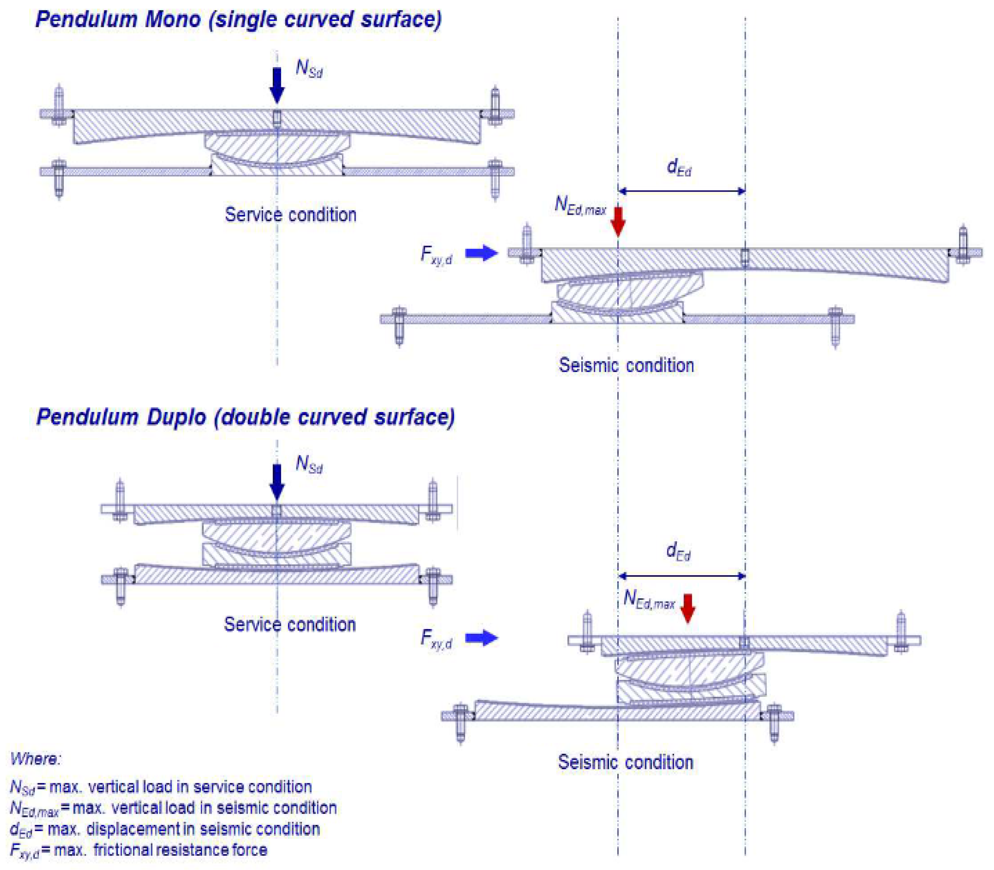
- Equivalent stiffness (), which governs the dynamic response of the isolation system (where is the seismic weight of the structure, equivalent radius ( or ), the initial displacement in Equation (2), and the dynamic coefficient of friction):
- Equivalent stiffness (), representing the effective oscillation period of the isolated structure:
- Equivalent viscous damping (), which accounts for energy dissipation in the system:
- Reduced spectral acceleration, adjusted by the damping factor (), to incorporate the effects of increased damping in the isolation system:
3.2. US Standard Approach
3.3. Bounding Considerations
- Upper Bound Design Properties—UBDP: = 2.5% with = 4%;
- Lower Bound Design Properties—LBDP: = 2.5%, with = 2%.
4. Discussion
- The isolation system must be designed to generate a lateral restoring force such that the period corresponding to its tangent stiffness, at any displacement up to the total design displacement, remains below 6 s:
- The restoring force must be greater than the restoring force at 50% of the design displacement by at least /80, where represents the seismic weight. For a sliding pendulum isolator, the variation in force is given by:where is the design displacement and the lateral stiffness of the frictionless pendulum base isolator. Therefore, by the previous requirement it may be satisfied that:
5. Conclusions
- Validate these findings through full-scale experimental testing of isolated structures designed according to each standard, providing empirical data on re-centering behavior and displacement demands;
- Investigate the implications of different damping models on seismic response, particularly in highly damped systems where standard assumptions may no longer be valid;
- Extend the comparison to include other seismic isolation technologies, such as hybrid isolators and nonlinear time–history analysis approaches, to evaluate their impact on seismic performance predictions.
Author Contributions
Funding
Institutional Review Board Statement
Informed Consent Statement
Data Availability Statement
Conflicts of Interest
Abbreviations
| FPI | Friction Pendulum Isolator |
| SFP | Single Friction Pendulum |
| DFP | Double Friction Pendulum |
| ELA | Equivalent Linear Analysis |
| ELF | Equivalent Lateral Force |
| NLTHA | Nonlinear Time History Analysis |
| EC8 | Eurocode 8 (EN 1998-1) |
| EN | European Norm |
| ASCE | American Society of Civil Engineers |
| AASHTO | American Association of State Highway and Transportation Officials |
| CSCR-10 | Costa Rican Seismic Code (2010) |
| PGA | Peak Ground Acceleration |
| UBDP | Upper Bound Design Properties |
| LBDP | Lower Bound Design Properties |
| DCR | Demand-to-Capacity Ratio |
References
- Feng, D.; Liu, W.; Masuda, K.; Wang, S.; Huan, S. A comparative study of seismic isolation codes worldwide, part 1 Design Spectrum. In Proceedings of the First European Conference on Earthquake Engineering and Seismology, Geneva, Switzerland, 3–8 September 2006. [Google Scholar]
- Nguyen, T.D.; Phung, B.T.; Nguyen, X.D. Comparative Analysis Between the Bridge Standards of USA, EU, Canada, and Vietnam in the Preliminary Design of Seismic Base Isolation. Lect. Notes Civ. Eng. 2024, 482, 253–261. [Google Scholar]
- Aviram, A.; Trifunovic, M.; Zayas, V.; Mokha, A.; Low, S. Recommended Design Criteria and Implementation Strategies for Seismic Isolation. In Proceedings of the IABSE Congress 2024: Beyond Structural Engineering in a Changing World, San Jose, CA, USA, 25 September 2024. [Google Scholar]
- Sivasubramanian, P.; Manimaran, M.; Vijay, U.P. Implementation of Base-Isolation Technique in the Design of Mega Hospital Building. Lect. Notes Civ. Eng. 2024, 440, 299–313. [Google Scholar]
- Ademović, N.; Farsangi, E.N. Review of Novel Seismic Energy Dissipating Techniques Toward Resilient Construction. In Automation in Construction toward Resilience: Robotics, Smart Materials, and Intelligent Systems, 1st ed.; Noroozinejad, E.F., Noori, M., Yang, T., Lourenço, P.B., Gardoni, P., Takewaki, I., Chatzi, E., Li, S., Eds.; CRC Press: Boca Raton, FL, USA, 2023; Volume 1, pp. 551–567. [Google Scholar]
- Ozer, E.; Inel, M.; Cayci, B.T. Seismic Performance Comparison of Fixed and Base-Isolated Models. Iran. J. Sci. Technol.—Trans. Civ. Eng. 2023, 47, 1007–1023. [Google Scholar] [CrossRef]
- Calvi, G.M.; Calvi, P.M.; Moratti, M. Seismic isolation of buildings using devices based on sliding between surfaces with variable friction coefficient. Innov. Infrastruct. Solut. 2017, 2, 39. [Google Scholar] [CrossRef]
- Fagà, E.; Ceresa, P.; Nascimbene, R.; Moratti, M.; Pavese, A. Modelling curved surface sliding bearings with bilinear constitutive law: Effects on the response of seismically isolated buildings. Mater. Struct./Mater. Constr. 2016, 49, 2179–2196. [Google Scholar] [CrossRef]
- Furinghetti, M.; Mansour, S.; Marra, M.; Silvestri, S.; Lanese, I.; Weber, F.; Pavese, A. Shaking table tests of a full-scale base-isolated flat-bottom steel silo equipped with curved surface slider bearings. Soil Dyn. Earthq. Eng. 2024, 176, 108321. [Google Scholar] [CrossRef]
- Furinghetti, M.; Lanese, I.; Pavese, A. Experimental Hybrid Simulation of Severe Aftershocks Chains on Buildings Equipped with Curved Surface Slider Devices. Buildings 2022, 12, 1255. [Google Scholar] [CrossRef]
- Furinghetti, M.; Pavese, A. Experimental Validation of Fast Design Rules for Curved Surface Slider Devices through the Hybrid Simulation Technique. Procedia Struct. Integr. 2022, 44, 1490–1497. [Google Scholar] [CrossRef]
- Asher, J.W.; Hoskere, S.N.; Ewing, R.D.; Mayes, R.L.; Button, M.R.; Van Volkinburg, D.R. Performance of seismically isolated structures in the 1994 Northridge and 1995 Kobe earthquakes. In Proceedings of the 1997 15th Structures Congress, Portland, OR, USA, 13 April 1997. [Google Scholar]
- Kitagawa, Y.; Midorikawa, M. Seismic isolation and passive response-control buildings in Japan. Smart Mater. Struct. 1998, 7, 581–587. [Google Scholar] [CrossRef]
- Aloisio, A.; Rosso, M.M.; De Leo, A.M.; Fragiacomo, M.; Basi, M. Damage classification after the 2009 L’Aquila earthquake using multinomial logistic regression and neural networks. Int. J. Disaster Risk Reduct. 2023, 961, 103959. [Google Scholar] [CrossRef]
- Di Michele, F.; Stagnini, E.; Pera, D.; Rubino, B.; Aloisio, R.; Askan, A.; Marcati, P. Comparison of machine learning tools for damage classification: The case of L’Aquila 2009 earthquake. Nat. Hazards 2023, 116, 3521–3546. [Google Scholar] [CrossRef]
- Nascimbene, R. Investigation of seismic damage to existing buildings by using remotely observed images. Eng. Fail. Anal. 2024, 161, 108282. [Google Scholar] [CrossRef]
- Tatangelo, M.; Audisio, L.; D’Amato, M.; Gigliotti, R. Seismic risk analysis on masonry buildings damaged by L’Aquila 2009 and Emilia 2012 earthquakes. In Proceedings of the 19th ANIDIS Conference, Seismic Engineering, Turin, Italy, 11 September 2022. [Google Scholar]
- Longobardi, G.; Milani, G.; Formisano, A. Seismic Vulnerability Assessment of Churches Affected by the 2012 Emilia—Romagna Earthquake: Comparison among Different Approaches. In Proceedings of the 2024 IEEE International Workshop on Metrology for Living Environment, Chania, Greece, 12 June 2024. [Google Scholar]
- Acito, M.; Buzzetti, M.; Chesi, C.; Magrinelli, E.; Milani, G. Failures and damages of historical masonry structures induced by 2012 northern and 2016–17 central Italy seismic sequences: Critical issues and new perspectives towards seismic prevention. Eng. Fail. Anal. 2023, 149, 107257. [Google Scholar] [CrossRef]
- Singh, S.K.; Pimprikar, S.D.; Bansal, B.K.; Pacheco, J.F.; Dattatrayam, R.S.; Suresh, G. An analysis of the Mw 4.7 Jabalpur, India, earthquake of 16 October 2000: Toward ground-motion estimation in the region from future events. Bull. Seismol. Soc. Am. 2007, 97, 1475–1485. [Google Scholar] [CrossRef]
- Gupta, H.K.; Chadha, R.K.; Rao, M.N.; Narayana, B.L.; Mandal, P.; Ravi, K.M.; Kumar, K. The Jabalpur earthquake of May 22, 1997. J. Geol. Soc. India 1997, 50, 85–91. [Google Scholar] [CrossRef]
- Rai, D. Seismic retrofitting of R/C shaft support of elevated tanks. Earthq. Spectra 2002, 18, 745–760. [Google Scholar] [CrossRef]
- Jagadish, K.S.; Raghunath, S.; Nanjunda, K.S. Behaviour of masonry structures during the Bhuj earthquake of January 2001. In Proceedings of the Indian Academy of Sciences, Earth and Planetary Sciences, Bombay, India, 12 September 2003; Volume 112, Issue 3. pp. 431–440. [Google Scholar]
- Rai, D. Performance of elevated tanks in Mw 7.7 Bhuj earthquake of January 26th, 2001. In Proceedings of the Indian Academy of Sciences, Earth and Planetary Sciences, Bombay, India, 12 September 2003; Volume 112, Issue 3. pp. 421–429. [Google Scholar]
- Hough, S.E.; Martin, S.; Bilham, R.; Atkinson, G.M. A media-based assessment of damage and ground motions from the January 26th, 2001 M 7.6 Bhuj, India earthquake. In Proceedings of the Indian Academy of Sciences, Earth and Planetary Sciences, Bombay, India, 12 September 2003; Volume 112, Issue 3. pp. 353–373. [Google Scholar]
- Bradley, B.A.; Wotherspoon, L.M.; Kaiser, A.E.; Cox, B.R.; Jeong, S. Influence of site effects on observed ground motions in the Wellington region from the Mw 7.8 Kaikōura, New Zealand, earthquake. Bull. Seismol. Soc. Am. 2018, 108, 1722–1735. [Google Scholar] [CrossRef]
- Yazdanian, M.; Ingham, J.M.; Kahanek, C.; Dizhur, D. Damage to legged wine storage tanks during the 2013 and 2016 New Zealand earthquakes. J. Constr. Steel Res. 2020, 172, 106226. [Google Scholar] [CrossRef]
- Crowley, K.; Elliott, J.R. Earthquake disasters and resilience in the global north: Lessons from New Zealand and Japan. Geogr. J. 2012, 178, 208–215. [Google Scholar] [CrossRef]
- Kocakaplan Sezgin, S.; Sakcalı, G.B.; Özen, S.; Yıldırım, E.; Avcı, E.; Bayhan, B.; Çağlar, N. Reconnaissance report on damage caused by the February 6, 2023, Kahramanmaraş Earthquakes in reinforced-concrete structures. J. Build. Eng. 2024, 89, 109200. [Google Scholar] [CrossRef]
- Işık, E.; Avcil, F.; İzol, R.; Büyüksaraç, A.; Bilgin, H.; Harirchian, E.; Arkan, E. Field Reconnaissance and Earthquake Vulnerability of the RC Buildings in Adıyaman during 2023 Türkiye Earthquakes. Appl. Sci. 2024, 14, 2860. [Google Scholar] [CrossRef]
- Marinković, M.; Baballëku, M.; Isufi, B.; Blagojević, N.; Milićević, I.; Brzev, S. Performance of RC cast-in-place buildings during the November 26, 2019 Albania earthquake. Bull. Earthq. Eng. 2022, 20, 5427–5480. [Google Scholar] [CrossRef]
- Nascimbene, R.; Brunesi, E.; Sisti, A. Expeditious numerical capacity assessment in precast structures via inelastic performance-based spectra. Heliyon 2024, 10, e39729. [Google Scholar] [CrossRef] [PubMed]
- Magliulo, G.; Ercolino, M.; Petrone, C.; Coppola, O.; Manfredi, G. The Emilia earthquake: Seismic performance of precast reinforced concrete buildings. Earthq. Spectra 2014, 30, 891–912. [Google Scholar] [CrossRef]
- Furtado, A.; Rodrigues, H.; Arêde, A.; Varum, H. A review of the performance of infilled rc structures in recent earthquakes. Appl. Sci. 2021, 11, 5889. [Google Scholar] [CrossRef]
- Pavese, A.; Lanese, I.; Nascimbene, R. Seismic Vulnerability Assessment of an Infilled Reinforced Concrete Frame Structure Designed for Gravity Loads. J. Earthq. Eng. 2017, 21, 267–289. [Google Scholar] [CrossRef]
- Brunesi, E.; Nascimbene, R.; Pavese, A. Mechanical model for seismic response assessment of lightly reinforced concrete walls. Earthq. Struct. 2016, 11, 461–481. [Google Scholar] [CrossRef]
- Georgiev, T. Field Observations and Assessment of Performance Level of Steel Structures After the Kahramanmaras Earthquake Sequence of 2023. In Proceedings of the 11th International Conference on Behaviour of Steel Structures in Seismic Areas, STESSA 2024, Salerno, Italy, 10 July 2024. [Google Scholar]
- Iyama, J.; Matsuo, S.; Kishiki, S.; Ishida, T.; Azuma, K.; Kido, M.; Iwashita, T.; Sawada, K.; Yamada, S.; Seike, T. Outline of reconnaissance of damaged steel school buildings due to the 2016 Kumamoto earthquake. AIJ J. Technol. Des. 2018, 24, 183–188. [Google Scholar] [CrossRef]
- Matsumoto, Y.; Koyama, T.; Yamada, S.; Iyama, J.; Kishiki, S.; Shimada, Y. Seismic damage to roof and non-structural components in steel school buildings due to the 2011 tohoku earthquake. AIJ J. Technol. Des. 2014, 20, 121–126. [Google Scholar] [CrossRef]
- Filiatrault, A.; Tremblay, R.; Wanitkorkul, A. Performance evaluation of passive damping systems for the seismic retrofit of steel moment-resisting frames subjected to near-field ground motions. Earthq. Spectra 2001, 17, 427–456. [Google Scholar] [CrossRef]
- Nagarajaiah, S.; Reinhorn, A.M.; Constantinou, M.C. Nonlinear Dynamic Analysis of Three-Dimensional Base Isolated Structures (3D-Basis); National Center for Earthquake Engineering Research: Buffalo, NY, USA, 1989. [Google Scholar]
- Yaacoub, E.; Nascimbene, R.; Furinghetti, M.; Pavese, A. Evaluating Seismic Isolation Design: Simplified Linear Methods vs Nonlinear Time History Analysis. Designs 2025. to be published. [Google Scholar] [CrossRef]
- Christopoulos, C.; Filatrault, A. Principles of Passive Supplemental Damping and Seismic Isolation, 1st ed.; IUSS Press: Pavia, Italy, 2006. [Google Scholar]
- Grant, D. Seismic isolation and supplemental damping. In Seismic Design of Buildings, 2nd ed.; United Kingdom CRC Press, Ed.; Routledge Publisher: London, UK, 2016. [Google Scholar]
- Gabbianelli, G.; Milanesi, R.; Gandelli, E.; Dubini, P.; Nascimbene, R. Seismic vulnerability assessment of steel storage tanks protected through sliding isolators. Earthq. Eng. Struct. Dyn. 2023, 52, 2597–2618. [Google Scholar] [CrossRef]
- Khalil, M.; Ruggieri, S.; Tateo, V.; Nascimbene, R.; Uva, G. A numerical procedure to estimate seismic fragility of cylindrical ground-supported steel silos containing granular-like material. Bull. Earthq. Eng. 2023, 21, 5915–5947. [Google Scholar] [CrossRef]
- Kazantzi, A.K.; Karaferis, N.D.; Melissianos, V.E.; Vamvatsikos, D. Acceleration-sensitive ancillary elements in industrial facilities: Alternative seismic design approaches in the new Eurocode. Bull. Earthq. Eng. 2024, 22, 109–132. [Google Scholar] [CrossRef]
- Gandelli, E.; Taras, A.; Distl, J.; Quaglini, V. Seismic Retrofit of Hospitals by Means of Hysteretic Braces: Influence on Acceleration-Sensitive Non-structural Components. Front. Built Environ. 2019, 5, 100. [Google Scholar] [CrossRef]
- Kazantzi, A.K.; Vamvatsikos, D.; Miranda, E. Evaluation of Seismic Acceleration Demands on Building Nonstructural Elements. J. Struct. Eng. 2020, 146, 04020118. [Google Scholar] [CrossRef]
- Zito, M.; Nascimbene, R.; Dubini, P.; D’Angela, D.; Magliulo, G. Experimental Seismic Assessment of Nonstructural Elements: Testing Protocols and Novel Perspectives. Buildings 2022, 12, 1871. [Google Scholar] [CrossRef]
- Merino, R.J.; Perrone, D.; Nascimbene, R.; Filiatrault, A. Performance-based seismic classification of acceleration-sensitive non-structural elements. Earthq. Eng. Struct. Dyn. 2023, 52, 4222–4244. [Google Scholar] [CrossRef]
- Merino, R.J.; Rodriguez, D.; Peloso, S.; Brunesi, E.; Perrone, D.; Filiatrault, A.; Nascimbene, R. Experimentally Calibrated Numerical Modeling for Performance-Based Seismic Design of Low-Frequency Rocking Electrical Cabinets. J. Earthq. Eng. 2024. [Google Scholar] [CrossRef]
- Cho, S.G.; Kim, D.; Chaudhary, S. A simplified model for nonlinear seismic response analysis of equipment cabinets in nuclear power plants. Nucl. Eng. Des. 2011, 241, 2750–2757. [Google Scholar] [CrossRef]
- Constantinou, M.C.; Tsopelas, P.; Kasalanati, A.; Wolff, E.D. Property Modification Factors for Seismic Isolation Bearings; National Center for Earthquake Engineering Research: Buffalo, NY, USA, 1999. [Google Scholar]
- EN 15129; Anti-Seismic Devices. European Committee for Standardization: Brussels, Belgium, 2018.
- EN 1337-2; Structural Bearings, Part 2, Sliding Elements. European Committee for Standardization: Brussels, Belgium, 2004.
- EN 1998-1; Eurocode 8: Design of Structures for Earthquake Resistance—Part 1: General Rules, Seismic Actions and Rules for Buildings. European Committee for Standardization: Brussels, Belgium, 2004.
- ASCE 7-22; Minimum Design Loads and Associated Criteria for Buildings and Other Structures (ASCE/SEI 7-22). American Society of Civil Engineers: Reston, VA, USA, 2022.
- AASHTO-GSID: Guide Specifications for Seismic Isolation Design; American Association of State Highway and Transportation Officials: Washington, DC, USA, 2014.
- ETABS Software, Version 21; Computer and Structures, Inc.: Berkeley, CA, USA, 2024.
- Arroyo-Solórzano, M.; Quesada-Román, A. Morphotectonic Regions of Costa Rica: A Review and Updated Classification. In World Geomorphological Landscapes; Piotr, M., Ed.; Springer International Publishing: Heidelberg, Germany, 2024; Volume F3501, pp. 1–35. [Google Scholar]
- Montero, P.W. Historical seismology of Costa Rica 1638–1910. Geofis. Int. 1989, 28, 531–559. [Google Scholar] [CrossRef]
- Benito, M.B.; Lindholm, C.; Camacho, E.; Climent, A.; Marroquin, G.; Molina, E.; Rojas, W.; Escobar, J.J.; Talavera, E.; Alvarado, G.E.; et al. A New Evaluation of Seismic Hazard for the Central America Region. Bull. Seismol. Soc. Am. 2012, 102, 504–523. [Google Scholar] [CrossRef]
- CSCR-10 Rev. 2014—CFIA. (2010). Costa Rican Seismic Code—Revision 2014; Editorial Tecnólogica de Costa Rica: San José, CA, USA, 2014.
- ACT 3-06; Review and Refinement of ATC 3-06 Tentative Seismic Provisions. Building Seismic Safety Council: Washington, DC, USA, 1981.
- Beirami, A.; Ahari, G.Z.; Barghian, M. Base isolation systems-a state of the art review according to their mechanism. J. Rehabil. Civ. Eng. 2020, 8, 37–61. [Google Scholar]
- Skinner, R.I.; Robinson, W.H.; McVerry, G.H. An Introduction to Seismic Isolation, 1st ed.; Wiley: Hoboken, NJ, USA, 1993. [Google Scholar]
- Medeot, R. Re-Centering Capability Evaluation of Seismic Isolation Systems Based on Energy Concepts. In Proceedings of the 13th World Conference on Earthquake Engineering, Vancouver, BC, Canada, 1 August 2004. Paper No. 3106. [Google Scholar]


| Parameter | Assumed Value |
|---|---|
| Effective peak ground acceleration | 0.36 |
| Importance factor | 1.25 |
| Dynamic spectral factor | Table E.7 in CSCR-10 [64] |
| Overstrength factor | 1.0 |
| Parameter | Eurocode 8 | ASCE/SEI 7-22 | [%] |
|---|---|---|---|
| Displacement [mm] | 136.62 | 157.23 | 15.35 |
| Equivalent stiffness [kN/mm] | 323.60 | 305.39 | 5.63 |
| Equivalent period [sec] | 3.05 | 3.14 | 2.95 |
| Equivalent viscous damping [%] | 26.94 | 24.75 | 8.13 |
| Damping factor | 0.56 | 1.59 | 12.30 |
| Acceleration | 0.059 | 0.064 | 8.62 |
| Maximum displacement [mm] | 136.32 | 157.23 | 15.35 |
| Maximum horizontal force [kN] | 44,113.84 | 48,017.53 | 8.85 |
| Parameter | Eurocode 8 | UBDP | LBDP |
|---|---|---|---|
| Displacement [mm] | 136.62 | 113.72 | 163.11 |
| Equivalent stiffness [kN/mm] | 323.60 | 449.3 | 278.22 |
| Equivalent period [sec] | 3.05 | 2.59 | 3.29 |
| Equivalent viscous damping [%] | 26.94 | 37.31 | 20.95 |
| Damping factor | 0.56 | 0.55 | 0.62 |
| Acceleration | 0.059 | 0.068 | 0.061 |
| Maximum displacement [mm] | 136.32 | 113.72 | 163.11 |
| Maximum horizontal force [kN] | 44,113.84 | 51,094.24 | 45,380.43 |
Disclaimer/Publisher’s Note: The statements, opinions and data contained in all publications are solely those of the individual author(s) and contributor(s) and not of MDPI and/or the editor(s). MDPI and/or the editor(s) disclaim responsibility for any injury to people or property resulting from any ideas, methods, instructions or products referred to in the content. |
© 2025 by the authors. Licensee MDPI, Basel, Switzerland. This article is an open access article distributed under the terms and conditions of the Creative Commons Attribution (CC BY) license (https://creativecommons.org/licenses/by/4.0/).
Share and Cite
Vargas, D.; Nascimbene, R.; Marioni, A.; Banfi, M. A Comparative Analysis of International Standards on Curved Surface Isolators for Buildings. Appl. Sci. 2025, 15, 4254. https://doi.org/10.3390/app15084254
Vargas D, Nascimbene R, Marioni A, Banfi M. A Comparative Analysis of International Standards on Curved Surface Isolators for Buildings. Applied Sciences. 2025; 15(8):4254. https://doi.org/10.3390/app15084254
Chicago/Turabian StyleVargas, David, Roberto Nascimbene, Agostino Marioni, and Marco Banfi. 2025. "A Comparative Analysis of International Standards on Curved Surface Isolators for Buildings" Applied Sciences 15, no. 8: 4254. https://doi.org/10.3390/app15084254
APA StyleVargas, D., Nascimbene, R., Marioni, A., & Banfi, M. (2025). A Comparative Analysis of International Standards on Curved Surface Isolators for Buildings. Applied Sciences, 15(8), 4254. https://doi.org/10.3390/app15084254