Review

The Evolution and Development Trends of LNG Loading and Unloading Arms

School of Mechanical Engineering, Jiangsu Ocean University, Lianyungang 222000, China
*
Author to whom correspondence should be addressed.
Appl. Sci. 2025, 15(8), 4316; https://doi.org/10.3390/app15084316
Submission received: 7 March 2025 / Revised: 9 April 2025 / Accepted: 10 April 2025 / Published: 14 April 2025

Abstract

:
In recent years, the rapid growth in demand for liquefied natural gas (LNG) has brought significant challenges and opportunities to LNG storage and transportation technologies. As critical equipment for LNG loading operations, marine and land-based LNG loading and unloading arms play a vital role in improving LNG storage and transportation efficiency and ensuring safety performance. By extensively collecting relevant domestic and international literature, technical standards, and engineering cases, systematically reviewing and analyzing existing achievements, and engaging with technical personnel from related enterprises, the current development status of marine and land-based LNG loading and unloading arms is introduced from multiple perspectives, including overall structure, sealing technology, safety protection devices, and intelligent and automated development. This paper highlights trajectory planning and image processing involved in the automatic docking technology. Marine loading/unloading arms need to operate in high-humidity, high-corrosion, and even extreme weather conditions. In the future, they should further enhance stability in marine high-corrosion environments and improve anti-overturning capability under extreme conditions by simplifying mechanical structures, developing new balancing systems, and using low-temperature-resistant alloy materials. Land-based loading and unloading arms focus on multi-vehicle parallel operations, improving operational efficiency through simplified mechanical structures, integrated intelligent positioning systems, and adaptive control algorithms.

1. Introduction

At present, economic development, population growth, industrialization, and urbanization are important reasons for the rapid growth in global energy consumption. The world population will increase by 22% in 2040. During the period from 2000 to 2013, worldwide energy consumption was raised nearly 2.4% per annum [1]. From 2012 to 2035, the global energy consumption is expected to increase by 41%. So far, oil remains the main source of global energy consumption. The combustion of oil and coal generates large amounts of sulfides, nitrogen oxides, and carbon dioxide, which have a serious impact on the global ecology and climate change. In parallel, renewable energy represented by solar and wind power is accelerating its displacement of conventional energy sources. For example, solar photovoltaic technology enables the widespread application of solar energy due to its advantages such as no toxic emissions, no noise, and ease of maintenance [2]. However, solar energy storage and utilization technologies remain immature, and solar energy utilization faces unreliability risks due to natural constraints. Thus, natural gas is currently considered one of the cleanest energy sources.
Liquefied natural gas (LNG for short), as a clean, environmentally friendly and high-quality energy source, is an important raw material for modern industry and plays an important role in the third energy transition [3]. In 2023, China imported 165.56 × 10⁸ m3 of LNG, an increase of 14.76 × 10⁸ m3 compared with 2022 [4]. China surpassed countries such as Japan to become the world’s largest importer of liquefied natural gas. In the past two decades, the application technology of LNG has developed unprecedentedly. An LNG industry involving various links from liquefaction, storage, transportation, to end-use, as well as the manufacturing of supporting equipment, has been gradually established, which has become an important feature of the development of the LNG industry [5].
At present, the main transportation methods of natural gas globally are pipeline transportation and liquefied natural gas (LNG) transportation [6]. Pipeline transportation is suitable for long-distance and large-capacity transportation demands, while LNG transportation is applicable to ocean-going transportation [7]. It can break through environmental barriers, is more flexible and convenient, and better conforms to the trend of globalization. LNG transportation is the key to future development. The transportation methods of LNG include marine transportation and land transportation. Marine transportation uses LNG carriers to complete the long-distance transportation and storage of LNG [8], and land transportation uses LNG tank trucks to deliver LNG from large-scale receiving terminals or production points to specific consumption points.
Whether it is maritime transportation or land transportation, the loading and unloading process of LNG is required, and this process requires a key piece of equipment, namely the LNG loading and unloading arm. With the rapid development of the application fields of LNG and the growth of LNG demand, higher requirements are put forward for the performance and technical level of LNG loading and unloading equipment, and the LNG loading and unloading equipment industry will also develop rapidly. This article conducts research on aspects such as the origin, development history, structural characteristics, principles and structures of key components, and key technologies of the loading and unloading arm. From dimensions such as structural lightweighting, intelligent control, and high-performance materials, it proposes the technical routes for future research. It not only systematically combs the development context of LNG loading and unloading arm technology but also conducts a quantitative analysis of the optimization of key technologies and indicators, providing experimental parameters and comparison benchmarks for subsequent research. The shift from “manual operation” loading and unloading to “autonomous intelligent” loading and unloading indicates the direction of the technical route for intelligent upgrading and reliability enhancement, which has positive significance for promoting the technical level of LNG loading and unloading equipment.
This paper systematically reviews the technological development history and future trends of liquefied natural gas (LNG) loading and unloading arms. The paper is divided into four parts: The first part is the introduction, which elaborates on the background of the LNG industry and the importance of loading and unloading arms. The second part analyzes in detail the key technologies of marine LNG loading and unloading arms, including the overall structure, swivel joint sealing, emergency disconnect devices, and intelligent development. The third part explores the structural optimization, sealing technology innovation, and automation upgrade of land-based LNG loading and unloading arms. The fourth part summarizes the current technological challenges and proposes the core directions for future development. By integrating domestic and international technical standards, engineering cases, and the latest research results, this paper aims to provide theoretical support and practical references for the optimization and innovation of LNG loading and unloading equipment.

2. Development of Marine LNG Loading and Unloading Arms

In the mid-19th century, Ludwig designed the world’s first flexible loading and unloading arm, which could effectively prevent oil and gas leakage [9]. In 1956, FMC Corporation manufactured the world’s first marine fluid loading and unloading equipment, and in the 1970s, it successfully developed the world’s first 600 mm-caliber fluid loading and unloading arm. Internationally, there are mainly three structures of fluid loading and unloading equipment, namely the self-supporting mechanism of FMC Corporation, the independent supporting structure of SVT in Germany, and the new four-bar linkage transmission mechanism of Kanon in the Netherlands [10]. The Dutch company Kanon combined these three structures to develop a new type of fluid loading and unloading arm with a self-supporting and independent supporting mechanism, which can greatly improve the actual working performance of the fluid loading and unloading arm. In addition, the British company Woodfield has conducted in-depth research on special loading and unloading arms. Based on the traditional fluid loading and unloading arms, it has developed a new type of special fluid loading and unloading arm with low-temperature resistance and corrosion resistance, which can transport corrosive products at a low temperature of minus 150 degrees. The development history of LNG loading and unloading arms is shown in Figure 1.
The marine LNG loading and unloading arm is an important facility installed at the dock for unloading LNG from LNG carriers [11]. When an LNG carrier arrives at the receiving terminal, LNG is transported to the terminal storage tanks through a series of devices such as liquid-phase loading and unloading arms and unloading pipelines [12]. Internationally, there are only a handful of manufacturers that can independently produce marine LNG loading and unloading arms. Typical structures of marine LNG loading and unloading arms include the products of FMC Technologies, Connex SVT in Germany, and Niigata in Japan. For example, the ARCTIC-type LNG loading and unloading arm produced by SVT in Germany can complete the loading task in an environment of −196 °C and 45 bar.

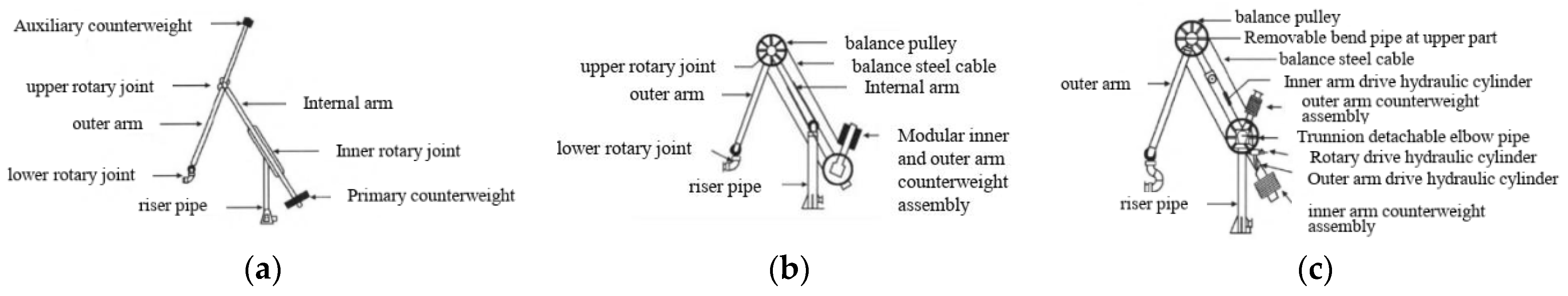
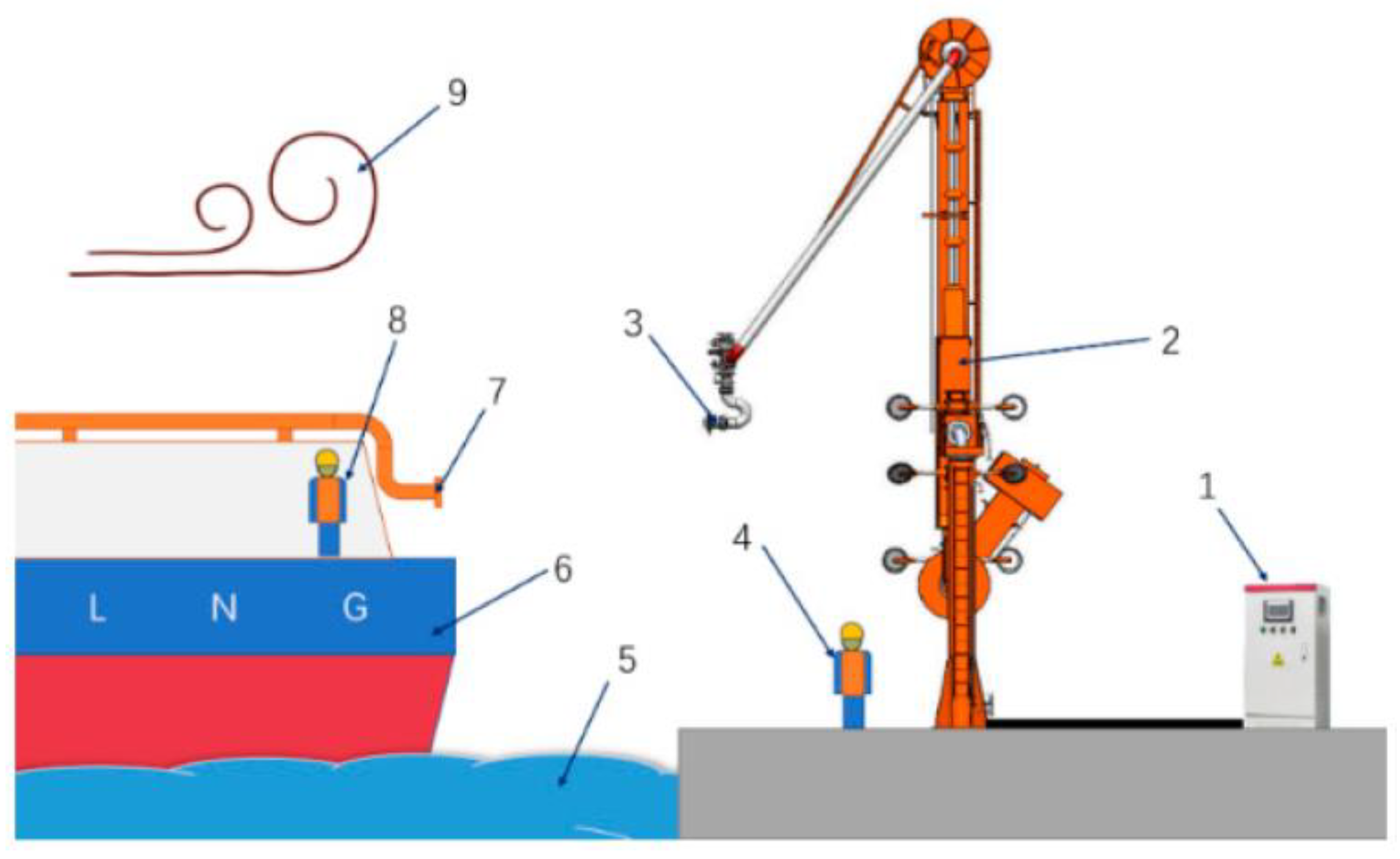
2.1. Overall Structure of the Marine Loading Arm

The marine LNG loading arm consists of five major components: riser pipe, trunnion box, inner arm, outer arm, and counterweight [13]. It is a loading and unloading device for tankers to load and unload liquid media. Each loading system of an LNG receiving terminal is composed of three liquid-phase arms and one gas-phase arm. The sizes of the loading and unloading arms include 12-inch, 16-inch, 20-inch, etc. arms. Currently, the 16-inch loading and unloading arm is the most widely used [14]. The marine loading and unloading arm in working condition is shown in Figure 2.
There are three types of balance methods for marine loading and unloading arms: the full-balance type, rotary-balance type, and double-balance type. The full-balance-type loading and unloading arm adopts a self-supporting structure; the case is depicted in Figure 3a. The internal and external loads of the loading and unloading arm as well as all bending moments are borne by the rotary joint with a hard raceway, reducing the dependence on external support. The rotary-balance-type loading and unloading arm adopts an independent supporting structure; the case is depicted in Figure 3b. The loading pipe is relatively independent of the supporting structure, and the weights of the inner and outer arms are balanced through a single counterweight system. The double-balance-type loading arm balances the inner and outer arms through two independent balance systems; the case is depicted in Figure 3c. It can respond quickly in case of an emergency disconnection of the loading arm and has more advantages in preventing the unbalanced dynamic movement of the loading arm. In addition, there are four commonly used structures for loading and unloading arms: the self-supporting double-counterweight single-tube type, mixed-supporting single-counterweight single-tube type, independent-supporting single-counterweight single-tube type, and independent-supporting single-counterweight double-tube type. The double-tube structure is widely used due to its higher safety and flexibility. Taking the most widely used single-counterweight loading arm as an example, by placing counterweight blocks at specific positions, the weight of the loading arm is distributed reasonably, so that the center of gravity is near the hinge point in the middle section of the inner arm. The counterweight swings synchronously with the outer arm, which can balance the weights of the outer arm and the three-dimensional joint, achieving the self-weight balance of the loading arm [16].
The loading arm has three core components: the cryogenic swivel joint, the emergency release system (ERS), and the quick-connect/disconnect device (QC/DC). The cryogenic swivel joint is used to connect different components of the fluid loading arm, ensuring that the loading arm can rotate freely during the loading process, guaranteeing the stable transmission of the fluid medium and playing a sealing role. The ERS is a protective device used to quickly cut off the connection between the ship and the end of the loading arm in case of emergencies. The QC/DC is installed at the very end of the three-dimensional joint of the loading arm. Its main components include a straight joint pipe, a clamping mechanism, and a driving device, which are used for quick connection with the tanker interface [17]. Currently, the QC/DC has two forms: manual and hydraulic-driven. For example, the Quikcon III quick-connector designed by FMC Corporation adopts a hydraulic drive system. One hydraulic distributor controls five hydraulic fasteners, and these five hydraulic fasteners can complete the fastening work simultaneously when tightening the connecting flange. In case of a failure of the hydraulic or electrical system, the QC/DC should have an automatic protection function to ensure the safe locking with the flange of the LNG carrier.

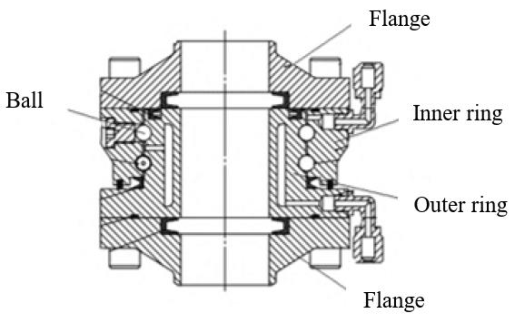
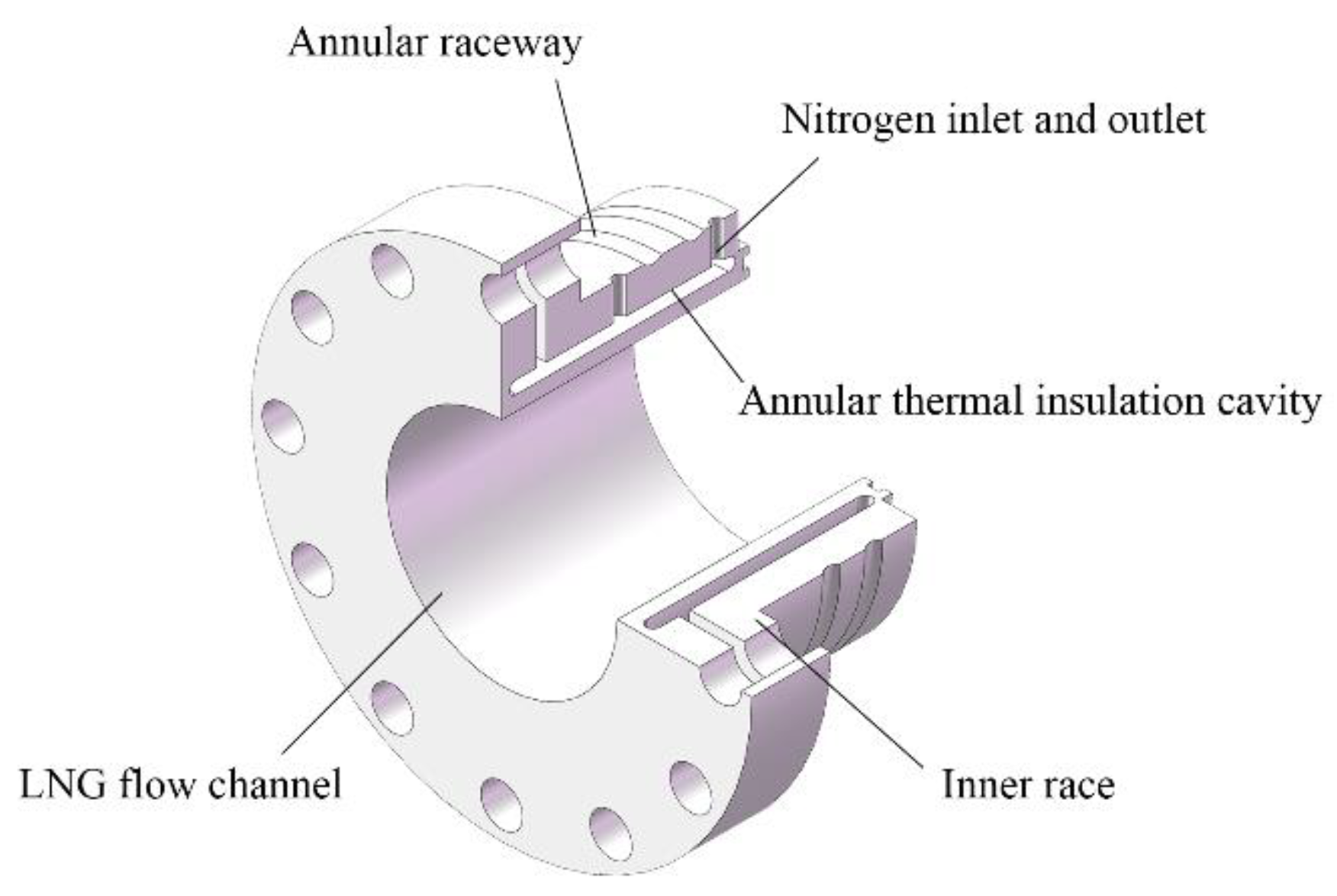
2.1.1. Rotary Joints and Sealing of the Marine Loading Arm

LNG leakage is the main source of danger during the LNG transportation process. Once LNG leaks, it will immediately evaporate into gas and is extremely likely to explode once it encounters a fire source. Moreover, LNG is a cryogenic liquid at −162 °C. Contact with the skin can cause severe frostbite, posing a great threat to the safety of surrounding workers. Whether in the early design stage or the later production and assembly process, preventing the leakage of cryogenic loading and unloading arms is of particular importance [18]. During the production and R&D process, there are many possible causes of leakage, including unqualified welding quality, unqualified flange assembly quality, unreasonable rotary joint design, sub-standard quality of standard parts such as valves, etc. Among them, the rotary joint is a common factor leading to the leakage of cryogenic loading and unloading arms. The cryogenic rotary joint is the “heart” of the LNG loading arm and a key component for the long-term and stable operation of the loading arm [19]. The cryogenic rotary joint consists of rotating parts and sealing parts, including sealing flanges, gaskets, inner races, outer races, balls, etc. [20]. Its typical structure is shown in Figure 4.
The sealing of the rotary joint includes two parts: dynamic sealing and static sealing. The dynamic sealing side is the rotating connection surface, which is mainly used to prevent the medium in the process pipeline from leaking into the ball chamber. During the rotation of the rotary joint, the seal and the sealing surface will produce corresponding friction. The static sealing side is the static connection surface, which is used for the sealing of the process pipeline medium and the isolation sealing of the ball chamber from the outside atmosphere [21]. Pereira et al. [22] conducted a rigorous assessment of the main seal failure in rotary joints using the RCA modeling approach. They found that the residual LNG underwent explosive evaporation after being purged with nitrogen, which subsequently pushed the seal out of its groove.
In addition, the sealing device of the rotary joint in the world mostly adopts a double sealing ring structure. The main seal is mainly responsible for preventing the fluid from leaking between the rotating part and the fixed part of the rotary joint. The secondary seal is used as a backup or auxiliary seal for the main seal, which can play a sealing role when the main seal leaks and ensure the safe operation of the joint. For example, the double-sealed rotary joint of Niigata Company uses low-temperature-resistant stainless steel as the material. The main seal structure is a series arrangement of double polytetrafluoroethylene seals, and the secondary seal chooses a water seal to prevent the ball bearing from being damaged by water or dust from the outside world.
The extremely low-temperature characteristic of LNG will cause the water vapor accumulated in the rotary joint to freeze, thereby damaging the internal raceway. In order to solve this problem, most of the existing rotary joints use the cavity formed between the bushing and the inner ring as the heat insulation cavity of the rotary joint [23]. Although this structural design solves the problem of raceway damage, not only does the structure of the rotary joint become more complex, but the sealing of the heat insulation cavity also becomes a difficult problem. Against this background, Yu [24] and others adopted a double sealing ring structure and provided an annular heat insulation cavity inside the inner ring to reduce the traditional bushing structure; the case is depicted in Figure 5. The active sealing ring is pre-compressed to compensate for the reduced sealing effect of the sealing material due to low-temperature shrinkage and wear. A nitrogen purging system is added to purge the water vapor into the atmosphere through dry nitrogen during the operation of the loading arm, improving the safety of the raceway.

2.1.2. Emergency Disconnection System

The emergency disconnection system (ERS) in the LNG loading arm mainly consists of an emergency release coupler (ERC), an electrical control system, and a hydraulic control system. When a disaster occurs at the loading site or the LNG ship moves out of the specified envelope range, the system will automatically close the valves of the emergency release coupler and safely separate the loading arm from the LNG ship. In addition, the valves on both sides of the emergency release coupler can be closed and separated by manually operating the electrical control system.
In the 1980s, foreign loading arm manufacturers were committed to the research and development of emergency disconnection devices for loading and unloading arms and successfully applied them to loading and unloading arms for petroleum, liquefied natural gas, etc., avoiding major accidents many times. In 1982, the Italian company MIB successfully designed the first emergency disconnection device for LNG loading and unloading arms. The device consists of an emergency disconnection joint and two ball valves. The ball valves are driven to close by an interlocking hydraulic system and can operate stably under ultra-low temperature conditions. The emergency disconnection devices of SVT and FMC both adopt a double-ball-valve interlocking emergency cut-off structure, which are controlled by a single hydraulic cylinder. The valves are closed and the joints are disengaged through a mechanical or hydraulic interlocking system [25]. The emergency disconnection device of the British company KLAW adopts its unique Flip-Flap flap valve technology. Compared with the commonly used spring-lifted valve technology, it has a lighter structure. Even if the device suffers partial fracture, the valve can still be closed smoothly.
At present, the emergency disconnection devices of loading and unloading arms in China’s domestic LNG receiving stations mostly use equipment from companies such as SVT and FMC. Meanwhile, the research on emergency disconnection devices is also in a stage of rapid development. Yu Feng and others proposed a cryogenic emergency disconnection device with superior sealing performance. By setting the upper valve body spool and the lower valve body spool of the self-sealing valve in an opposite-top manner and fixing them with a clamp assembly, the sealing performance of the device after disconnection is effectively ensured. The emergency disconnection device developed by CNOOC Gas and Power Group adopts a mechanical interlock structure, which can complete rapid disconnection and self-locking within five seconds. Chen Peng and others proposed using a worm-gear drive mechanism to drive the opening and closing of the valve. The worm-gear mechanism and the locking device are driven by a hydraulic system to achieve step-by-step control of the valve and the locking mechanism. In view of the problem that the hydraulic cylinder and the four-bar mechanism are easily pulled and damaged when the left and right valve bodies of the emergency disconnection device are separated, Zhang Zhufu and others designed a hydraulic cylinder with an emergency disconnection function, which can simultaneously close the valve of the emergency disconnection device and separate the hydraulic cylinder and the four-bar mechanism. In 2023, Lianyungang Ocean Fluid Loading and Unloading Equipment Co., Ltd. (SOSCO), successfully achieved the complete localization of the cryogenic emergency disconnection device, being able to close the cut-off valve within 5–10 s and complete the separation of the loading arm from the tank ship within 2 s, reaching the international first-class level.
Emergency disconnection devices generally have supporting hydraulic or pneumatic systems to drive their normal operation. Currently, there is a common problem in hydraulic systems, that is, due to leakage, the pressure-holding pressure of the hydraulic system is insufficient, and the hydraulic oil pump is in operation for a long time. When an emergency occurs, the emergency disconnection device cannot be disconnected normally, affecting the normal operation of the loading arm. How to solve this problem is the key to the long-term and stable operation of the emergency disconnection device. In the future, the development of ERCs will still focus on improving the sealing performance and rapid disconnection ability, which requires more suitable structural designs and materials. At the same time, highly integrated and modular designs will become the key trends in the development of ERCs, enabling rapid component replacement and reducing operating costs. With the continuous progress of automation technology, ERCs will also become more intelligent and automated, achieving automatic docking and emergency disconnection, and improving operational efficiency and safety.

2.2. Marine Loading Arm Actuation and Its Intelligence and Automation

In terms of power, most of the loading and unloading arms of FMC Corporation (Philadelphia, PA, USA) and SVT (Schwelm, Germany) use hydraulic cylinder drives. The hydraulic cylinder drive can provide greater power and has a great advantage in long-distance transportation [26]. However, the company EMCO WHEATON (Kirchhain, Germany) has abandoned the traditional hydraulic cylinder drive mechanism and adopted a four-bar linkage drive mechanism to provide power for the loading arm, resulting in more stable movement. Currently, for most loading and unloading arms, according to different requirements such as the caliber, model, and load of the loading arm, manual operation or electro-hydraulic control can be selected, making the loading process more flexible and efficient.
With the rapid development of the liquefied natural gas market, the pressure on LNG receiving terminals has increased sharply. The traditional manual docking method requires at least two or more operators, as shown in the Figure 6, and can no longer meet market demands. The intelligent control and automated docking of loading and unloading arms are an inevitable trend. Loading and unloading arms need to complete loading operations with swaying tankers. Their intelligent development direction focuses on the precise positioning and docking of flange ports, as well as the remote monitoring and control of loading and unloading arms.
Automation aims to diminish reliance on human labor and enhance production efficiency [28]. To achieve rapid and automatic docking of LNG loading and unloading arms, the key issue is to achieve precise positioning of flange ports. Initially, most of the automatic positioning systems for large loading spouts on the market used image capture cards with PCI interfaces [29] and completed flange positioning with the assistance of computers. However, the transmission performance of PCI interfaces is relatively low, and the image resolution is poor, making it difficult to meet the positioning requirements of flange interfaces. With the development of computer technology, the realization of the automatic positioning function has gradually evolved to precisely locate the 3D [30] coordinates of the filling port through visual recognition technology. Zhicheng Liu et al. [31] proposed a two-stage positioning target recognition mode. By collecting 3D point cloud images of the target flange and processing the images using algorithms such as the normal filtering algorithm, circle-center fitting filtering algorithm, and laser dimension-reduction weighted tracking algorithm, the dynamic recognition and positioning of the target flange can be achieved. Binocular stereo vision simulates human eyes and recognizes 3D objects based on the principle of triangulation, making it widely used in robot navigation [32,33,34].
Zheng [35] proposed a binocular stereo vision positioning algorithm. They used a joint algorithm based on clustering and regional growth methods to segment the target pipe accurately, and they obtained the three-dimensional coordinates and pose of the target flange through binocular stereo matching. He et al. [36] applied the 3D laser point cloud technology to port loading and unloading arms and proposed an automatic docking recognition and positioning algorithm for port loading and unloading arms based on 3D laser point clouds. They used the RANsAC algorithm combined with the European clustering segmentation algorithm method after denoising of the point. On this basis, the centroid coordinates of the target flange were further obtained by using the PCL third-party library Eigen library. To address the challenge of precise positioning and docking for LNG loading and unloading arms in complex environments, Rui Xiang [15] puts forward an automatic docking system integrating vision and multisensor fusion. By combining the YOLOv8 deep-learning model and geometric-constraint positioning method with distance feedback from ultrasonic sensors, the system enables a quick approach to the target flange in the coarse-docking stage and conducts high-precision attitude adjustment and docking in the fine-docking stage. This ensures a docking accuracy of 3 mm regardless of rainy or sunny conditions. Currently, a common automatic positioning system on the market is the IN-SIGHT series vision system of the American company COGNEX [37]. However, this system has high requirements for the loading operation environment. Factors such as humidity, light intensity, and stains on the equipment will interfere with the image recognition efficiency.
The intelligence of loading and unloading arms should also be able to achieve remote monitoring and control of loading and unloading arms, as well as adaptively adjust their own parameters according to the specific requirements of on-site operations. The 716 Research Institute has developed a 3D real-time intelligent management and control system. Through digital twin technology, it can achieve real-time linkage between the loading equipment and the 3D model in the terminal control room, which can intuitively and clearly display the working status of the loading and unloading arms. In addition, by applying spatial visual positioning to the LNG loading field, a vision-based automatic docking system has been designed. It has successfully achieved accurate recognition of multiple target flanges in large-scale scenes, over long distances, and under complex and changeable working conditions. Through continuous iterative updates of deep learning, it can adapt to various ship–shore loading conditions. Without human intervention, it can automatically achieve precise docking between the QC/DC of the unloading arm and the manifold flange on the tanker. It is the world’s first large-scale LNG unloading arm with an automatic docking function.
At present, the automation and intelligence technologies of large-scale LNG loading and unloading arms are developing rapidly. Functions such as fast automatic docking based on visual recognition, 3D real-time intelligent visual remote management and control [38], and a safety operation and maintenance prediction system [39] based on big data have been successively applied to LNG loading and unloading arms, enabling the automatic docking of ship–shore LNG [40]. To further promote the intelligent and automated development of loading and unloading arms, efforts need to be made in multiple aspects. This includes optimizing adaptive control algorithms such as visual recognition algorithms and deep learning to ensure the stable operation of loading and unloading arms in complex environments and improve the accuracy of positioning target flanges [41,42,43]. Additionally, efforts should be made toward integrating the control systems and detection systems of loading and unloading arms, and leveraging big-data analysis [44] and digital twin technologies [45,46] to achieve human-like functions such as one-click operation, automatic intelligent docking, remote status monitoring, and fault handling.

3. Development of Land-Used LNG Loading and Unloading Arms

Land transportation of liquefied natural gas mainly relies on tank trucks [47,48]. In this process, the skid-mounted system plays a crucial role. It has functions such as temporary storage of LNG, safety monitoring, refueling metering, and loading and unloading. The loading and unloading process is completed through land-used LNG loading and unloading arms. A land-used LNG loading and unloading arm usually consists of parts such as arm pipes, connection devices, control systems, and safety systems. After docking with the loading and unloading port of the receiving end, LNG is transported to the tank through the arm pipes. Fluid loading onto vehicles usually adopts two methods: top-loading and bottom-loading to adapt to different working environments and operational requirements. The top-loading method is to load through the top inlet of the tank truck, and operators need to work at a relatively high position. The bottom-loading method is to load through the bottom inlet of the tank truck, which requires sufficient operating space at the bottom of the tank truck. These two loading and unloading methods have significant differences in aspects such as the structural form of the loading and unloading arm, automatic control, interface form, and sealing requirements [49]. Bottom-loading is mostly used for the loading and unloading of liquefied natural gas [50].

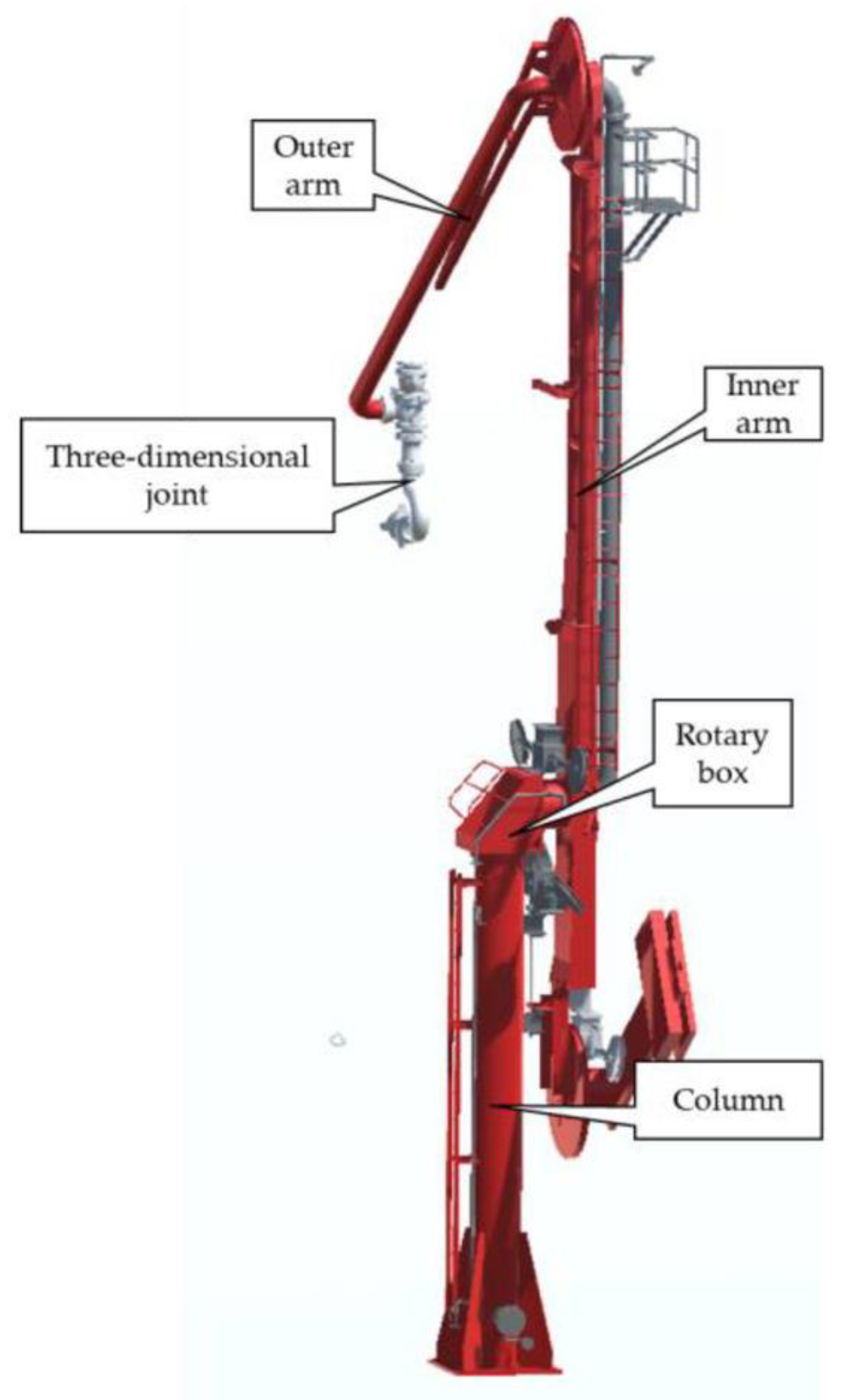
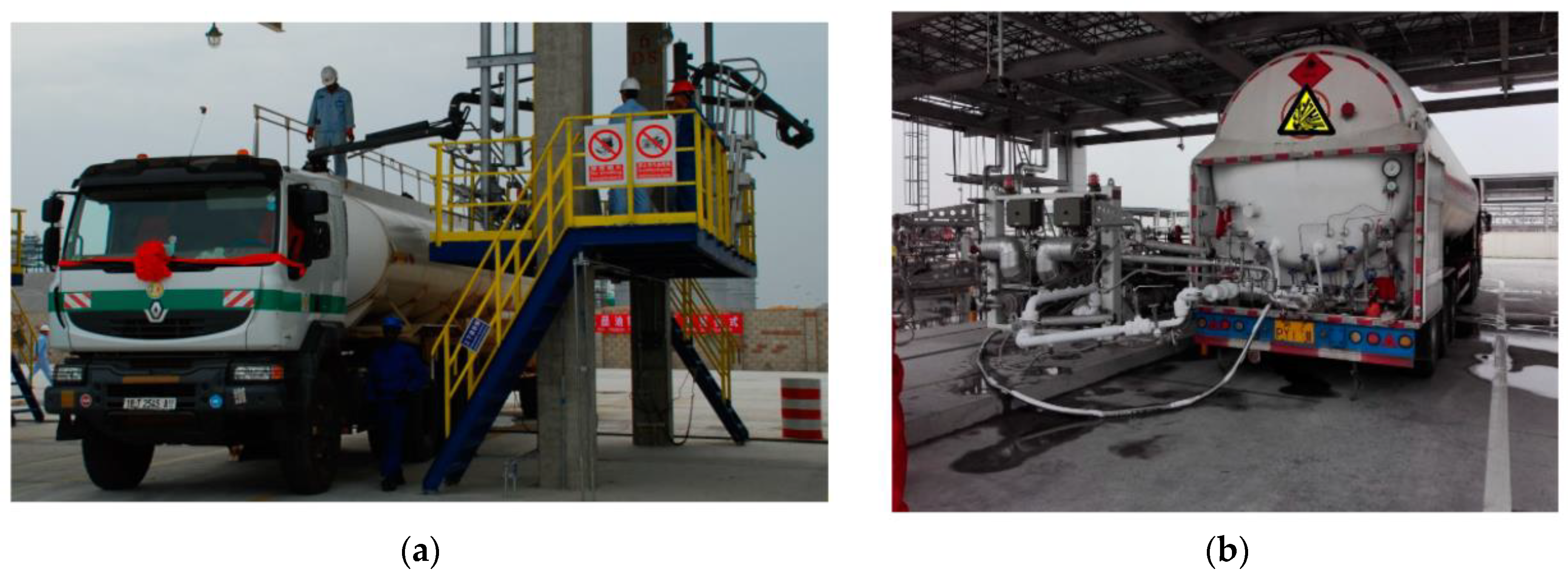
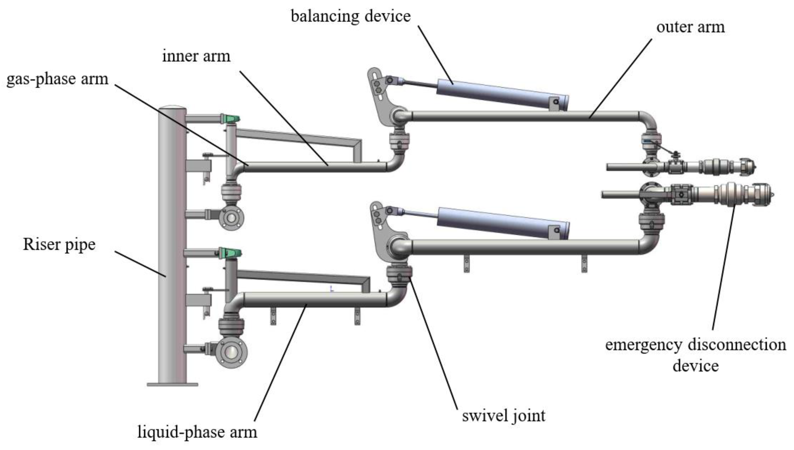
3.1. Overall Structure of the Land-Used Loading Arm

The land-used LNG loading arm is a device used to connect LNG transport vehicles to the pipelines of the receiving terminal and transfer LNG. The loading arm consists of a riser, rotary joints, a liquid-phase arm, a gas-phase arm, pipeline supports [12], a balancing device, an electrostatic-conducting device, an emergency disconnection device, etc. It is usually fixed on the loading platform or storage tank, with a relatively fixed structural form and a stable working environment. There are two loading methods for land-used loading and unloading arms: top-loading and bottom-loading; the case is shown in Figure 7.
The top-loading loading spout, also known as the upper-loading loading spout, is mainly used for the transfer of liquid or gas between the loading platform and the top of road or railway tank cars. It comes in two types, open-type and enclosed-type, and is connected to the tank car by inserting from the top. The bottom-loading loading spout, also known as the lower-loading loading spout, is mainly used for the transfer of liquid media between the loading skid and the tank car. It is connected to the outlet and the receiving port through a 90-degree angle flange connection, enabling quick docking and sealed loading and unloading, with a relatively high loading efficiency.
Currently, bottom-loading is mostly used for LNG loading and unloading. Compared with the top-loading method, bottom-loading is more convenient to operate, eliminating the need for workers to work at heights on the trestle. The bottom-loading method can achieve static liquid loading, greatly reducing the volatilization of LNG and the generation of static electricity. Moreover, the skid-mounted system for bottom-loading has a higher degree of automation, which can significantly improve work efficiency. The case is depicted in Figure 8.
To ensure smooth movement of the loading arm during operation, a balancer is usually used to balance the rotational torque of the outer arm. According to different balancing principles, there are seven types of balancing methods, including the spring cylinder type, air cylinder type, counterweight type, and counterweight–air cylinder type. Currently, the spring cylinder-type balancing method is widely adopted for land-based LNG loading and unloading arms. This method requires relatively little operating force. It utilizes the spring force generated by spring deformation to counteract the self-weight of the loading arm and external loads, thus achieving the balance of the loading arm. The structure diagram of the spring cylinder is shown in Figure 9.
When the loading arm is in a horizontal position, the schematic diagram of forces on the outer arm is shown in Figure 10. At this time, the moment of gravity of the outer arm and the extension arm relative to the swivel joint is equal to the tension moment of the spring cylinder on the outer arm, that is, the following obtains:
G · A E · cos θ = K · I · a · b c cos β
In order for the outer arm to remain in a horizontal state in any position, two conditions must be met: (1) β + θ = 90 ° ; (2) in any position, the compression amount of the spring in the spring cylinder is equal to the distance between point B and point C. Therefore, when installing the spring cylinder, the pre-compression amount of the spring should be equal to the length of BC when the outer arm moves upward to the highest point.
The sealing rings inside the rotary joint, due to factors such as wear and aging, can seriously affect the sealing performance of the rotary joint [51]. Therefore, when conducting the overall design of the loading arm and the design and selection of components, the convenience of replacing the sealing rings of the rotary joint should be taken into key consideration. At the same time, due to the flammable nature of LNG, the generation of static electricity and sparks should be avoided during the operation of the loading arm, and anti-static and fire-and-explosion-proof measures should be well implemented. Swivel joints and the emergency disconnection device remain key components of land-based LNG loading arms.

3.1.1. Rotary Joints and Sealing of the Land-Used Loading Arm

Common sizes of rotary joints for land-used LNG loading and unloading arms include DN50, DN80, DN100, etc., while those for marine loading and unloading arms are ND150, DN200, DN250, DN300, DN400, etc. There is a significant difference in size between the two, and there are many similarities and differences in terms of structure, sealing, and design requirements. The rotary joints of land-used loading and unloading arms are smaller in size, with a more compact internal structure, and it is easier to ensure the fitting accuracy between components. The rotary joints of marine loading and unloading arms are larger in size, capable of withstanding greater loads. At the same time, to avoid the impact of error accumulation during the manufacturing process on the sealing performance, higher machining accuracy is required [52].
In terms of sealing, both adopt a multi-layer sealing structure and use a nitrogen purging system to keep the raceway dry and prevent water vapor from freezing at low temperatures. However, marine LNG loading and unloading arms work in a bumpy, rocking, and humid marine environment for a long time, so they have higher requirements for the sealing performance, corrosion resistance, shock resistance, and structural strength of the rotary joints. The rotary joints of land-used and marine LNG loading and unloading arms have many similarities in basic structure, main functions, and technical requirements. However, due to the different working environments they face, their design characteristics also vary. Marine rotary joints focus more on shock resistance, stability, and complex sealing structures, while land-used rotary joints pay more attention to simplifying the structure and reducing costs while ensuring sealing performance.
The sealing forms of domestic cryogenic rotary joints in China mainly include active sealing, secondary dynamic sealing, auxiliary sealing, main static sealing, secondary static sealing, and nitrogen sealing. Among them, the most important and also the most prone to problems is the main sealing. Regarding the problem of main sealing leakage, Shanghai Qiyao Power Technology Co., Ltd. [53] proposed a double-leak-prevention structural design. The first-layer sealing selects liquid sealing, adopting a structure of two sealing ring retaining rings sandwiching one sealing ring. The retaining rings on both sides of the sealing ring can effectively alleviate the end-face wear of the sealing ring. The second-layer sealing adopts a metal knife-edge sealing structure, which is to add a metal ring in the shape of a knife-edge on the flange and use a metal gasket to assist in sealing. When the liquid sealing between the flange and the rotating shaft fails, the metal sealing can still prevent the leakage of LNG [54].
In the past six years, there have been several LNG leakage accidents at the Jiangsu LNG tank truck station, all of which were caused by problems with the static sealing device of the rotary joint. Such cryogenic rotary joints all choose spring-energized sealing rings as the main static seal and PTFE gaskets as the secondary static seal. The spring-energized sealing ring can still maintain good sealing performance when worn or under pressure, but the maintenance cost is high in case of failure. The PTFE sealing ring has excellent chemical stability and low-temperature flexibility, but as a secondary static sealing ring, its compensation performance is insufficient and it is prone to the cold-flow phenomenon. On this basis, PetroChina Jiangsu LNG Co., Ltd. [55] proposed to abandon the original double-sealing structure of the spring-energized main static sealing ring and the PTFE secondary static sealing ring, optimize the inner-ring structure of the rotary joint, and choose a graphite wound gasket with good sealing effect and compensation characteristics under low-temperature conditions as the sealing element; the case is depicted in Figure 11. This gasket is made of flexible graphite and stainless steel wound together and is widely used in flange joints of pressure vessels, pipelines, and other fields. It is an excellent sealing element [56].
When conducting the overall design of the loading arm and the design and selection of components, the convenience of replacing the sealing rings of the rotary joint should be given key consideration. The dynamic sealing rings of cryogenic rotary joints are mostly made of polytetrafluoroethylene with special springs inside [57]. However, due to factors such as aging and wear, they need to be replaced regularly. In traditional cryogenic rotary joints, the balls need to be removed to separate the rotating shaft from the housing, and then the sealing ring can be taken out for replacement, which is time-consuming and labor-intensive. To solve this problem, Lianyungang Jerry Automation Co., Ltd. [58] designed a new type of detachable cryogenic rotary joint (the case is depicted in Figure 12), which allows the replacement of the sealing ring without removing the balls. This design adopts a structure in which the raceway and the housing form a hole–shaft fit, enabling quick disassembly of the equipment for sealing ring replacement. After verification, it is found that the new structure reduces the replacement time to one eighth of the original. In terms of sealing, two-stage sealing is chosen, with end-face rotary sealing as the main seal and shaft-used rotary sealing as the secondary seal, ensuring reliable sealing effects.

3.1.2. Cryogenic Breakaway Valve

The emergency disconnection device is an important part of the loading arm. It can quickly and safely disconnect the connection between the loading arm and the interface in case of an emergency. Most of its core components use emergency shut-off ball valves. The land-used LNG loading arm has a small diameter, and a cryogenic breakaway valve is usually used as the emergency disconnection device; the case is depicted in Figure 11. This can effectively prevent accidents and is widely used in the loading and unloading between loading spouts, fluid loading and unloading arms, vehicles, and ships. Its working principle is that when the pressure in the pipeline is greater than the predetermined pressure, the breakaway valve breaks in the middle, and the one-way valves at both ends automatically close, preventing the pipeline from being pulled apart and the medium from leaking, thus avoiding secondary disasters. It is generally installed in the middle of the vertical pipe of the loading spout.
At present, there are mainly two structures for commonly used land-based ultra-low-temperature breakaway valves: the break-off bolt-type breakaway valve and the cable-disconnect-type breakaway valve. Among them, the break-off bolt-type breakaway valve is more widely used. This valve is equipped with check valves at both ends and is connected by break-off bolts. When the pulling force applied to the breakaway valve is greater than the set tensile value of the break-off bolt, the break-off bolt breaks instantly, and the check valves close instantly under the action of the spring to ensure that the breakaway valve does not leak. However, the break-off bolt-type breakaway valve has an obvious drawback, that is, it is difficult for the break-off bolt to meet the two requirements of “stable connection during normal operation” and “easy breakage in case of an emergency” simultaneously [59]. The critical fracture conditions for the fractured bolt are as follows:
σ a x i a l = F a p p l i e d A b o l t
τ = F a p p l i e d 2 π r n e c k t n e c k
When the axial stress is greater than the ultimate tensile strength of the bolt material or the shear stress in the necking area is greater than the shear strength of the material, the bolt will break.
To solve the problem of the uncertain fracture of the break-off bolt, Lianyungang Ocean Fluid Loading and Unloading Equipment Co., Ltd. added a reset and protection component to the original structure of the breakaway valve; the case is depicted in Figure 12. The reset and protection component includes a reset protection bolt and a connecting device, which is installed at the joint surface of the female valve component and the male valve component and can be flexibly connected and separated. By rotating the reset protection bolt, the male valve component and the female valve component are docked to prevent the break-off bolt component from accidentally breaking during the pipeline connection and disconnection operation. After the operation is completed, this component is separated to enable the break-off bolt component to work normally, greatly improving the safety performance of the break-off bolt-type breakaway valve. After the breakaway valve is pulled apart, the breakaway valve can be manually reset through the reset and protection component and can be used for repeated break-off.
Finding a balance between “stable connection during normal operation” and “easy disconnection in case of an emergency” will be the key focus in the future development of the break-off bolt-type breakaway valve. In addition to this, sealing is also a crucial aspect to be considered in the future development of LNG breakaway valves, that is, ensuring effective sealing of the two separated parts after disconnection. For example, Sreekanth et al. [60] developed a unique soft seal to replace the metal seal, reducing the leakage of the shut-off valve, selecting low-temperature-resistant stainless-steel material and subjecting it to cryogenic treatment to be used as the valve housing, using low-temperature-resistant polytetrafluoroethylene as the sealing material [61], lining it with an elastic stainless-steel skeleton, and combining it with an appropriate structural design to ensure no LNG leakage.

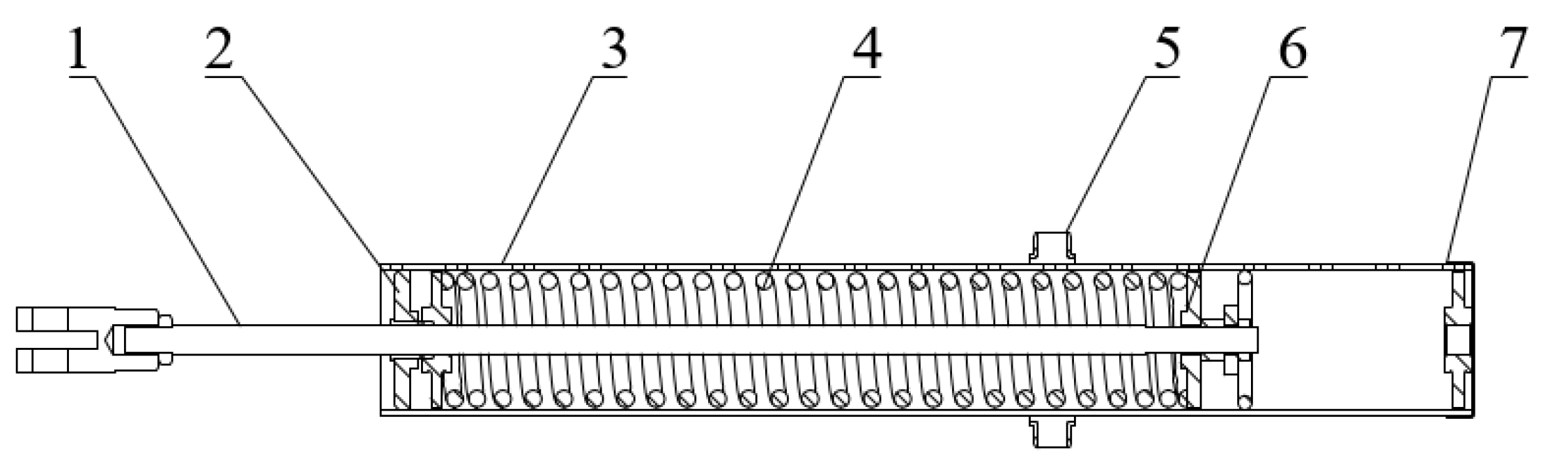
3.2. Land-Used Loading Arm Actuation and Its Intelligence and Automation

Due to differences in working environments and application requirements between marine loading and unloading arms and land-used loading and unloading arms, there are significant disparities in their intelligent development directions. Marine loading and unloading arms need to operate on swaying tankers, so their intelligent development focuses more on the precise positioning and docking of flange ports, as well as the remote monitoring and control of the loading and unloading arms. Land-used loading and unloading arms mostly operate in relatively stable environments, and their intelligent development should focus on improving the convenience, safety, and loading and unloading efficiency of the loading arm operations. For example, in unmanned tank truck loading and unloading operations, integrating functions such as quantitative loading controllers, license plate recognition systems [62,63], reservation systems, and skid-mounted systems [64] to achieve real-time monitoring throughout the process can greatly enhance loading and unloading efficiency and safety. The automatic LNG loading process is shown in Figure 13.
There are mainly two ways for the land-based loading arms to dock with the loading and unloading ports: manual dragging docking and mechanically driven automatic docking. The comparison between the two methods in terms of operation efficiency, docking precision, safety performance, cost, and environmental adaptability is shown in the following Table 1.
To improve loading efficiency, optimize the tank truck filling process, and enhance the intelligence and automation of tank truck filling, an intelligent management and control system for LNG tank trucks is of great importance. CNOOC Gas and Power Group Co., Ltd. [65] proposed an intelligent filling system for LNG tank trucks (the case is depicted in Figure 14), which includes a tank truck loading skid, a quick-connection interface with the tank truck, an upgrade of tank truck instruments, and a tank truck vehicle management process control system. This system enables remote monitoring and management of the tank truck filling situation through a PC. The loading skid is equipped with its own PLC control system, which uses GPRS [66] technology to interact with the computer, allowing one person to control the operations of multiple loading skids. Although this research has made the tank truck filling process more intelligent, there are still some issues in terms of automation. For example, the movement of the loading arm still requires manual dragging. Although the structure of the loading arm has been optimized to make the outer arm lighter, the operation mode still relies on manual intervention, and the full-automation docking of the loading arm cannot be achieved.
The automated docking technology for LNG loading arms aims to achieve rapid, safe, and unmanned operations between tank trucks and storage tanks or refueling stations, representing a critical development direction for LNG land transportation and refueling systems. The objectives of this technology include fully unmanned operations, adaptability to various complex environments, precise docking with the flange interface of tank trucks within a ±1 mm accuracy range, and emergency disconnection with valve closure within 0.5 s in case of contingencies. The key to realizing automated docking for loading arms lies in trajectory planning [67] and image processing [68].
(1) Trajectory Planning
Trajectory planning serves as the foundation for motion control and directly influences the accuracy of trajectory tracking in loading arms [69]. The trajectory planning of a loading arm involves determining its motion path under given constraints to ensure optimal smooth movement from the starting point to the target while avoiding obstacles. There are two methods for generating trajectories: joint-space planning and Cartesian-space planning. In joint-space planning, all joint variables are expressed as functions of time, and these joint functions—along with their derivatives—describe the robot’s intended motion. In contrast, Cartesian-space planning defines the position, velocity, and acceleration of the loading arm’s end-effector as functions of time. A comparison between these two approaches is presented in Table 2.
As shown in the table, Cartesian-space trajectory planning requires real-time inverse kinematics solutions to achieve trajectory tracking and obstacle avoidance, making it suitable for complex scenarios with collision avoidance requirements. In contrast, joint-space trajectory planning eliminates the need for inverse kinematics computations, offering simplified and efficient operations. This approach effectively circumvents robotic manipulator singularities and redundancy issues, thus being widely adopted in applications where strict end-effector path control is not critical, such as material handling.
Path planning algorithms generally fall into the following categories: the artificial potential field method, graph-based search algorithms, intelligent algorithms, and sampling-based algorithms. The artificial potential field method offers good real-time performance and is suitable for dynamic environments; however, it is prone to local minima and cannot find the global optimal solution. Graph-based search algorithms discretize the environment into nodes and use graph search strategies to find optimal paths. Typical algorithms include Dijkstra’s algorithm and the Dynamic Window Approach (DWA). These algorithms have high precision and are suitable for static, structured environments, but they become computationally complex in high-dimensional spaces, and their real-time performance may be affected. Intelligent algorithms rely on iterative search, with computational complexity growing exponentially as problem size increases. Their performance depends heavily on parameter settings, which are difficult to optimize.
Sampling-based algorithms construct a probabilistic graph to search for feasible paths by randomly sampling the environmental configuration space. Common ones include Probabilistic Roadmap (PRM) and Rapidly-exploring Random Tree (RRT). This type of algorithm can handle complex environments, but it has low sampling efficiency and poor adaptability to changing environments. To address these issues, Liang et al. [70] proposed an AGP-RRT* algorithm. It uses an adaptive biased probability sampling strategy to dynamically adjust the target deviation threshold, optimizing the sampling process and reducing the average running time by 87.34%. Huang et al. [71] put forward an optimized Informed-RRT* algorithm. By adding target deviation, an adaptive step-size, and a pruning strategy, it reduces the average number of sampled nodes by 88.39%, significantly lowering the computational complexity. In the future, the algorithms should be further optimized to reduce planning time, making them applicable to larger-scale dynamic environments.
In recent years, meta-heuristic algorithms have been applied to the trajectory planning problem in robotics. The trajectory planning of a robotic arm involves its end-effector smoothly moving from the starting point to the end point without hitting obstacles. Meta-heuristic algorithms have significant advantages in solving such problems. They can find the optimal solution in a large-scale exploration space without knowledge of the problem model. Currently, there are three popular meta-heuristic algorithms: the Particle Swarm Optimization (PSO) algorithm, Ant Colony Optimization (ACO) algorithm, and Genetic Algorithm (GA). Ekrem et al. [72] combined the PSO algorithm with quintic polynomial interpolation. The PSO algorithm ensures the continuity of quintic polynomial interpolation and trajectory control, enabling the robotic arm to achieve the optimal trajectory without hitting obstacles. However, compared with hybrid algorithms, the PSO algorithm has a slower computing time. Elgohr et al. [73] combined the global exploration advantage of the Whale Optimization Algorithm (WOA) with the GA and proposed a hybrid optimization technique, the Whale Genetic Algorithm (WGA). Compared with the WOA and GA, the WGA shortens the trajectory completion time by 44%, reduces energy consumption by 15%, and maintains compliance with kinematic and operational constraints. Optimizing algorithm parameters and creating hybrid models using two or more optimization methods can optimize the trajectory planning problem and obtain the global optimal solution, which is an important future development direction for trajectory planning. On the other hand, intelligent algorithms simplify complex computations. However, no current algorithm can simultaneously meet the requirements of global convergence, real-time solution, accuracy, universality, and simplicity of the solution process. Therefore, intelligent algorithms remain a key area of future research.
(2) Image Processing
Image processing technology enhances loading arm autonomy by extracting object coordinates from acquired images. It uses an inverse kinematics model to calculate joint angles required for the end-effector to reach the desired position and orientation, achieving precise docking with tanker flanges [74]. The accuracy of tanker flange identification directly impacts loading arm docking precision. Mei et al. [32] used the find Contours function in OpenCV to identify flange contours and obtained depth values via binocular cameras, achieving a maximum error within millimeters and a relative error of less than 1%. However, this error margin only applies to marine LNG loading arms, not land-based ones. Jiang Guangfa et al. [75] further developed an OpenCV-based flange center identification and positioning technique. This method first applies Gaussian and median filtering to images, then uses the Canny operator for binarization and Hough circle detection. Simulations of automatic loading arm docking on the ROS platform with Gazebo and Rviz revealed XYZ directional errors below 0.5 mm, meeting the precision requirements for land-based loading arms. Nonetheless, factors like lighting, oil contamination, and weather at loading sites currently prevent flange pose identification from meeting accuracy requirements. The identification algorithm needs further optimization to address these challenges.
To achieve the automatic docking of land-used LNG loading and unloading arms, in addition to visual recognition technology for positioning the target flange, sensor technology, motion control systems, and automated control algorithms also need to cooperate with each other. To precisely control the movement of the loading arm, first, sensors detect and identify the docking target to determine the initial positions of the loading arm and the target. A path-planning algorithm is applied to calculate the optimal movement path. Control algorithms such as PID control and fuzzy control are used to process the information fed back by the sensors. The PLC control system then controls the driving device to adjust the speed and direction of the loading arm’s movement in real time, thus completing the precise docking of the loading arm. For example, Cheng Xi [76] proposed an automatic positioning truss loading spout system. With PLC automatic control as the core and motors as the driving force, a laser alignment device is used to guide the automatic alignment of the loading spout and sealed loading.
During the loading process, traditional loading and unloading arms require manual operation by operators, which results in high labor intensity. In the case of emergencies, it is difficult for operators to handle the situation, and the risk is relatively high. Hu Xujie [77] improved the traditional loading arm by upgrading all manual valves on the arm to cryogenic pneumatic ball valves. Through the corresponding control programs in the controller, the automatic control of the valves is realized; the case is depicted in Figure 15. A hydraulic control system is selected as the driving mechanism of the loading arm. The hydraulic motor and gear transmission cooperate to drive the loading arm to the corresponding position. Then, the operator docks and fixes the end-interface of the loading arm with the interface of the tank truck. Song Xingwei et al. proposed a pneumatic-assisted loading arm. The rotation of the rotary joint is driven by an air cylinder, and a DCC quick-connect fitting is used to replace the loose flange, achieving rapid docking with the tank truck. This greatly reduces the labor intensity and improves the safety of operators and work efficiency.
With continuous technological innovation, the intelligent and automated development of loading and unloading arms is showing a flourishing situation. The intelligent loading and management system for tank trucks at the Nanshan LNG Receiving Terminal in Longkou, Shandong Province, passed the review, achieving a deep integration of informatization and digitization [78]. At the tank truck filling station of Qingdao Liquefaction Company, the robotic arm at the no. 12 skid position automatically positioned itself to the filling port of the tank truck. After intelligent safety inspection, it successfully completed the entire process of transporting liquefied natural gas. With the continuous development of visual recognition technology and the motion control system of loading and unloading arms, the automatic docking of loading and unloading arms will become more stable, precise, and reliable.

4. Challenges and Opportunities

4.1. Challenges

1. Material Limitations
Existing low-temperature alloys [79] and sealing materials struggle to balance long-term corrosion resistance (especially in marine environments) and cost-effectiveness, as detailed in Table 3.
2. Challenges in Dynamic Control of Loading Arms:
(1)
The challenge of LNG loading arms in flange recognition lies in high-precision and high-robustness visual perception within dynamic and complex environments. During tanker loading and docking, influenced by waves, wind loads, etc., hull sway causes continuous changes in the position and posture of the target flange. Traditional monocular or stereo vision is prone to parallax errors; affected by light, extreme weather, etc., the recognition accuracy of the target flange is poor;
(2)
Sway leads to continuous changes in the relative position between the hull and the loading arm. If the trajectory planning fails to compensate for the sway displacement in a timely manner, a collision will occur. Currently, in path-planning technology, no algorithm can simultaneously meet the requirements of global convergence, real-time solution, accuracy, universality, and simplicity of solution;
(3)
In low-temperature environments, the fluid viscosity of traditional hydraulic systems increases sharply, easily causing motion lag or stagnation. At present, the power module of loading arms is transitioning from traditional hydraulic power units to fully electric drive systems, used for swivel-joint rotation, triggering quick-connection devices (QC/DCs), and emergency release systems (ERS). This can effectively avoid hydraulic oil leakage risks and offers higher precision, shorter response times, etc. However, the motor must maintain stable output at −162 °C. Insulation materials of traditional motors may fail due to low-temperature hardening or shrinkage; at low temperatures, the lubrication system fails, exacerbating wear on gears, bearings, etc., and increasing torque requirements during motor start-up; temperature differences may cause condensed water inside the motor, which damages insulation materials after freezing; low temperatures reduce the resistance parameters of motor windings, affecting motor stability and leading to decreased efficiency and control accuracy;
(4)
The multi-degree-of-freedom joints of loading arms need to synchronously respond to hull sway, demanding a higher response speed from the control system. Traditional PID control is easily affected by coupling interference. Under hydraulic–electric hybrid drive, it is difficult to eliminate the overshoot phenomenon, and parameter tuning relies on experience;
(5)
The complex terminal environment causes communication delays, impacting the real-time control of loading arms.
3. Safety:
(1)
Currently, sealing measures for loading arms mostly adopt a double-seal structure, but under long-term operation at −162 °C, they still face challenges such as material shrinkage, elastic failure, and low-temperature embrittlement;
(2)
The pull-off valve faces conflicting demands between “stable connection” and “instant disconnection”, making it difficult to simultaneously meet the two conditions of “secure connection during normal operation” and “easy disconnection in emergencies”;
(3)
Emergency release devices generally have supporting hydraulics, and the hydraulic oil pump operates for long periods. When an emergency occurs, due to unstable hydraulics, the emergency release device cannot perform normal emergency disconnection;
(4)
At −162 °C, the combination of ice accumulation and salt–fog corrosion on the sealing surface accelerates wear. Current de-icing systems (such as nitrogen purging) are inefficient.

4.2. Opportunities

1. Upgrading of Intelligent and Automation Technologies
Marine and land-based loading arms both benefit from the wave of intelligence. For example, the world’s first set of marine loading arm products applied in Hainan Basuo Port in 2022, with the help of technologies such as vision recognition, BeiDou and 5G positioning, artificial intelligence, and deep learning, achieved intelligent flexible docking, one-key operation, remote status monitoring, and fault handling, greatly improving operation efficiency and safety, and matching the construction of smart ports. Land-based loading arms also introduce advanced sensors to real-time monitor parameters such as temperature, pressure, and flow, achieve automatic remote control, use artificial intelligence and machine learning to optimize operation parameters, adapt to different working conditions, reduce manual operation risks, and improve operation efficiency. In the future, loading arms are expected to further integrate automated process control technology, achieving automated operation throughout the entire process, from initial connection and precise flow regulation during the loading and unloading process to automatic disconnection and reset after loading and unloading is completed. Through deep integration with terminal or station control systems, the working mode of loading arms can be automatically adjusted according to parameters such as types of transport ships or tankers and LNG flow requirements, improving loading and unloading efficiency and reducing human operation errors. In the future, these intelligent technologies will continuously iterate, upgrade, and achieve deeper integration. For example, the accuracy of vision recognition technology will be further improved, enabling quick and accurate identification of the docking positions of transport ships or tankers under more complex light and weather conditions; artificial intelligence and deep learning algorithms will be continuously optimized, allowing loading arms to independently adjust operation parameters based on past operation data and real-time working conditions, achieving more efficient and safer operations, and fully meeting the unmanned and intelligent operation requirements of smart ports.
2. Development and Application of New Materials
Given the ultra-low-temperature characteristics (−162 °C) of LNG, developing new cryogenic-resistant and high-strength materials has become a trend. These materials reduce structural stress in low-temperature environments, enhance equipment durability and reliability, and minimize maintenance frequency and replacement costs. For marine loading arms, companies like Shandong Guanzhuo Heavy Industry adopt new structural designs and cryogenic-resistant materials to expand operational scope. Future applications will include advanced materials with superior cryogenic toughness, fatigue resistance, and low thermal expansion coefficients, improving equipment stability and service life. Land-based loading arms also leverage new high-performance materials: special alloy steel strengthens structural integrity, innovative thermal insulation materials reduce vaporization loss, and self-cleaning/corrosion-resistant materials enhance safety and reliability. Lightweight materials (e.g., carbon fiber composites) improve flexibility, reduce energy consumption, and decrease stress on supporting structures and drive components while maintaining performance. Additionally, advanced thermal insulation materials minimize LNG vaporization during operations, boosting energy efficiency. Self-cleaning and corrosion-resistant materials enable stable performance in harsh conditions, reducing leakage risks from corrosion. Looking ahead, advancements in materials science will drive the emergence and adoption of next-generation high-performance materials for loading arm manufacturing.
3. Innovations in High-Precision Positioning and Docking Technology
Marine loading arms achieve precise positioning and rapid docking through technologies such as vision recognition, laser guidance, 5G transmission, and BeiDou positioning. Equipped with intelligent docking systems, they can automatically adjust posture to avoid leakage caused by docking deviations. In land-based LNG loading and unloading operations, high-precision positioning and fast, accurate docking between loading arms and tankers are critical to improving operational efficiency and safety. In recent years, advanced positioning technologies like BeiDou satellite positioning, laser positioning, and vision recognition have made significant advancements and are increasingly applied to land-based LNG loading arms. Through the synergistic application of these technologies, loading arms can quickly and accurately identify the interface positions of ships or tankers, automatically adjust posture, and achieve precise docking, effectively preventing safety incidents such as leakage due to alignment errors. Simultaneously, the development of advanced docking mechanisms and sealing technologies ensures tight and reliable connections during docking, further enhancing operational safety and stability. For example, intelligent flexible docking devices can compensate for displacement caused by imprecise berthing, uneven ground, or swaying, ensuring sealing tightness and stability.
4. Integration with Emerging Energy Technologies
As the hydrogen energy industry grows, future marine LNG loading arms may need to expand functionality to accommodate hydrogen-powered transport ships. Through technological development, loading arms can adapt to hydrogen’s unique properties (e.g., ultra-low boiling point, high diffusivity) to enable compatibility or transition between LNG and hydrogen handling equipment, opening up new business opportunities. Both marine and land-based loading arms are actively integrating with the Internet of Things (IoT) and big data. Marine systems connect to IoT networks for device intercommunication, using big data analytics to uncover operational patterns and fault predictions, optimizing workflows. Land-based LNG loading arms leverage the IoT to upload real-time operational data to management platforms, enabling predictive maintenance via data analysis to ensure continuous operations and enhance overall efficiency.

5. Conclusions

This study comprehensively and thoroughly explores the evolution and future trends of liquefied natural gas (LNG) loading and unloading arms. Firstly, it introduces the background of the LNG industry and the significance of loading and unloading arms. Subsequently, it delves into two application scenarios, namely marine and land:
  • In the field of marine loading and unloading arms, it systematically analyzes the design of full-balance/rotary-balance/double-balance structures, the multi-sealing coordination mechanism of cryogenic swivel joints, the rapid-response principle of emergency disconnection devices, and the intelligent docking technology based on vision–multi-sensor fusion;
  • In the field of land-based loading and unloading arms, it focuses on the mechanical optimization model of the spring cylinder balance system, the sealing materials of cryogenic butterfly valves, the automated control strategies for multi-vehicle parallel loading and unloading, and the unmanned docking technology based on trajectory planning algorithms.
The research also reveals the challenges faced by key technologies such as material failure at low temperatures, control accuracy under dynamic loads, and sealing reliability in complex environments. It proposes technical paths for future research from dimensions such as structural lightweighting, control intelligence, and material high-performance-ization.
(1) Innovative Contributions
The research content of this paper is interdisciplinary, breaking through the single-perspective of traditional mechanical engineering. It combines fluid mechanics, materials science, control engineering, and intelligent algorithms to construct a four-in-one technical analysis framework of “structural design–sealing mechanism–intelligent control– safety protection”. For example, in the research on swivel joint sealing, it for the first time expounds on the coupling model between material shrinkage rate and sealing pre-tightening force in a low-temperature environment, as well as the innovative solution of “dynamic compensation of the main seal + redundant protection of the secondary seal + collaborative nitrogen purging”, providing a method to solve the elastic failure problem of the traditional double-sealing structure at −162 °C. By comparing and analyzing the equipment data of international mainstream manufacturers such as FMC, SVT, and Kanon, and combining with the engineering practices of domestic LNG receiving stations, it elaborates on the optimized formula for the anti-overturning moment of loading arms suitable for complex sea conditions (such as the moment of inertia distribution model of the double-balance system) and verifies the flange interface recognition algorithm based on the YOLOv8 deep-learning model. This algorithm maintains a docking accuracy of ±1 mm under ±30° pitch angles and sea state 6 conditions, filling the research gap in intelligent docking technology in dynamic environments in China. Aiming at the current situation of domestic LNG loading and unloading equipment relying on imports, it sorts out the differences between domestic and international standards such as ISO 20519 [81] and GB/T 44412 [82]. Combining with accident cases from LNG terminals in Lianyungang, Tangshan, etc., it proposes material selection standards suitable for the high-humidity and salt–fog corrosion environment along China’s coast (such as low-temperature toughness indicators for nickel-based alloys and cold-flow rate control parameters for polytetrafluoroethylene sealing rings), providing a key basis for the standardized design of domestic equipment.
(2) Scientific Research Contributions
This paper expounds on the multi-field coupling model of the mechanical structure–sealing system–control system of loading arms in a low-temperature environment, revealing the influence of temperature gradients on the contact stress of swivel joints, the viscous resistance of hydraulic systems, and the signal transmission of sensors. It provides a theoretical tool for reliability analysis under extreme working conditions in the field of scientific research. It proposes a three-level research method of “qualitative analysis–numerical simulation–engineering verification”. For example, it uses ANSYS Workbench 13.0 to simulate the stress of fracture bolts in emergency disconnection devices and corrects the model by combining with real-ship collision test data, forming a closed-loop verification system from basic research to engineering application. In the field of intelligent control, it introduces digital twin technology into the remote monitoring of loading arms, realizing the real-time state mapping between the three-dimensional model and the physical equipment. In the field of materials, it demonstrates the feasibility of carbon fiber-reinforced composite materials in the lightweight design of land-based loading arms, providing new ideas for solving the problem of insufficient strength of traditional aluminum alloys.
(3) Academic Impact
This paper not only systematically combs the development context of LNG loading and unloading arm technology but also provides reproducible experimental parameters and comparison benchmarks for follow-up research through the quantitative analysis of key indicators such as the path optimization efficiency of the improved RRT* algorithm (an 87% improvement) and the image recognition accuracy (the error of the binocular vision system is controlled within 0.5 mm). The proposed technical route of “emphasizing both intelligent upgrading and reliability enhancement” points out the direction for interdisciplinary research in this field, helping to promote the paradigm shift in LNG loading and unloading equipment from “manual operation” to “autonomous intelligence”, and has a positive significance for improving the international technical level of clean energy equipment.

Author Contributions

Conceptualization, M.L. and J.W.; methodology, J.W.; software, Y.Z.; validation, H.Z., J.Z. and K.Z.; investigation, J.W.; resources, J.W.; data curation, J.W.; writing—original draft preparation, J.W.; writing—review and editing, M.L.; project administration, M.L.; funding acquisition, M.L. All authors have read and agreed to the published version of the manuscript.

Funding

This research was funded by Lianyungang Science and Technology Plan grant number CG2417. The APC was funded by Mingqin Liu.

Acknowledgments

Thank you to Lianyungang Top Technology Co., Ltd. for providing practical opportunities for the research of this article.

Conflicts of Interest

The authors declare no conflict of interest.

References

  1. Kanbur, B.B.; Xiang, L.; Dubey, S.; Choo, F.H.; Duan, F. Cold utilization systems of LNG: A review. Renew. Sustain. Energy Rev. 2017, 79, 1171–1188. [Google Scholar] [CrossRef]
  2. Iqbal, J.; Khan, Z.H. The potential role of renewable energy sources in robot’s power system: A case study of Pakistan. Renew. Sustain. Energy Rev. 2017, 75, 106–122. [Google Scholar] [CrossRef]
  3. Yuan, L. Analysis of current development status and prospects of China’s natural gas chemical industry. Low-Carbon Chem. Chem. Eng. 2024, 49, 105–112. [Google Scholar]
  4. Gao, Y.; Wang, B.; Hu, Y.; Gao, Y.; Hu, A. Development of China’s natural gas: Review 2023 and outlook 2024. Nat. Gas Ind 2024, 44, 166–177. [Google Scholar]
  5. Stavrou, D.I.; Ventikos, N.P.; Mavrakos, S.A. Dynamic monitoring of risk failure of loading arms for LNG site-by-site operations. In Proceedings of the ISOPE International Ocean and Polar Engineering Conference, Rhodes, Greece, 26 June–2 July 2016; p. ISOPE-I-16-410. [Google Scholar]
  6. Liu, Y.; Yang, L.; Jing, Y.X. Research and analysis on the technical status of LNG handling system. Pet. Chem. Equip. 2020, 23, 44–48. [Google Scholar]
  7. Orellana, F.; Durán, O.; Vergara, J.I.; Arata, A. Maintainability Analysis of Remotely Operated LNG Marine Loading Arms Based on UNE 151001 Standard. Machines 2024, 12, 407. [Google Scholar] [CrossRef]
  8. Li, T.T.; He, X.; Gao, P. Analysis of offshore LNG storage and transportation technologies based on patent informatics. Clean. Eng. Technol. 2021, 5, 100317. [Google Scholar] [CrossRef]
  9. Liang, X. Research and Design of Automatic Centering and Hydraulic Control System for Fluid Handling Arm. Master’s Thesis, Northeast Forestry University, Harbin, China, 4 January 2023. [Google Scholar]
  10. Sun, L.P.; Zhang, S.K. The Development History of Fluid Loading and Unloading Equipment in China. Chem. Eng. Manag. 2013, 18, 172. [Google Scholar] [CrossRef]
  11. Dirik, C.; Biak, D.R.A.; Ibrahim, N.N.L.N. Externally initiated event in sequential risk assessment for the onshore LNG marine loading arm unit. J. Loss Prev. Process Ind. 2022, 75, 104717. [Google Scholar] [CrossRef]
  12. Li, M.; Zhou, Y.; Yu, B.; Shi, G.Z.; Xia, H.B. Low-temperature heat transfer and stress analysis of LNG loading arm pipeline supports. J. Phys. Conf. Ser. 2022, 2395, 012002. [Google Scholar] [CrossRef]
  13. Chen, G.X.; Jin, Y.S. Key technologies in the assembly process of LNG unloading arm. Oil Gas Storage Transp. 2015, 34, 874–878. [Google Scholar]
  14. Hu, X.; Yu, B. Structural optimization design of LNG unloading arm based on finite element analysis. In Proceedings of the Eighth International Conference on Electromechanical Control Technology and Transportation (ICECTT 2023), Hangzhou, China, 19–21 May 2023; pp. 175–182. [Google Scholar]
  15. Xiang, R.; Feng, W.; Song, S.; Zhang, H. Automated Docking System for LNG Loading Arm Based on Machine Vision and Multi-Sensor Fusion. Appl. Sci. 2025, 15, 2264. [Google Scholar] [CrossRef]
  16. Wang, X.B. Design of counterweight balancing system for LNG loading and unloading arm. Hoisting Conveying Mach. 2020, 8, 81–85. [Google Scholar]
  17. Meng, J.; Feng, S.G. Development, Testing and Research of Low-temperature and Fast connection Devices. Mech. Electr. Inf. 2021, 27, 45–48. [Google Scholar] [CrossRef]
  18. Long, L.; Bo, M.; Qi, W. Research on Influences of Dike Dam on the Law of LNG Release and Dispersion. New Technol. New Process 2014, 12, 115–118. [Google Scholar]
  19. Wang, L.M.; Huang, W.D.; Xu, X.T. Experimental Research on Large-diameter LNG Rotary Joints. Public Commun. Sci. Technol. 2014, 9, 187–188. [Google Scholar]
  20. Tao, W.; Jiali, W. Analysis of Manufacture and Leakage for Low Temperature Crane Tubes. New Technol. New Process 2022, 10, 1–4. [Google Scholar] [CrossRef]
  21. Huang, C.C. Comparative Analysis of the Application of LNG Loading Arm Rotary Joints. Plant Maint. Eng. 2020, 11, 127–128. [Google Scholar] [CrossRef]
  22. Pereira, E.; Alkali, B.; Niculita, O. Liquefied natural gas plant maintenance: A case study of marine loading arms seal failure analysis. In Proceedings of the 30th European Safety and Reliability Conference and 15th Probabilistic Safety Assessment and Management Conference: ESREL 2020 and PSAM15 2020, Venice, Italy, 21–26 June 2020; pp. 843–848. [Google Scholar]
  23. Wang, X.C.; Xu, J. Analysis of the Process Technology and the Inevitability of Domestication of LNG Marine Loading Arms. China High-Tech Enterp. 2015, 8, 82–85. [Google Scholar] [CrossRef]
  24. Yu, Y.; Hong, L.; Fuhua, S.; Cheng, Z.; Rican, Y. Analysis of the Process Technology and the Necessity of Domestication of LNG Marine Loading Arms. Agric. Equip. Technol. 2017, 43, 40–41. [Google Scholar]
  25. Pan, H.T. Application of Loading Arm Emergency Release System (ERS) on Oil & Gas Terminals. Port Waterw. Eng. 2004, 10, 50–53. [Google Scholar] [CrossRef]
  26. Paquet, S.; Lamourette, C.; Auburtin, E.; Hellesmark, S.; Thorsen, T. Safe LNG loading of conventional LNG carriers in severe open sea environments. In Proceedings of the Offshore Technology Conference Asia, Kuala Lumpur, Malaysia, 22–25 March 2016; p. D021S013R002. [Google Scholar]
  27. Mei, J.; Feng, W.; Liang, Z. Improved Design of LNG Marine Loading Arm Docking Method Based on TRIZ Theory. Appl. Sci. 2023, 13, 4525. [Google Scholar] [CrossRef]
  28. Nijak, M.; Skrzypczyński, P.; Ćwian, K.; Zawada, M.; Szymczyk, S.; Wojciechowski, J. On the importance of precise positioning in robotised agriculture. Remote Sens. 2024, 16, 985. [Google Scholar] [CrossRef]
  29. Zhou, Q.; Yamada, S.; Robbe, P.; Charlet, D.; Itoh, R.; Nakao, M.; Suzuki, S.; Kunigo, T.; Jules, E.; Plaige, E. PCI-express based high-speed readout for the Belle II DAQ upgrade. IEEE Trans. Nucl. Sci. 2021, 68, 1818–1825. [Google Scholar] [CrossRef]
  30. Islam, A.; Asikuzzaman, M.; Khyam, M.O.; Noor-A-Rahim, M.; Pickering, M.R. Stereo vision-based 3D positioning and tracking. IEEE Access 2020, 8, 138771–138787. [Google Scholar] [CrossRef]
  31. Li, Z.; Li, S.; Shi, C.; Yang, J.; Chen, R. Automatic Docking System for Ship Shore LNG Loading and Unloading Arms. CN111915718A. Available online: http://epub.cnipa.gov.cn/Dxb/PatentDetail (accessed on 9 April 2025).
  32. Zheng, Y.; Liu, P.; Qian, L.; Qin, S.; Liu, X.; Ma, Y.; Cheng, G. Recognition and depth estimation of ships based on binocular stereo vision. J. Mar. Sci. Eng. 2022, 10, 1153. [Google Scholar] [CrossRef]
  33. Tian, X.; Liu, R.; Wang, Z.; Ma, J. High quality 3D reconstruction based on fusion of polarization imaging and binocular stereo vision. Inf. Fusion 2022, 77, 19–28. [Google Scholar] [CrossRef]
  34. Ma, Y.; Li, Q.; Chu, L.; Zhou, Y.; Xu, C. Real-time detection and spatial localization of insulators for UAV inspection based on binocular stereo vision. Remote Sens. 2021, 13, 230. [Google Scholar] [CrossRef]
  35. Zheng, Y.; Zhao, J.; Fang, S.; Wang, M.; Zhang, Q. Research on Automatic Locating Method for Large Hydraulically-Driven Loading Arm Based on Visual Servo; IEEE: New York, NY, USA, 2018; pp. 855–860. [Google Scholar] [CrossRef]
  36. He, L.; Chen, Y.; Zhao, J. Automatic Docking Recognition and Location Algorithm of Port Oil Loading Arm Based on 3D Laser Point Cloud. In Proceedings of the 2020 IEEE International Conference on Mechatronics and Automation (ICMA), Beijing, China, 13–16 October 2020; pp. 615–620. [Google Scholar]
  37. Cognex Launches the In-Sight 3D-L4000 Vision System. Electronics Quality 2021, 78–79. Available online: https://qikan.cqvip.com/Qikan/Article/Detail?id=7103894052 (accessed on 12 February 2025).
  38. Yu, Q.; Hu, L.; Alzahrani, B.; Baranawi, A.; Alhindi, A.; Chen, M. Intelligent visual-IoT-enabled real-time 3D visualization for autonomous crowd management. IEEE Wirel. Commun. 2021, 28, 34–41. [Google Scholar] [CrossRef]
  39. Lee, J.; Ni, J.; Singh, J.; Jiang, B.; Azamfar, M.; Feng, J. Intelligent maintenance systems and predictive manufacturing. J. Manuf. Sci. Eng. 2020, 142, 110805. [Google Scholar] [CrossRef]
  40. Peng, R.G.; Zhu, B.R.; Li, H.; Chen, X.H. Analysis of Using Domestic LNG Unloading Arms in Domestic LNG Terminals. Constr. Mach. Equip. 2024, 55, 196–200+115–116. [Google Scholar]
  41. Li, Y. Research and application of deep learning in image recognition. In Proceedings of the 2022 IEEE 2nd international conference on power, electronics and computer applications (ICPECA), Shenyang, China, 21–23 January 2022; pp. 994–999. [Google Scholar]
  42. Tian, Y. Artificial intelligence image recognition method based on convolutional neural network algorithm. IEEE Access 2020, 8, 125731–125744. [Google Scholar] [CrossRef]
  43. Jacob, I.J.; Darney, P.E. Design of deep learning algorithm for IoT application by image based recognition. J. ISMAC 2021, 3, 276–290. [Google Scholar] [CrossRef]
  44. Rawat, R.; Yadav, R. Big data: Big data analysis, issues and challenges and technologies. In Proceedings of the IOP Conference Series: Materials Science and Engineering, Bapatla, Andhra, 7–8 May 2021; p. 012014. [Google Scholar]
  45. Botín-Sanabria, D.M.; Mihaita, A.-S.; Peimbert-García, R.E.; Ramírez-Moreno, M.A.; Ramírez-Mendoza, R.A.; Lozoya-Santos, J.d.J. Digital twin technology challenges and applications: A comprehensive review. Remote Sens. 2022, 14, 1335. [Google Scholar] [CrossRef]
  46. Zhong, D.; Xia, Z.; Zhu, Y.; Duan, J. Overview of predictive maintenance based on digital twin technology. Heliyon 2023, 9, e14534. [Google Scholar] [CrossRef]
  47. Ye, W.C. Railway Transportation of LPG: A Risk Assessment of LPG in the Course of Load-and-Unload. Adv. Mater. Res. 2014, 1030–1032, 2078–2081. [Google Scholar]
  48. Jiang, W.M. Analysis of Storage and Transportation Issues of Liquefied Natural Gas (LNG). China Pet. Chem. Stand. Qual. 2021, 41, 7–9. [Google Scholar]
  49. Gang, L.; Yan, H. On the selection of closed quantitative loading mode of large and small crane pipes for railway transportation of light oil products. Chem. Eng. Manag. 2017, 14. Available online: https://kns.cnki.net/kcms2/article/abstract?v=O_n6o0K2eiodvivkUjBJm9W3pEodboT4bpCl6daiT2j8U6WE_DDQaY1Bdj630axtDa0bgSTaWY8mRYy2VJPznAuiQwhkM4eL6wCcRfWbw4Rklxt1ZAc8Df9pL3h_e0aP43q6dYt3PWwSv7Nm-j1ghfMw5esZoEW804ajewn6DCLBzv_KEIoDgmv79m1dbDI_-SugFWVkRx0=&uniplatform=NZKPT&language=CHS (accessed on 9 April 2025).
  50. Liu, M.Q.; Li, Z.Z.; Liu, J.; Ma, Z.G.; Xu, M.L.; Lyu, S.K. Research on identification method for interface flange in automatic docking system of fluid loading and unloading arm for bottom loading. Appl. Sci. 2022, 12, 3037. [Google Scholar] [CrossRef]
  51. Wróblewski, P. Technology for Obtaining Asymmetries of Stereometric Shapes of the Sealing Rings Sliding Surfaces for Selected Anti-Wear Coatings; SAE Technical Paper: Pittsburgh, PA, USA, 2020; pp. 0148–7191. [Google Scholar]
  52. Zhang, S.; Dong, Y.; Yang, K. Finite element analysis of a dry quick coupling device for an LNG hose conveying system. In Proceedings of the Sixth International Conference on Information Science, Electrical, and Automation Engineering (ISEAE 2024), Wuhan, China, 19–21 April 2024; pp. 514–520. [Google Scholar]
  53. Lin, B.; Sao, X.F.; Li, Y.M.; Li, Y.J.; Du, K.J. Research and Design of Low Temperature Swivel Joint for LNG Loading and Pry. Agric. Equip. Technol. 2020, 46, 38–41. [Google Scholar]
  54. Ma, C.; Cheng, Y.C.; Liu, W. Failure Analysis and Improvement of Sealing for Liquefied Ammonia Loading and Unloading Crane Pipes. Plant Maint. Eng. 2019, 9, 71–73. [Google Scholar] [CrossRef]
  55. Lei, F.S.; Guo, H.T. Failure mechanism research and optimization design of low temperature rotary joint of LNG loading arm. Gen. Mach. 2018, 8, 16–18+24. [Google Scholar] [CrossRef]
  56. Rino, N.N. Effective modeling of spiral wound gasket with graphite filler in gasketed flange joint subjected to bending loads. Mater. Today Proc. 2021, 44, 2199–2204. [Google Scholar]
  57. Yong, Q. Application of Polytetrafluoroethylene on Fluid Sealing. Petro-Chem. Equip. Technol. 2005, 3, 50-53+69. [Google Scholar]
  58. Shang, Y.W.; Yao, G.C.; Wang, W.H.; Ma, R. Design of New Low Temperature Detachable Swivel Joint. Nat. Gas Oil 2015, 33, 80–82+13. [Google Scholar]
  59. Wu, Y.F.; Wei, H.X.; Wu, S.P.; Cheng, J.; Zhou, J.; Wang, J.R.; Zeng, X.B.; Sheng, W. Technical Status and Standard Requirement Analysis of Marine Ultra Low Temperature Break Valve for LNG Transmission. Shipbuild. Stand. Qual. 2019, 5, 21–25+31. [Google Scholar]
  60. Sreekanth, N.; Sankaran, S.; Kenned, J.J. Development of soft seal and experimental investigation of soft seated safety relief valves for cryogenic applications. Cryogenics 2025, 146, 104005. [Google Scholar] [CrossRef]
  61. Moore, B.; Maddocks, J.; Miller, F. Development and testing of a passive check valve for cryogenic applications. Cryogenics 2014, 64, 244–247. [Google Scholar] [CrossRef]
  62. Izidio, D.M.; Ferreira, A.P.; Medeiros, H.R.; Barros, E.N.d.S. An embedded automatic license plate recognition system using deep learning. Des. Autom. Embed. Syst. 2020, 24, 23–43. [Google Scholar] [CrossRef]
  63. Shi, H.; Zhao, D. License plate recognition system based on improved YOLOv5 and GRU. IEEE Access 2023, 11, 10429–10439. [Google Scholar] [CrossRef]
  64. Zhang, C.; Song, P.; Xiao, L.; Zhang, Y.; Wang, X.; Hou, J.; Wang, X.; Lu, L. Research and development of on-site small skid-mounted natural gas to hydrogen generator in China. Int. J. Hydrogen Energy 2023, 48, 18601–18611. [Google Scholar] [CrossRef]
  65. Zhou, S.H.; Song, K.; Chen, H.P. Design and research on smart loading system of LNG road tanker. Nat. Gas Oil 2021, 39, 38–43. [Google Scholar]
  66. Yang, L.; Zhang, Y.; Ruan, H. Research on BeiDou satellite positioning algorithm based on GPRS technology. Mob. Inf. Syst. 2021, 2021, 2468267. [Google Scholar] [CrossRef]
  67. Mir, I.; Gul, F.; Mir, S.; Khan, M.A.; Saeed, N.; Abualigah, L.; Abuhaija, B.; Gandomi, A.H. A survey of trajectory planning techniques for autonomous systems. Electronics 2022, 11, 2801. [Google Scholar] [CrossRef]
  68. Wang, J.; Li, X.; Jin, Y.; Zhong, Y.; Zhang, K.; Zhou, C. Research on image recognition technology based on multimodal deep learning. In Proceedings of the 2024 IEEE 2nd International Conference on Image Processing and Computer Applications (ICIPCA), Shenyang, China, 28–30 June 2024; pp. 1363–1367. [Google Scholar]
  69. Dai, Y.; Xiang, C.; Zhang, Y.; Jiang, Y.; Qu, W.; Zhang, Q. A Review of Spatial Robotic Arm Trajectory Planning. Aerospace 2022, 9, 361. [Google Scholar] [CrossRef]
  70. Liang, J.; Luo, W.; Qin, Y. Path Planning of Multi-Axis Robotic Arm Based on Improved RRT∗. Comput. Mater. Contin. 2024, 81, 1009–1027. [Google Scholar] [CrossRef]
  71. Huang, A.; Yu, C.; Feng, J.; Tong, X.; Yorozu, A.; Ohya, A.; Hu, Y. A motion planning method for winter jujube harvesting robotic arm based on optimized Informed-RRT* algorithm. Smart Agric. Technol. 2025, 10, 100732. [Google Scholar] [CrossRef]
  72. Ekrem, Ö.; Aksoy, B. Trajectory planning for a 6-axis robotic arm with particle swarm optimization algorithm. Eng. Appl. Artif. Intell. 2023, 122, 106099. [Google Scholar] [CrossRef]
  73. Elgohr, A.T.; Khater, H.A.; Mousa, M.A. Trajectory Optimization for 6 DOF Robotic Arm Using WOA, GA, and Novel WGA Techniques. Results Eng. 2025, 25, 104511. [Google Scholar] [CrossRef]
  74. Islam, R.U.; Iqbal, J.; Manzoor, S.; Khalid, A.; Khan, S. An autonomous image-guided robotic system simulating industrial applications. In Proceedings of the 2012 7th International Conference on System of Systems Engineering (SoSE), Genova, Italy, 16–19 July 2012; pp. 344–349. [Google Scholar]
  75. Jiang, F.; Chen, K.; Chen, Y.; Tian, C. Trajectory planning and automatic docking of LNG five-axis loading arm. Eng. Comput. 2024, 41, 2118–2133. [Google Scholar] [CrossRef]
  76. Xi, C.; Hongzhou, C.; Jiangtao, L.; Jingtao, D.; Yue, X. Application of automatic positioning truss crane tube system in condensate loading trestle. Petrochem. Ind. Technol. 2022, 29, 136–137. [Google Scholar]
  77. Bin, W.; Yong, W.; YuanJie, Z. Application Research of LNG Semi Automatic Loading and Unloading Arm. Mech. Eng. Technol. 2022, 11, 699–707. [Google Scholar] [CrossRef]
  78. National Pipeline Network Group Construction Project Management Branch. The Intelligent Loading and Management System for Tank Trucks at the Shandong Longkou Nanshan LNG Receiving Terminal Has Passed the Review. Available online: https://gas.in-en.com/html/gas-3680272.shtml (accessed on 15 November 2024).
  79. Zhou, J.J.; Zhang, X.X.; Qian, M.F.; Li, A.B.; Geng, L. Research Progress on Low-Temperature Performance of Common Structural Materials. J. Aeronaut. Mater. 2024, 44, 72–86. [Google Scholar] [CrossRef]
  80. Yao, J.; Zhao, G.; Niu, X.; Zhang, R.; Zhang, J. Wear mechanism and underground structure of Inconel 625 nickel-based alloy sliding against WC-Co in seawater. Wear 2024, 546, 205365. [Google Scholar] [CrossRef]
  81. ISO 20519:2021(E); Ships and Marine Technology—Specification for Bunkering of Liquefied Natural Gas Fuelled Vessels. ISO Copyright Office: Geneva, Switzerland, 2021.
  82. GB/T 44412-2024; Ships and Marine Technology—Specification for Bunkering of Liquefied Natural Gas Fuelled Vessels. Standardization Administration of China: Beijing, China, 2024.
Figure 1. The development history of LNG loading and unloading arms.
Applsci 15 04316 g001
Figure 2. Marine loading and unloading arm in working condition. Adapted from [15].
Applsci 15 04316 g002
Figure 3. Three balancing types of marine loading and unloading arms. (a) Full-balanced type; (b) rotary-balance type; (c) double-balance type.
Applsci 15 04316 g003
Figure 4. Rotary joint structure diagram.
Applsci 15 04316 g004
Figure 5. Internal ring-shaped insulated cavity structure diagram.
Applsci 15 04316 g005
Figure 6. Working schematic diagram of LNG marine loading arm docking with LNG ship. 1—LNG marine loading arm control box; 2—LNG marine loading arm; 3—end joint of the LNG marine loading arm; 4—land operator; 5—wave; 6—LNG ship; 7—transportation pipe interface; 8—ship operator; 9—wind. Adapted from [27].
Applsci 15 04316 g006
Figure 7. Land-based LNG loading arm [16]. (a) Top-loading loading arm; (b) bottom-loading loading arm.
Applsci 15 04316 g007
Figure 8. Structure diagram of land-based LNG loading arm.
Applsci 15 04316 g008
Figure 9. Structure diagram of spring cylinder. 1—pull rod; 2—spring-loaded positioning plates; 3—cylinder block; 4—spring; 5—spring cylinder lugs; 6—clapboard; 7—end caps.
Applsci 15 04316 g009
Figure 10. Schematic diagram of forces on the outer arm when it is horizontal.
Applsci 15 04316 g010
Figure 11. Cryogenic breakaway coupling.
Applsci 15 04316 g011
Figure 12. Structure schematic diagram of rupture bolt breakaway coupling with protective components. 1—female valve component; 2—reset and protection component; 3—break-off bolt component; 4—male valve component; 5—signal generation component.
Applsci 15 04316 g012
Figure 13. The automatic LNG loading process.
Applsci 15 04316 g013
Figure 14. Intelligent management control system structure framework diagram for LNG tank trucks.
Applsci 15 04316 g014
Figure 15. Hydraulic semi-automated loading arm.
Applsci 15 04316 g015
Table 1. Performance comparison between manual dragging docking and mechanically driven automatic docking.
Comparative DomainAutomatic DockingManual Docking
Operational efficiencyFully automated, unmanned operation with short single loading/unloading timeManual skill-dependent operations with long loading/unloading time
Docking accuracyVisual positioning, both axial and angular deviations are relatively smallManual visual docking, high deviation
Safety performanceReal-time sensor surveillance, EBS achieves a 0.5 s response timeHigh risk of human error, high accident rate
CostLow labor cost, long-term operation and maintenance costGreat demand for operators, long training cycle for manual operations
Environmental adaptabilityStrong anti-interference capabilityOperational challenges in cold weather
Table 2. Comparison of trajectory planning for robotic arms in joint space or Cartesian space.
Comparative
Domain
Joint SpaceCartesian Space
Task typesPoint-to-point, high-speed motionTrajectory tracking, high-precision motion control
Computational complexityOnly the joint differences are required, inverse kinematics solution is not neededReal-time inverse kinematics solution
PrecisionThe end trajectory may have errors due to mechanical errors or flexible deformationPlan the end trajectory directly, the end path is strictly controllable
Obstacle avoidance capabilityDifficult to directly perceive the relationship between environmental obstacles and the end pathCombine with the environmental model to avoid obstacles
Motion smoothnessThe joint motion parameters are directly controlled, the speed and acceleration are continuous The end path is smooth, the joint movement may change abruptly
Table 3. Advantages and disadvantages of low-temperature materials for loading arms.
Material TypeAdvantagesDisadvantagesApplication Scenarios
Austenitic stainless steelGood low-temperature toughness and strong
corrosion resistance
High density, prone to stress corrosion when welded
improperly
Rotary joints, pipelines,
support structures
Aluminum alloyLight weight and good
corrosion resistance
Lower strength, vulnerable to mechanical damageLightweight design
Polytetrafluoroethylene (PTFE)Good low-temperature
resistance and low friction coefficient
Easily wornSealing parts
Nickel-based
alloy [80]
Excellent low-temperature and corrosion resistance, high strengthHigh cost, difficult to processKey sealing components, high-stress areas
Disclaimer/Publisher’s Note: The statements, opinions and data contained in all publications are solely those of the individual author(s) and contributor(s) and not of MDPI and/or the editor(s). MDPI and/or the editor(s) disclaim responsibility for any injury to people or property resulting from any ideas, methods, instructions or products referred to in the content.

