Abstract
The peak load boiler (PLB) is a heat production facility that uses SA178 Gr. A and SA516 Gr. 70 low-carbon steels as tube and plate materials, respectively. Recently, failures were frequently observed near plugged tubes due to water leakage, raising concerns about corrosion mechanisms and their impact on tube durability. This work investigates the corrosion failure mechanisms using a combination of endoscopy, ultrasound inspection, oxide scale analysis (X-ray diffraction), chemical analysis (ion chromatography and inductively coupled plasma mass spectrometry), and computational fluid dynamics simulations. The undamaged tube near the leaked tube exhibited oxide scale levels comparable to those directly affected. Surface examinations revealed gas-side pits indicative of localized corrosion, while oxide scales were predominantly composed of iron oxides formed under humid conditions and sodium compounds derived from boiler water. Analysis of the leaked water revealed its mixture with combustion gases, forming an acidic, chloride-rich environment that significantly accelerates corrosion. Computational fluid dynamics simulations demonstrated that leaked water vapor facilitated the condensation of acidic ions near affected tubes, promoting dew point corrosion. These phenomena, driven by localized condensation and chemical concentration at the dew point temperature, exacerbate material degradation, emphasizing the importance of targeted prevention strategies.
1. Introduction
District heating systems rely on large-scale infrastructure to efficiently distribute thermal energy across urban areas. Unlike continuously operated power plants, peak load boilers (PLBs) in district heating systems function intermittently to accommodate surging energy demand during peak hours. The PLB investigated in this study is an industrial-scale heat production facility with a capacity of 40 MW and a volume of 25.8 m3. Since its commissioning in July 1997, the facility has produced 34.4 Gcal per hour, supplying heat to approximately 48,000 households.
In PLB operation, combustion gases from liquefied natural gas (LNG) burning pass through a convection tube bundle, where heat exchange occurs between the hot gas and boiler feedwater. These tubes, welded to upper and lower end plates, have their outer surfaces exposed to boiler feedwater and inner surfaces subjected to combustion gas flow. Considering cost efficiency and heat transfer performance, low-carbon steel (SA178 Gr. A) is used for the tubes due to its superior thermal conductivity and ease of fabrication. SA516 Gr. 70 is applied to the upper and lower plates, securing the tube bundle while ensuring structural stability under cyclic thermal loads.
Despite its operational advantages, the PLB has suffered from persistent and escalating corrosion failures in the convection section, disrupting operations and necessitating frequent repairs. Unlike aqueous environments, where corrosion can be controlled through chemical treatment, high-temperature gaseous environments create unpredictable and aggressive corrosion conditions, often resulting in sudden and severe structural failures [,,]. A critical driver of this deterioration is dew point corrosion, where acidic condensates form due to localized cooling of combustion gases. Corrosion in gaseous environments is more challenging to predict and frequently leads to unexpected failures [,,]. This phenomenon is exacerbated by fluctuating heat exchange conditions, repeated start-and-stop cycling, and reactive flue gas components [,,,]. Additionally, intense thermal stresses from rapid temperature variations accelerate material degradation, particularly at weld seams, promoting stress corrosion cracking (SCC) and fatigue-induced fractures that compromise the integrity of the system [,]. Some cases, e.g., stress corrosion cracking and failure in welds by thermal stresses, have also been reported []. The PLB considered in this study operates daily start-and-stop (DSS) operations to ensure smooth heat supply. Hence, the facility is exposed to frequent temperature changes, which deteriorates the durability in the material. DSS operation also causes surface defects, which act as a stress concentration point reducing a fatigue lifetime of boiler material [,].
A critical issue in this study is the progressive tube failure occurring after initial leakage events in the convection section. Due to the structural characteristics of the PLB, internal tube leaks cannot be immediately repaired and must wait until scheduled overhauls. As a result, once leakage begins, additional failures tend to develop in adjacent tubes, following a specific directional pattern. These failures have significantly increased maintenance demands. While the facility’s total heat supply capacity has remained stable through maintenance, the growing frequency of tube failures has prolonged maintenance downtime and driven up operational costs. Additionally, the accelerating failure cycle has made maintenance planning increasingly challenging, resulting in higher workloads and greater resource demands. As failure intervals continue to shorten, intervention frequency is expected to rise, further compounding costs. Consequently, maintenance and heat supply expenses have already increased by approximately 16%, with further escalation anticipated if the issue remains unresolved.
Investigating the root cause of this successive failure pattern is particularly challenging due to the large-scale nature of the facility and the inaccessibility of failed components. As repairs can only be performed during scheduled overhauls, direct sampling of damaged tubes was not feasible, leaving the affected sections in operation until the next maintenance cycle. The only retrievable materials were oxidation products or detached components such as turbulators, which provided limited insight into the actual tube degradation mechanisms. To overcome these constraints, this study employed a combination of advanced diagnostic techniques and computational analyses to assess internal tube conditions and identify failure mechanisms. Non-destructive testing (NDT) methods, including high-resolution endoscopic imaging and ultrasonic thickness measurements, were conducted to evaluate tube integrity, detect localized thinning, and identify internal defects without dismantling the system. Additionally, computational fluid dynamics (CFD) simulations were performed to analyze the thermal distribution within the convection section tubes, allowing for an assessment of whether operational conditions could lead to dew point formation and subsequent corrosion. By examining the tube temperature distribution in relation to flue gas conditions, this study provides crucial insights into the mechanisms driving degradation, enabling a comprehensive failure assessment despite the constraints of direct sampling.
2. Materials and Methods
2.1. Boiler Materials and Structural Design
The peak load boiler (PLB) investigated in this study is a large-scale industrial heat production facility with a capacity of 40 MW and a volume of 25.8 m3. The overall schematic diagram of the PLB is shown in Figure 1a, and a magnified view of the convection section is illustrated in Figure 1b. The PLB consists of a burner section, a furnace, an intermediate duct, and a convection section, where heat exchange occurs before the combustion gases are discharged through an exhaust stack. The primary heat transfer takes place in the convection section, which contains a bundle of vertically aligned boiler tubes welded to the upper and lower end plates. To enhance convective heat transfer, a spiral turbulator is installed inside each tube, spanning the upper 2 m from the total 6.65 m length, inducing turbulence in the combustion gas flow (Figure 1b). The external surfaces of these tubes are immersed in boiler feedwater, while the internal surfaces are exposed to combustion gas. The PLB is primarily constructed from SA178 Gr. A and SA516 Gr. 70 carbon steels, selected for their thermal efficiency and mechanical strength. The detailed chemical compositions of these materials are provided in Table 1. The combustion process in the PLB utilizes liquefied natural gas (LNG) as fuel, and its chemical composition is summarized in Table 2.
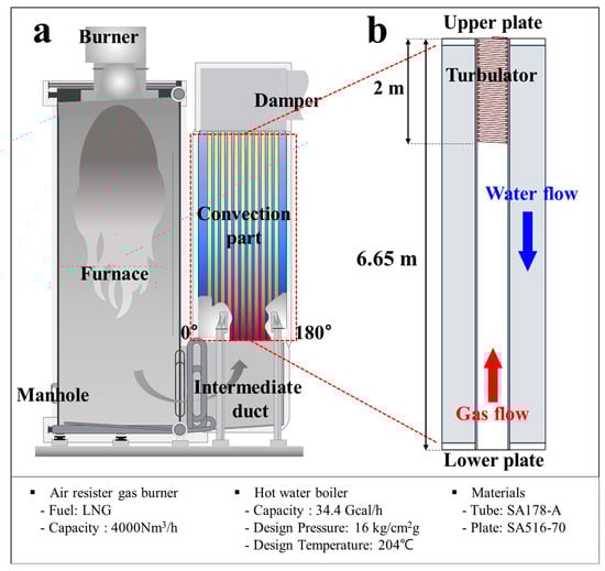
Figure 1.
Schematic diagram of (a) the peak load boiler (PLB) and (b) a magnified view of the convection part.

Table 1.
Chemical composition of boiler materials used in the peak load boiler (PLB) (SA178-A for tubes, SA516-70 for plates).
Table 2.
Chemical composition of LNG used in the peak load boiler (PLB).
2.2. Non-Destructive Inspection
Due to the structural constraints of the PLB, direct sampling of damaged tubes was not feasible. Instead, an endoscopic inspection was conducted to assess the internal condition of the convection tubes and characterize gas-side corrosion damage (Figure 2). The inspection focused on regions surrounding pre-existing water leaks, which were predominantly concentrated at 90° relative to the manhole (defined as 0°). This selection was based on historical failure records and operational observations, which indicated a tendency for leakage events to occur in this direction. The affected areas were systematically examined as part of a progressive damage chain originating from the initial leak site. Additionally, leak-free tubes were selected from various locations within the convection section to ensure a reliable comparison with leaked tubes. To compare the internal condition of leak-free and leaked tubes, selections were made at symmetric positions relative to the leakage-prone 90° direction. Specifically, tubes were chosen at 270° to investigate whether similar corrosion patterns were developing on the opposite side. Each selected tube position was recorded using a row-column notation for precise identification (Figure 2).
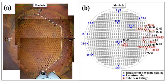
Figure 2.
(a) Photograph of the top of the convection section, illustrating tube arrangement and failure trend. (b) Schematic diagram of tube layout, leakage locations, and measurement points.
To examine the internal surface condition, a miniature camera was inserted through the lower end plate, capturing images as it ascended toward the upper section. The convection tube was divided into two distinct regions: the lower section (0–4.65 m from the lower end plate), which consisted solely of the tube structure, and the upper section (4.65–6 m), where a spiral turbulator was installed (Figure 1). Since the presence of the turbulator alters flow characteristics and heat transfer conditions, corrosion behavior was expected to vary between these regions. To further assess material loss due to corrosion, ultrasonic thickness measurements were conducted following the methodology described in []. This technique allowed for differentiation between internal (gas-side) and external (boiler water-side) corrosion, providing key insights into the dominant direction of corrosion propagation and the structural integrity of the convection tubes.
2.3. Corrosion Scale and Boiler Water Quality Analysis
To investigate the formation mechanisms of oxidation scales and their role in tube degradation, both solid-phase and solution-phase analyses were performed. Oxidation scales were collected from two distinct sources: (i) the inner surface of the PLB tubes and (ii) the surface of detachable turbulators removed from the convection section. The oxidation scales from the tube surfaces exhibited visually distinct colors, appearing as either white or red-brown deposits, suggesting differences in their chemical composition and formation conditions. To assess these variations, the white and red-brown scales were analyzed separately for structural and compositional differences. Additionally, oxidation scales from the turbulator surfaces were examined to determine whether their formation differed from those on tube surfaces.
X-ray diffraction (XRD) analysis using MDI Jade 5.0 software was conducted on both types of oxidation scales to determine their crystalline structures and phase compositions. However, XRD alone was insufficient to fully characterize localized elemental composition, particularly for micro-scale corrosion products. Therefore, energy-dispersive spectroscopy (EDS) was additionally employed to analyze fine-scale elemental distributions. Furthermore, cross-sectional scanning electron microscopy (SEM) was conducted to examine the morphology and internal structure of the oxidation scales, providing further insights into their formation and degradation behavior.
To further evaluate the chemical reactivity of the turbulator oxidation layer, a solution-phase analysis was performed to assess potential acidic species generated from the oxide layer. At least 1 g of oxidation scale was collected and dissolved in water for ion analysis using ion chromatography (IC) and inductively coupled plasma mass spectrometry (ICP-MS). This approach aimed to determine whether acidic species formed in solution could contribute to corrosion mechanisms within the PLB system.
In addition to the turbulator oxidation scale analysis, the chemical composition of the boiler feedwater was assessed over multiple sampling dates to evaluate its potential contribution to scale formation and corrosion. IC and ICP-MS were employed to quantify the concentration of dissolved ions and contaminants in the feedwater.
2.4. CFD Analysis of Gas Flow and Heat Transfer
To further assess the distribution of gas flow and temperature variations along the convection tubes, a computational fluid dynamics (CFD) simulation was performed using ANSYS 19.0. The primary objective was to identify regions with a high risk of corrosion damage by analyzing localized temperature gradients, flue gas behavior, and heat transfer efficiency.
The combustion system consists of an air resistor gas burner (Low NOx) with a fuel capacity of 4000 Nm3/h, ignited by an electric pilot igniter. Liquefied natural gas (LNG) is combusted in the furnace, generating high-temperature flue gases that enter the convection tube bundle from the lower end plate and rise toward the upper end plate. The initial gas temperature was set to 1160 °C, corresponding to the theoretical adiabatic flame temperature of LNG combustion. However, the actual flue gas temperature at the convection section inlet was determined based on operational data, reflecting real system conditions. The hot water boiler (PLB) is designed to withstand a maximum operating pressure of 16 kg/cm2g and a temperature of 204 °C, ensuring safe operation under these conditions. The simulation conditions included a flow rate of 50,206 Nm3/h (standard cubic meters per hour, based on operational data). The boiler feedwater supplied to the convection section was maintained at 65 °C and 0.88 MPa, with a mass flow rate of 625,455 kg/h (173.74 kg/s).
Steady-state simulations were performed, assuming that it was in operation and there was no heat released outside the boiler and the burner completely burned the LNG. The k-ε turbulence model was applied, and it was repeatedly calculated until the residual fraction of each variable fell to 10−5 or less to judge the convergence of the simulation analysis.
3. Results
3.1. Corrosion Damage Analysis
Figure 3 shows images of endoscopic analysis on the leak-free tubes shown in Figure 2. No surface defects (pits, cracks, etc.) were found inside the tube, and the turbulator mounted on the top was also intact. Figure 4 shows images of endoscopic analysis on the leaked tubes shown in Figure 2. An oxide scale was observed on the inner surface of the leaked tube exhibiting an uneven surface. The more severe oxides were formed in the section where the turbulator was installed. During the overhaul, the turbulator of the tube 20-37 was removed, and the surface of the tube under turbulator was observed. It was confirmed that pits were found on the surface of the tube in a form of a spiral corresponding to the location where the turbulator was in direct contact.
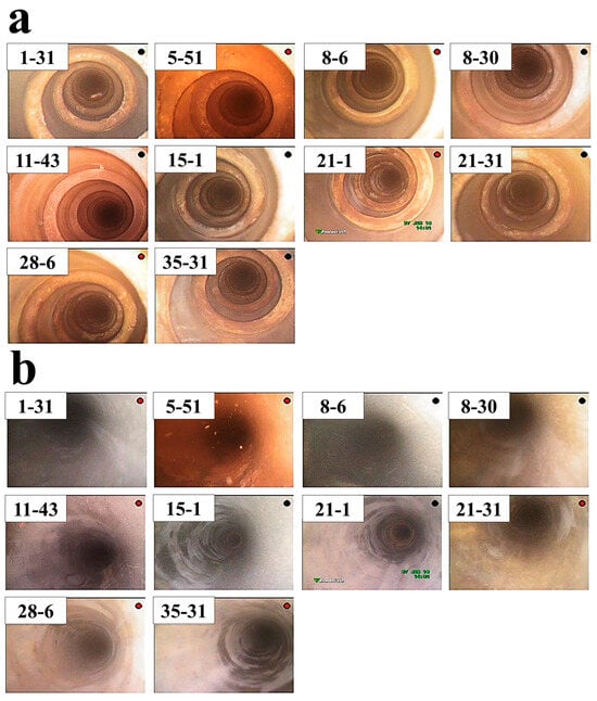
Figure 3.
Endoscopic image of selected representative tubes (non-leakage) of the lower end plate (shown in Figure 2); (a) the location where a turbulator is mounted, (b) inside the tube without the turbulator.
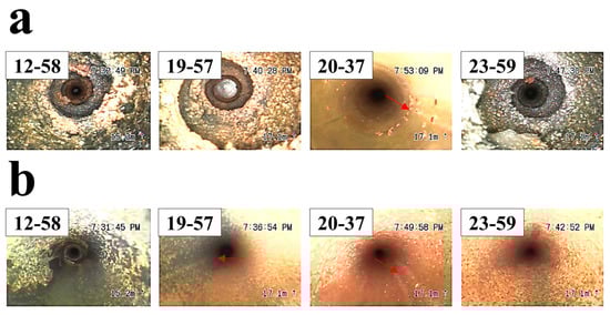
Figure 4.
Endoscopic image inside the leaked tubes located in the 90° direction of the lower end plate based on the manhole (0°) (shown in Figure 2); (a) the location where a turbulator is mounted, (b) inside the tube without the turbulator.
Figure 5 shows images of endoscopic analysis on the tube (without leakage) located nearby the leaked tube shown in Figure 2. It was observed that a large amount of oxide was present inside the tube. Although the oxide was found on the tube, breakage did not occur. The singularity was that corrosion product with a white-colored oxide occurred in a straight line in tube 24-58. It is thought of as the straight seam line of the tube manufactured by the electric resistance welding (ERW) method. It is known that internal defects produced by heat treatment and residual stress are the main reason for pitting corrosion, stress corrosion cracking, and grooving corrosion in the location of the seam of steel pipes fabricated by the ERW method [,,]. In addition, tubes manufactured using the ERW process have been reported to exhibit an increased susceptibility to corrosion along the weld seam [,,], which has a similar trend with our work. Figure 6 shows an ultrasound examination results to evaluate a reduction in tube thickness. The ultrasound results support that the tube is thinned along the axial direction of the seam line on the gas side []. The use of ERW tubes in this application raises concerns about material suitability. In high-temperature environments with frequent thermal cycling, seamless (SMLS) tubes are generally preferred due to their better resistance to thermal fatigue and corrosion. The observed corrosion along the weld seam suggests that the material choice may have played a role in the degradation process. This highlights the need for a more thorough evaluation of material selection criteria, particularly for components exposed to cyclic temperature variations in PLB systems.
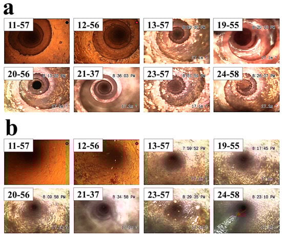
Figure 5.
Endoscopic image of tubes located nearby the leaked tubes shown in Figure 2; (a) the location where a turbulator is mounted, (b) inside the tube without the turbulator.
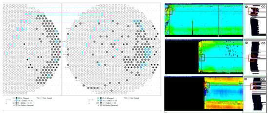
Figure 6.
Ultrasound test results of the convection tube, showing a thinning in the tube thickness [].
3.2. Corrosion Product and Element Analysis
Figure 7 shows the XRD analysis results for corrosion products. Two visually distinct white and red-brown oxides were examined. The white colored oxide was mainly formed on the tube seam and was found on a lower end plate partially. On the other hand, the red-brown colored oxide was mainly formed on the inside of the convection tube and lower end plate. It was found that the white-colored salt was sodium compounds such as NaNO3, NaCl, and Na2SO4 (Figure 7a), whereas the reddish-brown oxide scale exhibits the formation of iron oxides such as Fe3O4, Fe2O3, and FeOOH (Figure 7b). Table 2 shows the IC and ICP analysis results of water quality collected eight times during 11 months. The Na+ and Cl− components were the most contained, followed by the NO3− and SO42− components. Na+, Cl−, NO3− and SO42− have been detected in solution because of the addition of sodium compounds (NaOH, NaCl, Na2SO4) and oxygen scavenger (CH6N4O, C2H7NO). The components (Na, Cl, N) which do not existed in the material component are mainly from boiler water and LNG (Table 2 and Table 3). The sodium compound detected from the internal scale analysis does not form under a dry combustion gas environment. Additionally, sodium compound detected from the XRD analysis does not form under the LNG environment that consists of carbon dioxide and small amounts of nitrogen. Therefore, the sodium compound as a corrosion product results from the fact that boiler water was mixed with the gas. It is concluded that the boiler water vaporized by a leakage flows into the tube, forming a corrosion product on the inner surface of the tube.
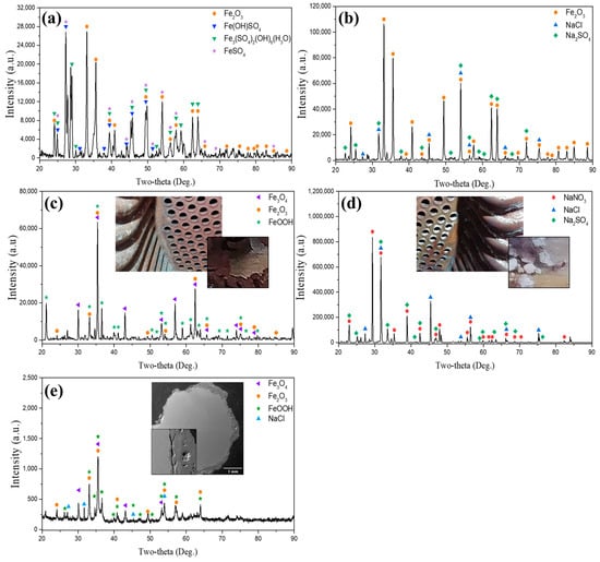
Figure 7.
XRD analysis of internal oxide scales collected from tubes at varying conditions within the convection section of the PLB. (a) Oxide scale from the inner surface of a failed tube in the leakage direction, (b) Oxide scale from an intact tube adjacent to the leakage site, (c) Oxide scale from an intact tube distant from the leakage site, (d) White-colored salt from an intact tube adjacent to the leakage site, (e) Oxide scale from the surface of the turbulator.
Table 3.
IC/ICP analysis of trace elements in turbulator oxide scales dissolved in solution.
The presence of these oxides indicates a heterogeneous chemical environment, where sodium compounds, originating from boiler water, contribute to a localized corrosion due to their hygroscopic and reactive nature. Meanwhile, the formation of iron oxides such as Fe3O4 provides temporary passivation, whereas Fe2O3 and FeOOH, typically associated with further oxidation states, signify progressive corrosion under moist conditions. This layered composition of corrosion products exacerbates the corrosion process by promoting uneven surface roughness, increased ionic conductivity, and localized electrochemical activity, thereby accelerating material degradation. These findings align with prior studies that highlight the role of mixed-phase oxides in intensifying corrosion susceptibility under environmental and operational conditions [,,,,,].
Figure 7 presents the XRD analysis results of oxide scales collected from different tube locations within the convection section of the PLB. Two visually distinct corrosion products were identified: red-brown oxides, predominantly composed of iron oxides, and white oxides, which primarily contained sodium-based compounds.
The red-brown oxide scales were mainly observed on the inner surfaces of both failed and intact tubes (Figure 7a–c). XRD analysis revealed the presence of Fe3O4, Fe2O3, and FeOOH, which are common iron oxides formed under varying oxidation conditions in humid environments. These oxides form sequentially through oxidation and dehydration reactions: 2Fe(OH)3 → 2FeOOH + H2O → Fe2O3 + Fe2+ +2H+ → Fe3O4 + H2O. The transition from FeOOH to Fe2O3 indicates further oxidation, while Fe3O4 formation suggests partial reduction processes under fluctuating oxidation states. The formation of Fe3O4 suggests the presence of an initial protective layer, while Fe2O3 and FeOOH indicates progressive oxidation and material degradation, as these phases typically form under prolonged exposure to moisture and an oxidizing environment. Notably, in the intact tube adjacent to the leakage site (Figure 7b), NaCl and Na2SO4 were detected alongside iron oxides, suggesting that these sodium-based compounds were introduced through the infiltration of boiler water and subsequently deposited on the tube surface. The white salt, primarily detected in tubes near leakage sites and on the turbulator surface, consisted of NaNO3, NaCl, and Na2SO4 (Figure 7d,e). The segregation of white oxide deposits (Figure 7d) confirmed that the major components of these were sodium compounds, further supporting the hypothesis that boiler water ingress and subsequent evaporation led to the formation of corrosive deposits. Additionally, the turbulator surface exhibited a combination of Fe-based oxides and NaCl (Figure 7e), suggesting that it was subjected to both high-temperature flue gas exposure and condensate deposition. Given its structural design, the turbulator provides surfaces where moisture can accumulate, making it more susceptible to localized cooling and corrosion.
Figure 8 compares the turbulator conditions in intact and near-leak regions. The intact turbulator (Figure 8a–c) retained its original shape, and its cross-section maintained a uniform, circular structure with minimal oxide formation. In contrast, the turbulator near the leakage site (Figure 8d–f) exhibited significant degradation, with a deformed shape and thick oxide layers covering its surface. The cross-sectional SEM image of the degraded turbulator revealed extensive oxidation, further confirming its exposure to an aggressive environment. XRD analysis of the turbulator’s surface oxide (Figure 7e) identified Fe-based oxides and NaCl, but did not reveal other minor elements. To evaluate trace components, over 1 g of turbulator surface oxide was collected and dissolved for solution-phase analysis using IC/ICP-MS (Table 3). The analysis detected Cl−, NO3−, SO42−, and Na+, with SO42− reaching 255 ppm, indicating a highly acidic environment that likely accelerated corrosion. The absence of SO42− in the XRD results suggests that sulfate concentrations were below the detection limit in solid-state analysis but became detectable in solution.
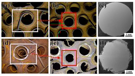
Figure 8.
Comparison of non-leaked and near-leak turbulator shapes in the convection section of the PLB. (a,b) Non-leaked turbulator and its corresponding upper plate surface, (c) SEM image of the turbulator cross-section in the non-leaked region (270°), (d,e) Near-leak turbulator and its corresponding upper plate surface, (f) SEM image of the turbulator cross-section in the near-leak region (90°).
Table 4 summarizes the water quality analysis of the boiler feedwater, revealing the presence of SO42−, Cl−, NO3−, and PO43−, which correlate with the ionic species identified in the system. The detection of these ions in the boiler feedwater analysis strongly suggests that water treatment chemicals played a significant role in the composition of leaked water. This confirms that boiler water leakage led to the reintroduction of these aggressive ions into the system, contributing to continued material degradation. The detected ionic species primarily originate from boiler water treatment chemicals used for pH control, scale inhibition, and corrosion prevention. Sulfate (SO42−) is commonly introduced through sodium sulfate (Na2SO4), which is used in water treatment to regulate pH and minimize scale formation. Chloride (Cl−) can result from sodium chloride (NaCl), which may be added for water softening or introduced as an impurity. Nitrate (NO3−) is often associated with oxygen scavengers or nitrate-based corrosion inhibitors, while phosphate (PO43−) is typically added as a scale inhibitor [,,].
Table 4.
IC and ICP analysis results of boiler feedwater collected eight times during 11 months.
These findings align with prior studies that highlight the role of mixed-phase oxides in intensifying corrosion susceptibility under environmental and operational conditions [,], further supporting the conclusion that boiler water leakage introduced corrosive ionic species into the convection section, leading to sodium salt deposition, acidification, and localized corrosion. Given that acidic condensation is a critical factor in corrosion acceleration, it is essential to determine whether operating conditions within the convection section facilitate dew point formation. To further investigate this aspect, computational fluid dynamics (CFD) simulations were conducted to evaluate the thermal distribution within the tubes and assess whether localized cooling effects could lead to dew point condensation and subsequent corrosion initiation.
3.3. Simulation on Gas Temperature Distribution
The CFD simulation was conducted under the most severe operating conditions, corresponding to the design pressure and design temperature of the PLB. In practice, the boiler typically operates under less extreme conditions; however, selecting these parameters ensures that the analysis encompasses worst-case scenarios where degradation is most likely to occur. A key challenge in evaluating the internal thermal environment is the lack of direct temperature measurements within the convection section. The only available temperature data are from stack emissions, which does not provide insight into localized temperature distributions inside the tubes. This limitation necessitated a numerical approach to estimate thermal gradients, gas flow behavior, and heat transfer characteristics within the system. While the simulation was performed under specific conditions, the results provide a basis for understanding the thermal environment and identifying areas prone to potential degradation.
Figure 9 presents the simulation results, showing a generally symmetrical temperature distribution across the lower plate. However, a slight temperature deviation was observed near 0°, where the gas exhibited a lower temperature compared to other regions, with a reduction of approximately 200 K. This was likely due to inertial effects, as the combustion gas shifted toward 180° while entering the convection section. Despite the lower temperature at 0°, leakage did not occur in this region due to the flow dynamics preventing boiler water intrusion. This indicates that the occurrence of leakage is more influenced by the transport dynamics of the leaked boiler water rather than solely by the local temperature distribution. The affected tubes near 90° experienced a higher degree of exposure to vaporized water due to gas flow patterns, leading to more significant condensate formation and corrosion progression in this area. Figure 9b illustrates the temperature variation from the center to the wall (edge) direction. The temperature gradually decreased toward the boiler wall due to reduced gas introduction inside the plumbing located on the wall. Due to symmetry, a similar result was obtained at 90° and 270°, confirming that regions near the boiler walls experienced lower temperatures compared to the central area.
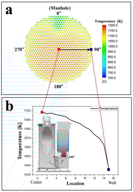
Figure 9.
Simulated temperature distribution of the combustion gas entering into the lower end plate of the convection tube, (a) temperature distribution of the inlet flowing into the convection tube, and (b) temperature variation from center to wall (edge) direction.
Figure 10 illustrates the temperature distribution of combustion gas along the tube height, comparing a tube located at the center with one near the boiler wall. The x-axis represents the inner diameter of the tube, while the y-axis denotes the gas temperature at different heights from the lower end plate. The simulation results indicate that, in both cases, the gas temperature decreases progressively as it ascends through the tube, reflecting heat exchange with the boiler water. A radial temperature gradient was observed, where the gas at the tube centerline remained at a higher temperature than the gas near the tube wall due to convective heat transfer effects. Comparing the two tube locations, the tube near the boiler wall exhibited consistently lower gas temperatures at equivalent heights compared to the centrally located tube. This difference is attributed to two main factors: (1) reduced gas inflow near the boiler wall, which limits the available thermal energy, and (2) enhanced heat dissipation due to increased heat transfer between the tube and the surrounding boiler water. These combined effects resulted in a more significant temperature drop near the wall region.
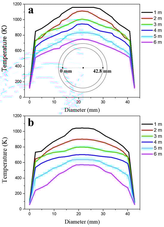
Figure 10.
Temperature change in the gas as a function of height from the lower end plate located (a) at the center and (b) at the wall of the lower plate (Figure 8b). X-axis denotes an inner diameter of tube.
Figure 11 shows how the gas temperature changes along the inner tube surface at different heights, comparing the center and wall-side tubes. The temperature of both tubes gradually decreases as the gas moves upward. However, the wall-side tube consistently exhibits lower temperatures than the center tube, with a temperature difference of 70 °C (343 K) at a height of 6 m from the lower end plate. The temperature drop is particularly pronounced at 4 m, where the turbulator is installed. Notably, in this region, the wall-side tube temperature falls below 60 °C (333 K).
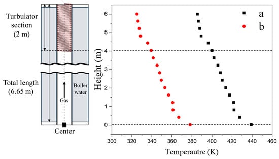
Figure 11.
Temperature variation in the gas as a function of height at the surface (0 or 42.8 mm, Figure 9a) of the convection tube in the locations of (a) center and (b) wall (edge).
This temperature difference is likely influenced by the proximity to the boiler water supply and the surrounding tube arrangement. The lower surface temperature of the wall-side tube suggests a higher likelihood of condensation, as moisture in the air can accumulate on surfaces below 100 °C (373 K). Additionally, the presence of acidic ions such as NO3−, Cl−, and SO42− can further promote dew formation even at elevated temperatures, as described by the following equations [,]. The partial pressure of moisture, chloride, and acid ions directly affects the dew point temperature [,,,,].
where Td is dew point temperature, PH2O is the partial pressure of water vapor, PSO3 is sulfur trioxide, PSO2 is sulfur dioxide, PHNO3 is nitric acid. Dew containing acid ions creates an acidic environment on the surface of tube and causes corrosion of carbon steel. Irregular operating conditions of the PLB cause the accumulation of acid ions and create a stronger acidic environment, thus accelerating the corrosion of carbon steel tubes leading to corrosion failure.
1000/(Td + 273.15) = {2.9882 − 0.1376 × ln(PH2O) − 0.2674 × ln(PSO3) + 0.03287 × ln(PH2O × PSO3)}
1000/(Td + 273.15) = {3.9526 − 0.1863 × ln(PH2O) + 0.000867 × ln(PSO2) − 0.00091 × ln(PH2O × PSO2)}
1000/(Td + 273.15) = {3.6614 − 0.1446 × ln(PH2O) − 0.0827 × ln(PHNO3) + 0.00756 × ln(PH2O × PHNO3)}
These structural features can create preferential sites for corrosion initiation, as supported by prior studies indicating that confined geometries exacerbate localized corrosion due to ion concentration effects [,]. Given that the turbulator is designed to enhance heat transfer, its role in influencing the local thermal and chemical environment must be further examined. The following section discusses the underlying corrosion mechanisms in detail, correlating these findings with experimental observations and numerical analyses.
3.4. Corrosion Failure Mechanisms
Figure 12 illustrates the progressive failure mechanism of dew point corrosion in peripheral tubes within the convection section of the PLB. This process is driven by a combination of thermal gradients, phase transitions, and ionic interactions, leading to localized corrosion and eventual tube failure. As corrosive species accumulate, the affected region expands, increasing the risk of secondary failures.
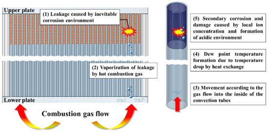
Figure 12.
Corrosion and failure mechanism of the PLB.
- (1)
- Primary corrosion and initial leakage occur as carbon steel tubes in the convection section are continuously exposed to high-temperature flue gas and boiler water. Over prolonged operation, localized thinning and material degradation lead to the formation of primary leakage points, near the 90° position relative to the manhole in this study. The escaping boiler water mixes with the flue gas, initiating further degradation processes.
- (2)
- Once in contact with high-temperature flue gas (over vaporization temperature), the leaked boiler water undergoes rapid vaporization, creating a moisture-laden gas mixture that rises along the convection tube bundle following the direction of gas flow. Due to inertial effects, the vapor preferentially accumulates along specific flow paths, particularly near the turbulator region, where localized cooling enhances condensation. Compared to tubes located at the center of the plate, wall-side tubes are more susceptible to condensation and subsequent corrosion due to their lower surface temperatures and proximity to stagnant flow regions. These areas facilitate the accumulation of acidic ions such as Na+, Cl−, SO42−, and NO3−, leading to an increasingly aggressive corrosion environment.
- (3)
- As the vaporized water travels through the convection tubes, the gas temperature decreases due to heat exchange with the boiler water inside the tubes. When the local temperature reaches the dew point, condensation occurs. The turbulator region is particularly vulnerable to condensation due to localized temperature drops and flow disturbances induced by its structural features. Since the dew point temperature is influenced by the partial pressure of acidic ions, areas with higher ion concentrations experience condensation at higher temperatures. Under typical flue gas conditions, dew formation generally occurs below 100 °C (373 K); however, as acidic species accumulate, condensation can occur at temperatures as high as 150–200 °C (423–473 K), significantly expanding the corrosion-prone region beyond the immediate vicinity of the leak.
- (4)
- The condensed water film on the turbulator surface traps corrosive ions such as Cl−, NO3−, and SO42−, which were identified in the water quality analysis. The morphological features of the turbulator, including grooves and surface depressions, enhance localized condensate retention, creating highly corrosive microenvironments. These ions originate from boiler water treatment chemicals and enter the system through leakage, leading to localized acidification and intensified electrochemical corrosion reactions. As acidic ion concentrations increase, the local pH drops, and the dew point continues to rise, allowing condensation to occur at even higher temperatures. This results in an expanding corrosion zone, with secondary failures appearing in adjacent tubes.
- (5)
- Since internal leakage cannot be immediately addressed during normal operation, corrosive species continue to accumulate over time. The prolonged presence of leaked boiler water, combined with repeated thermal cycles, accelerates acidification and localized corrosion, leading to widespread material degradation. Initially, failure is concentrated near the 90° position, where the first leakage occurs. Over time, the affected corrosion-prone zone expands, with secondary failures occurring at 0° and 180° due to the recirculating nature of the convection flow. As the acidic environment intensifies, new corrosion sites develop even in areas where the temperature was previously too high for condensation, demonstrating the self-propagating nature of dew point corrosion in this system.
This mechanistic analysis highlights how dew point corrosion in the PLB progresses beyond the initial leak site, driven by increasing ion concentration, rising dew point temperatures, and gas flow patterns. The turbulator’s structure further enhances localized condensation, leading to a persistent and expanding corrosion-prone zone, which cannot be addressed until scheduled maintenance or overhaul periods.
4. Conclusions
In the present study, the causes and mechanisms of corrosion failure of the peak load boiler have been investigated and analyzed through experiments and simulations. The followings are the main conclusions drawn:
- Severe localized corrosion and progressive leakage were observed near the turbulator in the leaking peripheral tube. Corrosion damage was particularly concentrated in the upper section near the turbulator, where accumulated corrosion products indicate sustained material degradation. Initially, corrosion was concentrated at 90° relative to the manhole, but as acidic condensation accumulated, degradation gradually propagated along the gas flow path.
- Water quality analysis and corrosion product characterization identified ammonium (NH4+), nitrate (NO3−), sulfate (SO42−), sodium (Na+), and chloride (Cl−) as key contributors to corrosion scale and salt formation. These ions primarily originated from combustion gas and vaporized boiler water, forming a highly acidic and chloride-rich electrolyte environment that significantly accelerates carbon steel corrosion.
- Computational fluid dynamics (CFD) simulations confirmed that vaporized boiler water entrained in the combustion gas could reach dew-forming temperature ranges along the tube wall. The upper section of the tube, where the turbulator is installed, exhibited lower gas temperatures, increasing the risk of acidic condensation. This temperature gradient promoted dew formation and localized acid accumulation, exacerbating corrosion.
- The corrosion mechanism is linked to the combined effect of water vapor condensation and gas flow dynamics. During operation, vaporized water from leaks mixes with the combustion gas and accumulates near the tube’s upper section. As the temperature drops below the dew point, strong acidic ions are formed and accumulated at this location, which accelerates corrosion process and leads to subsequent secondary failures.
Challenges in direct intervention during operation limit the ability to mitigate corrosion progression. Since internal leakage cannot be addressed until scheduled overhauls, corrosive species continue to accumulate, leading to widespread material degradation before maintenance can be performed. This highlights the necessity of proactive monitoring and preventive strategies to mitigate dew point corrosion in PLB systems. Implementing real-time monitoring techniques and optimizing boiler water chemistry management could significantly reduce corrosion risks and extend the operational lifespan of these systems.
Author Contributions
M.J.S., Writing—original draft, Investigation, Formal analysis; W.C.K., Methodology, Resources; S.Y.L., Writing—review and editing, Supervision, Funding acquisition. All authors have read and agreed to the published version of the manuscript.
Funding
This work was supported by the Korea District Heating Corporation and partially supported by a National Research Foundation (NRF) grant funded by the Korean government (RS-2024-00398068, RS-2023-NR077179).
Institutional Review Board Statement
Not applicable.
Informed Consent Statement
Not applicable.
Data Availability Statement
The original contributions presented in the study are included in the article, further inquiries can be directed to the corresponding author.
Acknowledgments
The authors would like to thank M. Hong, Y. Kim, and H. Chae for their help on experiments.
Conflicts of Interest
Author Woo Cheol Kim was employed by the company Korea District Heating Corp. The remaining authors declare that the research was conducted in the absence of any commercial or financial relationships that could be construed as a potential conflict of interest.
References
- Tsubakizaki, S.; Wada, T.; Iwato, T.; Nakahara, T.; Nakamoto, M.; Noguchi, Y. Advanced water treatment technologies (high-AVT) for HRSG corrosion control corresponding to new JIS B8223 (Japanese Industrial Standards). Mitsubishi Heavy Ind. Technol. Rev. 2017, 54, 63–68. [Google Scholar]
- Lee, K.; Han, H.; Shin, S.; Sung, K.; Rhee, Y. Analysis on Formation of Corrosion Products in Secondary Steam-Water System of Nuclear Power Plant. Corros. Sci. Technol. 2019, 18, 138–147. [Google Scholar]
- Lee, S.J. Analysis of Corrosion Resistance and Dew Point with Exhaust Gas Concentration and Temperature for Air Preheater Materials in Power Plants. Corros. Sci. Technol. 2023, 22, 351–358. [Google Scholar]
- Shin, J.; Kwon, H.J.; Kim, H.; Lee, D. Atmospheric Corrosion Model of Carbon Steel Considering Relative Humidity, Chloride Deposition Rate, and Surface Particles. Corros. Sci. Technol. 2024, 23, 324–333. [Google Scholar]
- Wasim, M.; Djukic, M.B. External corrosion of oil and gas pipelines: A review of failure mechanisms and predictive preventions. J. Nat. Gas Sci. Eng. 2022, 100, 104467. [Google Scholar] [CrossRef]
- Ebara, R.; Tanaka, F. Sulfuric acid dew point corrosion in waste heat boiler tube for copper smelting furnace. Eng. Fail. Anal. 2013, 33, 29–36. [Google Scholar] [CrossRef]
- Ding, Q.; Tang, X.; Yang, Z. Failure analysis on abnormal corrosion of economizer tubes in a waste heat boiler. Eng. Fail. Anal. 2017, 73, 129–138. [Google Scholar] [CrossRef]
- Zeng, Y.; Li, K.; Hughes, R.; Luo, J. Corrosion mechanisms and materials selection for the construction of flue gas component in advanced heat and power systems. Ind. Eng. Chem. Res. 2017, 56, 14141–14154. [Google Scholar] [CrossRef]
- Pal, U.; Kishore, K.; Mukhopadhyay, S.; Mukhopadhyay, G.; Bhattacharya, S. Failure analysis of boiler economizer tubes at power house. Eng. Fail. Anal. 2019, 104, 1203–1210. [Google Scholar] [CrossRef]
- Cho, S.; Kim, S.; Kim, W.; Kim, J. Stress corrosion cracking of heat exchanger tubes in district heating system. Corros. Sci. Technol. 2019, 18, 49–54. [Google Scholar]
- Kwon, J.K.; Ahn, D.H.; Jeong, D.H.; Kim, Y.J.; Woo, N.S.; Kim, S. Effects of pre-corrosion and cathodic protection in artificial seawater on S-N fatigue behavior of X80 steel. Korean J. Met. Mater. 2013, 52, 757–767. [Google Scholar]
- Wang, D.; Chen, L.; Zhao, Y.; Chen, W.; Wang, C.; Yan, J. Thermomechanical stress analysis and fatigue lifetime evaluation of coal-fired boiler components during peak shaving transient processes: Effects of load cycling rate. Int. J. Pres. Ves. Pip. 2023, 206, 105083. [Google Scholar] [CrossRef]
- Kim, Y.; Chae, H.; Hong, M.; Song, M.J.; Cho, J.; Kim, W.C.; Ha, T.B.; Lee, S.Y. Corrosion failure analysis of the convection part of district heating peak load boiler. Corros. Sci. Technol. 2019, 18, 55–60. [Google Scholar]
- Fazzini, P.G.; Otegui, J.L. Experimental determination of stress corrosion crack rates and service lives in a buried ERW pipeline. Int. J. Pres. Ves. Pip. 2007, 84, 739–748. [Google Scholar] [CrossRef]
- Luo, S.J.; Wang, R. Identification of the selective corrosion existing at the seam weld of electric resistance-welded pipes. Corros. Sci. 2014, 87, 517–520. [Google Scholar] [CrossRef]
- Mueller, R.A. Pitting and crevice corrosion in ERW carbon steel heat exchanger tubes. J. Mater. Energ. Syst. 1980, 2, 60–64. [Google Scholar] [CrossRef]
- Ritchie, P. The Susceptibility of Electric Resistance Welded Line Pipe to Selective Seam Weld Corrosion. Master’s Thesis, The Ohio State University, Columbus, OH, USA, 2020. [Google Scholar]
- Rahman, M.; Murugan, S.P.; Ji, C.; Cho, Y.J.; Cheon, J.Y.; Park, Y.D. Evaluation of Grooving Corrosion and Electrochemical Properties of H2S Containing Oil/Gas Transportation Pipes Manufactured by Electric Resistance Welding. Corros. Sci. Technol. 2018, 17, 109–115. [Google Scholar]
- Hu, Q.; Yang, S.; Zhang, W.; Da, G.; Xu, X.; Wang, X. Corrosion failure analysis of engineering structural steels in tropical marine atmospheres: A comparative study of ordinary and new weathering steels. Eng. Fail. Anal. 2024, 156, 107830. [Google Scholar] [CrossRef]
- Asami, K.; Kikuchi, M. In-depth distribution of rusts on a plain carbon steel and weathering steels exposed to coastal–industrial atmosphere for 17 years. Corros. Sci. 2003, 45, 2671–2688. [Google Scholar] [CrossRef]
- Misawa, T.; Asami, K.; Hashimoto, K.; Shimodaira, S. The mechanism of atmospheric rusting and the protective amorphous rust on low alloy steel. Corros. Sci. 1974, 14, 279–289. [Google Scholar] [CrossRef]
- Hong, M.; Cho, J.; Song, M.J.; Kim, W.C.; Ha, T.B.; Lee, S.Y. Corrosion behavior of boiler tube under circulation water conditions in district heating system. Corros. Sci. Technol. 2018, 17, 287–291. [Google Scholar]
- Kiang, Y. Predicting dew points of acid gases. Chem. Engin. 1981, 88, 127. [Google Scholar]
- McCoy, J.W. The Chemical Treatment of Boiler Water; Chemical Publishing Company: New York, NY, USA, 1981. [Google Scholar]
- Boffardi, B.P. Corrosion inhibitors in the water treatment industry. In Uhlig’s Corrosion Handbook, 3rd ed.; Revie, R.W., Ed.; John Wiley & Sons: Hoboken, NJ, USA, 2011; pp. 591–603. [Google Scholar]
- Panigrahi, B.S.; Ganapathysubramanian, K. Boiler Water Treatment. In Mineral Scales and Deposits; Amjad, Z., Demadis, K.D., Eds.; Elsevier: Amsterdam, The Netherlands, 2015; pp. 639–655. [Google Scholar]
- Verhoff, F.H.; Banchero, J.T. Predicting dew points of flue gases. J. Chem. Eng. Prog. 1974, 70, 71–72. [Google Scholar]
- Huijbregts, W.M.M.; Leferink, R. Latest advances in the understanding of acid dew point corrosion: Corrosion and stress corrosion cracking in combustion gas condensates. Anti-Corros. Methods Mater. 2004, 51, 173–188. [Google Scholar] [CrossRef]
Disclaimer/Publisher’s Note: The statements, opinions and data contained in all publications are solely those of the individual author(s) and contributor(s) and not of MDPI and/or the editor(s). MDPI and/or the editor(s) disclaim responsibility for any injury to people or property resulting from any ideas, methods, instructions or products referred to in the content. |
© 2025 by the authors. Licensee MDPI, Basel, Switzerland. This article is an open access article distributed under the terms and conditions of the Creative Commons Attribution (CC BY) license (https://creativecommons.org/licenses/by/4.0/).