Article

A Peak Absorption Filtering Method for Radiated EMI from a High-Speed PWM Fan

1
School of Mechanical and Electrical Engineering, University of Electronic Science and Technology of China, Chengdu 611731, China
2
AECC Aero Engine Control System Institute, Wuxi 214000, China
*
Author to whom correspondence should be addressed.
Appl. Sci. 2025, 15(8), 4568; https://doi.org/10.3390/app15084568
Submission received: 20 February 2025 / Revised: 12 April 2025 / Accepted: 18 April 2025 / Published: 21 April 2025
(This article belongs to the Special Issue Trends and Prospects in Applied Electromagnetics)

Abstract

:
Axial flow fans are widely used for heat dissipation in electronic devices. Due to its frequent speed-regulation to adapt to the change in heat load, a fan can cause significant electromagnetic radiation interference. In this study, a peak absorption filtering method is proposed to address the radiation interference issue in a high-speed PWM axial flow fan. The mechanism and coupling paths of radiation interference were analyzed, and a radiation interference calculation using finite integration technique by a hybrid field-circuit model and experimental measurement were conducted to identify the winding as the main source of radiation in PWM fan. Considering the limited space inside the fan, an integrated, non-inductive filtering circuit was designed to absorb the peak voltage entering the windings and the filter parameters are determined via circuit simulation. The measurement results indicate that the filtering method can reduce overall electromagnetic interference with a maximum peak reduction of 41.9 dB, without affecting the useful signals.

1. Introduction

Axial flow fans are extensively employed in electronic devices for thermal management due to their compact structure, high efficiency, and reliable airflow generation. A typical axial flow fan comprises three key components: a brushless DC (BLDC) motor, an impeller, and a fan frame, as illustrated in Figure 1. The impeller is directly coupled to the motor shaft, and when energized, the motor drives the impeller to rotate, producing an axial airflow that enhances convective heat dissipation within electronic enclosures.
To accommodate varying thermal loads under different operating conditions, axial flow fans often employ dynamic speed regulation. The most prevalent control method is pulse width modulation (PWM), which adjusts the motor’s rotational speed by modulating the duty cycle of the input voltage. While PWM ensures efficient thermal management, it introduces rapid switching transients in the motor windings, leading to abrupt changes in current and voltage. These high-frequency switching actions generate conducted and radiated electromagnetic interference (EMI), manifesting as distinct spectral peaks at specific harmonic frequencies [1,2,3,4], as evidenced by the measurement results in Figure 2.
The EMI emissions from BLDC motors pose a critical challenge in modern electronic systems, particularly in applications where electromagnetic compatibility (EMC) is strictly regulated. In industries such as aviation, aerospace, and medical electronics, even minor EMI disturbances can disrupt sensitive communication systems, navigation equipment, or diagnostic instruments [5,6]. Consequently, regulatory bodies have established stringent EMI limits for cooling fans and other electromechanical components. Additionally, standardized testing methodologies, including MIL-STD-461G, CISPR 25, and DO-160, have been developed to assess and mitigate EMI risks in critical environments. Given the increasing demand for high-performance and low-EMI cooling solutions, a thorough investigation into the generation mechanisms, propagation paths, and suppression techniques of motor-induced EMI is imperative. It is of great significance to study the mechanism of motor radiated interference and develop effective suppression methods.
At present, research mainly focuses on the mechanism of conducted interference, focusing on the modeling and suppression of conducted interference in electrical machines. Conducted interference models for switch devices were established in [7], and a numerical model of a power transfer system was developed and used in simulation [8]. The conducted interference of a motor drive system was analyzed and modeled in [9,10,11]. The EMI suppression method of the DC motor was studied in [12,13] to attenuate both common-mode (CM) and differential-mode (DM) interference.
Research on radiated interference has mostly focused on modeling and predicting the radiated interference from components in power systems [14,15]. Ref. [16] presents an equivalent modeling method for the electromagnetic radiation of PWM fan. Many publications analyzing EMI sources and propagation provide a better understanding of the EMI generation mechanism [17,18,19]. For suppression of radiated interference, the main methods include changing the PWM control strategy and optimizing the system structure [20,21,22,23]. The design process of the methods above is complex due to the redesign of the system structure.
Designing EMI filters is an effective approach to mitigate radiated interference. Chuang C [24] designed the filter to attenuate both conducted and radiated interference. And the installation location and topology of the filter are also a problem worth investigating. The prevalent filter topologies often incorporate inductive components, leading to bulky filter designs that are not suitable for small-sized axial flow fans.
Therefore, this paper focuses on the radiated interference exceeding the standard of a small axial flow fan. The generation mechanism of the radiated interference and the coupling path were analyzed based on the principle of PWM motor speed control. The main radiation source of the fan was clarified through the calculation of the radiated interference model by the finite integration technique (FIT) [25]. Taking into consideration the spatial structure of the fan and the frequency characteristics of the interference, a non-inductive filter circuit was designed. The measurement results showed that the filter circuit can effectively suppress the radiated interference without increasing the effective signal insertion loss and meet the standard limit requirements.

2. Circuits Structure and Radiated EMI Measurement

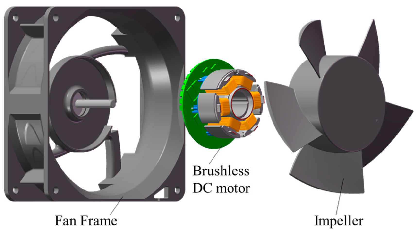
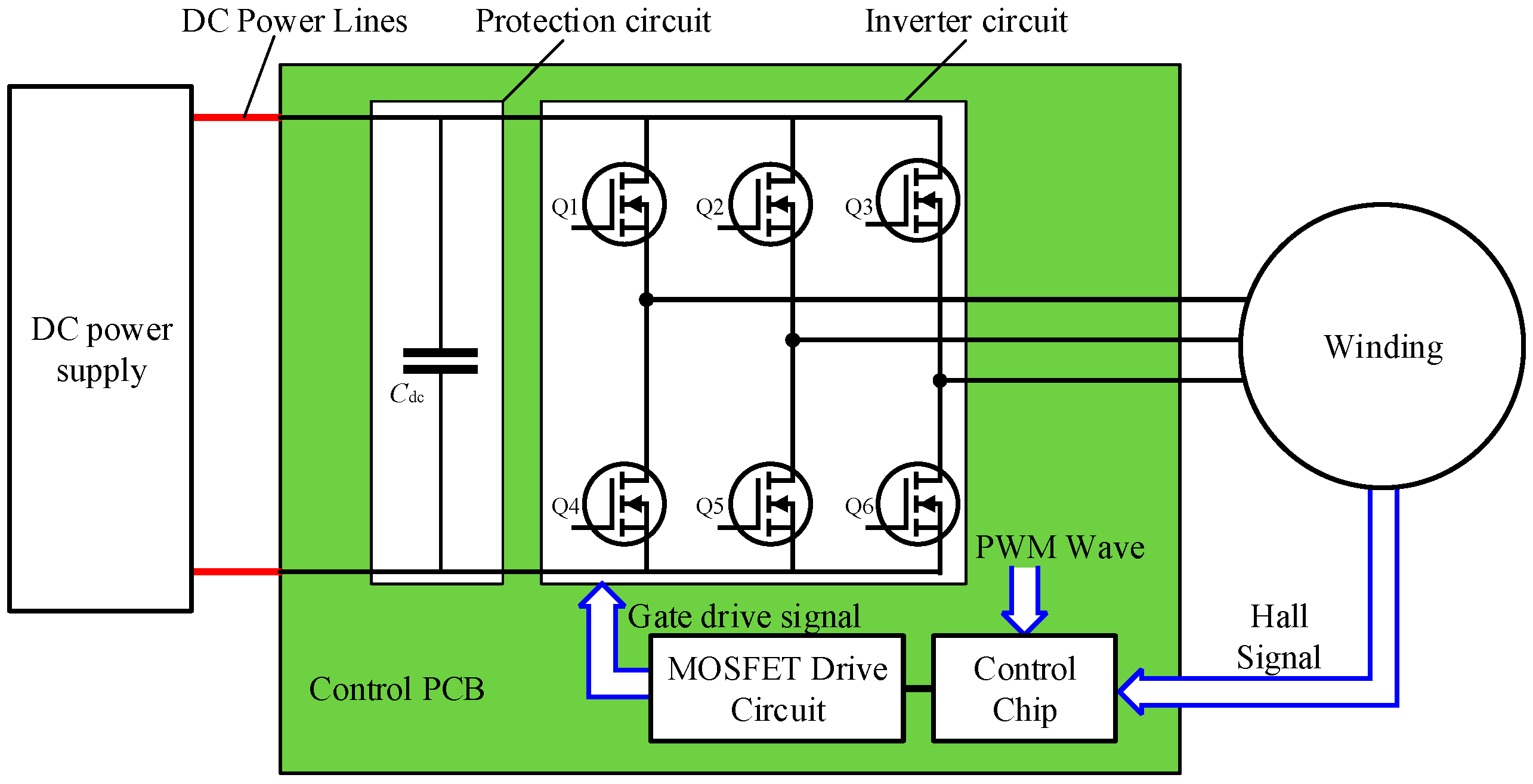
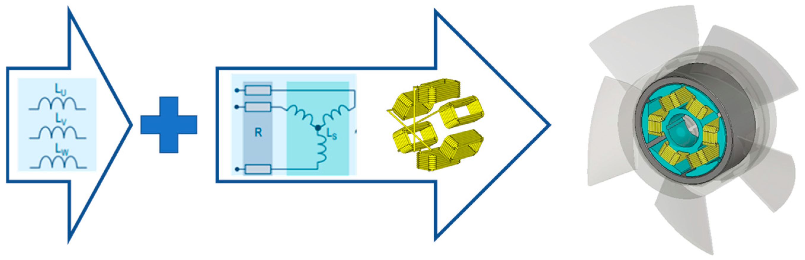
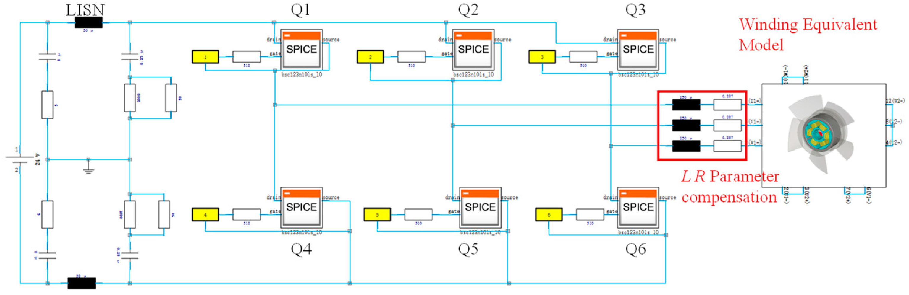
2.1. Drive Circuit Structure and Speed Control Strategy

The axial flow fan is driven by a PWM permanent magnet brushless DC motor. The drive circuit mainly consists of a control chip, a MOSFET drive circuit, an inverter circuit, a protection circuit, and a winding coil, as shown in Figure 3.
The inverter circuit adopts a three-phase half-bridge inverter topology consisting of six power MOSFETs. The control chip outputs a gate drive signal by recognizing the duty cycle of the modulated square wave to control the switching of the MOSFETs, thus changing the winding terminal voltage to adjust the motor speed. In this paper, the fan adopted the HPWM-LON modulation mode, i.e., the power MOSFETs in the upper bridge arm were controlled by the PWM signal, while the MOSFETs in the lower bridge arm were continuously conducting within one cycle of phase alternation. The modulation frequency was 15.5 kHz. Figure 4 shows the waveforms of each bridge arm drive signal in the time domain during the modulation process. Q1, Q2, and Q3 are the drive signals for MOSFET in the upper bridge arm, and Q4, Q5, and Q6 are the drive signals for the ones in the lower bridge arm.

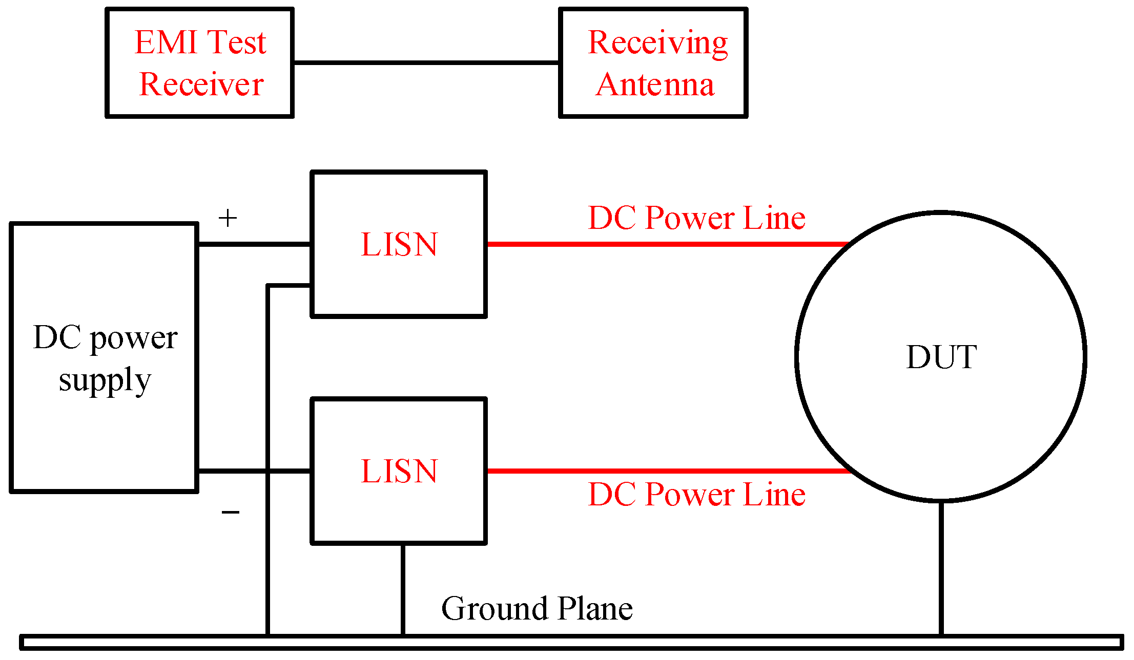
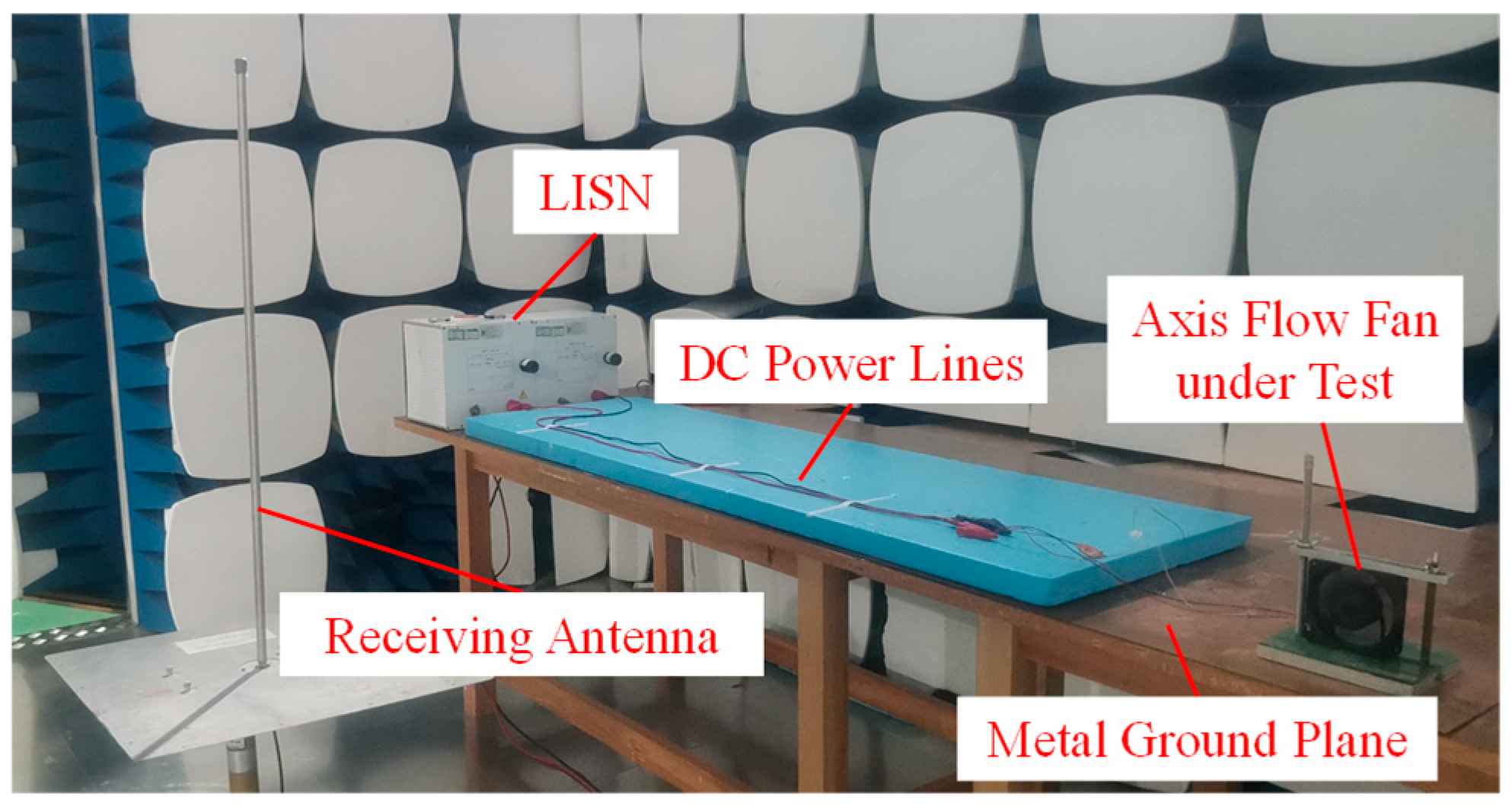
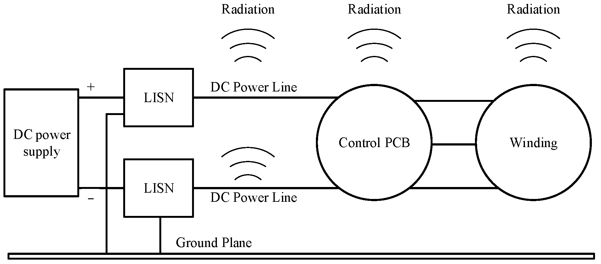
2.2. Radiated EMI Measurement and Analysis of Results

According to MIL-STD-461G, the radiated emission measurement configuration of the fan was as is shown in Figure 5. The measurement layout consisted of a DC power supply, two DC line impedance stabilization networks (LISN), two power lines, a receiver antenna, an EMI receiver, and the fan under test. The measurement environment was a shielded dark room, and the receiving antenna was placed 1 m away from the device under test, as shown in Figure 6. Within the rated operating range of the fan, the EMI receiver antenna measured the amplitude of the electric field in the frequency range of 10 kHz–30 MHz.
The measurement procedures were as follows:
a. Ambient Condition Check: Confirm that the environmental conditions comply with the specified standards to prevent any impact on test accuracy.
b. Equipment Initialization: Power on the measurement instruments and allow adequate stabilization time.
c. Device Preparation: Switch on the test equipment and ensure it stabilizes properly before proceeding.
d. Emission Assessment: Following the configuration in Figure 5, measure the radiated emissions from the test device and its connected cables.
The fan under test had a rated voltage of 24 V, a rated power of 103.8 W, a peak speed of 10,500 rpm, and a pole pair number of 2. Under the PWM condition, the results of the electric field radiation measurement on the fan were as shown in Figure 7. At the frequency of 15.5 kHz, the intensity of the radiated electric field measured was 72.41 dBμV/m, which was higher than the limit value of 57.02 dBμV/m required by the standard. According to the measurement results, it can be seen that there were a number of peaks of interference exceeding the standard limits in the measurement band at a series of peaks with a fundamental frequency of 15.5 kHz, which is consistent with the modulation frequency of the PWM, indicating that these frequency peaks were indeed caused by the switching of the MOSFETs in the inverter circuit with their frequency harmonics.

3. Mechanism of Fan Radiation and Analysis of Radiated Source

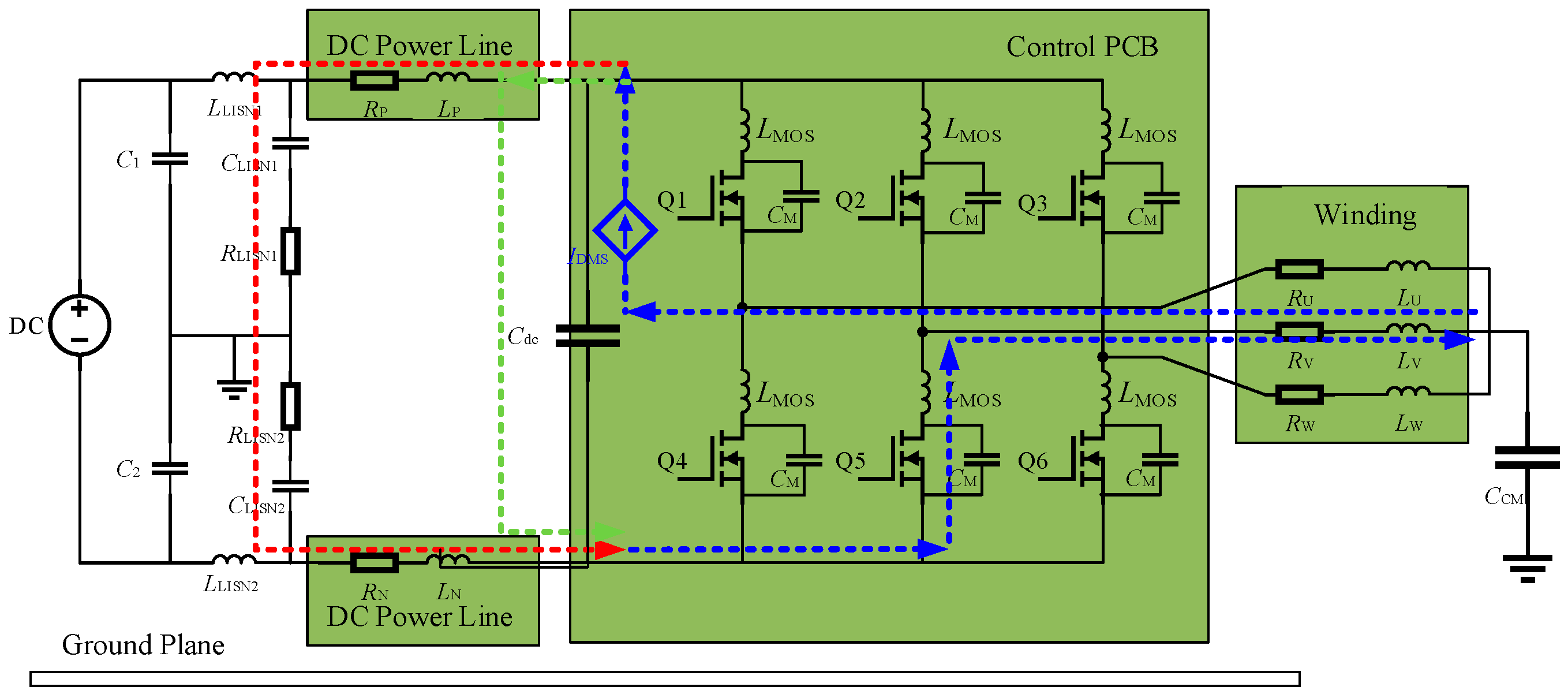
3.1. Generation Mechanism and Path Analysis of Conducted Interference

In EMC design, the three elements of interference sources, propagation paths, and sensitive equipment are included. Radiated interference is generated externally by conducted interference in circuits through components with an antenna effect. The generation of conducted interference in the fan is closely related to the high-speed on/off characteristics of power MOSFETs. Assuming that the amplitude of the PWM wave is U, the period is T, the rising and falling edge times are t, and the turn-on time of the switching device in one cycle is ton, the duty cycle can be expressed as
d = t on / T
According to the Fourier transform, the amplitude-frequency characteristics of the interference source can be obtained:
V f = 2 d U sin n π d n π d sin π t f π t f
where n is the harmonic number. According to Equation (2), the PWM signal contains many high harmonics in addition to the fundamental waveform for normal operation, and these harmonics propagate through the conduction path to other components.
The conducted paths of EMI can be divided into common mode conducted paths and differential mode conducted paths. Each time a switching action occurs, the voltage at the midpoint of the bridge arm relative to the negative line of the power supply changes rapidly, thus generating common mode interference; at the same time, the switching process of the switching device also causes a sharp change in the current of the bridge arm, resulting in differential mode interference.
The common mode interference conduction path is shown as the red dashed line in Figure 8. Common mode interference is generated by transient voltage trips during switching dynamics, and the resulting current to ground forms a closed loop through the windings, ground, and DC line.
The differential mode interference conduction path is shown by the dotted line in Figure 9.
Path 1: Assuming that the switching state is that Q1 and Q5 are open, the differential mode current flows into the DC side from the U phase; flows through the DC cable, LISN, and flows out from the V phase; and finally passes through the winding, forming a closed loop.
Path 2: Differential mode current flows from the U phase into Cdc and out from the V phase, and it finally passes through the winding, forming a closed loop.
In the conducted path of electromagnetic interference, the DC power lines, windings, and PCB have antenna effects and can be highly efficient sources of electromagnetic radiation, and the interference current will radiate energy outward through these pathways, as shown in Figure 10. Therefore, before investigating the suppression methods of radiated interference, the intensity of radiated interference from the components in the loop needs to be further analyzed to target the proposed interference suppression methods.

3.2. Analysis of Radiated Interference from DC Power Lines

To analyze the electric field radiation intensity of the DC line, the UL1332 20# power lines without shielding layer were replaced by a double shielded line of RG316D, and the shielding layer was well grounded. The results of the radiated emission measurement are shown in Figure 11. There was no significant decrease in the amplitude of the peak field in the tested frequency band, which indicates that shielding the DC cables did not reduce the system radiated interference, i.e., for lower frequency bands, the DC power lines were not the main source of radiation for the axial flow fan.

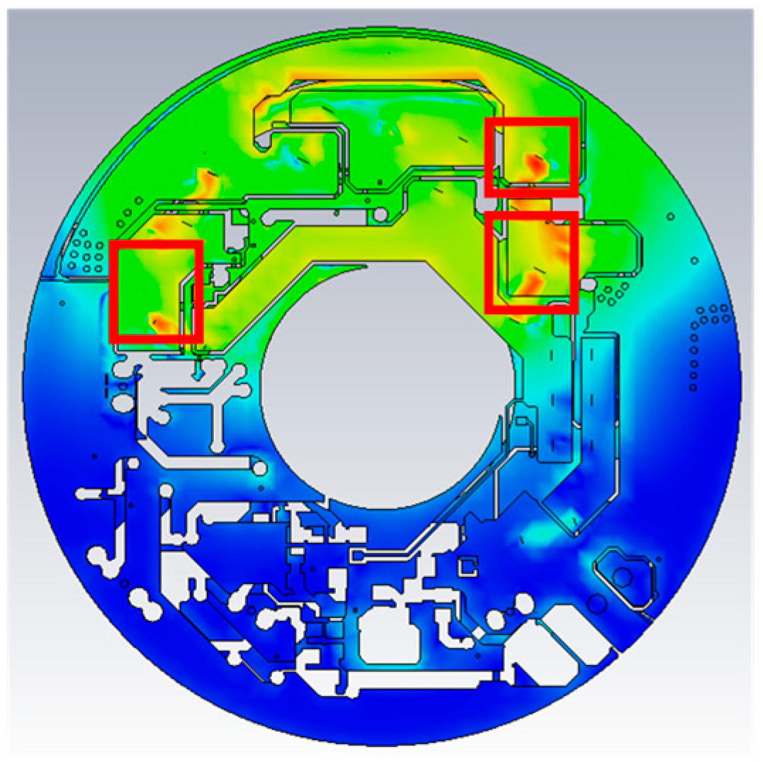
3.3. Analysis of Radiated Interference from Winding and Control PCB

The windings and PCB were integrated inside the axial flow fan, and it was impractical to experimentally measure their radiation intensity separately. Hence, the radiated interference from the winding and control PCB was modeled, calculated, and analyzed by finite integration technique in the time domain, respectively.
According to the finite integral theory, the Maxwell mesh equation was obtained as
C e = d d t b , C ˜ h = i C + i S + d d t d
where C and C ˜ are the discrete curl matrices of the main grid and the dual grid, e is the voltage along the edge, and b is the magnetic flux through the face elements in the main grid. h is the magnetic field along the edge of the dual grid. d , i C , and i S are the electric flux, loss current, and external current, respectively.
Using the central difference discretization as well as the frog-leaping scheme for the time derivative terms of the two spinodal equations in the above equation, the explicit time-domain recursive equation of the finite integration method is given by
e n + 1 = C A E e n + C A H C ˜ h n + 1 2 i S n + 1 2 h n + 1 2 = h n 1 2 Δ t D μ 1 C e n
where
C A E = D ε Δ t + D σ 2 1 D ε Δ t D σ 2 C A H = D ε Δ t + D σ 2 1
where Dε, Dσ and Dμ are the permittivity matrix, electrical conductivity matrix, and magnetic reluctivity matrix, respectively. The transient electromagnetic process of the winding and PCB can be calculated according to Equations (4) and (5) by CST Studio Suite. To achieve field-circuit coupling, the excitation current is represented by adding the current i L to the right side of Ampere’s law, i.e.,
C ˜ h n + 1 2 = D σ e n + 1 + e n 2 + D ε e n + 1 e n Δ t + i L n + 1 2
The field-circuit coupled transient process can be calculated according to (6).
The axial flow fan has a winding structure with a three-phase star structure and six slots. To assess the radiated interference of the winding, this paper employed a hybrid modeling approach that integrated field and circuit elements. Specifically, during the winding modeling process, 3D modeling was conducted based on the actual winding layout. The R and L parameters of the winding were then compensated using a circuit model, as illustrated in Figure 12. As CST’s computational algorithms have difficulty in precisely modeling the influence of magnetic poles on winding parameters, we intentionally omitted the material properties of this component during the 3D modeling phase. Consequently, parameter compensation was applied in the circuit domain with R = 0.287 Ω and L = 250 μH according to reference [16]. This approach not only aligns with the actual 3D layout of the winding but also ensures that the circuit parameters of the winding meet the requirements.
The stator winding was fabricated using 0.71 mm diameter enamel-coated copper wire, with each slot containing 25 precisely wound turns. The 3D modeling process was carried out in SolidWorks 2021, which included detailed representations of the stator slots, coil windings, and permanent magnet components. For the electrical connections, a star-type arrangement was implemented for the three-phase winding system, with the completed 3D winding assembly illustrated in Figure 12. The magnetic circuit incorporated high-performance NdFeB permanent magnets, while the core structure was assembled from stacked silicon steel laminations to optimize magnetic effects. The components in the circuit were linked to the field model through an external circuit, where the FIT method in the time domain with field-circuit coupling was employed for a numerical solution. The full-wave field-circuit simulation model of the winding and inverter circuit was established in CST, as shown in Figure 13.
The control PCB was then imported into CST Microwave Studio in ODB++ format. The winding port Touchstone model obtained through parameter extraction was imported into CST Design Studio as a circuit block to establish the field-circuit radiation simulation model of the PCB and the inverter circuit, as shown in Figure 14.
The influence of the fan frame and fan impeller on the radiation of the internal winding and PCB was also not negligible. Therefore, the 3D model of the fan was imported into CST for combined calculations. The HPWM-LON control strategy for the fan drive system was implemented using MATLAB/Simulink2021b to generate the gate signals for the MOSFETs.
The simulation conditions were configured according to the experimental measurement setup. The measurements were conducted in an anechoic chamber, with the boundary conditions set as a “Conducting Wall” for the bottom surface and “Open” for the remaining boundaries. An adaptive meshing method was employed, with the convergence of electromagnetic energy serving as the stopping criterion for the simulation iterations. A time-domain solver was used for the simulation, and the accuracy threshold was set to −35 dB, meaning the iterations stopped once the post-calculation energy decay fell below −35 dB. The electric field probe was set at the same position as the receiving antenna in the measurement. Considering the influence of the impeller and the fan frame on the internal radiation, the full-wave simulation models of the winding and the control PCB as the radiation sources are shown in Figure 15, respectively. A comparison of the winding and PCB radiation simulation results was obtained as shown in Figure 16.
According to the simulation results, the peak frequency point of the radiated electric field was consistent with the experimental measurements. The radiated electric field intensity of the windings was much higher than that of the control PCB, which was close to the radiated electric field measurement results of the overall fan. The calculated surface current of the PCB at f = 15.5 kHz is shown in Figure 16. The position of maximum surface current is where the PCB was connected to the three-phase winding, i.e., the output side of the inverter circuit, marked by the red box in Figure 17. Therefore, it can be concluded that the windings were the main component that caused excessive radiated interference from the fan.
The input voltage to the ground of the three-phase winding was measured using an oscilloscope, and the time-domain measurement results are shown in Figure 18. Each time the MOSFET turned on and off, there was a significant voltage peak, as marked by the red circle in the figure. Therefore, a filter circuit was able to be designed at the winding input port to absorb voltage peaks and prevent them from entering the winding and causing radiated interference.

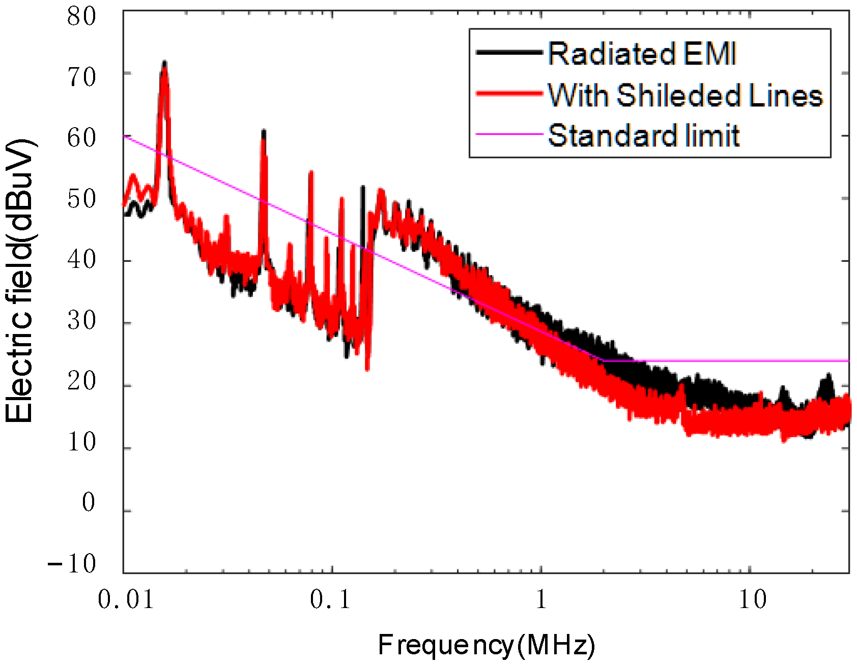
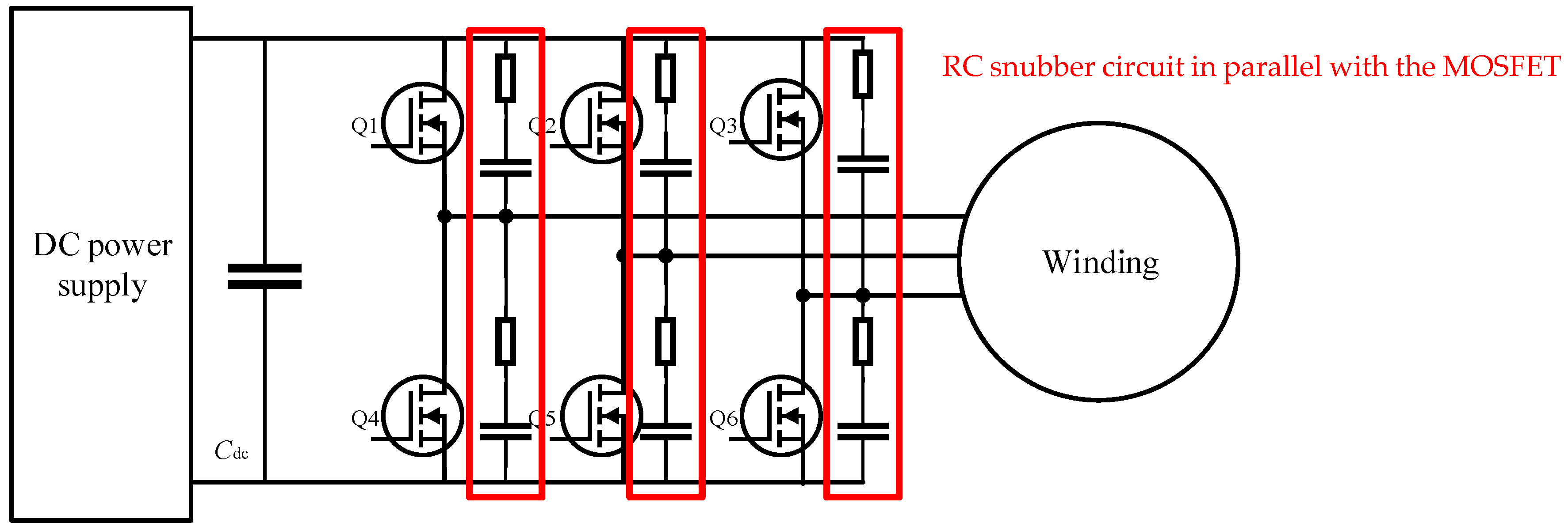
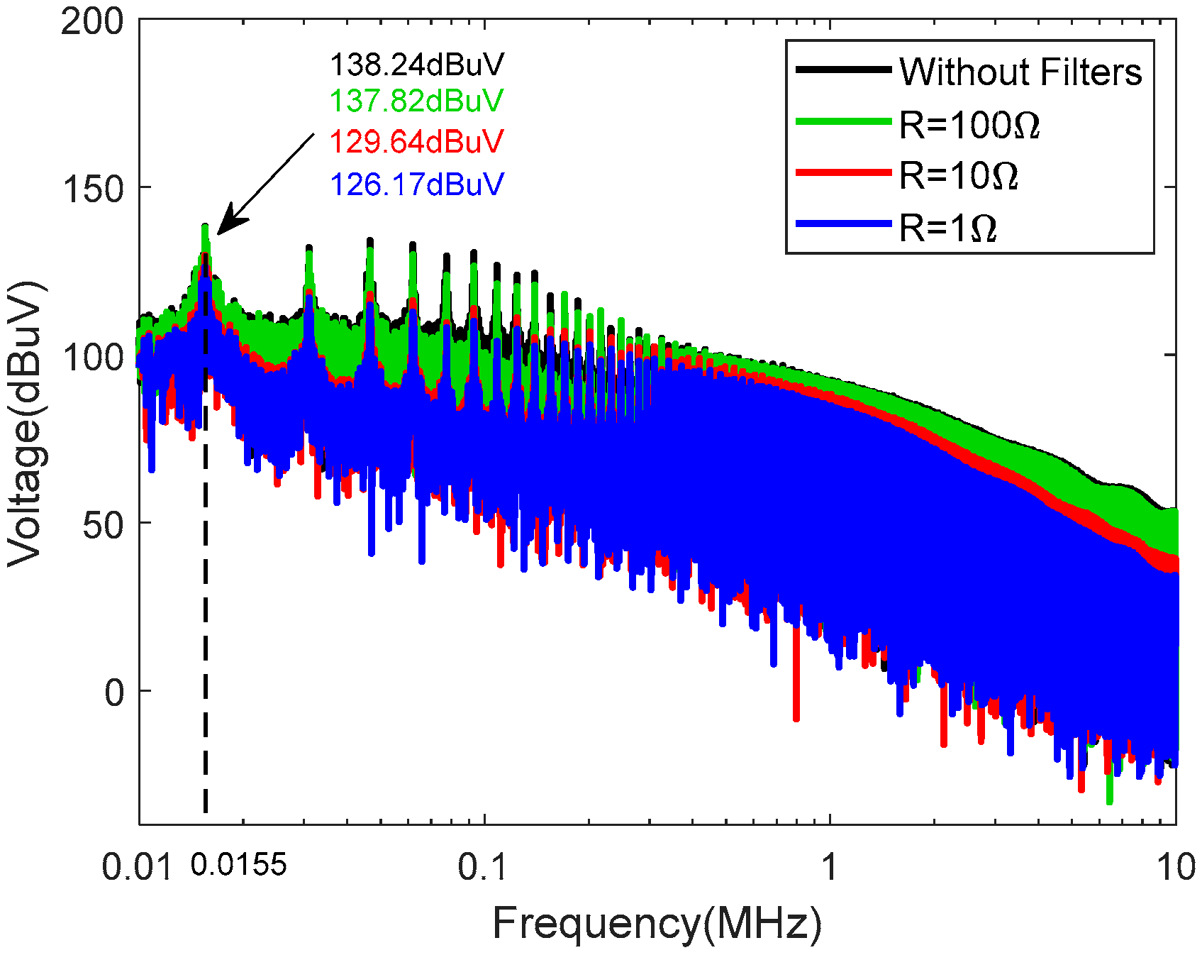
4. Filter Suppression of Radiated Interference

According to the analysis of the interference path and the main source of radiation, the interference voltage was generated by the switching device in the inverter circuit, which entered the windings of the fan and caused radiated interference.
The voltage for the port of the windings was calculated via the field-circuit simulation model shown in Figure 13. Taking the U phase as an example, the simulation results are presented in Figure 19, compared with the spectrum of the voltage at the winding port obtained by FFT. The calculation results demonstrate a consistency between the simulation and measurement. Therefore, the circuit simulation model can effectively guide the design of EMI filters.
For the filter circuit topology design, if the low-pass filter includes an inductive component, the inductance value of the selected device will be at the mH level due to the lowest frequency of the interference peak of 15.5 kHz, resulting in a large filter size. As a miniaturized motor, axial flow fans have limited internal space, which makes it challenging to accommodate larger-sized components. Hence, this paper proposes a non-inductive RC snubber circuit connected in parallel between the drain and source of each MOSFET, absorbing the voltage peaks due to high-frequency switching. The circuit topology is shown, and the RC snubber circuit in parallel with the MOSFET is marked in red in Figure 20.
The determination of RC parameters was achieved through circuit simulation. By adding parallel resistor and capacitor elements in the circuit simulation of Figure 13, the parameter combinations of resistors and capacitors in the filter were varied separately, and the absorption effect of the filter was measured by calculating the frequency-domain voltages of the winding. Using this simulation model, we calculated the winding voltage under two scenarios:
1. With a fixed capacitance of C = 10 μF, the resistance values were varied as R = 1 Ω, 10 Ω, and 100 Ω.
2. With a fixed resistance of R = 10 Ω, the capacitance values were varied as C = 1 μF, 10 μF, and 100 μF.
As depicted in Figure 21 and Figure 22, the comparison of peak voltages with the voltage without filter across the winding terminals revealed that a smaller resistor and a larger capacitor yielded a more effective suppression of peak voltages. Additionally, to preclude overcurrent in the circuit, the resistance should not be chosen to be excessively small. Furthermore, considering the spatial constraints of the PCB, the capacitor value should also not be excessively large. The parameters of the filter were determined as R = 10 Ω, C = 10 μF.
The device met the space size requirements of the fan and can be integrated into the PCB as shown in Figure 23. The red squares mark where the RC devices were installed, in parallel with each MOSFET. The control PCB was designed and directly processed by the authors for the integration of the complete fan, which is a four-layer board including key components such as MCUs, inverter circuits, and RC filter circuits.
The comparative results before and after filtering for the fan radiated interference measurement are shown in Figure 24. The measurement results show that the designed RC filter had a significant absorption effect on the radiated interference in the frequency band. Radiated interference attenuation reached a maximum of 41.9 dB. Peak radiated interference in the frequency band was reduced below the standard limits. Meanwhile, during the experimental measurements, the speed of the fan was not affected by the access to the filter, which indicates that the designed filter can suppress radiated interference without affecting the effective signal insertion loss.

5. Conclusions

EMC standards require stricter radiated emission limits for a PWM axial fan and its drive system. Meanwhile, due to the limited internal space of the small fan, there are also certain size requirements for the interference suppression measures. Therefore, this paper aimed to identify the main sources of radiated interference in PWM-regulated fans through measurements and simulations of radiated emissions. Additionally, a radiated interference suppression method that can be integrated into a PCB was proposed.
The propagation paths of the interference were determined through the study of the fan speed control mechanism. By modeling the radiated interference of individual components in the fan, the primary sources of radiated interference were identified. Subsequently, a small-sized peak-absorbing circuit was designed to address the issue. Experimental verification was conducted to assess the effectiveness of the radiated interference suppression measures. The experimental results demonstrate that the integrated non-inductive RC filter effectively suppressed peak radiated interference from the fan without impacting the fan’s speed. The insertion loss achieved by the designed filter for radiated interference reached 41.9 dB.

Author Contributions

Conceptualization, J.Y., Formal analysis, Y.W.; Investigation, C.W.; Methodology, J.Y. and X.Z.; Resources, X.Z.; Supervision, P.D., Validation, J.Y. and Y.W., Writing—original draft, J.Y., Writing—review & editing, P.D. All authors have read and agreed to the published version of the manuscript.

Funding

This work was supported by the National Natural Science Foundation of China under Grant 52175218.

Institutional Review Board Statement

Not applicable.

Informed Consent Statement

Not applicable.

Data Availability Statement

The data supporting the findings of this study are available from the corresponding author upon reasonable request.

Conflicts of Interest

The authors declare no conflict of interest.

References

  1. Zhai, L.; Hu, G.; Song, C.; Lv, M.; Zhang, X. Comparison of Two Filter Design Methods for Conducted EMI Suppression of PMSM Drive System for Electric Vehicle. IEEE Trans. Veh. Technol. 2021, 70, 6472–6484. [Google Scholar] [CrossRef]
  2. Nan, C.; Ayyanar, R.; Xi, Y. A 2.2-MHz Active-Clamp Buck Converter for Automotive Applications. IEEE Trans. Power Electron. 2018, 33, 460–472. [Google Scholar] [CrossRef]
  3. Carobbi, C.F.M.; Izzo, D. Evaluation and Improvement of the Reproducibility of CISPR 25 ALSE Test Method. IEEE Trans. Electromagn. Compat. 2018, 60, 1069–1077. [Google Scholar] [CrossRef]
  4. Zhang, B.; Wang, S. A Survey of EMI Research in Power Electronics Systems With Wide-Bandgap Semiconductor Devices. IEEE J. Emerg. Sel. Top. Power Electron. 2020, 8, 626–643. [Google Scholar] [CrossRef]
  5. Leuchter, J.; Stekly, V.; Blasch, E. Investigation of avionics power switch loading versus aircraft electromagnetic compatibility. IEEE Aerosp. Electron. Syst. Mag. 2015, 30, 24–34. [Google Scholar] [CrossRef]
  6. Touré, B.; Schanen, J.L.; Gerbaud, L.; Meynard, T.; Roudet, J.; Ruelland, R. EMC Modeling of Drives for Aircraft Applications: Modeling Process, EMI Filter Optimization, and Technological Choice. IEEE Trans. Power Electron. 2013, 28, 1145–1156. [Google Scholar] [CrossRef]
  7. Jing, L.; Du, M.; Wei, K.; Hurley, W.G. An Improved Behavior Model for IGBT Modules Driven by Datasheet and Measurement. IEEE Trans. Electron Devices 2020, 67, 230–236. [Google Scholar] [CrossRef]
  8. Hikage, T.; Yamagishi, M.; Shindo, K.; Nojima, T. Active implantable medical device EMI estimation for EV-charging WPT system based on 3D full-wave analysis. In Proceedings of the 2017 Asia-Pacific International Symposium on Electromagnetic Compatibility (APEMC), Seoul, Republic of Korea, 20–23 June 2017; pp. 87–89. [Google Scholar]
  9. Bellan, D. Circuit models for EMC analysis of CM current in three-phase motor drive systems. In Proceedings of the 2014 6th IEEE Power India International Conference (PIICON), Delhi, India, 5–7 December 2014; pp. 1–5. [Google Scholar]
  10. Zhai, L.; Song, C. Conducted EMI from motor drive system of electric vehicle under load operation. In Proceedings of the 2017 Asia-Pacific International Symposium on Electromagnetic Compatibility (APEMC), Seoul, Republic of Korea, 20–23 June 2017; pp. 181–183. [Google Scholar]
  11. Moreau, M.; Idir, N.; Moigne, P.L. Modeling of Conducted EMI in Adjustable Speed Drives. IEEE Trans. Electromagn. Compat. 2009, 51, 665–672. [Google Scholar] [CrossRef]
  12. Ji, J.; Wu, W.; He, Y.; Lin, Z.; Blaabjerg, F.; Chung, H.S.H. A Simple Differential Mode EMI Suppressor for the LLCL-Filter-Based Single-Phase Grid-Tied Transformerless Inverter. IEEE Trans. Ind. Electron. 2015, 62, 4141–4147. [Google Scholar] [CrossRef]
  13. Kumar, M.; Jayaraman, K. Design of a Modified Single-Stage and Multistage EMI Filter to Attenuate Common-Mode and Differential-Mode Noises in SiC Inverter. IEEE J. Emerg. Sel. Top. Power Electron. 2022, 10, 4290–4302. [Google Scholar] [CrossRef]
  14. Costa, F.; Gautier, C.; Revol, B.; Genoulaz, J.; Démoulin, B. Modeling of the near-field electromagnetic radiation of power cables in automotives or aeronautics. IEEE Trans. Power Electron. 2013, 28, 4580–4593. [Google Scholar] [CrossRef]
  15. Wei, S.; Pan, Z.; Yang, J.; Du, P. A Fast Prediction Approach of Radiated Emissions From Closely-Spaced Bent Cables in Motor Driving System. IEEE Trans. Veh. Technol. 2022, 71, 6100–6109. [Google Scholar] [CrossRef]
  16. Yang, J.; Zhao, X.; Xia, J.; Zhang, W.; Du, P.; Nie, B. An Equivalent Modeling Method for Electromagnetic Radiation of PWM Fans with Multiple Radiation Sources. Appl. Sci. 2025, 15, 2887. [Google Scholar] [CrossRef]
  17. Huibin, Z.; Jih-Sheng, L.; Hefner, A.R.; Yuqing, T.; Chingchi, C. Modeling-based examination of conducted EMI emissions from hard- and soft-switching PWM inverters. IEEE Trans. Ind. Appl. 2001, 37, 1383–1393. [Google Scholar] [CrossRef]
  18. Chang, C.-H.; Cheng, H.-L.; Chang, E.-C. Using the buck-interleaved buck–boost converter to implement a step-up/down inverter. Eng. Comput. 2017, 34, 272–284. [Google Scholar] [CrossRef]
  19. Guo, X.; Yang, Y.; Zhu, T. ESI: A Novel Three-Phase Inverter With Leakage Current Attenuation for Transformerless PV Systems. IEEE Trans. Ind. Electron. 2018, 65, 2967–2974. [Google Scholar] [CrossRef]
  20. Huang, J.; Shi, H. Reducing the Common-Mode Voltage through Carrier Peak Position Modulation in an SPWM Three-Phase Inverter. IEEE Trans. Power Electron. 2014, 29, 4490–4495. [Google Scholar] [CrossRef]
  21. Ramaiah, V.J.; Keerthipati, S. Hybrid PWM Scheme for Pole-Phase Modulation Induction Motor Drive Using Carrier-Based Hexagonal and Octadecagonal SVPWM. IEEE Trans. Ind. Electron. 2020, 67, 7312–7320. [Google Scholar] [CrossRef]
  22. Jiang, Y.; Wu, W.; He, Y.; Chung, H.S.H.; Blaabjerg, F. New Passive Filter Design Method for Overvoltage Suppression and Bearing Currents Mitigation in a Long Cable Based PWM Inverter-Fed Motor Drive System. IEEE Trans. Power Electron. 2017, 32, 7882–7893. [Google Scholar] [CrossRef]
  23. Han, D.; Morris, C.T.; Sarlioglu, B. Common-Mode Voltage Cancellation in PWM Motor Drives with Balanced Inverter Topology. IEEE Trans. Ind. Electron. 2017, 64, 2683–2688. [Google Scholar] [CrossRef]
  24. Chuang, C.-C.; Hua, C.-C.; Hung, C.-W.; Yao, C.-J. Study on Evaluating the EMI Filter for Electronic Communication Fans. J. Robot. Netw. Artif. Life 2022, 8, 269–272. [Google Scholar] [CrossRef]
  25. Qiu, H.; Wang, S.; Sun, F.; Wang, Z.; Zhang, N. Transient Electromagnetic Field Analysis for the Single-Stage Fast Linear Transformer Driver with Two Different Configurations Using the Finite-Element Method and Finite Integration Technique. IEEE Trans. Magn. 2020, 56, 7515805. [Google Scholar] [CrossRef]
Figure 1. Structure of the axis flow fan.
Applsci 15 04568 g001
Figure 2. Radiated interference generated in the axial flow fan.
Applsci 15 04568 g002
Figure 3. Schematic diagram of the fan drive system.
Applsci 15 04568 g003
Figure 4. Driving signal of each bridge arm.
Applsci 15 04568 g004
Figure 5. Radiation emission measurement configuration.
Applsci 15 04568 g005
Figure 6. Radiation emission measurement site.
Applsci 15 04568 g006
Figure 7. Measurement results of radiated interference.
Applsci 15 04568 g007
Figure 8. Paths of CM interference.
Applsci 15 04568 g008
Figure 9. Paths of DM interference.
Applsci 15 04568 g009
Figure 10. Schematic diagram of radiated emissions from a fan.
Applsci 15 04568 g010
Figure 11. Comparison of radiated interference before and after the use of shielded lines.
Applsci 15 04568 g011
Figure 12. Hybrid modeling approach for windings.
Applsci 15 04568 g012
Figure 13. Field-circuit radiation simulation model for winding-inverter circuits.
Applsci 15 04568 g013
Figure 14. Field-circuit radiation simulation model for control PCB-inverter circuits.
Applsci 15 04568 g014
Figure 15. Full-wave simulation models of the winding and the control PCB with the impeller and the fan frame.
Applsci 15 04568 g015
Figure 16. Comparison of the simulation results of the winding-radiated EMI and the PCB-radiated EMI with the measurement results.
Applsci 15 04568 g016
Figure 17. Simulation results of PCB surface current.
Applsci 15 04568 g017
Figure 18. Voltage at three-phase winding ports in the time-domain.
Applsci 15 04568 g018
Figure 19. Comparison of the simulation results of the winding voltages with the measurement results. (a) Measurement results; (b) simulation results.
Applsci 15 04568 g019
Figure 20. RC filter circuit topology.
Applsci 15 04568 g020
Figure 21. Simulation results of winding voltages with different R when C = 10 μF.
Applsci 15 04568 g021
Figure 22. Simulation results of winding voltages with different C when R = 10 Ω.
Applsci 15 04568 g022
Figure 23. Control PCB with integrated RC filter.
Applsci 15 04568 g023
Figure 24. Comparison results of radiated interference before and after filtering.
Applsci 15 04568 g024
Disclaimer/Publisher’s Note: The statements, opinions and data contained in all publications are solely those of the individual author(s) and contributor(s) and not of MDPI and/or the editor(s). MDPI and/or the editor(s) disclaim responsibility for any injury to people or property resulting from any ideas, methods, instructions or products referred to in the content.

