Article

Analysis of the Dynamic Wheel Loads in Railway Transition Zones Considering the Moisture Condition of the Ballast and Subballast

1
Railway section, Delft University of Technology, 2628CN Delft, The Netherlands
2
Roadscanners Oy, 33100 Tampere, Finland
*
Author to whom correspondence should be addressed.
Appl. Sci. 2017, 7(12), 1208; https://doi.org/10.3390/app7121208
Submission received: 28 October 2017 / Revised: 20 November 2017 / Accepted: 21 November 2017 / Published: 23 November 2017
(This article belongs to the Section Mechanical Engineering)

Abstract

:
Transition zones in railway tracks are the locations with considerable changes in vertical support structures, e.g., near bridges. Due to possible water flow constrictions in transition zone structures, there is frequently an increased moisture level in the ballast/subballast layers, which is a potential source of track degradation. This paper presents results of the moisture condition measured in three transition zones using ground penetrating radar, where the ballast/subballast are analyzed. The relationship between the moisture condition and track degradation in the transition zones is studied by comparing it to the longitudinal track level that is measured by the track inspection coaches. A strong connection is found between the high moisture condition and track degradation in the transition zones. The dynamic behavior of the transition zones with high moisture condition is analyzed using the Finite Element method. Differential stiffness and settlement are taken into consideration in the transition zone model, which is also coupled with a vehicle. The ballast/subballast layers are modelled as solid elements. Increased moisture conditions are considered as a reduction of elastic modulus, according to laboratory findings. Results show that high moisture leads to an increase of dynamic wheel loads in the transition zone, which explains the connection and confirms that the high moisture condition is a source of transition zone problems.

Graphical Abstract

1. Introduction of Transition Zones

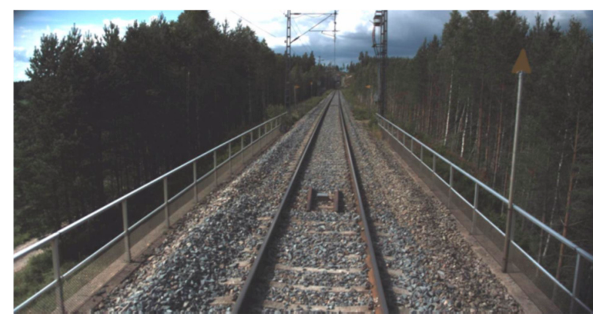
Transition zones in railway track network are locations with considerable changes in track support structures. Typically, they are located near concrete structures, such as bridges, culverts, and tunnels. An example of a bridge transition zone is shown in Figure 1.
The track geometry in transition zones degrades at a much faster rate than that of open tracks [1,2,3,4], which results in the appearance of a “dip” [5]. This phenomenon has been confirmed by a survey of the performance of track transition zones, which revealed that 51% of the track transition zones had experienced such a settlement [6]. In the field measurement of a bridge transition zone [4], the rail displacements on multiple locations were measured during train passages. Results showed a 5.1 mm deep dip in the ballast track. A dip was also found in the transition zone of level crossing in [7], which was 5.3 mm in depth.
Such large geometry irregularity leads to an increase of dynamic wheel loads [8] and the redistribution of dynamic wheel loads [3]. The increased dynamic wheel loads may damage track components, for example [1,2,3,6,9,10,11,12,13,14,15,16,17]:
  • rail surface defects and cracks in the rail foot;
  • broken fasteners;
  • cracks in concrete sleepers;
  • breakage of ballast particles and voids between sleepers and ballast, also known as hanging sleepers.
It also initiates the further deterioration of track geometry, causing a self-perpetuating system [15,17,18,19,20,21]. Increased dynamic wheel loads can result in worsening of the passenger’s comfort [18], and can even create a potential for train derailment.
As a result, transition zones require more maintenance, like tamping and adding ballast, as compared to open tracks [11,22]. For instance, in the Netherlands, maintenance activities on the track in transition zones are performed up to 4–8 times more often than on open tracks [14,23]. In the United States (US), $200 million is spent annually on maintenance of the track in transition zones, while in Europe, about €97 million is spent on similar maintenance activities [24,25].
The major factors causing transition zone problems can be divided into three categories [1,6,22]:
  • Significant abrupt changes in the vertical stiffness of the track;
  • Differential settlement or uneven profile of the ballast track, which inherently settles more than a concrete structure;
  • Geotechnical issues, such as poor drainage conditions and poor quality of materials.
Many studies have been conducted to analyse the former two factors in transition zones, such as in [6,8,11,17]. A thorough review can be found in [26]. The geotechnical factor has been studied less, which is mainly due to the limitations of measurement methods. For instance, the inspection of the ballast quality was typically conducted by excavating samples from ballast layers, which is costly, destructive, and needs track possession time.
The moisture condition of the ballast may play an important role in the rapid degradation of tracks and consequently geometry irregularities. Excess water in substructures significantly reduces (around 50%) the resilience of tracks [27,28] and increases (around 40%) track settlement [29,30,31]. The loss in resilient modulus and the increase of settlement have significant implications for transient vertical displacements and track performance.
This paper presents an experimental analysis of the moisture condition to explore the relationship between moisture and track condition in transition zones. In total, three transition zones of various conditions are analysed. The moisture condition in the transition zones is measured by the use of ground penetrating radar (GPR) [32,33], which is compared to the track geometry that is measured by inspection coaches. The relationship between moisture condition and geometry irregularity is analysed.
Transition zones in high moisture condition are numerically studied using the Finite Element (FE) method. The transition zone model accounts for differential stiffness and settlement at the same time, which is developed in [8,34], and validated in [35]. Ballast and subballast layers are modelled as solid elements and high moisture conditions are considered as a reduction of elastic modulus. The wheel loads of the transition zone in the high moisture case are compared with a reference case to analyse the effect of moisture conditions.
The paper is organised as follows. Research for the moisture condition in ballast is reviewed in Section 2. The experimental study of the moisture condition in transition zones is presented in Section 3. In Section 4, the transition zone in high moisture condition is analysed using the FE method. Finally, conclusions are given in Section 5.

2. Review of the Mechanism of Saturated Ballast

Drainage, as one of the most important functions of track structure, can intercept subsurface water entering the area of the track substructure, intercept surface water approaching the track structure from sides, and remove water draining out of the ballast and subballast [36].
There are three sources of water entering the track substructure: precipitation falling onto the tracks, water flowing down along adjacent slopes, and water seeping upward from the subgrade [36]. The track structure is designed to provide an adequate drainage function. However, due to the special structure in transition zones, e.g., abutment, the water may not be drained efficiently. The excess water in the substructure significantly reduces the resilience [27,28] and increases the settlement [29,30,31,36] of tracks. The problem becomes particularly severe when the substructure reaches a saturated state, leading to considerable increases in track maintenance costs [27,36].
The resilient modulus of most of the untreated granular materials has a notable dependence on moisture content, where the modulus decreases with the growth of saturation level [27]. For instance, in [37], a 50% decrease in resilient modulus in the gravel was observed as the degree of saturation increased from 70% to 97%. A field measurement using seismic surface waves in [28] found a 50% decrease of (fouled) ballast modulus when the ballast is saturated. The reason is due to the excess pore-water pressure that is developed by the saturated granular materials under repeated loading. As the pore-water pressure develops, the effective stress in ballast decreases with a subsequent reduction in both strength and stiffness of ballast bed [27].

3. Experiment Analysis of Transition Zones

Although a poor drainage condition is considered as one reason for the track degradation in transition zones, it has not been experimentally analysed in detail in the field. This section presents the measurement of moisture condition in transition zones using GPR. The relationship between moisture condition and track geometry is also studied.

3.1. Introduction of GPR

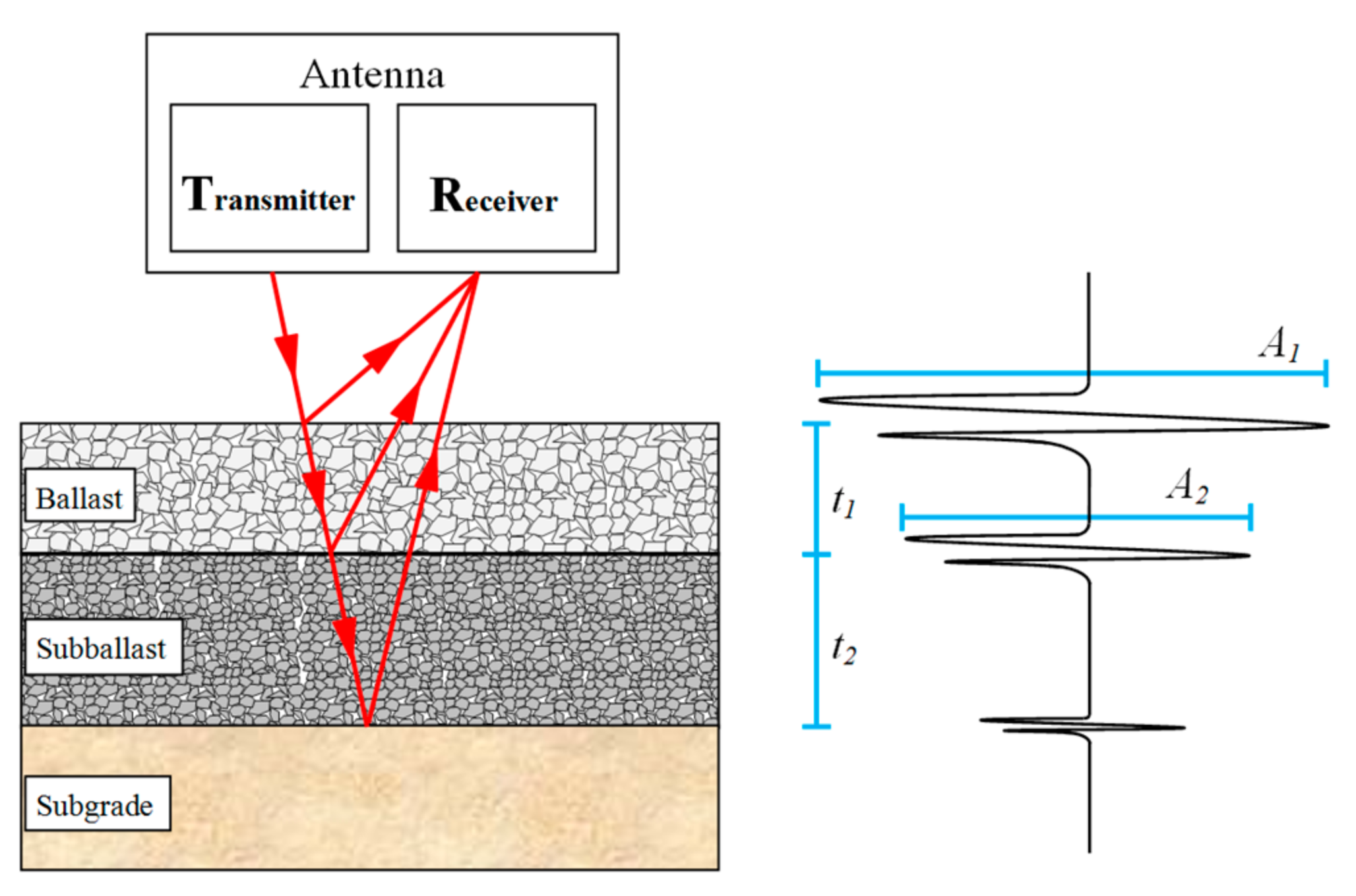
GPR uses a radio wave source to transmit a pulse of electromagnetic energy into the inspected medium [33]. Its principle in railway measurements is shown in Figure 2. GPR is an effective and non-invasive tool for mapping railway structures and analysing subsurface conditions. The reflected energy, originating from the interfaces between materials of different dielectric properties, is received and recorded for analysis. GPR data consists of changes in reflection amplitude, changes in the arrival time of specific reflections, and signal attenuation [32,38]. The method provides a continuous profile of the thickness and properties of railway structures, which can be used to analyse the quality of track substructures, such as the moisture susceptibility of ballast and subballast, fouling of ballast, layer deformation, and mud pumping [39,40,41].
GPR measurements for this case study were performed using a GSSI SIR-30 GPR system, manufactured by Geophysical Survey Systems Inc., Nashua, NH, USA, including a 400 MHz antenna attached to a VR-Track Ltd Tka-8 maintenance engine, as illustrated in Figure 3.
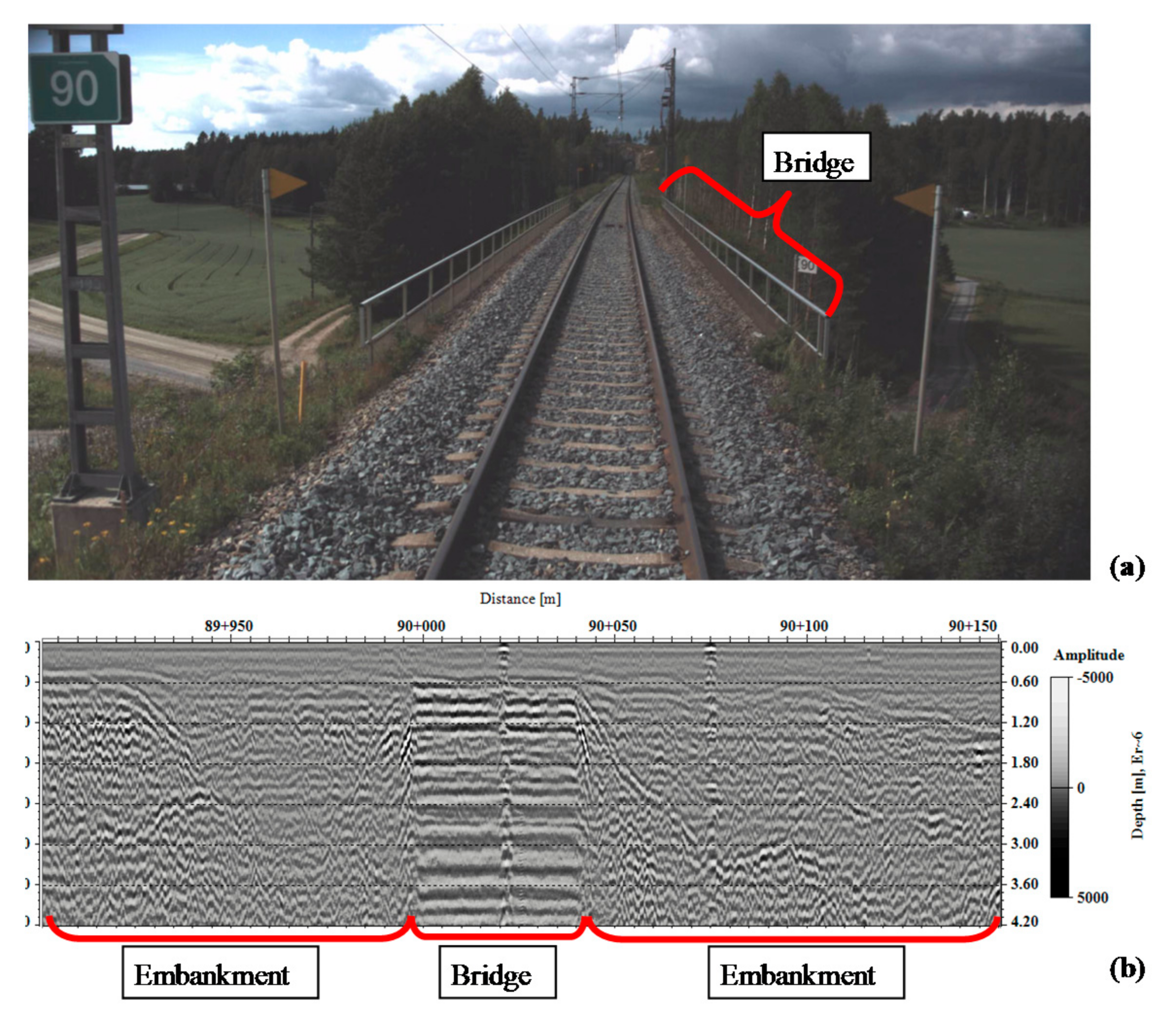
The GPR antenna can be lifted to 0.3 m above the sleeper level and the maximum survey speed is up to 160 km/h, depending on data collection settings. The data collection rate was controlled by a distance measurement instrument. During the survey, GPS coordinates and digital video were recorded using Rail Doctor™ Camlink software, developed by Roadscanners Oy, Rovaniemi, Finland. The processing, visualization, interpretation, and analysis of the GPR data are performed using the Rail Doctor software (version 3.2), developed by Roadscanners Oy, Rovaniemi, Finland, 2017. The measurement system has been calibrated against sample analysis [38] and pit tests [39]. A screenshot from the recorded video is shown in Figure 4a, wherein a transition zone consisting of embankment and a bridge can be found. A measurement result from GPR at the corresponding location is shown in Figure 4b. The right axis of Figure 4b indicates the depth, in meters, beneath the top of sleepers (or below rails). The ballast layer is located from 0 m to 0.6 m below rails, where the ballast at 0–0.25 m is between sleepers and 0.25–0.6 m is below sleepers. The subballast is located from 0.6 m to 1.2 m, and below 1.2 m is embankment and subgrade. It should be noted that sleepers are filtered during the data processing to obtain a better visualization of the data. The lateral axis of Figure 4b is the distance or location, which is in the form of “km + m”. The two sides of the bridge in a transition zone are named as the embankment-bridge side and the bridge-embankment side in the paper depending on the train moving direction. The moving directions of the results presented in this paper are all from left to right. Therefore, the embankment-bridge side is always on the left side of bridges (before the bridges) and the bridge-embankment side on the right side (after the bridges).
Dielectric properties decide the amplitude, arrival time, and signal attenuation of reflections, and they are different with a higher content of fines and water [42]. The dielectric constant and the velocity of the signal in various materials are shown in Table 1 [43]. This difference can be detected by analysing the GPR signal [38,43,44]. As a result, the distribution of the relative moisture susceptibility in ballast and subballast can be obtained.
In the post-process stage, measurement results are transformed into frequency-domain data and are parameterized by means of a sliding calculation window in depth and longitudinal directions using the windowed Fourier transform (WFT) [39]. Results are then visualised as a colour-coded image, wherein the strong reflections (blue) indicate high moisture susceptibility and weak reflections (red) low. This method has been calibrated and utilized in [39,45,46]. A comparison of two moisture profiles is shown in Figure 5.

3.2. Measurement Results

The moisture condition of three bridge transition zones on a Finnish railway line was measured using GPR. To study the effect of the moisture condition, the longitudinal level (rail height) measured by track inspection coaches in a similar time period using a 5 m-chord method was also collected.
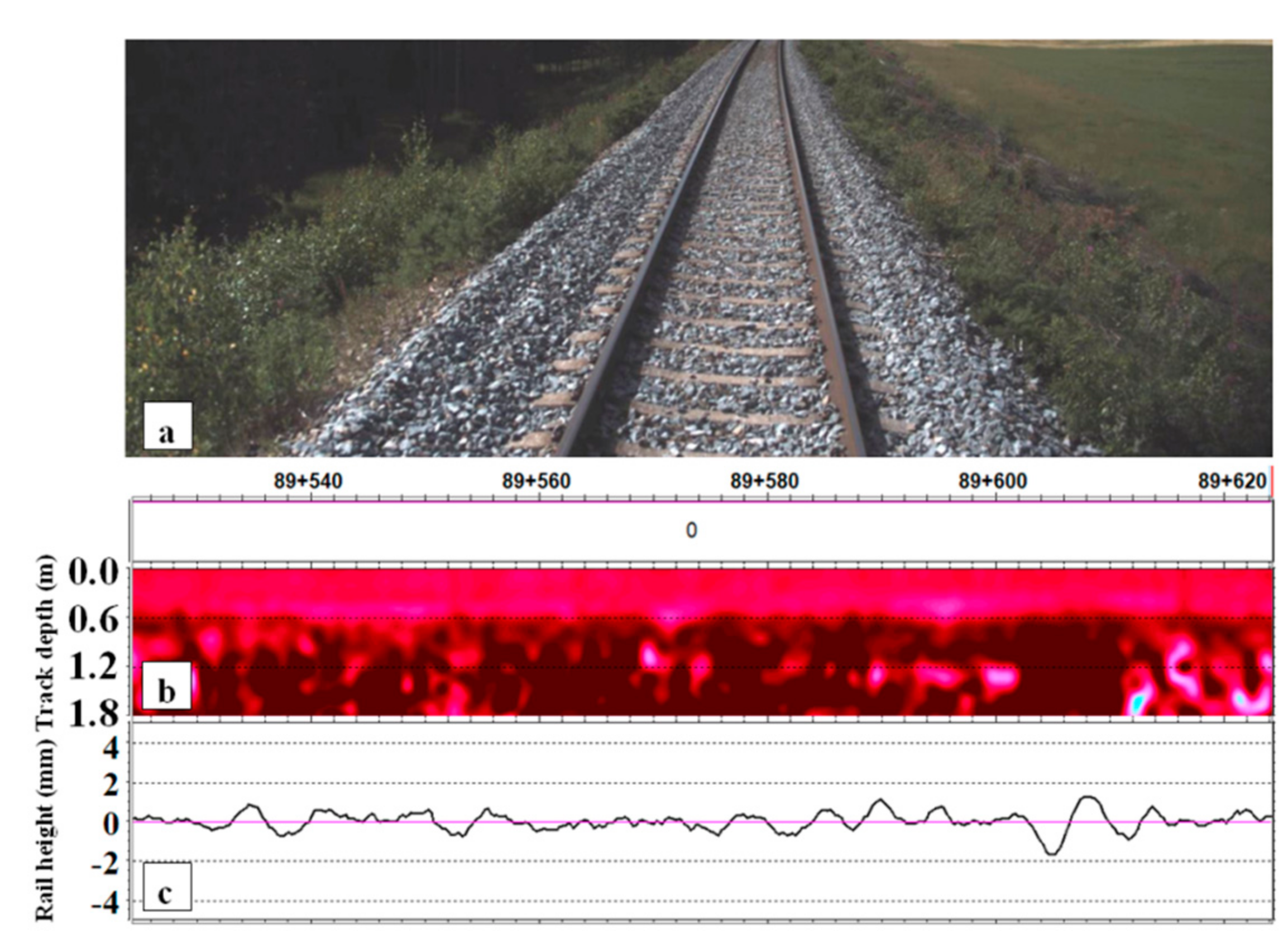
Measurement results of an open track section are shown in Figure 6 as a reference case. A photo of the track is shown in Figure 6a, the moisture profile in Figure 6b and longitudinal level (rail height) in Figure 6c. The vertical axis of the moisture profile (Figure 6b) indicates the depth under rails in meters. Although the subballast layer ideally ends 1.2 m, it often settles deeper, especially in transition zones. As a result, the measurement results are collected down to 1.8 m. The ballast, subballast, and subgrade are dry, as indicated by the red colour of the moisture profile. The irregularity of the longitudinal track level is less than 2 mm, which is relatively small.
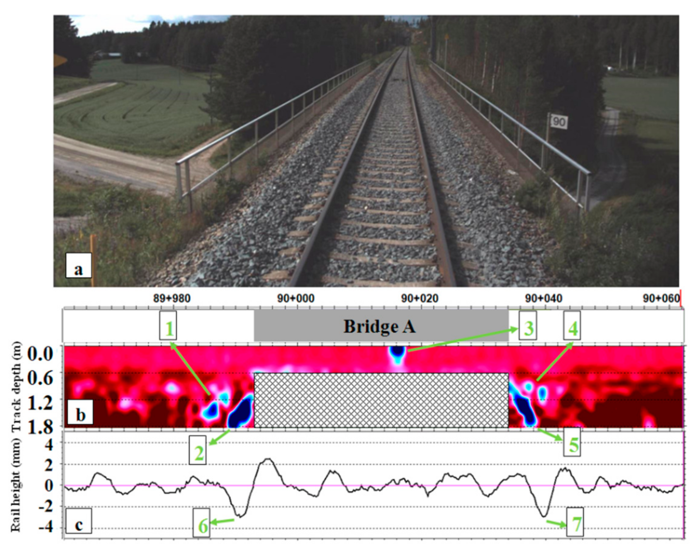
Measurement results from Transition Zone A are shown in Figure 7. This transition zone is composed of embankment and a 41 m long concrete bridge. The photo of the bridge taken by the on-board video camera (Figure 3) during the GPR measurements is shown in Figure 7a. The ballast is laid on the bridge, the depth of which is around 0.6 m beneath rails. GPR data from the concrete bridge is out of the focus of this study and it therefore blocked out. Approach slabs are employed at both ends of the bridge. The slabs are made of concrete and laid diagonally from the ballast layer to the subballast layer.
Moisture susceptibility increases before and after the bridge, as can be seen from Figure 7 (see the blue zones indicated by No. 1 and No. 4). The blue zones of No. 2 and No. 5 are caused by approach slabs, since the concrete has a similar expression as highly susceptible moisture areas after post-processing. Likewise, the blue zone from No. 3 is caused by a section of rail, as shown in Figure 8.
Figure 7c shows that the irregularity of the track increases significantly before and after the bridge (indicated by No. 6 and No. 7), which reached 3.0 mm and 2.9 mm, respectively. These two irregularities indicate the appearance of differential track settlement, which agrees with the dips found in other transition zones, such as in [4,6,7]. Transition Zone A has both increased moisture susceptibility and track irregularity based on the moisture profile and the longitudinal track level data on both ends of the bridge.
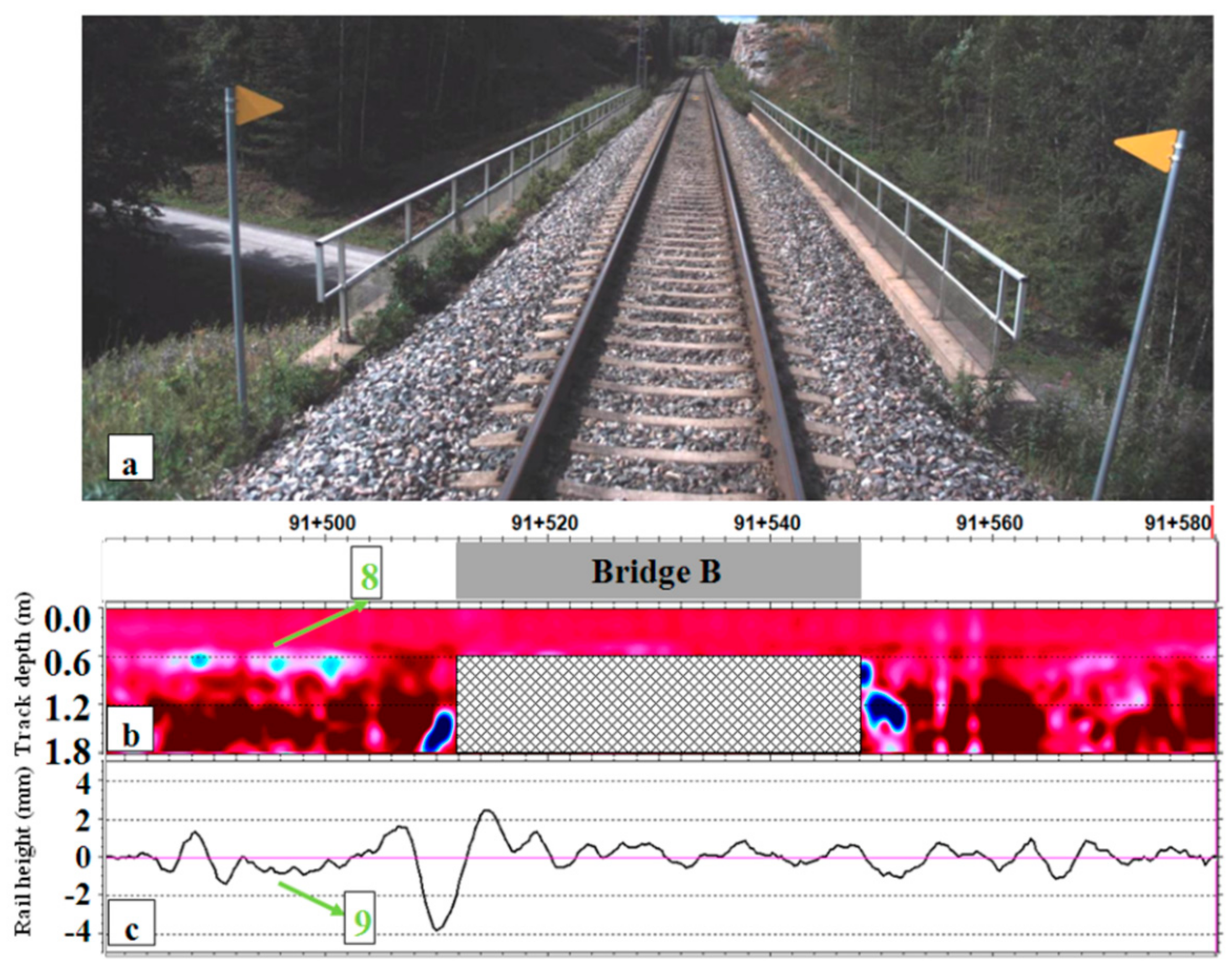
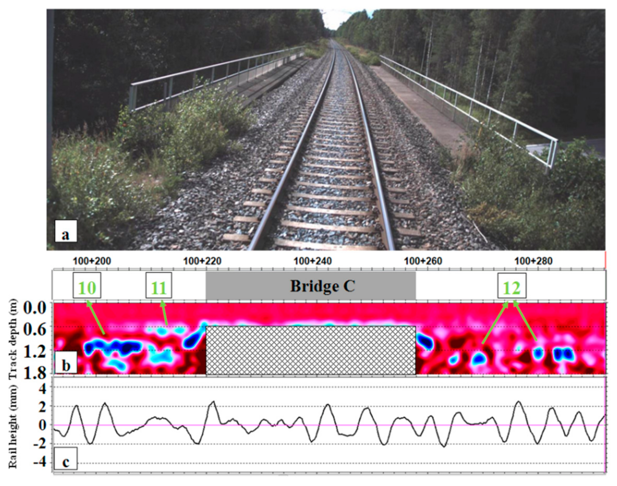
Measurement results of two more transition zones (named as Transition Zone B and Transition Zone C) are shown in Figure 9 and Figure 10. Their structures are similar to that of Transition Zone A.
Moisture susceptibility increases before the bridge in Transition Zone B. The blue area No. 8 (Figure 9) appears at the interface between the ballast layer and the subballast layer, which implies that the water is held at the bottom of the ballast and the drainage system is in poor condition. This is most likely one of the reasons for the track irregularity in the corresponding location (No. 9). However, no significant increase of the moisture can be found above the approaching slab, yet a large dip appears in the corresponding location. This irregularity could be caused by other reasons, such as a rail defect.
In the bridge-embankment side of Transition Zone B, the moisture in the ballast and the subballast layer is relatively low. As expected, the track geometry at the corresponding location is much smoother, as shown in Figure 9c.
Transition Zone C is in worse condition than Transition Zones A and B. The moisture susceptibility of the ballast and the subballast is significantly increased, both at the bottom of ballast (No. 11) and bottom of subballast (No. 10 and No. 12), as seen in Figure 10b. Severe track irregularity also appears through the entire transition zone, as shown in Figure 10c.
In summary, high moisture areas appear mostly before and after the bridges in all of the transition zones. They can be detected sometimes at the bottom of the ballast layer, bottom of subballast layer, and above the abutments. Track irregularities can also be found at corresponding locations, which implies a connection between high moisture condition and track degradation. When the moisture is high, the track irregularities are higher (see the embankment-bridge side of Transition Zone C, in Figure 10); when the moisture is low, the track irregularities are also low (see the bridge-embankment side of Transition Zone B, Figure 9).
Since the theoretical findings in Section 2 suggest that a high moisture in ballast leads to a reduction of stiffness, the high moisture in the structure can be considered as one of the sources for the extra degradation in transition zones. It should be noted that the high moisture is not the only source leading to the extra degradation, for instance, the large track irregularity above the approaching slab in the embankment-bridge side in Transition Zone B (Figure 9) is not caused by the moisture condition.

4. Finite Element Analysis of Transition Zones with High Moisture

Since a strong connection between the high moisture condition and track degradation is found from field measurement data, this section aspires to explain the connection using the FE method. The dynamic behaviour of transition zones with high moisture condition is analysed.

4.1. Introduction of the Finite Element Model

The FE model considering both the differential stiffness and settlement in transition zones is introduced in the section. The model that is used in this paper is based on the model proposed in [47] and further developed in [8,34]. The model consists of two ballast tracks and one track on the bridge in the middle, as shown in Figure 11. It is possible to analyse both the embankment-bridge and the bridge-embankment sides of the transition zone with a single calculation. In this model, the “bridge” is symbolical, which is simplified to reduce the calculation costs.
The length of ballast track is 48 m (one on each side) and the bridge is 24 m. Components of the ballast track are rails, fasteners, sleepers, ballast, and subgrade. The rails are modelled as beam elements with the cross-sectional and mass properties of UIC54 rails. Spring and damper elements between the rails and sleepers are used to model fasteners. The springs have bilinear properties in the vertical direction so that they have the stiffness of rail pads in compression, while the stiffness is much higher to simulate the clamping effect of fasteners in tension. Ballast, sleepers, and subgrade are modelled using fully integrated solid elements with elastic material properties. The ballast and subballast are considered as one layer, which is 0.9 m deep. There is no ballast between sleepers since its effect on settlement is negligible. It should be noted that the ballast, subballast and subgrade are simplified in the model. Despite the fact that the responses of unbound granular materials such as ballast, subballast, and subgrade can be more accurately modelled using nonlinear constitutive models, simplifications have to be adopted in the large-scale study (e.g., transition zones) to reduce the computational expense. Many studies (e.g., [10,48,49,50,51,52,53]) have proved that some behaviour of ballast and hanging sleepers can be modelled accurately using simplified methods (e.g., solid elements with elastic material properties). Following [10,48,49,50,51,52,53], the ballast and subgrade in this model are also modelled by solid elements with elastic material properties. The element length of 75 mm is used for the sleepers and the ballast (there are eight elements within one sleeper space). The thickness of the subgrade is 2 m.
The vehicle model is idealized as a multibody system consisting of one body, two bogies, and four wheelsets. The wheelsets are named Wheel 1 to 4 from the right to the left. Wheel 1 and 2 belong to the front bogie and the Wheel 3 and 4 belong to the rear bogie. Primary and secondary suspensions are modelled by spring-damper elements. The parameters are suggested by literature (vehicle parameters by [11,54,55], track parameter by [10,49,54,56]), and are then tuned according to field measurements [35]. The axle load of the vehicle is 19.0 t and velocity is 144 km/h. Material properties of the track components and vehicle used in the model are collected in Table 2.
The contact between wheels and rails is modelled using the linear Hertzian spring [56]. Silent boundaries are applied on both ends of the model in order to reduce the wave reflection effect. The nodes at the bottom of the subgrade and bridge are fixed.
The model considers differential settlement between the bridge and ballast track on both sides. After construction or tamping, ballast tracks will be compacted within a short period [36,57,58,59]. In this period, the large settlement appears in ballast tracks due to the volumetric compaction of particles. On the contrary, the tracks on bridges are barely settled, which generates a differential settlement in transition zones. It should be noted that the value of the differential settlement is important, but is difficult to measure precisely in reality. For instance, the void under sleepers measured in [11] had an error of 3 mm. The value of the differential settlement that is used in the paper is selected from the range of values that are frequently reported in field measurements of transition zones [14,23], which is 2–10 mm. A value of 4 mm is used, since it can represent the early period of a transition zone. Dynamic responses are expected to be larger for higher differential settlement values.
The nonlinear connection between sleepers and ballast is important for modelling of the ballast degradation mechanism [48,53]. In the case of hanging sleepers, the sleepers should generate a nonlinear interaction force to the ballast under compression and separable without loading [53]. Therefore, contact elements are applied between sleepers and ballast. According to the penalty algorithm that is employed in the contact elements, the search for penetrations between the bottom surface of sleepers and the top surface of ballast is made for every time step during the calculation. When penetration has been detected, a force that is proportional to the penetration depth is applied to resist and ultimately eliminate the penetration [60]. This method allows for simulating the impact on ballast, which is proportional to the downward acceleration of sleepers.
The simulation procedure consists of two phases. First, only the gravity forces are applied to the model. When the model reaches the equilibrium state, the velocity is applied to the vehicle, so that the vehicle moves from the left end to the right end of the transition zone passing the bridge. The mass-weighted nodal damping is applied globally to the nodes and the track’s random irregularity is not considered in this model. The model is solved using the commercial software LS-DYNA, version R8, developed by Livermore Software Technology Corporation, CA 94551, the US, 2015. The time-step is 1.3 × 10⁻⁵ s, and the calculation takes approximately 10 h using an 8-core (I7) workstation with High Parallel Computing (HPC).
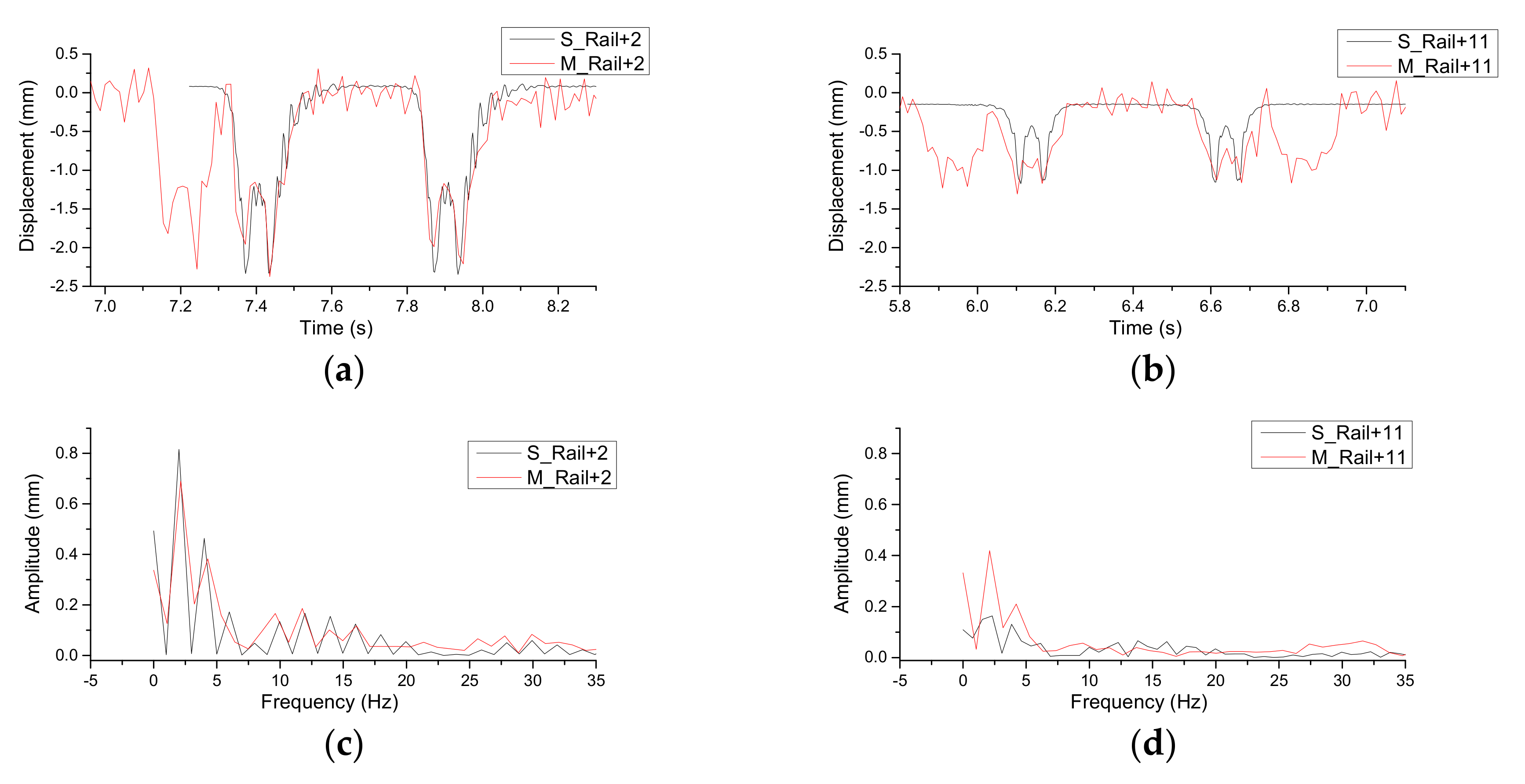
The model was validated against field measurements in [35]. The comparison between the simulated rail displacements and the calculated measurement displacements is shown in Figure 12. Rails from a close location (above the 2nd sleeper) and a far location (above the 11th sleeper), with respect to the bridge, are both compared. The measurement was performed using a Digital Image Correlation-device [4]. Results are filtered using a low-pass filter with cut-off frequency of 35 Hz. It should be noted that the model is tuned according to the measured transition zone. As it can be seen from Figure 12, the simulation results are in a good correlation with the measurement data both in the time and the frequency domains.

4.2. Simulation of the Transition Zone with High Moisture

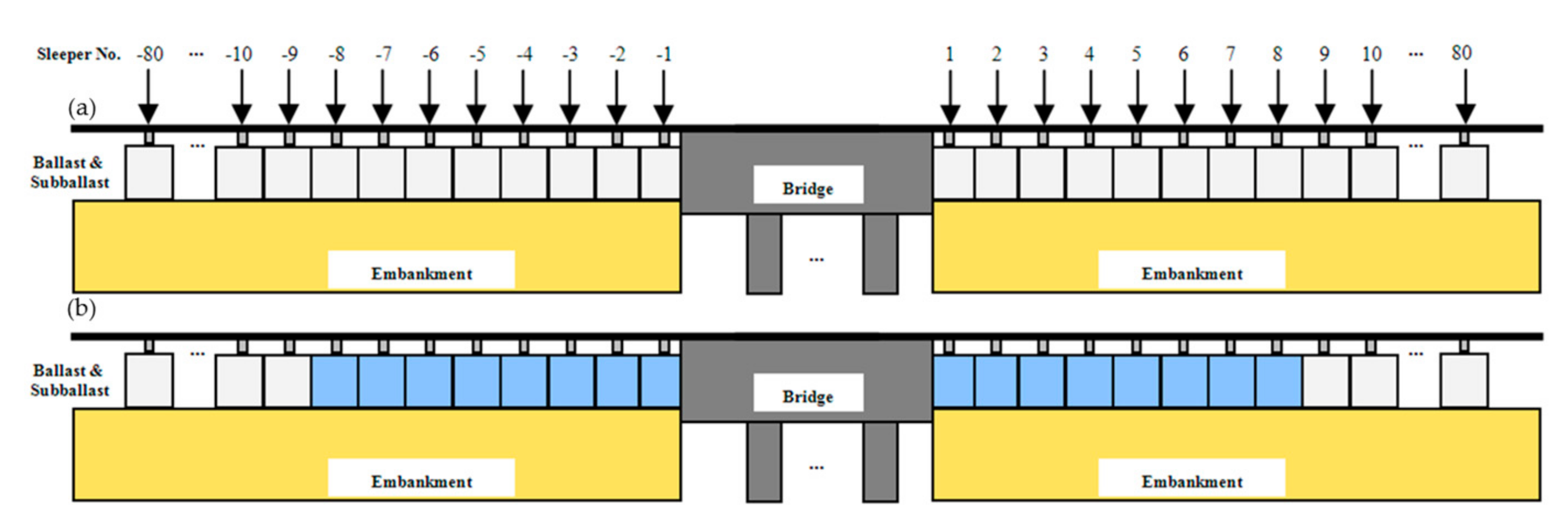
Ballast in transition zones often has poor drainage conditions [1,6,22]. High moisture in the ballast leads to an approximately 50% reduction in stiffness [27,28]. Therefore, the model considers ballast with high moisture in the transition zone by reducing stiffness by 50%. In this case, ballast areas in the transition zones assumed to be affected by high moisture (50% stiffness reduction) are within an 8-sleeper distance from the bridge and are shown with blue colour in Figure 13. The ballast stays unchanged in the reference case.

4.3. Results of the Finite Element Analysis

FE simulation results of the transition zones with and without high moisture are analysed in this section.
The dynamic wheel loads of Wheel 1 are shown in Figure 14. The horizontal axis represents the distance along the transition zone model, where the bridge is located between 48 m and 72 m. Dynamic wheel loads on the bridge are not analyzed here, and therefore their responses are covered by the shaded area. The dynamic wheel loads are zoomed before and after the bridge in Figure 14b,c, respectively.
As shown in Figure 14, the dynamic wheel load of Wheel 1 in the reference case is increased near the bridge, which is caused by the differential stiffness and settlement existing in the transition zone. This is one of the sources of degradation in transition zones. In addition, the dynamic wheel loads are different in the embankment-bridge and bridge-embankment sides. In the embankment-bridge side, the dynamic wheel loads are increased at a closer location to the bridge (at 47.4 m, 0.6 m from the bridge), while in the bridge-embankment side, the dynamic wheel loads are increased at a further location (at 73.2 m, 1.2 m from the bridge). This is caused by the different vehicle dynamics between the elevation and drop-off, which are theoretically studied in [17] and numerically studied in [8].
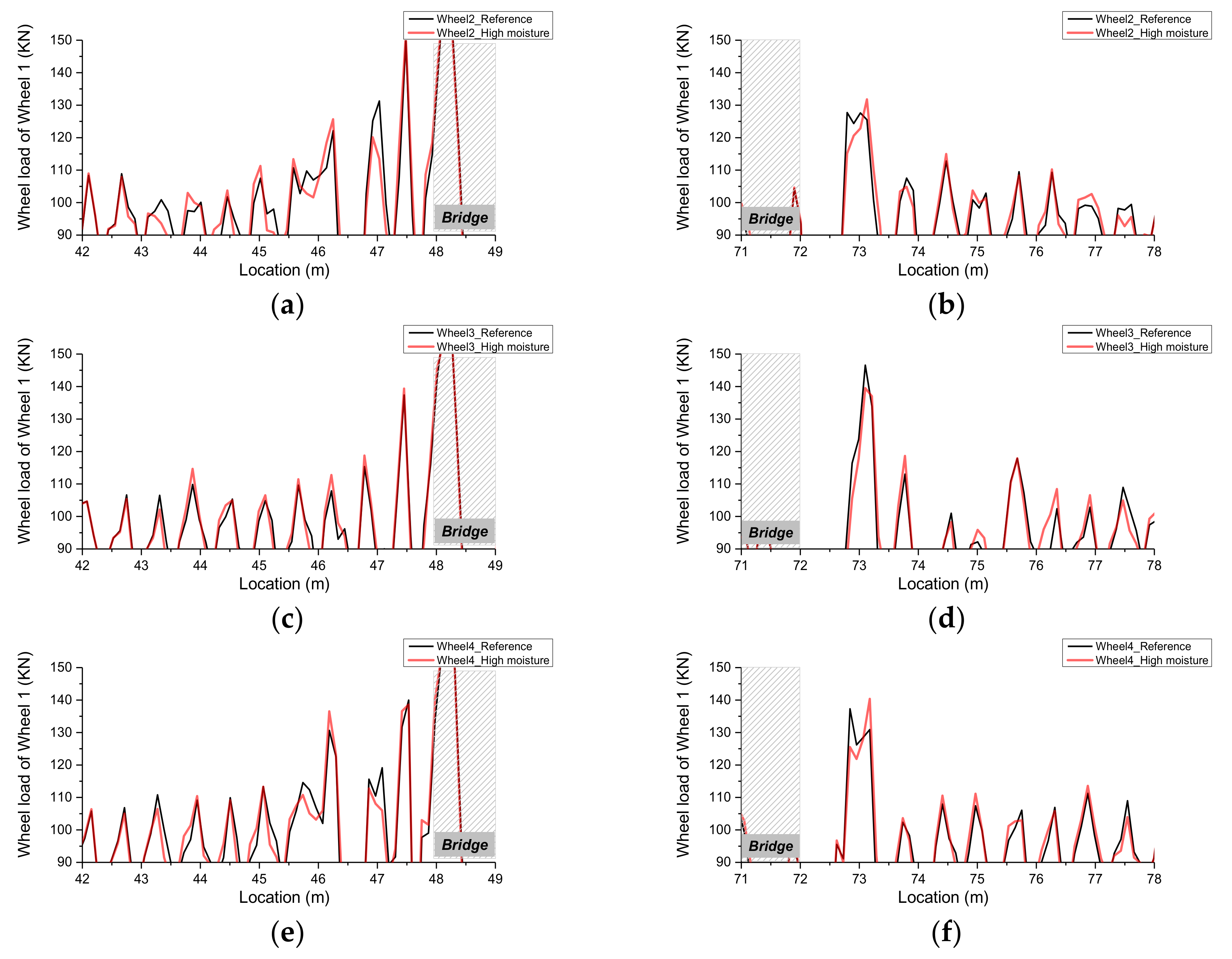
When comparing to the reference case, the dynamic wheel loads of Wheel 1 in the high moisture case are slightly increased at most of the locations before and after the bridge (43–48 m and 72–78 m), while they remain the same at further locations. This is reasonable since the stiffness of ballast is reduced only at these locations (8-sleeper distances, corresponding to 43.2–72 m and 72–76.8 m). Similarly, the slight increase is also found in the dynamic wheel loads of the other three wheels at most of the locations before and after the bridge, as shown in Figure 15. It should be noted that the dynamic wheel loads in the high moisture case are lower than that in the reference case at some individual peaks. This is caused by the dynamic vibration of the vehicle. To study the overall effect of high moisture, the statistics of increased percentage of the peaks close to the bridge (the closest seven peaks to the bridge on both sides, negative towards the bridge and positive away from the bridge, as indicated in Figure 14b,c) is performed, as shown in Table 3. The increase percentages of the dynamic wheel loads in the high moisture case with respect to those at the same location in the reference case are calculated.
As shown in Figure 15 and Table 3, the dynamic wheel loads of all the wheels in the high moisture case are increased, where average ranges are from 0.2% (Wheel 4) to 2.6% (Wheel 1). It should be noted that the negative values in Table 3 correspond to the peaks in Figure 14 and Figure 15 where the dynamic wheel loads in the high moisture case are lower than that in the reference case. The increase of the front wheels is higher than that of the rear wheels (Wheel 1 > Wheel 2, Wheel 3 > Wheel 4), and the increase of the front bogie is higher than that of the rear bogie (Wheel 1 > Wheel 3, Wheel 2 > Wheel 4). Because the higher dynamic wheel loads accelerate track degradation, the simulation results confirm that a high moisture condition is one of the sources of fast degradation that is often reported in transition zones. The increase of dynamic wheel loads also explains the irregularities in longitudinal track level, as shown in Section 3.
It should be noted that the vehicle used in the model is a passenger vehicle (19 t). In a real situation, freight trains with higher axle loads can bring a higher increase to the dynamic wheel loads (e.g., 25 t), which exacerbate the track degradation. In addition, various axle loads in mixed traffic lines may also aggravate the degradation [61]. The same situation can be expected if trains travel at a higher velocity (than 144 km/h).

5. Discussion

A higher moisture level in the ballast and subballast layers of the measured transition zones was detected with field measurements. According to the experience of others, e.g., [3], wet ballast has often been observed in transition zones. High moisture in the ballast indicates that the drainage system is not fully functional. The intent of a drainage system in railways is to intercept subsurface water entering the area of the track substructure, to intercept surface water approaching the track structure from the sides, and to remove water draining out of the ballast and subballast [36]. When the drainage system does not work properly, it may bring problems that fall [36] into two categories.
  • Changes in physical properties of tracks, such as: pore pressure increases under cyclic load causing increase in plastic strain accumulation, decrease in stiffness.
  • Damage to track components, such as: subgrade attrition and slurry formation from ballast action; ballast degradation from slurry abrasion, chemical action, and freezing of water; sleeper attrition from slurry abrasion.
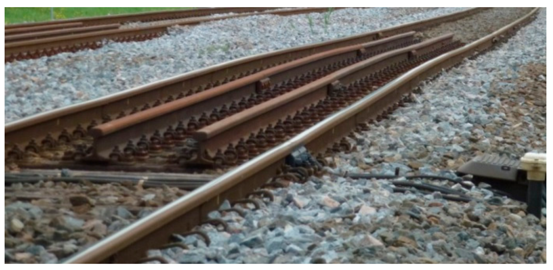
The first category problems can be observed as the degradation of track alignment, which is shown by the measured longitudinal track level in Section 3 and explained in Section 4. Moreover, track irregularities have also been reported in transition zones, e.g., [1,3,4,6,7]. An example of a transition zone with large track irregularities is shown in Figure 16. The second category problems result in maintenance, such as ballast cleaning (undercutting) by ballast cleaners [36,56], or ballast adding by track stoneblower [56,62]. When the problems are not solved timely, frost heave and mud pumping problems may occur. All of the problems cause a significant increase in track maintenance costs and reduction in passenger comfort. A possible solution is to improve the drainage system in transition zones at the design stage, since currently most codes regard the drainage system in transition zones the same as that in free track, e.g., in [63].
Numerical simulations have demonstrated how increased moisture (represented as reduced ballast stiffness) causes dynamic wheel loads to have a greater impact on transition zone structures (ballast/subballast) during loading (train traffic). This may result in a variation of ballast distribution and consequently accelerate ballast settlement. Since most numerical studies of transition zones only consider the difference of the stiffness and settlement in transition zones, e.g., [6,8,11,64], it is suggested to also consider the effect of ballast moisture in future studies.
In addition to the reduction in stiffness, it is also possible to model the ballast with high moisture as a higher growth rate of settlement. In [29], static one-dimensional tests of ballast were conducted to study the effect of the addition of water on ballast deformation. Specimens with added water had a 40% increase in settlement when compared to dry samples. Similar findings from laboratory tests can also be found in [30], where the additional settlement caused by water for fresh and recycled ballast is 39% and 42%. When the ballast is fouled (e.g., by clay and silt), the extra settlement caused by water is even larger [31].

6. Conclusions

To explore the degradation mechanism in transition zones, this paper studies the moisture condition of the ballast and subballast in transition zones experimentally and numerically.
The paper presents results of moisture condition measured in three transition zones using GPR. It has been found that the high moisture areas appear mostly before and after the bridges in transition zones. Track irregularities can also be found at the corresponding locations, which imply a strong connection between the high moisture conditions and track degradation. High moisture areas tend to be located at the bottom of the ballast layer, the bottom of the subballast layer, and above the abutments.
To explain the connection, the dynamic behaviour of the transition zone in a high moisture condition is analysed using the FE method (explicit integration). The ballast and subballast are modelled as solid elements and the high moisture conditions are considered as (50%) reduction of the elastic modulus, according to laboratory findings. It has been found that the average of dynamic wheel load peaks for all wheels in the transition zone in the high moisture condition is slightly increased (ranging from 0.2% to 2.6%) when compared to the reference condition. Since the high dynamic wheel loads will lead to fast track degradation, the simulation results confirm that the high moisture condition is one of the sources of the fast degradation that is often reported in transition zones.
In a real situation, when higher axle loads or velocities of the trains are in use, faster track degradation can be expected in transition zones in a high moisture condition. To prevent it, more attention should be paid to the drainage system of the ballast track in transition zones. In addition, it is recommended to consider the effect of ballast moisture in the future studies of transition zones.

Acknowledgments

This project has received funding from the European Union’s Horizon 2020 research and innovation programme under the Marie Skłodowska-Curie grant agreement No. 691135 “RISEN: Rail Infrastructure Systems Engineering Network”.

Author Contributions

H.W., V.M. and M.S. conceived and designed the experiments; M.S. and B.W. performed the experiments; H.W. and M.S. analyzed the data; H.W. and V.M. developed the analysis model; H.W. wrote the paper; B.W. edited the paper.

Conflicts of Interest

The authors declare no conflict of interest.

References

  1. Li, D.; Davis, D. Transition of Railroad Bridge Approaches. J. Geotech. Geoenviron. Eng. 2005, 131, 1392–1398. [Google Scholar] [CrossRef]
  2. Coelho, B.; Hölscher, P.; Priest, J.; Powrie, W.; Barends, F. An assessment of transition zone performance. Proc. Inst. Mech. Eng. Part F J. Rail Rapid Transit 2011, 225, 129–139. [Google Scholar] [CrossRef]
  3. Stark, T.D.; Wilk, S.T. Root cause of differential movement at bridge transition zones. Proc. Inst. Mech. Eng. Part F J. Rail Rapid Transit 2015, 230, 1257–1269. [Google Scholar] [CrossRef]
  4. Markine, V.; Wang, H.; Shevtsov, I. Experimental Analysis of the Dynamic Behaviour of a Railway Track in Transition Zones. In Proceedings of the Ninth International Conference on Engineering Computational Technology, Naples, Italy, 2–5 September 2014; Iványi, P., Topping, B.H.V., Eds.; Paper 3. Civil-Comp Press: Stirlingshire, UK, 2014. [Google Scholar]
  5. European Rail Research Institute. Embankment Structure Transition: State of the Art Report; European Rail Research Institute: Utrecht, The Netherlands, 1999; Available online: https://books.google.nl/books?id=Sd_mtgAACAAJ (accessed on 10 November 2017).
  6. Nicks, J.E. The Bump at the End of the Railway Bridge. Ph.D. Thesis, Texas A&M University, College Station, TX, USA, 2009. [Google Scholar]
  7. Le Pen, L.; Watson, G.; Powrie, W.; Yeo, G.; Weston, P.; Roberts, C. The behaviour of railway level crossings: Insights through field monitoring. Transp. Geotech. 2014, 1, 201–213. [Google Scholar] [CrossRef]
  8. Wang, H.; Markine, V.L.; Shevtsov, I.Y.; Dollevoet, R. Analysis of the Dynamic Behaviour of a Railway Track in Transition Zones with Differential Settlement. In Proceedings of the 2015 Joint Rail Conference, San Jose, CA, USA, 23–26 March 2015; p. 7. [Google Scholar]
  9. Paixao, A.; Fortunato, E.; Calcada, R. Design and construction of backfills for railway track transition zones. Proc. Inst. Mech. Eng. Part F J. Rail Rapid Transit 2013, 229, 58–70. [Google Scholar] [CrossRef]
  10. Alves Ribeiro, C.; Paixão, A.; Fortunato, E.; Calçada, R. Under sleeper pads in transition zones at railway underpasses: Numerical modelling and experimental validation. Struct. Infrastruct. Eng. 2014, 11, 1432–1449. [Google Scholar] [CrossRef]
  11. Coelho, B.Z. Dynamics of Railway Transition Zones in Soft Soils. Ph.D. Thesis, University of Porto, Porto, Portugal, 2011. [Google Scholar]
  12. Lei, X.; Zhang, B. Influence of track stiffness distribution on vehicle and track interactions in track transition. Proc. Inst. Mech. Eng. Part F J. Rail Rapid Transit 2010, 224, 592–604. [Google Scholar] [CrossRef]
  13. Gallage, C.; Dareeju, B.; Dhanasekar, M. State-of-the-art: Track degradation at bridge transitions. In Proceedings of the 4th International Conference on Structural Engineering and Construction Management, Kandy, Sri Lanka, 13–15 December 2013. [Google Scholar]
  14. Hölscher, P.; Meijers, P. Literature Study of Knowledge and Experience of Transition Zones; Technical Report; GeolDelft: Delft, The Netherlands, 2007. [Google Scholar]
  15. Read, D.; Li, D. Design of Track Transitions; Transit Cooperative Research Program: Research Results Digest 79; Federal Transit Administration: Pueblo, CO, USA, 2006.
  16. Thompson, D.R.; Woodward, P.K. Track stiffness management using the XiTRACK GeoComposite. Perm. Way Inst. J. Rep. Proc. 2004, 122, 135–138. [Google Scholar]
  17. Kerr, A.D.; Moroney, B.E. Track Transition Problems and Remedies; Bulletin 742; American Railway Engineering Association: Landover, MD, USA, 1993; Volume 94, p. 25. [Google Scholar]
  18. Banimahd, M.; Woodward, P.K.; Kennedy, J.; Medero, G.M. Behaviour of train–track interaction in stiffness transitions. Proc. Inst. Civ. Eng.-Transp. 2012, 165, 205–214. [Google Scholar] [CrossRef]
  19. Dahlberg, T. Railway Track Stiffness Variations-Consequences and Countermeasures. Int. J. Civ. Eng. 2010, 8, 1–12. [Google Scholar]
  20. Hunt, H. Settlement of railway track near bridge abutments. Proc. Inst. Civil Eng. Transp. 1997, 123, 68–73. [Google Scholar]
  21. Frohling, R.D.; Scheffel, H.; EbersÖHn, W. The Vertical Dynamic Response of a Rail Vehicle caused by Track Stiffness Variations along the Track. Veh. Syst. Dyn. 1996, 25 (Suppl. 1), 175–187. [Google Scholar] [CrossRef]
  22. Li, D.; Otter, D.; Carr, G. Railway bridge approaches under heavy axle load traffic: Problems, causes, and remedies. Proc. Inst. Mech. Eng. Part F J. Rail Rapid Transit 2010, 224, 383–390. [Google Scholar] [CrossRef]
  23. Varandas, J.N.; Hölscher, P.; Silva, M.A.G. Dynamic behaviour of railway tracks on transitions zones. Comput. Struct. 2011, 89, 1468–1479. [Google Scholar] [CrossRef]
  24. Sasaoka, C.; Davis, D. Long Term Performance of Track Transition Solutions in Revenue Service; Technology Digest TD-05-036; Association of American Railroads: Washington, WA, USA, 2005. [Google Scholar]
  25. Hyslip, J.P.; Li, D.; McDaniel, C. Railway bridge transition case study. In Proceedings of the 8th International Conference on Bearing Capacity of Roads, Railways and Airfields (BCR2A’09), Champaign, IL, USA, 29 June–2 July 2009. [Google Scholar]
  26. Sañudo, R.; Dell’Olio, L.; Casado, J.A.; Carrascal, I.A.; Diego, S. Track transitions in railways: A review. Constr. Build. Mater. 2016, 112, 140–157. [Google Scholar] [CrossRef]
  27. Lekarp, F.; Isacsson, U.; Dawson, A. State of the art. I: Resilient response of unbound aggregates. J. Transp. Eng. 2000, 126, 66–75. [Google Scholar] [CrossRef]
  28. Stark, T.D.; Wilk, S.T.; Thompson, H.B.; Sussmann, T.R.; Baker, M.; Ho, C.L. Evaluating Fouled Ballast Using Seismic Surface Waves. In Proceedings of the 2016 Joint Rail Conference, Columbia, SC, USA, 12–15 April 2016; American Society of Mechanical Engineers: New York, NY, USA, 2016. [Google Scholar]
  29. Indraratna, B.; Ionescu, D.; Christie, D.; Chowdhury, R. Compression and degradation of railway ballast under one-dimensional loading. Aust. Geomech. 1997, 32, 48–61. [Google Scholar]
  30. Indraratna, B.; Khabbaz, H.; Salim, W.; Christie, D. Geotechnical Properties of Ballast and the Role of Geosynthetics; Institution of Civil Engineers, Thomas Telford Ltd.: London, UK, 2006; Available online: http://hdl.handle.net/10453/9243 (accessed on 1 August 2017).
  31. Han, X.; Selig, E.T. Effects of fouling on ballast settlement. In Proceedings of the 6th International Heavy Haul Railway, Capetown, South Africa, 6–10 April 1997. [Google Scholar]
  32. Saarenketo, T. Electrical Properties of Road Materials and Subgrade Soils and the Use of Ground Penetrating Radar in traffic Infrastructure Surveys; University of Oulu: Oulu, Finland, 2006. [Google Scholar]
  33. Daniels, D.J. Ground Penetrating Radar, 2nd ed.; Institution of Electrical Engineers: London, UK, 2005. [Google Scholar]
  34. Wang, H.; Markine, V.L.; Dollevoet, R.P.B.J.; Shevtsov, I.Y. Improvement of train-track interaction in transition zones via reduction of ballast damage. In The Dynamics of Vehicles on Roads and Tracks; CRC Press: Boca Raton, FL, USA, 2016. [Google Scholar]
  35. Wang, H.; Markine, V. Finite element analysis of the dynamic behaviour of track transition zones during train passing processes. Veh. Syst. Dyn. 2017. submitted. [Google Scholar]
  36. Selig, E.T.; Waters, J.M. Track Geotechnology and Substructure Management; Thomas Telford: London, UK, 1994. [Google Scholar]
  37. Haynes, J.H.; Yoder, E.J. Effects of Repeated Loading on Gravel and Crushed Stone Base Course Materials Used in the AASHO Road Test; Purdue University: Lafayette, IN, USA, 1963; Available online: http://docs.lib.purdue.edu/cgi/viewcontent.cgi?article=2767&context=jtrp (accessed on 1 September 2017).
  38. Silvast, M.; Nurmikolu, A.; Wiljanen, B.; Levomaki, M. An inspection of railway ballast quality using ground penetrating radar in Finland. Proc. Inst. Mech. Eng. Part F J. Rail Rapid Transit 2010, 224, 345–351. [Google Scholar] [CrossRef]
  39. Silvast, M.; Nurmikolu, A.; Wiljanen, B.; Levomäki, M. Identifying frost-susceptible areas on Finnish railways using the ground penetrating radar technique. Proc. Inst. Mech. Eng. Part F J. Rail Rapid Transit 2013, 227, 3–9. [Google Scholar] [CrossRef]
  40. Saarenketo, T.; Silvast, M.; Noukka, J. Using GPR on railways to identify frost susceptible areas. In Proceedings of the International Conference and Exhibition Railway Engineering, London, UK, 30 April–1 May 2003. [Google Scholar]
  41. Hugenschmidt, J. Railway track inspection using GPR. J. Appl. Geophys. 2000, 43, 147–155. [Google Scholar] [CrossRef]
  42. Saarenketo, T. Electrical properties of water in clay and silty soils. J. Appl. Geophys. 1998, 40, 73–88. [Google Scholar] [CrossRef]
  43. Clark, M.R.; Gillespie, R.; Kemp, T.; McCann, D.M.; Forde, M.C. Electromagnetic properties of railway ballast. NDT E Int. 2001, 34, 305–311. [Google Scholar] [CrossRef]
  44. Silvast, M.; Levomäki, M.; Nurmikolu, A.; Noukka, J. NDT techniques in railway structure analysis. In Proceedings of the 7th World Congress on Railway Research, Montreal, QC, Canada, 4–8 June 2006. [Google Scholar]
  45. Vorster, D.J.; Gräbe, P.J. The use of ground-penetrating radar to develop a track substructure characterisation model. J. S. Afr. Inst. Civ. Eng. 2013, 55, 69–78. [Google Scholar]
  46. Saarenketo, T. Experiences of integrated GPR and Laser Scanner analysis. In Proceedings of the 17th Nordic Geotechnical Meeting Challenges in Nordic Geotechnic, Reykjavik, Iceland, 25–28 May 2016. [Google Scholar]
  47. Wang, H.; Markine, V.; Shevtsov, I. The Analysis of Degradation Mechanism in Track Transition Zones Using 3D Finite Element Model; Civil-Comp Press: Stirlingshire, UK, 2014; Available online: https://www.researchgate.net/publication/269198691_The_Analysis_of_Degradation_Mechanism_in_Track_Transition_Zones_using_3D_Finite_Element_Model (accessed on 1 July 2017).
  48. Lundqvist, A.; Dahlberg, T. Load impact on railway track due to unsupported sleepers. Proc. Inst. Mech. Eng. Part F J. Rail Rapid Transit 2005, 219, 67–77. [Google Scholar] [CrossRef]
  49. Shi, J.; Burrow, M.P.; Chan, A.H.; Wang, Y.J. Measurements and simulation of the dynamic responses of a bridge-embankment transition zone below a heavy haul railway line. Proc. Inst. Mech. Eng. Part F J. Rail Rapid Transit 2012, 227, 254–268. [Google Scholar] [CrossRef]
  50. Paixao, A.; Fortunato, E.; Calcada, R. A numerical study on the influence of backfill settlements in the train/track interaction at transition zones to railway bridges. Proc. Inst. Mech. Eng. Part F J. Rail Rapid Transit 2015, 230, 866–878. [Google Scholar] [CrossRef]
  51. Alves Ribeiro, C.; Calçada, R.; Delgado, R. Calibration and experimental validation of a dynamic model of the train-track system at a culvert transition zone. Struct. Infrastruct. Eng. 2017, 1–15. [Google Scholar] [CrossRef]
  52. Zhai, W.M.; Wang, K.Y.; Lin, J.H. Modelling and experiment of railway ballast vibrations. J. Sound Vib. 2004, 270, 673–683. [Google Scholar] [CrossRef]
  53. Varandas, J.N.; Holscher, P.; Silva, M.A. Settlement of ballasted track under traffic loading: Application to transition zones. Proc. Inst. Mech. Eng. Part F J. Rail Rapid Transit 2013, 228, 242–259. [Google Scholar] [CrossRef]
  54. Iwnick, S. Manchester Benchmarks for Rail Vehicle Simulation. Veh. Syst. Dyn. 1998, 30, 295–313. [Google Scholar] [CrossRef]
  55. Wan, C.; Markine, V.L.; Shevtsov, I.Y. Improvement of vehicle–turnout interaction by optimising the shape of crossing nose. Veh. Syst. Dyn. 2014, 52, 1517–1540. [Google Scholar] [CrossRef]
  56. Esveld, C. Modern Railway Track; MRT-Productions: Zaltbommel, The Netherlands, 2001; Volume 385, Available online: https://books.google.fi/books/about/Modern_Railway_Track.html?id=DYaQQgAACAAJ&redir_esc=y (accessed on 1 July 2017).
  57. Sato, Y. Japanese Studies on Deterioration of Ballasted Track. Veh. Syst. Dyn. 1995, 24, 197–208. [Google Scholar] [CrossRef]
  58. Dahlberg, T. Some railroad settlement models—A critical review. Proc. Inst. Mech. Eng. Part F J. Rail Rapid Transit 2001, 215, 89–300. [Google Scholar] [CrossRef]
  59. Indraratna, B.; Nimbalkar, S.; Christie, D.; Rujikiatkamjorn, C.; Vinod, J. Field assessment of the performance of a ballasted rail track with and without geosynthetics. J. Geotech. Geoenviron. Eng. 2010, 136, 907–917. [Google Scholar] [CrossRef]
  60. Hallquist, J. LS-DYNA Theoretical Manual; Livemore Software Technology Corporation: Livermore, CA, USA, 1998. [Google Scholar]
  61. Kreiser, D.; Jia, S.X.; Han, J.J.; Dhanasekar, M. A nonlinear damage accumulation model for shakedown failure. Int. J. Fatigue 2007, 29, 1523–1530. [Google Scholar] [CrossRef]
  62. Anderson, W.F.; Key, A.J. Model testing of two-layer railway track ballast. J. Geotech. Geoenviron. Eng. 2000, 126, 317–323. [Google Scholar] [CrossRef]
  63. ProRail. Constructive Measures to Prevent Settlement of the Track (in Dutch Constructieve Maatregelen ter Voorkoming Van Ontoelaatbare Zakkingen Van Het Spoor); ProRail: Utrecht, The Netherlands, 2010. [Google Scholar]
  64. Varandas, J.N. Long-Term Behaviour of Railway Transitions under Dynamic Loading Application to Soft Soil Sites. Ph.D. Thesis, Universidade Nova de Lisboa, Lisbon, Protugal, 2013. [Google Scholar]
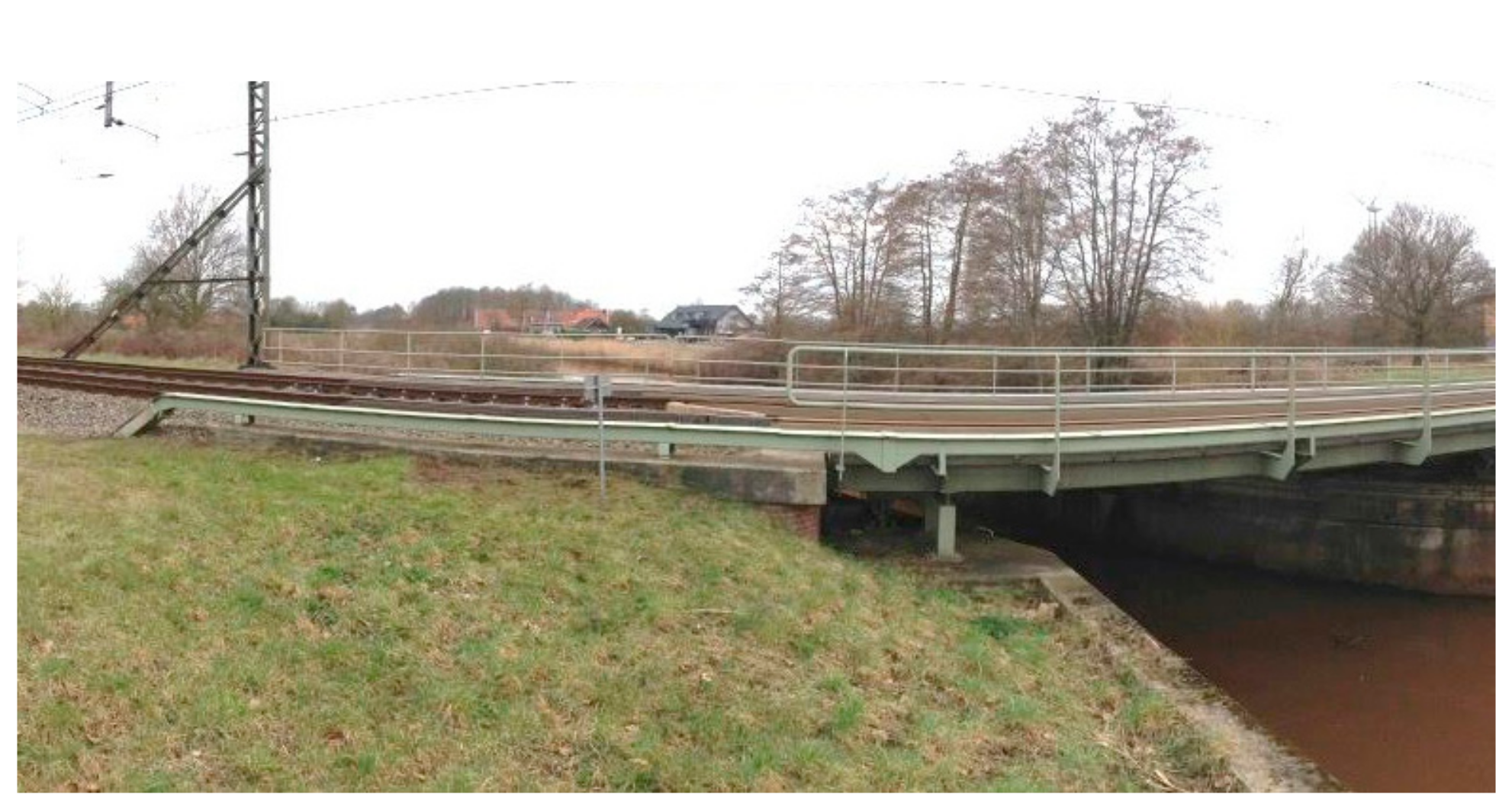
Figure 1. A typical bridge transition zone.
Applsci 07 01208 g001
Figure 2. Measuring principle of ground penetrating radar (GPR). A1 stands for the amplitude of the reflection between the sleeper and ballast; A2 stands for the amplitude of the reflection between the ballast and subballast; t1 stands for the travel time in ballast; t2 stands for the travel time in subballast.
Applsci 07 01208 g002
Figure 3. Railway engine with GPR system: (a) schematic diagram; (b) photograph.
Applsci 07 01208 g003
Figure 4. Measurement results: (a) the digital video; (b) the GPR data.
Applsci 07 01208 g004
Figure 5. Moisture profiles: (a) low moisture; (b) high moisture.
Applsci 07 01208 g005
Figure 6. Measurement results of open track: (a) photograph of the track; (b) the moisture profile; and, (c) the longitudinal track level.
Applsci 07 01208 g006
Figure 7. Measurement results of Transition Zone A: (a) photograph of the track; (b) the moisture profile; and, (c) the longitudinal track level.
Applsci 07 01208 g007
Figure 8. Section of rail in Transition Zone A.
Applsci 07 01208 g008
Figure 9. Measurement results of Transition Zone B: (a) photograph of the track; (b) the moisture profile; and, (c) the longitudinal track level.
Applsci 07 01208 g009
Figure 10. Measurement results of Transition Zone C: (a) photograph of the track; (b) the moisture profile; and, (c) the longitudinal track level.
Applsci 07 01208 g010
Figure 11. Finite Element (FE) model of the track transition zone: (a) full view; (b) cross-section of ballast track.
Applsci 07 01208 g011
Figure 12. Comparisons of measurement and simulation results: (a) the rail close to the bridge in the time domain; (b) the rail far from the bridge in the time domain; (c) the rail far from the bridge in the frequency domain; and, (d) the rail close to the bridge in the frequency domain.
Applsci 07 01208 g012
Figure 13. Simulation of the transition zone with high moisture: (a) the reference case; (b) the high moisture case.
Applsci 07 01208 g013
Figure 14. Dynamic wheel load of Wheel 1: (a) overview; (b) zoom-in of the embankment-bridge side; and, (c) zoom-in of the bridge-embankment side (unit: KN).
Applsci 07 01208 g014
Figure 15. Dynamic wheel loads: (a) zoom-in of the embankment-bridge side of Wheel 2; (b) zoom-in of the bridge-embankment side of Wheel 2; (c) zoom-in of the embankment-bridge side of Wheel 3; (d) zoom-in of the bridge-embankment side of Wheel 3; (e) zoom-in of the embankment-bridge side of Wheel 4; and, (f) zoom-in of the bridge-embankment side of Wheel 4 (unit: KN).
Applsci 07 01208 g015
Figure 16. Transition zone with large track irregularities.
Applsci 07 01208 g016
Table 1. Dielectric constant and the velocity of the signal in various material, data measured by [43].
MaterialDielectric ConstantVelocity (m/s)
Air1.03 × 108
Dry spent ballast4.31.45 × 108
Wet spent ballast (5% water)7.81.07 × 108
Saturated spent ballast38.50.58 × 108
Water81.00.33 × 108
Table 2. Material properties of the track components.
ParameterValue
Sleeper Elastic Modulus (Pa)3.65 × 10¹⁰
Sleeper Poisson’s ratio0.167
Ballast Elastic Modulus (Pa)1.20 × 10⁸
Ballast Poisson’s ratio0.250
Subgrade Elastic Modulus (Pa)1.80 × 10⁸
Subgrade Poisson’s ratio0.250
Concrete bridge Elastic Modulus (Pa)3.50 × 10¹⁰
Concrete bridge Poisson’s ratio0.167
Fastening system horizontal stiffness (N/m)1.5 × 106
Fastening system horizontal damping (N*s/m)5.00 × 104
Fastening system longitudinal stiffness (N/m)1.5 × 106
Fastening system longitudinal damping (N*s/m)5.00 × 104
Fastening system vertical (compression) stiffness (N/m)1.20 × 108
Fastening system vertical (compression) damping (N*s/m)5.00 × 104
Fastening system vertical (tension) stiffness (N/m)1.20 × 1011
Fastening system vertical (tension) damping (N*s/m)5.00 × 104
Distance between wheels (m)2.5
Distance between axles (m)20.0
Length of train body (m)23.0
Primary suspension stiffness (N/m)4.25 × 105
Primary suspension damping (N*s/m)1.00 × 106
Secondary suspension stiffness (N/m)4.68 × 105
Secondary suspension damping (N*s/m)6.50 × 104
Secondary suspension Bending stiffness (Nm/rad)1.05 × 104
Table 3. Increase percentages of the dynamic wheel loads in the high moisture case comparing to the reference case.
PeakWheel 1Wheel 2Wheel 3Wheel 4
−74.72.94.41.1
−63.21.9−0.3−0.7
−52.53.51.6−0.1
−43.22.41.7−3.3
−33.42.94.54.5
−21.6−8.53.0−5.4
−13.51.01.4−1.0
1−2.63.2−4.82.2
23.7−2.55.01.2
3−1.01.9−2.72.4
45.10.84.03.4
5−1.4−1.00.0−2.9
610.00.85.9−1.0
73.13.53.62.1
Average2.60.81.70.2