1. Introduction
Flying an aircraft, especially the fighter plane, is a challenging activity and exposes the pilot to many potential hazards. One of the most significant of these is spatial disorientation (SD), which is a term used to describe a variety of incidents occurring in flight where the pilot fails to sense attitude, or motion of one’s own aircraft relative to the earth or other significant objects [
1]. In aviation accidents and incidents, SD accounts for some six to 32 percent of major accidents, and some 15 to 69 percent of fatal accidents [
1].
There are several factors causing SD problem such as visual and vestibular illusions, fatigue driving, instrument fault, and environmental factors (flight in rain, above sea, through cloud) [
1,
2,
3]. The decline in situation awareness of pilots due to these factors is the direct reason to cause SD problem [
1]. Traditional aircraft instruments, such as gyro-stabilized altitude indicator, HUD, SVS (synthetic visual system), and EVS (enhanced visual system), provide pilots the situation of aircraft via visual or audio channel [
4]. However, the traditional instruments occupy additional audio-visual resources [
5]. Pilots need a high concentration of the auditory and visual channel in accessing information from the vicinity for safe ambulation (e.g., approaching objects and acoustic and visual signals from instruments and alerts), and the two channels will not be available for other cues. Additionally, the pilot cannot keep the situation of aircraft to a suitable standard via the two traditional senses when flying aircraft above the sea [
2], through rain and cloud [
3], or in a condition of altered gravitoinertial acceleration [
6,
7,
8].
According to previous psychological studies, the issues above may be solved by using a free sensory channel liking tactile sense, for example, the multiple resource model of human information processing predicts no performance degradation when independent resources or information channels are used to present information (e.g., refer to [
9,
10]). The advantage of touch is it neither blocks the visual nor the auditory sense [
11]. Employing a tactile channel may release other heavily loaded sensory channels, therefore potentially providing a major safety enhancement [
12]. Due to the convenience and real-timeliness for changing the pattern of tactile stimulation, vibratory stimuli have been widely adopted in haptic displays.
Recently, favourable effects of vibrotactile displays on navigation performance, situational awareness, and workload reduction have been shown in many application, such as vehicle driving, guiding blind people, and particularly in the high workload group [
13,
14,
15,
16,
17]. To date, very few studies have examined the implementation of vibrotactile displays for conveying flight attitude information of aircraft. The flight attitude is an important parameter for pilots to maintain their awareness of situation of aircraft [
3,
18]. During the flight, the pilots should ascertain within about five degrees of pitch and roll information of aircraft. It is required that the vibrotactile display provide multiple tactile patterns to the pilots [
3]. The TSAS (tactile situation awareness system) consisted of 8 × 5 matrices of pneumatic tactors, developed by Rupert and colleagues is perhaps the most fully implemented and tested system. The resolution of encoding flight attitude for this TSAS is high, at about five degrees in fine flight [
3]. In their coding methods, vibrotactile patterns with different vibration intensity were employed to cue precise angle information. However, coding methods with intensity did not produce intuitive vibrotactile patterns mapping corresponding angles, and need long periods of training to master the vibrotactile commands conveyed by the TSAS in practice.
The coding strategies for these vibrotactile displays have so far been rather basic [
19]. An intuitive and well-perceivable coding method can reduce training time and increase user acceptance of a tactile device. According to previous work in enhancing pilots’ spatial awareness with vibrotactile devices, the parameters that can be used to encode flight information include three basic dimensions: spatial location, temporal rhythm and intensity of vibration [
20]. However, systematic investigations into coding strategies for conveying flight attitude information with a combination of multiple coding parameters are exceptional rare in reported work. A combination of multiple coding parameters are essential to improve the effectiveness of vibrotactile display, since we can determine the vibrotactile coding capacity of each vibration parameters and differences between the perceptions of vibrations with different parameters. The test results of the vibrotactile display designed by [
21,
22] illustrated that the best way to encode information with tactile channel is using the coding parameter with as many dimensions as possible. For instance, spatiotemporal patterns will yield superior identification over spatial patterns and patterns encoded by a single motor’s intensity for an area of skin [
23].
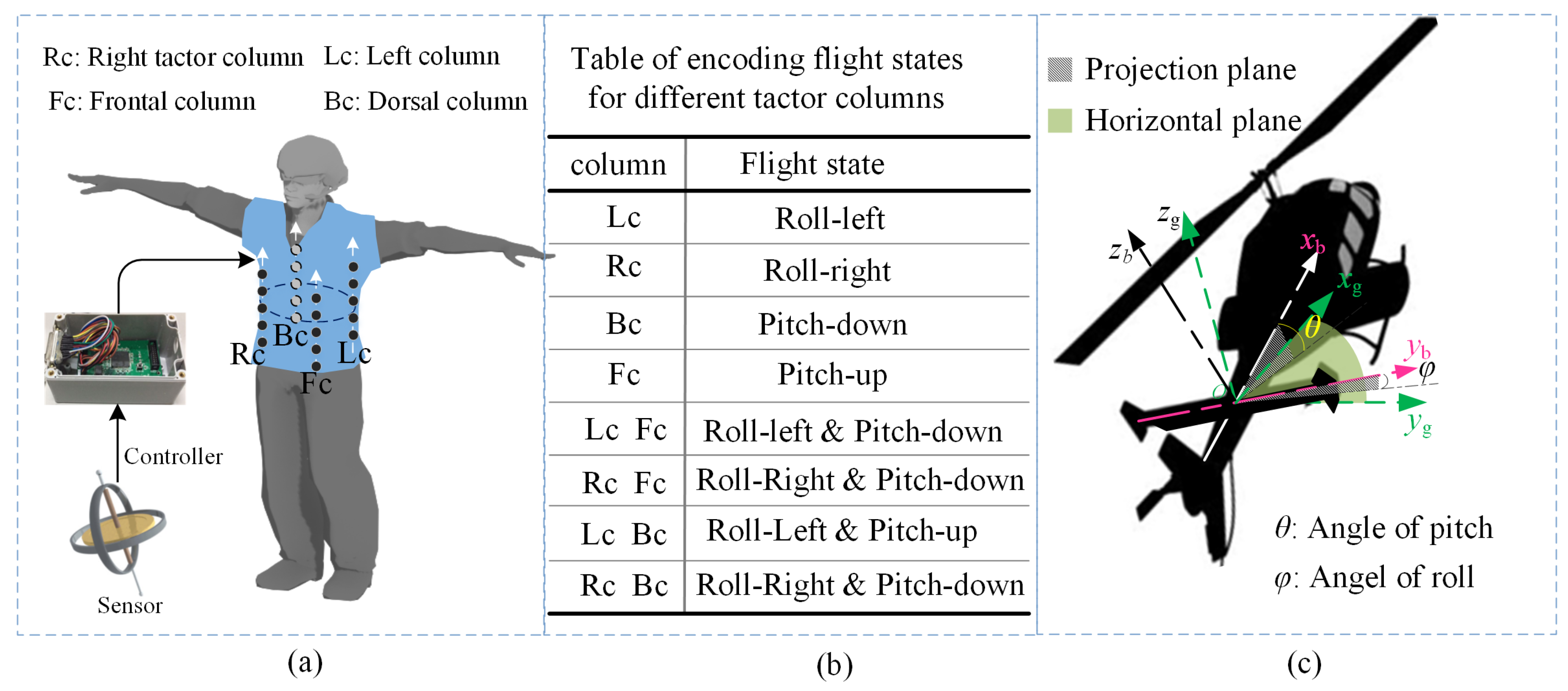
The goal of this work is to investigate preferred coding methods with a combination of multiple coding parameters for cueing precise directional information through vibrotactile feedback, using well perceivable and easily comprehensible vibrotactile patterns. The torso provides an extensive haptic space for presenting tactile information, with approximately half the total surface area of the body. The skin covering the torso is capable of precisely encoding information since it contains hundreds of mechanoreceptors [
24,
25]. In addition, a belt-type device can be worn under a coat without attract public attention. Therefore, we focus on vest-type device to convey vibrotactile feedback for flight attitude of aircraft, and systematically investigated the coding methods with combination of parameters: location, rhythm, intensity, and modal.
3. Psychophysical Experiments
The tactile experiments are static stimulating tests, where the subjects wearing the vibrotactile vest perceived vibrations encoding attitude information in a stationary condition (see
Figure 5). The objective of the experiments is to investigate the preferred coding method with combination of multiple vibration parameters.
3.1. Participants
The participants in this study were 20 postgraduate students of aerospace (18 males and two female), randomly recruited from the Nanjing University of Aeronautics and Astronautics. Their average age was 24 years (SD = 3 years). Their average flight experience in flight simulation was 860 h (SD = 125 h). All participants gave informed consent and received compensation for their time (RMB 100 per participant).
3.2. Experimental Design
Independent variables: we employed a within-subjects repeated measures design, with coding methods (CMs) as a between-subject factor and flight states as a within-subject factor ( roll-left, roll-right, pitch-up and pitch-down state).
Dependent variables: recognition accuracy and reaction time were implemented to evaluate the effectiveness of vibrotactile belt for cueing angle information.
Recognition accuracy is defined as the percentage of correct recognition of vibrotactile commands. Under the condition of correct judgment for flight states, we classified an identification with a difference between a reported and set angle no more than five degrees as a correct recognition, otherwise it was a wrong recognition. Recognition accuracy is proportion of number of correct recognitions to total number of commands.
Reaction time defined as the elapsed time between finishing the display of the vibrotactile command and the moment when the subject has reported a given angle. It should be noted that the time spent on clicking some buttons for reporting the corresponding angles was not included in the reaction time (the time taken for clicking buttons can be recorded in experimental software).
Information transfer rate (bits/min): to statistically analyze the preference of coding methods, we further calculate the information transfer rate (ITR) as shown in Equation (
1). The most popular method for ITR calculation in brain-computer interface (BCI) research was defined by Wolpaw et al. in 1998, which is a simplified computational model based on Shannon channel theory under several assumptions [
36,
37].
Generally, in bits/min is used to indicate the ITR, N is the number of possible choices and P is the probability that the desired choice will be selected, also called target identification accuracy or classifier accuracy. T (seconds/symbol) is the time needed to convey each symbol. In the current study, N can be seen as the total number of angles (60), T can be seen as the reaction time for each vibrotactile pattern, and P is obviously the recognition accuracy. The ITR is more comprehensive than recognition accuracy or reaction time for taking account of both the two evaluating criterion.
3.3. General Procedures
At the beginning of experiments, subjects were prompted to sit comfortably on a chair. They were asked to wear headphones playing white noise (see
Figure 5). The headphone was important to block out sounds from the vibrotactile display as well as the office environment. Before the experiment started, the objective and the function of the vest was explained. A total of 52 vibrotactile patterns encoding attitude angles except for the angles ranging from 0 to 5 degrees the angle of more than 90 degrees, which were presented in sequential order to familiarize the subjects with the meanings of the patterns. For each coding method, the subjects should receive training for 10 min before starting formal experiments.
In the formal experiment, 52 × 3 trials were presented for each coding method via an experimental software. Thus for each subject, a total number of 1092 (52 × 3 × 7) trials were recorded throughout the whole experiment. At the end of each trial, subjects needed to report the flight attitude angles by clicking corresponding radio button in the experimental software. To avoid fatigue, participants could take a break between trials and sessions on request. In order to avoid biased responses, angles were presented in a pseudo-randomized order. The subjects needed to select the direction within the prescribed time (6 s). To reduce the practice and habituation error easily occurring in a psychological experiment [
38], a random vibration pattern different from before was given to the subject when a judgement timed-out occurred. During the formal experiment, no feedback about correctness of the answers was given. The subject’s selected angle and reaction time were recorded in a database. After the completion of each coding method, subjects were asked to complete a questionnaire and provide a ranking of their preferred vibrotactile coding method.
To assess the impact of the coding method on the performance, we analyzed the data by employing a one-way within-subjects design ANOVA, using standard software (IBM SPSS statistics 20, IBM Corp., New York, NY, USA). The within-subjects factor is the coding methods. Simple main effects comparisons and post hoc analysis with Bonferroni correction were further performed to test the significant interaction effects. Wilcoxon signed rank tests and Friedman tests were conducted to compare the preferences among coding methods. We employed a one-way repeated measure multivariate analysis of variance (MANOVA) to test our objective measures.
3.4. Experiment 1
The Experiment 1 was conducted to find the preferred coding methods with a combination of two parameters.
3.4.1. Vibrotactile Coding Design
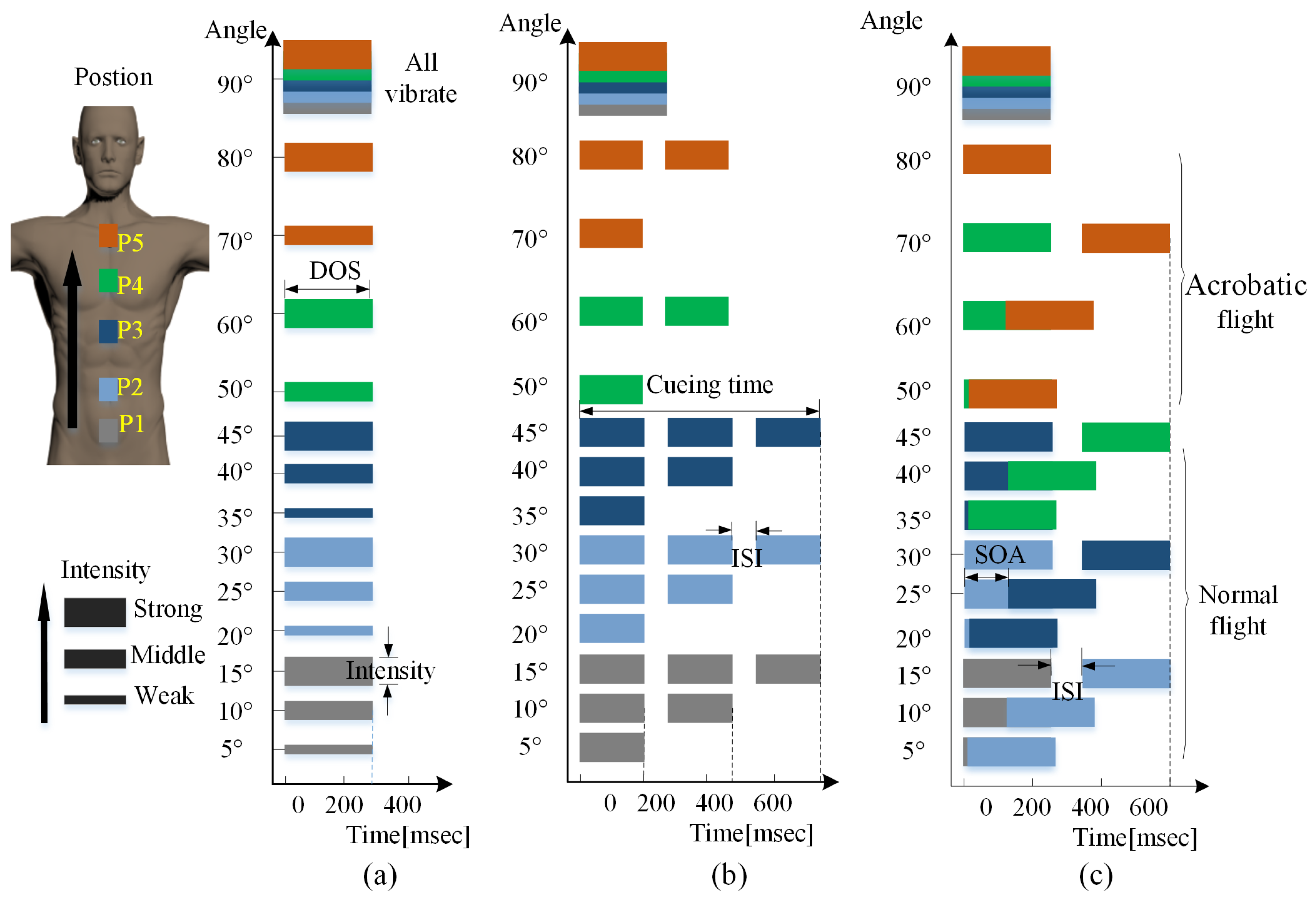
Since the parameter of vibrating location is mandatory in cueing information, there were three different combinations with two parameters as illustrated in
Figure 6.
LI coding method. The angles within group shown in Table 1 was cued by vibration patterns with different intensity as illustrated in
Figure 6a. The most obvious merit of this coding method is that the cueing time is short (300 ms).
LR coding method. The main idea of the second rendering method is to activate different times of corresponding tactor, depending on the angles within the group, as depicted in
Figure 6b. The ISI and DOS was set to 60 ms and 150 ms, respectively, for each tactor at all angle levels.
LM coding method. In the third coding method, the angles within the group were encoded by activate adjacent pair of tactors in different vibrating mode (simultaneous, continuous and discrete) as illustrated
Figure 6c. As is similar with the coding method LR, the same intensity was applied to all angle levels.
Overall, the intensity, rhythm and mode is combined with lactation in LI, LR, and LM coding method, respectively, to cue all the angles in each flight state.
3.4.2. Experimental Results
The results of Experiment 1 are depicted in
Figure 7.
To quantitatively analyse the preference of combinations in term of recognition accuracy, post hoc tests with Bonferroni were performed.
As seen in
Table 3, both LM and LR perform better than LI with significant difference (Z = −0.3580,
p = 0.000), (Z = −0.2420,
p = 0.005), respectively). LR perform better than LM but without a significant difference (Z = 0.1160,
p = 0.122). As seen from the
Figure 6, the cueing time of LR is shorter than that of LM. Overall, it can be obtained that the LR is the preferred combination of two vibration parameters.
3.5. Experiment 2
In the Experiment 1, we have determined that the LR (location and rhythm) is the preferred coding method of cueing attitude. In order to study whether there is improvement on performance when adding another vibration parameter at the basis of LR coding method, another experiment was carried to determine the preferred combinations of three vibration parameters.
3.5.1. Vibrotactile Coding Design
To enhance the discrimination between angle groups in
Table 1, the vibration intensity or mode was employed as an additional coding parameter to facilitate the memorizing and mastering of the coding methods, and improve recognition accuracy.
LRI1 coding method combines with the parameters of location, rhythm and intensity. Compared to the LR coding method, the LRI1 coding method takes vibrating intensity as the additional coding parameter to enhance the discrimination between groups. As similar with LRI1, the LRI2 also uses vibrating intensity as the additional coding parameter, but implemented the rhythm with a different duration of stimulus as the main coding parameter. As similar with LRI1, the LRI3 also make use of vibration times to indicate different angles within the group, but the cueing time for all the angles are same. In order to facilitate the memorizing of vibrotactile patterns mapping angles, vibrating mode was employed as an additional coding parameter to distinguish between normal and acrobatic flight in the LRM method.
Figure 8 shows the schematic diagram of coding methods with combination of three parameters.
3.5.2. Experimental Results
The average recognition accuracy and reaction time from all total trials was about 95 percent (SD:11 percent) and 1.02s (SD: 0.52 s) as illustrated in
Figure 9. It can be seen that in all conditions, the coding method with combination of three parameters performed better than that of two parameters. To quantitatively analyze the preference of combinations in terms of recognition accuracy, post hoc tests with Bonferroni were performed.
In order to intuitively compare the performances of all the coding methods considering both recognition accuracy and reaction time, we further carry a ITR analysis as illustrated in
Figure 10.
As seen in
Figure 10, there is a significant effect of CM on ITR, and LRM has the highest ITR among the proposed coding methods, which is in accordance with results of ANOVA analysis (
Table 4).
In order to further improve the recognition accuracy of the vibrotactile display. We carry a three-way repeated measure MANOVA to study whether there is significant difference of performance between levels of each coding parameter in the preferred coding method (LRM). There are four independent variables: flight states (four levels), locations (five levels), rhythms (two levels), and one dependent variable: recognition accuracy.
As seen in
Table 4, there are no significant difference of performance between levels of each coding parameter, except for the parameter of location (
= 2.97,
p = 0.032). In order to further improve the design of vibrotactile device and its coding strategy. We analysis the correct percentage changing with the set angle as shown in
Figure 11.
As seen in
Figure 11, the average recognition accuracy of all the angles exceeded 90%. The recognition accuracy at the angles ranging from 20 to 40 degrees and 60 degrees appear to be greater in terms of volatility than other angles. These angles were cued by tactor P2, P3, and P4, respectively (see
Figure 2). The questionnaire also indicates that most of the subjects reported that they have difficulty in discriminating vibrations from these tactors, which is in accordance with the result of
Table 5. It suggests that the setting sites for these tactors should be adjusted to further improve the perceptual performance of the vest.
4. Discussion
In this study, we have designed a vibrotactile vest to cue attitude information of aircraft for pilots and systematically investigated the effectiveness of vibrotactile coding methods with a combination of multiple vibration parameters.
The experimental data shows that, in general, the participants were positive about the use of vibrotactile vest to provide flight attitude. The experimental results also indicate that the rhythm performed better than coding parameters of intensity and mode (see
Table 3). The average reaction time for the preferred coding method (LRM) is about 0.9 s, which meets the requirements of reducing pilots’ spatial disorientation with tactile command. In the current study, subjects received training for only 10 min, thus the presented vibrotactile vest can be further improved on the reaction time to which the pilots respond to the vibrotactile patterns.
It should be noted that there may be more discrimination between the different vibrotactile patterns if participants were driving a real aircraft instead of being seated, due to the continuous change of direction in practice. Besides the design of the current vibrotactile vest, it is convenient to wear for people of different waist sizes.
4.1. Comparisons with Previous Work
As a review of previous TSASs successfully implemented in aviation, there are several types of vibrotactile displays to cue situation information for pilots [
3,
18,
39]. The comparison between their and our work on tactor cued is illustrated in
Table 6.
The TSAS developed by the US Navy consists of 40 tactors, and was successfully implemented to cue flight attitude with a resolution of five degrees [
3]. In this TSAS, different attitude angle ranges were cued by different tactors, and fine angle intervals in each range were indicated by corresponding intensity levels (i.e., LI coding method). The belt-type TSAS consisted of eight tactors, designed by Cardin et al. and can only be used to indicate the four basic flight states as shown in
Figure 3b. In this TSAS, different flight states were indicated by different vibration locations [
18]. As similar with the belt-type TSAS, the TSAS in literature [
39] utilized the 60 torso tactors, with each ring mapped to at least 30 degree of the vertical dimension and each column mapped to 30 degree of the horizontal dimension. The TSAS in current work present attitude information of a similar resolution with the TSAS in literature [
3] but using less tactors. Although some TSASs in reported work were also used to cue other situational information such as flight height and drifting direction, which we did not include in the current work, this information can be presented by improving the coding strategies in our current vibrotactile design. It will be discussed in following section.
4.2. Limitations of our Work
Although the TSAS in our current work is successfully implemented to cue attitude situation information and yield a resolution of five degrees, but not indicate other situational information such as flight height, drifting direction and velocity, which is also important to enhance the situation awareness and the reduce sensory workload during flight [
20,
40]. Fortunately, it is feasible to display integrated situation information by improving the coding strategies without changing the hardware design of the current vibrotactile system. For instance, the current vest consists of five rings of four-tactor arrays, the tactor rings from down to up can just be used to display five levels of flight height: low altitude flight, hollow flight, high-altitude flight, and ultrahigh altitude flight, respectively. Besides, the funnel tactile illusion can be implemented in each ring to cue a precise drifting direction and the horizontal velocity.


